Carrier 50Xt Users Manual P1 6
50XT to the manual 23c785cd-d9f9-4aef-be01-f51f5d18f476
2015-01-24
: Carrier Carrier-50Xt-Users-Manual-310832 carrier-50xt-users-manual-310832 carrier pdf
Open the PDF directly: View PDF ![]() .
.
Page Count: 38
1
50XT
Infinity 15tSEER Single---Packaged Heat Pump System
with Puronr(R---410A) Refrigerant
Single Phase
2---5 Nominal Tons (Sizes 024---060)
Product Data
A05307
Fig. 1 -- Unit 50XT
Single--Packaged Products with energy--saving features and
Puron®refrigerant.
SUp to 15.5 SEER
SUp to 8.0 HSPF
SUp to 12 EER at 95°F(35°C) OD
SLow Sound Levels
SVariable--Speed Blower (Standard)
SFactory--Installed TXV
STwo--stage cooling and heat pump operation
FEATURES/BENEFITS
One--piece Heat Pump unit with optional electric heater, low
installation cost, dependable performance and easy maintenance.
Efficient operation
High--efficiency design with SEERs (Seasonal Energy Efficiency
Ratio) of up to 15.5.
Puron®environmentally--sound refrigerant is Carrier’s unique
refrigerant designed to help protect the environment. Puron is an
HFC refrigerant which does not contain chlorine that can harm the
ozone layer. Puron refrigerant is in service in millions of systems
proving highly reliable, environmentally sound performance.
Comfort Heat Pump System with IdealHumiditytfeaturing
Infinitytcontrol variable--speed blower motor and two--stage
cooling and heating that provides greater comfort, humidity
control, and energy efficiency.
Variable--speed blower motors provide better comfort and energy
efficiency. You can expect up to 30 times better dehumidification;
economical constant airflow which provides improved indoor air
quality and more even temperatures from room to room; and
reduced indoor noise due to lower air velocity. In addition, you’ll
realize improved installation flexibility with 3 different airflow
choices for best overall comfort.
Easy installation
Factory--assembled package is a compact, fully self--contained heat
pump unit that is pre--wired, pre--piped, and pre--charged for
minimum installation expense. 50XT units are available in a
variety of standard capacity ranges. Units install easily on a rooftop
or at ground level.
Durable, dependable components
Compressors have two stages of cooling and heating and are
designed for high efficiency. Each compressor is hermetically
sealed against contamination to help promote longer life and
dependable operation. Vibration isolation provides quiet operation.
Compressors have internal high--pressure and overcurrent
protection.
Convertible duct configuration
Unit is designed for easy use in either downflow or horizontal
applications. Each unit is easily converted from horizontal to
downflow with two duct covers (available as an accessory).
Downflow operation is easily provided in the field to allow vertical
ductwork connections. The basepan utilizes knockout style seals
on the bottom openings to ensure a positive seal in the horizontal
airflow mode.
Direct--drive, variable--speed blower motor is standard on all
50XT models.
Direct--drive, PSC condenser fan motors are designed to help
reduce energy consumption and provide for cooling operation
downto55°F (12.7°C) outdoor temperature. Low--ambient
cooling is available below 55°F (12.7°C) when low--ambient
cooling is enabled in the User Interace (UI). Motormaster®II
low--ambient kit is not required.
InfinitytUser Interface is designed to work as a system with
Carrier’s single--packaged product.
Refrigerant system is designed to provide dependability. Liquid
refrigerant filter driers are used to promote clean, unrestricted
operation. Each unit leaves the factory with a full Puron refrigerant
charge. Refrigerant service connections make checking operating
pressures easier.
Indoor and outdoor coils are computer designed for optimum
heat transfer and cooling efficiency. The indoor coil is fabricated
from copper tube and aluminum fins and is located inside the unit

2
for protection against damage. The outdoor coil is internally
mounted on the top tier of the unit. Copper fin coils and pre--coated
fin coils are available from the factory by special order. These coils
are recommended in applications where aluminum fins are likely to
be damaged due to corrosion. They are ideal for seacoast
applications.
Thermostatic expansion valve (TXV) —A hard--shutoff, balance
port TXV maintains a constant superheat at the evaporator exit
(cooling cycle) resulting in higher overall system efficiency.
High-- and low--pressure switches give added safety and
reliability to the compressor.
Low sound ratings ensure a quiet indoor and outdoor
environment with sound ratings as low as 75 dBA.
Easy to service cabinets provide easy single--panel accessibility to
serviceable components during maintenance and installation. The
basepan, with integrated drain pan, provides easy ground level
installation with or without a mounting pad. Convenient handholds
are provided to manipulate the unit on the job site. A nesting
feature ensures a positive basepan to roof curb seal when the unit is
roof mounted. A convenient 3/4--in. wide perimeter flange makes
frame mounting on a rooftop easy.
Louvered grille provides hail and vandalism protection for the
coil.
Cabinets are constructed of heavy--duty, phosphated, zinc--coated,
pre--painted steel capable of withstanding 500 hrs of salt spray.
Interior surfaces of the evaporator and electric heater compartments
are insulated with cleanable, semi--rigid insulation board, which
keeps the conditioned air from being affected by the outdoor
ambient temperature and provides improved indoor air quality.
(Conforms to American Society of Heating, Refrigeration and Air
Conditioning Engineers No. 62P.) The sloped drain pan minimizes
standing water in the unit, which is provided with an external
drain.
Short--cycling protection for the compressor is incorporated into
our Infinity heat pump/air conditioner dual capacity control board
ensuring a five--minute delay before restarting compressor after
shutdown for any reason.
Limited Warranty—Standard 5--year limited warranty on all parts
and10--yearlimitedwarrantyoncompressor.
TABLE OF CONTENTS
FEATURES/BENEFITS 1--2.......................................................................................
MODEL NUMBER NOMENCLATURE 3...........................................................................
ARI CAPACITIES 3.............................................................................................
PHYSICAL DATA 4.............................................................................................
OPTIONS AND ACCESSORIES 5--6...............................................................................
BASE UNIT DIMENSIONS 7--8...................................................................................
ACCESSORY DIMENSIONS 9....................................................................................
SELECTION PROCEDURE 10....................................................................................
PERFORMANCE DATA 11--30....................................................................................
TYPICAL PIPING AND WIRING 31...............................................................................
APPLICATION DATA 32.........................................................................................
ELECTRICAL DATA 33.........................................................................................
TYPICAL WIRING SCHEMATICS 34..............................................................................
CONTROLS 35.................................................................................................
GUIDE SPECIFICATIONS 36--37..................................................................................
50XT
3
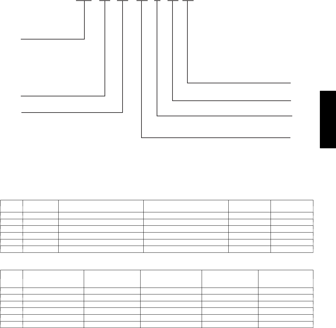
MODEL NUMBER NOMENCLATURE
50XT 0 1024 3
Type of Unit
50XT - Packaged
Electric Heat Pump
Nominal Cooling Capacity
024 - 2 Ton
030 - 2.5 Ton
036 - 3 Ton
042 - 3.5 Ton
048 - 4 Ton
060 - 5 Ton
N/A
– – –
Options
BT - AL evap, vinyl condens
CC - AL evap, CU condens
CU - CU evap & condens
TP - Base unit with tin plated
indoor coil hairpins
TV - TP with vinyl coating on outdoor coil
TC - TP with AL indoor coil and
CU/CU outdoor coil
Only used if ordering an option
– –
Series
Electrical Supply
3- 208/230-1-60
Packaging
LEGEND
AL - Aluminum
CU - Copper
ARI* CAPACITIES
Cooling Capacities and Efficiencies
UNIT
50XT
NOMINAL
TONS
STANDARD CFM (High/Low Stage)
(Cooling & Heating)
NET COOLING CAPACITIES (Btuh)
(High/Low Stage) EER @A{SEER‡
024 2800 / 600 22,600 / 17,600 11.4 15.5
030 2--1/2 1000 / 700 28,600 / 21,400 11.6 15.0
036 31200 / 850 34,600 / 24,400 12 15.0
042 3--1/2 1500 / 975 40,500 / 29,000 11.6 15.0
048 41600 / 1100 46,000 / 33,400 11 15.0
060 51750 / 1200 57,000 / 40,500 11 14.5
Heating Capacities and Efficiencies
UNIT
50XT
HIGH HEAT CAPACITY
(BTUH) @ 47°F(8.3°C)
(High/Low Stage)
HIGH HEAT COP
@47°F(8.3°C)
(High/Low Stage)
LOW HEAT CAPACITY
(BTUH) @ 17°F(--8.3°C)
(High/Low Stage)
LOW HEAT COP
@17°F(--8.3°C)
(High/Low Stage)
HSPF‡
024 20,800 / 16,800 3.3 / 3.2 11,600 / 8,400 2.2 / 1.8 8.0
030 27,600 / 20,400 3.5 / 3.5 14,000 / 9,600 2.1 / 1.9 8.0
036 33,600 / 23,000 3.4 / 3.4 17,200 / 11,200 2.4 / 1.7 8.0
042 39,500 / 27,600 3.6 / 3.5 20,600 / 14,200 2.3 / 2.0 8.0
048 45,500 / 32,200 3.3 / 3.5 25,000 / 15,200 2.4 / 1.9 8.0
060 56,000 / 39,500 3.2 / 3.3 30,800 / 20,400 2.2 / 1.9 8.0
{”A” conditions---80°F (26.6°C) indoor db/67°F (19.4°C) indoor wb & 95°F(35°C) outdoor db.
}Rated in accordance with U.S. Government DOE (Department of Energy) test procedures and/or ARI Standards 210/240.
** Tested in accordance with ARI Standard 270---95 (not listed in ARI).
NOTES:
1. Ratings are net values, reflecting the effects of circulating fan heat. Ratings are based on:
Cooling Standard: 80°F (26.6°C) db, 67°F (19.4°C) wb indoor entering ---air temperature and 95°F(35°C) db outdoor entering---air temperature.
2. Before purchasing this appliance, read important energy cost and efficiency information available from your retailer.
LEGEND
dBA—Sound Levels (decibels)
db—Dry Bulb
SEER—Seasonal Energy Efficiency Ratio
wb—Wet Bulb
COP—Coefficient of Performance
HSPF—Heating Season Performance Factor
50XT
4
PHYSICAL DATA
UNIT SIZE 024 030 036 042 048 060
NOMINAL CAPACITY (ton) 22 --- 1 / 2 33 --- 1 / 2 4 5
OPERATING WEIGHT (lb)
(kg)
405
184
435
197
464
210
476
216
492
223
535
243
COMPRESSOR Tw o --- S t a g e S cr o l l
REFRIGERANT: PURON (R---410A) Quantity (lb)
(kg)
10.3
4.7
11.5
5.2
9.7
4.4
14.0
6.4
15.5
7.0
16.0
7.3
EXPANSION DEVICE ---HEATING AccuRater
ORIFICE OD (in.) --- Left 0.042 0.038 0.035 0.040 0.038 0.046
ORIFICE OD (in.) --- Right 0.038 0.035 0.042 0.046 0.046
EXPANSION DEVICE ---COOLING TXV
Size 2Ton 3Ton 3Ton 4Ton 4Ton 5Ton
Part Number EA36YD129 EA36YD139 EA36YD139 EA36YD149 EA36YD149 EA36YD159
OUTDOOR COIL
Rows…Fins/in. 2…21 2…21 2…21 2…21 2…21 2…21
Face Area (sq. ft.) 13.6 15.3 17.5 19.4 19.4 23.3
OUTDOOR FAN
Nominal Cfm 2700 2700 2800 2800 3300 3300
Diameter (in.)
(mm)
22
559
22
559
22
559
22
559
22
559
22
559
Motor HP (RPM) 1/8 (825) 1/8 (825) 1/8 (825) 1/8 (825) 1/4 (1100) 1/3 (1110)
INDOOR COIL
Rows…Fins/in. 3…17 3…17 3…17 3…17 3…17 4…17
Face Area (sq. ft.) 3.7 3.7 4.7 4.7 5.7 5.7
INDOOR FAN
Nominal Airflow (Cfm)
Comfort Variable based on Comfort Settings (see User Interface instructions for more information).
Efficiency 700 875 1050 1225 1400 1750
Max 800 1000 1200 1400 1600 2000
Size (in.)
(mm)
10x10
254x254
10x10
254x254
11x10
279x254
11x10
279x254
11x10
279x254
11x10
279x254
Motor HP (RPM) 1/2 1/2 3/4 3/4 3/4 1
HIGH---PRESSURE SWITCH (psig)
Cutout 670 ±10
Reset (Auto) 470 ±25
HIGH---PRESSURE SWITCH 2 (psig)
(Compressor Solenoid)
Cutout 565 ±15
Reset (Auto) 455 ±15
L O S S --- O F --- C H A R G E / L O W --- P R E S S U R E S W I T C H
(Liquid Line) (psig)
Cutout 23 ±5
Reset (Auto) 55 ±5
RETURN ---AIR FILTERS Throwaway (in.)*
(mm)
20x24x1
508x610x25
24x30x1
610x762x25
24x36x1
610x914x25
*Recommended filter sizes for field---installed air filter grilles mounted on the wall or ceiling of the conditioned structure. Required filter sizes shown are based
on the larger of the ARI (Air Conditioning and Refrigeration Institute) rated cooling airflow or the heating airflow velocity of 300 ft/minute for throwaway type or
450 ft/minute for high---capacity type. Air filter pressure drop for non ---standard filters must not exceed 0.08 IN. WC.
REGISTERED
ISO 9001:2000
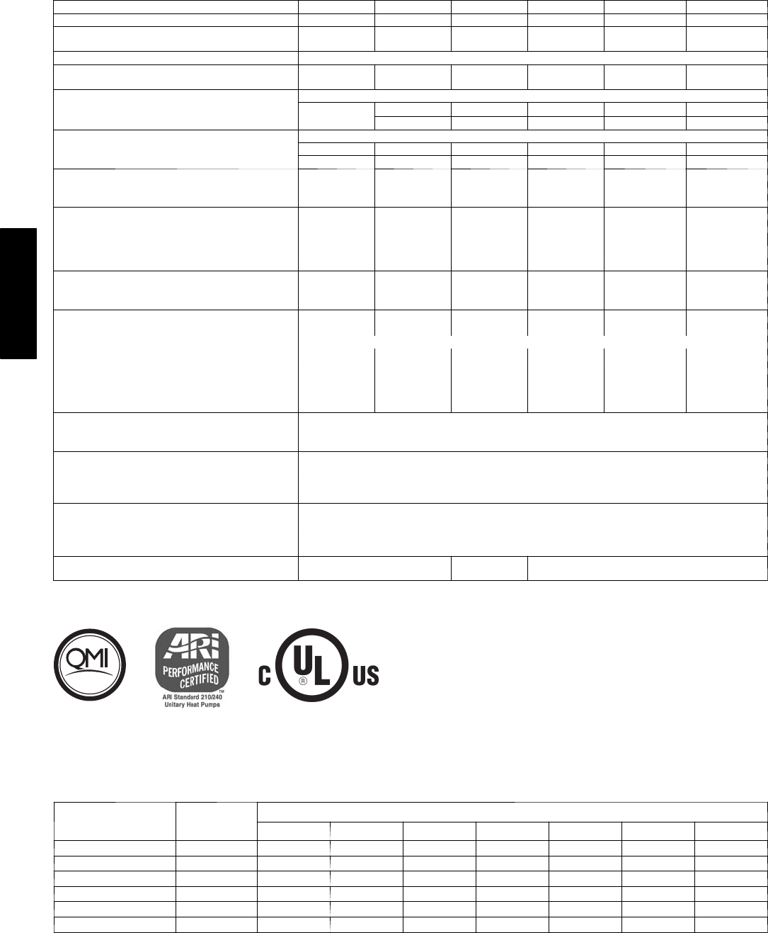
A--WEIGHTED SOUND POWER LEVEL (dBA)
MODEL 50XT
STANDARD
RATING
(dBA)
TYPICAL OCTAVE BAND SPECTRUM (dBA) (without tone adjustment)
125 250 500 1000 2000 4000 8000
024 75 58.8 63.5 67.2 66.9 63.7 58.3 50.0
030 75 58.8 63.5 67.2 66.9 63.7 58.3 50.0
036 75 60.7 63.3 66.8 66.5 64.2 60.3 53.0
042 75 56.7 62.8 67.8 67.4 63.7 57.7 50.8
048 78 62.4 69.9 71.3 73.4 70.0 66.3 60.1
060 78 63.5 67.6 71.8 75.5 71.0 68.1 59.9
NOTE: Tested in accordance with ARI Standard 270 ---95 (not listed in ARI).
50XT
5
OPTIONS AND ACCESSORIES
Factory--installed options
Coil options include tin--plated* indoor hairpins, copper/copper
and vinyl--coated construction for refrigerant coils. Units are
shipped standard with copper tube/aluminum fin construction. See
model number nomenclature for coil options.
*Tin--plated indoor coils are built with special hairpins that are
designed to resist both general pitting corrosion and excessive
indoor corrosion (Formicary Corrosion).
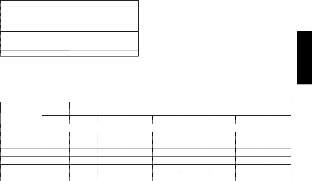
Field--installed accessories
Manual Air Damper (25% open)
Electric Heaters
Filter Rack
Flat Roof Curbs (8--in. and 14--in.) (203 mm and 256 mm)
Square--to--Round Duct Transition Kit
InfinitytUser Interface
Crankcase Heater
Lifting Kit
Compressor Hard Start Kit
Manual outside air damper includes hood and filter rack with
adjustable damper blade for up to 25% outdoor air.
Electric heaters provide additional heat in the unit when required.
Each package has a heater module that slides into the controls
compartment. Heater sizes range from 5.0 to 20.0 kW. The electric
heater design allows the use of a single--point power supply for the
entire unit, resulting in lower installed costs.
Flat roof curbs in both 8 in. (203 mm) and 14 in. (256 mm) sizes
are available for roof mounted applications.
Square--to--round duct transition kit enables 024--048 size units
to be fitted to 14 in. round ductwork.
Infinity User Interface coupled with the system’s variable--speed
indoor blower delivers Carrier’s patented IdealHumidity
technology that allows for even greater humidity control. Along
with more precisely controlling temperature and humidity, the
Infinity User Interface offers full seven--day programmability
allowing you to further customize your comfort and energy
savings.
Lifting kit includes 4 metal brackets that are available to assist in
lifting this product onto a roof application.
Crankcase heater provides anti--floodback protection for
low--load cooling applications.
Filter rack features easy installation, serviceability, and
high--filtering performance for vertical or horizontal applications.
Compressor hard start kit assists compressor start--up by
providing additional starting torque on single phase units and
prolongs compressor motor life.
Electric Heaters
CATALOG
ORDERING NO.
NOMINAL
CAPACITY USED WITH SIZES
(kW) FUSED STAGES 24 30 36 42 48 60
208/240 — SINGLE PHASE (60 Hz)
CPHEATER080A00 3.8 / 5.0 NO 1 X X X
CPHEATER081A00 3.8 / 5.0 YES 1 X X X
CPHEATER083A00 5.4 / 7.2 YES 1XXXXXX
CPHEATER085A00 7.5 / 10.0 YES 1 XXXXXX
CPHEATER087A00 11.3 / 15.0 YES 2 X X X X X
CPHEATER089A00 15.0 / 20.0 YES 2 X X X
NOTE
Electric heaters are rated at 240v. Refer to Multiplication Factors table for other voltages.
X=Approved combination
50XT
6
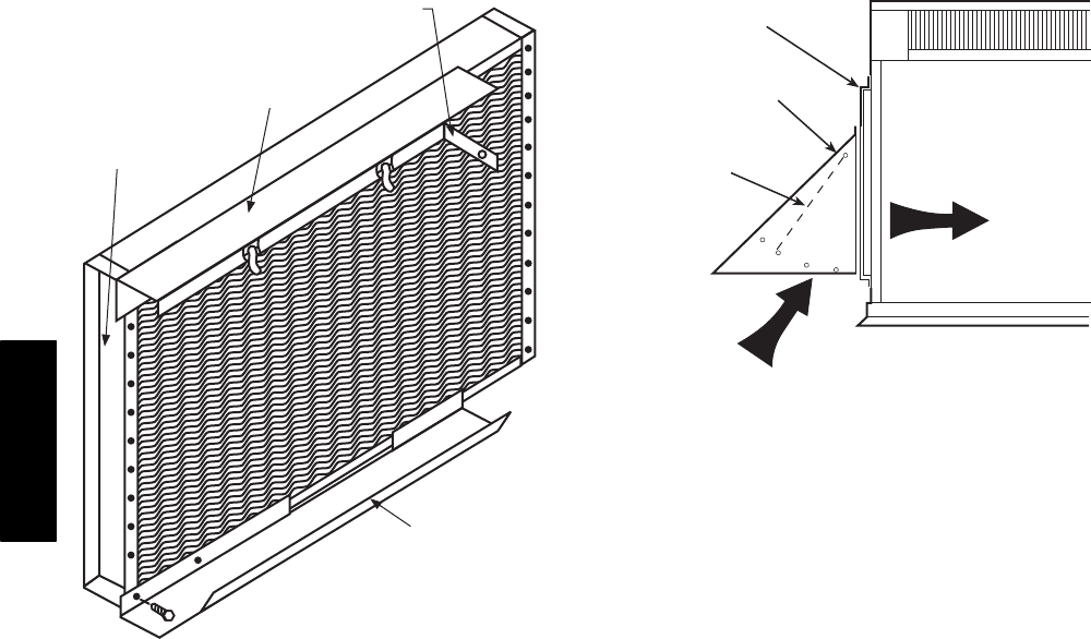
FILTER RACK
EVAPORATOR
COIL
TOP FILTER RACK
BEND FLANGE AT 90°-SCREW TO
DIVIDER WITH 1-IN. SCREW
BOTTOM FILTER
RACK
MANUAL OUTSIDE AIR DAMPER
DAMPER
BLADE
MANUAL OUTSIDE
AIR HOOD
REPLACEMENT
PANEL
50XT
7
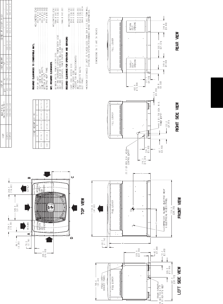
A06594
Fig. 2 -- 50XT024--030 Unit Dimensions
50XT
8
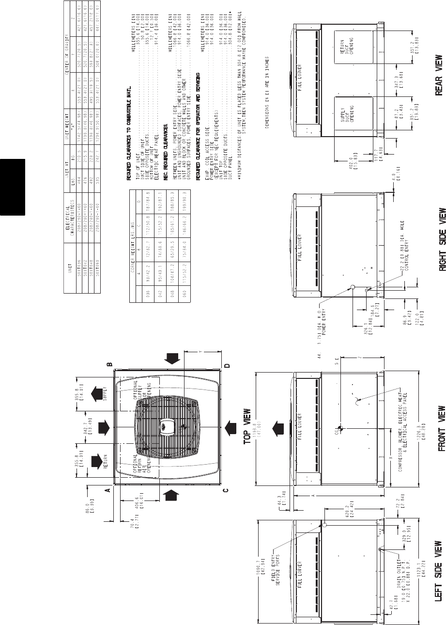
A06595
Fig. 3 -- 50XT036--060 Unit Dimensions
50XT
9
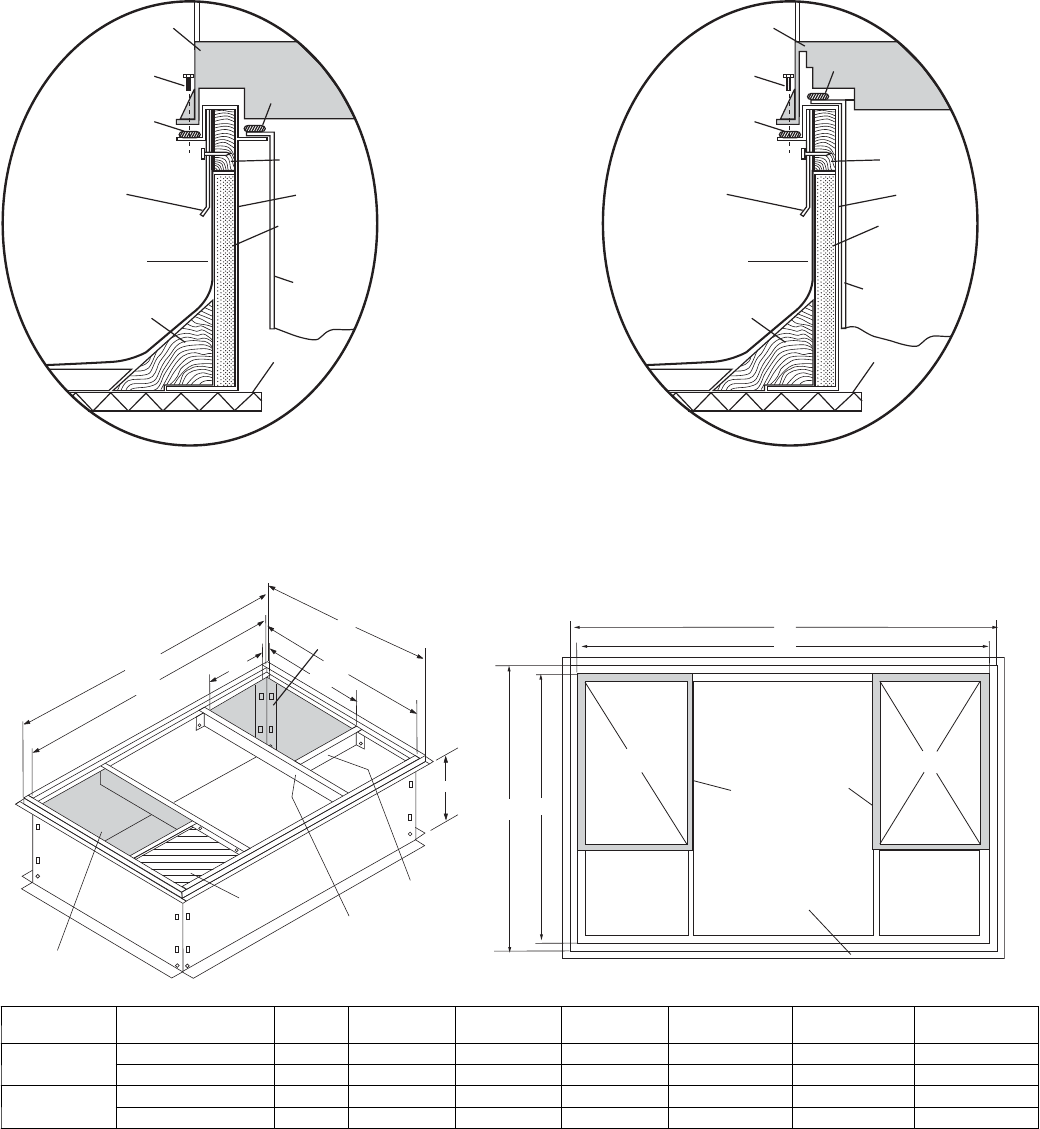
ACCESSORY DIMENSIONS
Gask et around
outer edge
Insulated
deck pan
Gask et around
duct
S/A
R/A
HVAC unit
base
*Gask eting
outer flange
Flashing field
supplied
Roofing material
field supplied
Cant str ip
field supplied
*Provided with roof curb
Roof
Ductwork
field supplied
Insulation (field
supplied)
Roof curb*
Wood nailer*
Gask eting
inner flange*
Scre w
(NO TE A)
Roof Curb for Small Cabinet
Note A: When unit mounting scre w is used,
retainer bra cke t must also be used.
HVAC unit
base
*Gask eting
outer flange
Flashing field
supplied
Roofing material
field supplied
Cant str ip
field supplied
*Provided with roof curb
Roof
Ductwork
field supplied
Insulation (field
supplied)
Roof curb*
Wood nailer*
Gask eting
inner flange*
Scre w
(NOTE A)
Roof Curb for Large Cabinet
Note A: When unit mounting scre w is used,
retainer bra cket must also be used.
A
B Typ.
Supply opening
(B x C)
Long
Support
D
F
Return opening
(B X C)
Insulated
deck pan
Short
Support
C Typ.
G
E
F
G
D
E
A05308
UNIT SIZE CATALOG
NUMBER
A
IN. (MM)
B
IN. (MM)
C
IN. (MM)
D
IN. (MM)
E
IN. (MM)
F
IN. (MM)
G
IN. (MM)
024--030 CPRFCURB006A00 8 (203) 11 (279) 16--1/2 (419) 28--3/4 (730) 30--3/8 (771) 44--5/16 (1126) 45--15/16 (1167)
CPRFCURB007A00 14 (356) 11 (279) 16--1/2 (419) 28--3/4 (730) 30--3/8 (771) 44--5/16 (1126) 45--15/16 (1167)
036--060 CPRFCURB008A00 8 (203) 16--3/16 (411) 17--3/8 (441) 40--1/4 (1022) 41--15/16 (1065) 44--7/16 (1129) 46--1/16 (1169)
CPRFCURB009A00 14 (356) 16--3/16 (411) 17--3/8 (441) 40--1/4 (1022) 41--15/16 (1065) 44--7/16 (1129) 46--1/16 (1169)
NOTES:
1. Roof curb must be set up for unit being installed.
2. Seal strip must be applied, as required, to unit being installed.
3. Roof curb is made of 16--gauge steel.
4. Attach ductwork to curb (flanges of duct rest on curb).
5. Insulated panels: 1--in. (25 mm) thick fiberglass 1 lb. density.
6. When unit mounting screw is used (see Note A), a retainer bracket must be used as well. This bracket must also be used when required by code for hurricaneorseismic
conditions. This bracket is available through Micrometl.
10
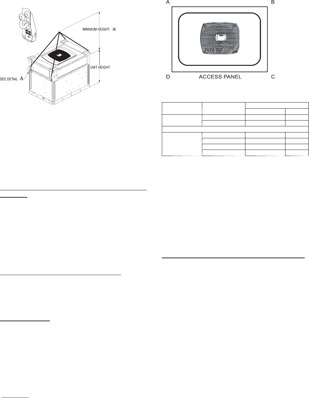
50XT SUGGESTED RIGGING
-in. (914 mm)
DETAIL
A
A06298
A06296
CABINET MODEL RIGGING WT
lb kg
Small 50XT--024 418 190
50XT--030 448 203
Large
50XT--036 469 213
50XT--042 491 223
50XT--048 497 225
50XT--060 548 249
NOTE: See dimensional drawing for corner weight distribution. Corner
weights shown on drawing are based on unit---only weights and do
not include packaging.
SELECTION PROCEDURE
Determine cooling and heating requirements at design
conditions
Given:
REQUIRED COOLING CAPACITY (TC) 34,500 BTUH......
SENSIBLE HEAT CAPACITY (SHC) 24,000 BTUH.........
REQUIRED HEATING CAPACITY (SHC) 36,000 BTUH.....
CONDENSER ENTERING AIR TEMPERATURE 95°F(35°C)
INDOOR--AIR TEMPERATURE 80°F (26.6°C) EDB, 67°F...
(19.4°C) EWB
EVAPORATOR AIR QUANTITY 1200 CFM...............
ELECTRICAL CHARACTERISTICS 230--1--60.............
Select unit based on required cooling capacity
Enter Net Cooling Capacities table at condenser entering
temperature of 95°F(35°C). The 036 unit at 1200 cfm and 67°F
(19.4°C) ewb (entering wet bulb) will provide a total capacity of
34,600 Btuh and a SHC of 24,220 Btuh. Calculate SHC correction,
if required, using Note 4 under Cooling Capacities tables.
Select electric heat
Enter the 036 unit Heating Extended Performance table at 1200
cfm. At 70°F (21.1°C) return indoor air and 20°F(--6.6°C) air
entering outdoor coil, the integrated heating capacity is 16,810
Btuh. (Select integrated heating capacity value since deductions for
outdoor--coil frost and defrosting have already been made. No
correction is required.)
The required heating capacity is 36,000 Btuh. Therefore, at least
19,190 Btuh additional electric heat is required.
Determine additional electric heat capacity in kW.
19,190 Btuh
3414 Btuh/kW
=5.6kWofheatrequired
Enter the Electric Heater table on page 5 for 208/230v,
single--phase, unit. The 7.2--kW heater at 240v most closely
satisfies the heating required. To calculate kW at 230v, multiply the
heater kW by multiplication factor 0.92 found in the Multiplication
Factors table on page 29.
7.2 kW x 0.92 = 6.6 kW
6.6 kW x 3414 Btuh/kW = 22,532 Btuh
Total unit heating capacity is 39,342 Btuh
(16,810 + 22,532).
Select unit that corresponds to power source available
The Electrical Data table shows that the unit is designed to operate
at 208/230--1--60.

11
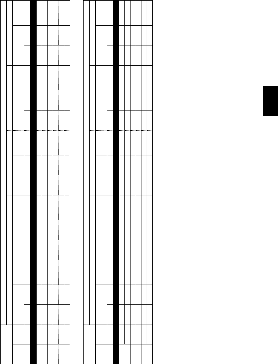
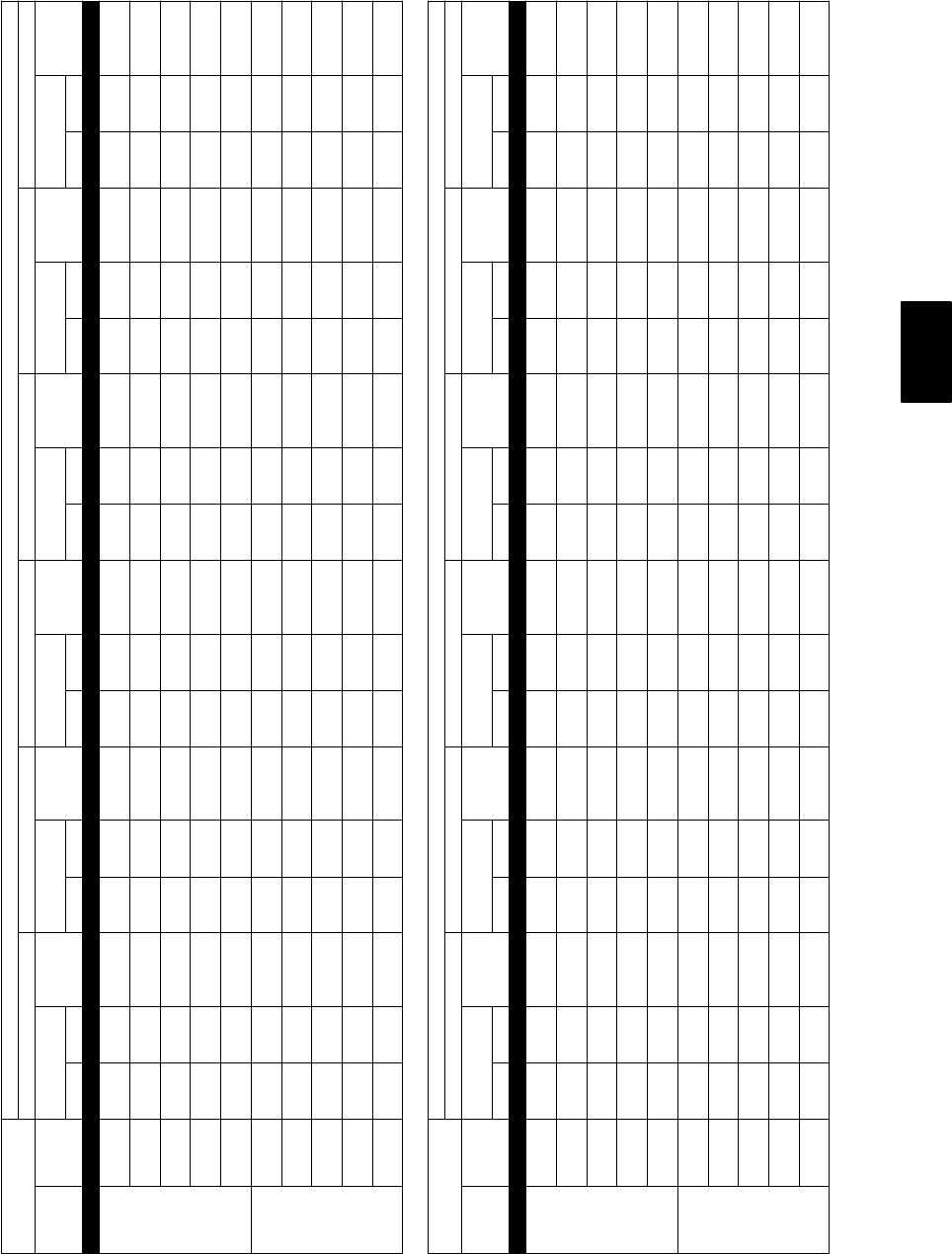
PERFORMANCE DATA--STANDARD ECM INDOOR MOTOR
Cooling Extended Performance Table
50XT024 High Cool
EVAPORATOR
AIR
CONDENSER ENTERING AIR TEMPERATURES _F(_C)
75 (23.8) 85 (29.4) 95 (35) 105 (40.5) 115 (46.1) 125 (51.6)
CFM EWB
_F(_C)
Capacity
MBtuh
Tota l
System
KW
Capacity
MBtuh
Tota l
System
KW
Capacity
MBtuh
Tota l
System
KW
Capacity
MBtuh
Tota l
System
KW
Capacity
MBtuh
Tota l
System
KW
Capacity
MBtuh
Tota l
System
KW
Tota l Sens Total Sens Total Sens Tota l Sens Total Sens Total Sens
700
57
(13.9) 21.77 21.77 1.61 20.88 20.88 1.79 19.95 19.95 2.00 18.94 18.94 2.23 17.86 17.86 2.48 16.66 16.66 2.77
62
(16.7) 22.40 18.69 1.61 21.29 18.21 1.80 20.13 17.70 2.00 18.95 18.95 2.23 17.86 17.86 2.48 16.66 16.66 2.77
63*
(17.2) 22.85 15.18 1.62 21.71 14.70 1.80 20.52 14.21 2.01 19.25 13.70 2.23 17.90 13.16 2.48 16.42 12.58 2.77
67
(19.4) 24.66 15.72 1.64 23.44 15.24 1.83 22.15 14.75 2.03 20.79 14.24 2.26 19.34 13.70 2.51 17.74 13.12 2.79
72
(22.2) 27.16 12.75 1.67 25.83 12.28 1.86 24.42 11.80 2.06 22.94 11.29 2.29 21.33 10.76 2.54 19.57 10.18 2.83
800
57
(13.9) 22.76 22.76 1.64 21.81 21.81 1.82 20.81 20.81 2.03 19.74 19.74 2.26 18.58 18.58 2.51 17.29 17.29 2.80
62
(16.7) 22.97 20.16 1.64 21.84 21.76 1.82 20.81 20.81 2.03 19.74 19.74 2.26 18.58 18.58 2.51 17.29 17.29 2.80
63*
(17.2) 23.39 16.20 1.64 22.19 15.71 1.83 20.94 15.21 2.03 19.62 14.69 2.26 18.22 14.14 2.51 16.69 13.54 2.79
67
(19.4) 25.22 16.81 1.67 23.94 16.32 1.85 22.60 15.82 2.05 21.18 15.30 2.28 19.67 14.74 2.53 18.01 14.14 2.82
72
(22.2) 27.77 13.43 1.70 26.37 12.96 1.88 24.90 12.48 2.09 23.35 11.95 2.31 21.66 11.41 2.57 20.60 11.05 2.57
50XT024 Low Cool
EVAPORATOR
AIR
CONDENSER ENTERING AIR TEMPERATURES _F(_C)
75 (23.8) 85 (29.4) 95 (35) 105 (40.5) 115 (46.1) 125 (51.6)
CFM EWB
_F(_C)
Capacity
MBtuh
Tota l
System
KW
Capacity
MBtuh
Tota l
System
KW
Capacity
MBtuh
Tota l
System
KW
Capacity
MBtuh
Tota l
System
KW
Capacity
MBtuh
Tota l
System
KW
Capacity
MBtuh
Tota l
System
KW
Tota l Sens Total Sens Total Sens Tota l Sens Total Sens Total Sens
525
57
(13.9) 16.65 16.65 1.05 15.95 15.95 1.20 15.21 15.21 1.37 14.40 14.40 1.57 13.52 13.52 1.80 12.55 12.55 2.07
62
(16.7) 17.20 14.47 1.06 16.29 14.07 1.21 15.34 13.65 1.37 14.40 14.40 1.57 13.52 13.52 1.80 12.55 12.55 2.07
63*
(17.2) 17.61 11.75 1.06 16.69 11.3 6 1.21 15.70 10.96 1.38 14.64 10.53 1.57 13.50 10.07 1.80 12.27 9.58 2.06
67
(19.4) 19.23 12.26 1.08 18.23 11.87 1.22 17.18 11.47 1.39 16.05 11.03 1.58 14.83 10.58 1.81 13.50 10.09 2.07
72
(22.2) 21.48 10.05 1.09 20.41 9.66 1.24 19.26 9.26 1.41 18.02 8.84 1.60 16.69 8.39 1.83 15.24 7.90 2.09
600
57
(13.9) 17.52 17.52 1.08 16.77 16.77 1.23 15.96 15.96 1.39 15.10 15.10 1.59 14.15 14.15 1.82 13.11 13.11 2.09
62
(16.7) 17.71 15.66 1.08 16.78 16.75 1.23 15.96 15.96 1.39 15.10 15.10 1.59 14.15 14.15 1.82 13.12 13.12 2.09
63*
(17.2) 18.10 12.58 1.08 17.12 12.18 1.23 16.09 11.76 1.39 14.98 11.32 1.59 13.80 10.85 1.81 12.51 10.35 2.08
67
(19.4) 19.75 13.14 1.09 18.71 12.74 1.24 17.60 12.32 1.41 16.41 11.88 1.60 15.14 11.41 1.83 13.76 10.91 2.09
72
(22.2) 22.06 10.61 1.11 20.93 10.21 1.26 19.72 9.80 1.43 18.41 9.36 1.62 17.03 8.91 1.85 15.51 8.41 2.11
See page 29 for cooling notes.
50XT

12
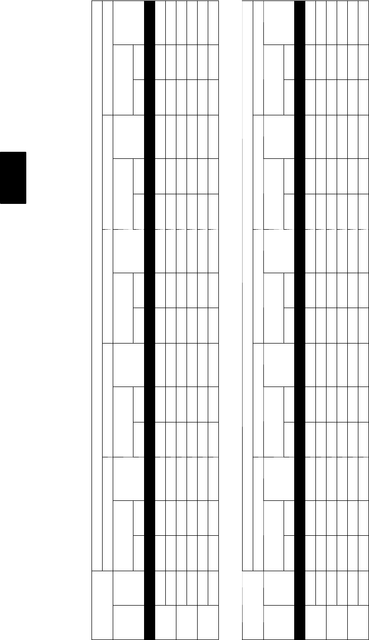
PERFORMANCE DATA--STANDARD ECM INDOOR MOTOR
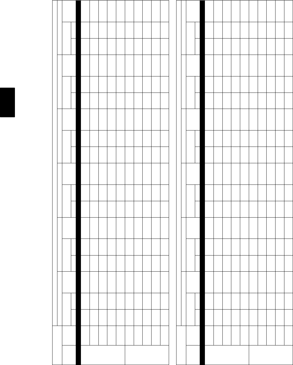
Heating Capacity
50XT024 High
INDOOR AIR OUTDOOR COIL ENTERING AIR TEMPERATURES _F(_C)
--10 (--23.3) 0 (--17.7) 10 (--12.2) 17 (--8.3) 20 (--6.6)
EDB
_F
(_C)
CFM
Capacity
MBtuh
Total
System
KW
Capacity
MBtuh
Total
System
KW
Capacity
MBtuh
Total
System
KW
Capacity
MBtuh
Total
System
KW
Capacity
MBtuh
Total
System
KW
Total Integ Total Integ Total Integ Total Integ Total Integ
60
(15.6)
700 4.21 3.88 1.12 6.40 5.89 1.21 9.38 8.61 1.32 11.90 10.85 1.42 14.22 12.90 1.45
800 4.24 3.90 1.11 6.47 5.95 1.20 9.46 8.69 1.31 11.94 10.89 1.43 14.27 12.94 1.44
70
(21.1)
700 3.97 3.65 1.25 6.12 5.63 1.35 9.01 8.27 1.46 11.51 10.49 1.55 12.36 11.21 1.49
800 4.02 3.70 1.24 6.20 5.71 1.34 9.12 8.37 1.45 11.60 10.58 1.55 12.46 11.30 1.66
80
(26.7)
700 3.77 3.47 1.38 5.83 5.36 1.49 8.62 7.91 1.61 11.03 10.06 1.70 11.85 10.75 1.75
800 3.82 3.51 1.38 5.91 5.43 1.48 8.74 8.02 1.59 11.17 10.19 1.69 12.00 10.88 1.72
50XT024 High Con’t.
INDOOR AIR OUTDOOR COIL ENTERING AIR TEMPERATURES _F(_C)
30 (--1.1) 40 (4.4) 47 (8.3) 50 (10) 60 (15.5)
EDB
_F
(_C)
CFM
Capacity
MBtuh
Total
System
KW
Capacity
MBtuh
Total
System
KW
Capacity
MBtuh
Total
System
KW
Capacity
MBtuh
Total
System
KW
Capacity
MBtuh
Total
System
KW
Total Integ Total Integ Total Integ Total Integ Total Integ
60
(15.6)
700 16.65 14.60 1.58 19.30 19.30 1.69 21.15 21.15 1.75 22.00 22.00 1.78 25.14 25.14 1.92
800 16.84 14.76 1.53 19.36 19.36 1.61 21.27 21.27 1.66 22.16 22.16 1.70 25.40 25.40 1.82
70
(21.1)
700 16.03 14.05 1.62 18.69 18.69 1.86 20.68 20.68 1.95 21.51 21.51 1.98 24.54 24.54 2.11
800 16.25 14.24 1.68 18.95 18.95 1.79 20.80 20.80 1.85 21.65 21.65 1.87 24.82 24.82 2.00
80
(26.7)
700 14.91 13.06 1.89 17.97 17.97 2.03 20.04 20.04 2.14 20.96 20.96 2.20 23.91 23.91 2.32
800 15.10 13.23 1.84 18.27 18.27 1.96 20.30 20.30 2.05 21.13 21.13 2.08 24.20 24.20 2.21
LEGEND
Cap.— Heating Capacity (1000 Btuh) (Includes Indoor--Fan Motor Heat)
db —DryBulb
kW — Total Power Input (Includes Compressor Motor Power Input Outdoor--Fan Motor Input, and Indoor--Fan Motor Input)
rh — Relative Humidity
NOTES:
Integrated capacity is maximum (instantaneous) capacity less the effect of frost on the outdoor coil and the heat required to defrost it.
50XT
13
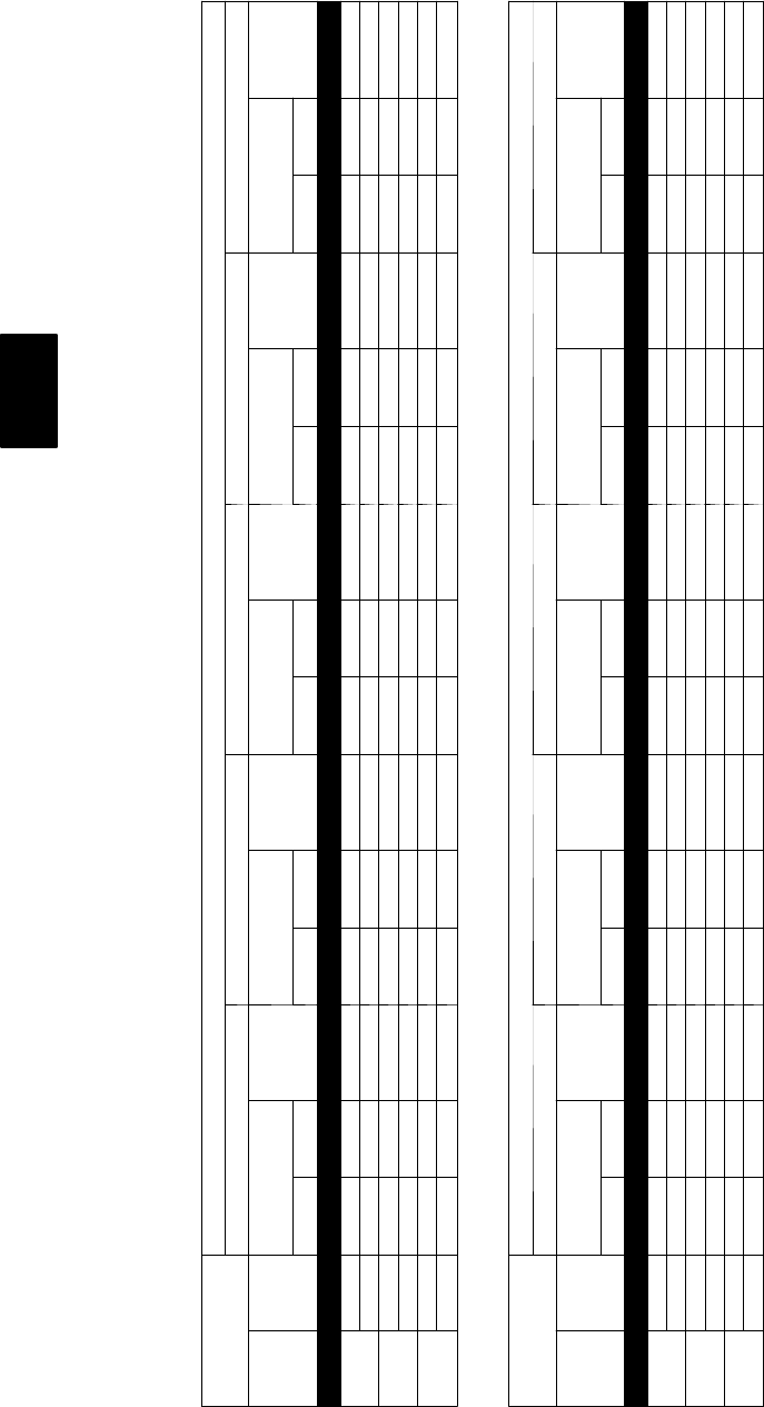
PERFORMANCE DATA--STANDARD ECM INDOOR MOTOR
Heating Capacity
50XT024 Low
INDOOR AIR OUTDOOR COIL ENTERING AIR TEMPERATURES _F(_C)
--10 (--23.3) 0 (--17.7) 10 (--12.2) 17 (--8.3) 20 (--6.6)
EDB
_F
(_C)
CFM
Capacity
MBtuh
Total
System
KW
Capacity
MBtuh
Total
System
KW
Capacity
MBtuh
Total
System
KW
Capacity
MBtuh
Total
System
KW
Capacity
MBtuh
Total
System
KW
Total Integ Total Integ Total Integ Total Integ Total Integ
60
(15.6)
525 2.95 2.72 1.05 4.89 4.50 1.11 7.22 6.63 1.18 8.74 7.97 1.22 9.48 8.60 1.24
600 2.99 2.75 1.04 4.97 4.58 1.09 7.31 6.71 1.17 8.89 8.11 1.20 9.64 8.74 1.22
70
(21.1)
525 2.81 2.59 1.22 4.72 4.34 1.29 6.73 6.18 1.35 8.26 7.53 1.38 8.97 8.14 1.40
600 2.87 2.64 1.21 4.80 4.41 1.28 6.87 6.30 1.34 8.40 7.66 1.37 9.13 8.28 1.38
80
(26.7)
525 2.61 2.41 1.37 4.45 4.09 1.46 6.26 5.75 1.52 7.78 7.10 1.56 8.46 7.68 1.57
600 2.66 2.46 1.36 4.53 4.16 1.44 6.38 5.86 1.51 7.92 7.22 1.54 8.60 7.80 1.56
50XT024 Low Con’t.
INDOOR AIR OUTDOOR COIL ENTERING AIR TEMPERATURES _F(_C)
30 (--1.1) 40 (4.4) 47 (8.3) 50 (10) 60 (15.5)
EDB
_F
(_C)
CFM
Capacity
MBtuh
Total
System
KW
Capacity
MBtuh
Total
System
KW
Capacity
MBtuh
Total
System
KW
Capacity
MBtuh
Total
System
KW
Capacity
MBtuh
Total
System
KW
Total Integ Total Integ Total Integ Total Integ Total Integ
60
(15.6)
525 12.17 10.66 1.30 15.20 15.20 1.37 17.28 17.28 1.41 18.16 18.16 1.44 19.43 19.43 1.44
600 12.37 10.84 1.27 15.22 15.22 1.33 16.79 16.79 1.37 16.85 16.85 1.36 16.78 16.78 1.29
70
(21.1)
525 11.60 10.17 1.46 14.55 14.55 1.54 16.84 16.84 1.61 17.86 17.86 1.64 20.96 20.96 1.71
600 11.80 10.34 1.43 14.80 14.80 1.50 16.80 16.80 1.54 17.64 17.64 1.57 18.39 18.39 1.53
80
(26.7)
525 11.00 9.64 1.64 13.91 13.91 1.72 16.15 16.15 1.79 17.17 17.17 1.83 20.53 20.53 1.91
600 11.21 9.83 1.61 14.16 14.16 1.68 16.40 16.40 1.74 17.36 17.36 1.77 20.33 20.33 1.85
LEGEND
Cap.— Heating Capacity (1000 Btuh) (Includes Indoor--Fan Motor Heat)
db —DryBulb
kW — Total Power Input (Includes Compressor Motor Power Input Outdoor--Fan Motor Input, and Indoor--Fan Motor Input)
rh — Relative Humidity
NOTES:
Integrated capacity is maximum (instantaneous) capacity less the effect of frost on the outdoor coil and the heat required to defrost it.
50XT
14
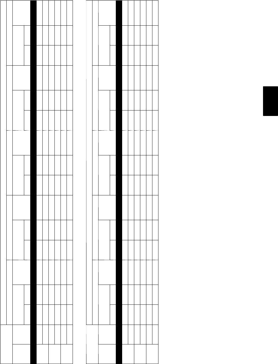
PERFORMANCE DATA--STANDARD ECM INDOOR MOTOR
Cooling Extended Performance Table
50XT030 High Cool
EVAPORATOR
AIR
CONDENSER ENTERING AIR TEMPERATURES _F(_C)
75 (23.8) 85 (29.4) 95 (35) 105 (40.5) 115 (46.1) 125 (51.6)
CFM EWB
_F(_C)
Capacity
MBtuh
Tota l
System
KW
Capacity
MBtuh
Tota l
System
KW
Capacity
MBtuh
Tota l
System
KW
Capacity
MBtuh
Tota l
System
KW
Capacity
MBtuh
Tota l
System
KW
Capacity
MBtuh
Tota l
System
KW
Tota l Sens Total Sens Total Sens Tota l Sens Total Sens Total Sens
875 57
(13.9)
27.90 27.90 2.05 26.73 26.73 2.27 25.47 25.47 2.52 24.09 24.09 2.79 22.56 22.56 3.10 20.81 20.81 3.44
62
(16.7)
28.72 23.85 2.06 27.25 23.21 2.28 25.70 22.53 2.52 24.09 24.09 2.79 22.56 22.56 3.10 20.81 20.81 3.44
63*
(17.2)
29.28 19.34 2.07 27.78 18.72 2.29 26.18 18.07 2.53 24.46 17.38 2.80 22.58 16.64 3.10 20.50 15.82 3.43
67
(19.4)
31.48 19.99 2.10 29.85 19.36 2.32 28.11 18.70 2.56 26.23 18.00 2.83 24.19 17.25 3.13 21.92 16.42 3.47
72
(22.2)
34.49 16.13 2.14 32.69 15.50 2.36 30.77 14.85 2.61 28.70 14.15 2.88 26.43 13.40 3.18 26.31 13.36 3.19
1000 57
(13.9)
29.10 29.10 2.09 27.84 27.84 2.32 26.48 26.48 2.56 25.00 25.00 2.84 23.34 23.34 3.15 21.47 21.47 3.49
62
(16.7)
29.40 25.68 2.10 27.90 27.75 2.32 26.48 26.48 2.56 25.00 25.00 2.84 23.34 23.34 3.15 21.47 21.47 3.49
63*
(17.2)
29.91 20.61 2.10 28.33 19.98 2.32 26.66 19.31 2.57 24.86 18.60 2.83 22.90 17.84 3.13 20.75 17.00 3.47
67
(19.4)
32.13 21.34 2.14 30.42 20.69 2.36 28.60 20.02 2.60 26.64 19.30 2.87 24.51 18.53 3.17 22.47 16.98 3.51
72
(22.2)
35.18 16.96 2.18 33.29 16.32 2.40 31.27 15.65 2.65 29.11 14.94 2.92 26.76 14.18 3.22 24.19 13.36 3.55
50XT030 Low Cool
EVAPORATOR
AIR
CONDENSER ENTERING AIR TEMPERATURES _F(_C)
75 (23.8) 85 (29.4) 95 (35) 105 (40.5) 115 (46.1) 125 (51.6)
CFM EWB
_F(_C)
Capacity
MBtuh
Tota l
System
KW
Capacity
MBtuh
Tota l
System
KW
Capacity
MBtuh
Tota l
System
KW
Capacity
MBtuh
Tota l
System
KW
Capacity
MBtuh
Tota l
System
KW
Capacity
MBtuh
Tota l
System
KW
Tota l Sens Total Sens Total Sens Tota l Sens Total Sens Total Sens
615
57
(13.9) 20.32 20.32 1.29 19.50 19.50 1.48 18.60 18.60 1.70 17.60 17.60 1.95 16.20 16.20 2.21 15.23 15.23 2.58
62
(16.7) 21.08 17.65 1.30 20.01 17.18 1.49 18.86 16.67 1.70 17.62 17.58 1.95 16.49 16.49 2.24 15.23 15.23 2.58
63*
(17.2) 21.55 14.40 1.30 20.47 13.94 1.49 19.28 13.44 1.70 17.99 12.90 1.95 16.58 12.33 2.24 15.02 11.71 2.58
67
(19.4) 23.40 14.96 1.32 22.22 14.49 1.51 20.93 13.99 1.72 19.51 13.44 1.97 17.97 12.85 2.26 16.26 12.24 2.60
72
(22.2) 25.95 12.26 1.35 24.65 11.79 1.53 23.20 11.28 1.75 21.63 10.73 2.00 19.91 10.14 2.28 18.01 9.51 2.62
700
57
(13.9) 21.32 21.32 1.31 20.44 20.44 1.50 19.46 19.46 1.72 18.38 18.38 1.97 17.17 17.17 2.26 15.82 15.82 2.60
62
(16.7) 21.67 19.04 1.31 20.56 18.54 1.50 19.46 19.46 1.72 18.38 18.38 1.97 17.17 17.17 2.26 15.82 15.82 2.60
63*
(17.2) 22.13 15.36 1.32 20.98 14.89 1.51 19.74 14.38 1.72 18.38 13.83 1.97 16.90 13.24 2.26 15.28 12.60 2.60
67
(19.4) 24.00 15.98 1.34 22.76 15.50 1.53 21.40 14.98 1.74 19.91 14.42 1.99 18.29 13.82 2.28 16.52 13.17 2.61
72
(22.2) 26.61 12.91 1.36 25.22 12.42 1.55 23.71 11.90 1.76 22.06 11.34 2.01 20.25 10.74 2.30 18.28 10.09 2.63
See page 29 for cooling notes.
50XT
15
PERFORMANCE DATA--STANDARD ECM INDOOR MOTOR
Heating Capacity
50XT030 High
INDOOR AIR OUTDOOR COIL ENTERING AIR TEMPERATURES _F(_C)
--10 (--23.3) 0 (--17.7) 10 (--12.2) 17 (--8.3) 20 (--6.6)
EDB
_F
(_C)
CFM
Capacity
MBtuh
Total
System
KW
Capacity
MBtuh
Total
System
KW
Capacity
MBtuh
Total
System
KW
Capacity
MBtuh
Total
System
KW
Capacity
MBtuh
Total
System
KW
Total Integ Total Integ Total Integ Total Integ Total Integ
60
(15.6)
875 7.07 6.51 1.56 9.35 8.60 1.64 12.08 11.09 1.72 14.34 13.07 1.78 15.42 13.99 1.81
1000 7.16 6.59 1.56 9.46 8.70 1.64 12.23 11.23 1.71 14.51 13.23 1.77 15.61 14.16 1.79
70
(21.1)
875 6.74 6.20 1.73 9.00 8.28 1.82 11.66 10.70 1.91 13.82 12.60 1.97 14.85 13.46 2.00
1000 6.84 6.29 1.73 9.12 8.39 1.82 11.80 10.83 1.90 14.00 12.76 1.95 15.04 13.64 1.98
80
(26.7)
875 6.31 5.81 1.90 8.56 7.88 2.00 11.20 10.28 2.10 13.30 12.13 2.17 14.28 12.95 2.20
1000 6.42 5.91 1.90 8.69 8.00 2.00 11.35 10.42 2.09 13.48 12.29 2.15 14.46 13.11 2.18
50XT030 High Con’t.
INDOOR AIR OUTDOOR COIL ENTERING AIR TEMPERATURES _F(_C)
30 (--1.1) 40 (4.4) 47 (8.3) 50 (10) 60 (15.5)
EDB
_F
(_C)
CFM
Capacity
MBtuh
Total
System
KW
Capacity
MBtuh
Total
System
KW
Capacity
MBtuh
Total
System
KW
Capacity
MBtuh
Total
System
KW
Capacity
MBtuh
Total
System
KW
Total Integ Total Integ Total Integ Total Integ Total Integ
60
(15.6)
875 19.48 17.07 1.91 24.32 24.32 2.04 28.09 28.09 2.08 29.61 29.61 2.12 35.99 35.99 2.18
1000 19.75 17.31 1.89 24.63 24.63 2.02 28.28 28.28 2.15 30.05 30.05 2.19 36.32 36.32 2.32
70
(21.1)
875 18.76 16.44 2.11 23.39 23.39 2.23 27.23 27.23 2.34 29.07 29.07 2.40 35.34 35.34 2.46
1000 19.03 16.67 2.08 23.75 23.75 2.20 27.60 27.60 2.31 29.24 29.24 2.34 35.85 35.85 2.54
80
(26.7)
875 18.00 15.77 2.31 22.48 22.48 2.44 26.17 26.17 2.56 27.94 27.94 2.62 34.42 34.42 2.70
1000 18.32 16.05 2.28 22.83 22.83 2.40 26.59 26.59 2.51 28.38 28.38 2.57 34.50 34.50 2.82
LEGEND
Cap.— Heating Capacity (1000 Btuh) (Includes Indoor--Fan Motor Heat)
db —DryBulb
kW — Total Power Input (Includes Compressor Motor Power Input Outdoor--Fan Motor Input, and Indoor--Fan Motor Input)
rh — Relative Humidity
NOTES:
Integrated capacity is maximum (instantaneous) capacity less the effect of frost on the outdoor coil and the heat required to defrost it.
50XT

16
PERFORMANCE DATA--STANDARD ECM INDOOR MOTOR
Heating Capacity
50XT030 Low
INDOOR AIR OUTDOOR COIL ENTERING AIR TEMPERATURES _F(_C)
--10 (--23.3) 0 (--17.7) 10 (--12.2) 17 (--8.3) 20 (--6.6)
EDB
_F
(_C)
CFM
Capacity
MBtuh
Total
System
KW
Capacity
MBtuh
Total
System
KW
Capacity
MBtuh
Total
System
KW
Capacity
MBtuh
Total
System
KW
Capacity
MBtuh
Total
System
KW
Total Integ Total Integ Total Integ Total Integ Total Integ
60
(15.6)
615 3.77 3.47 1.12 5.75 5.29 1.20 8.06 7.40 1.27 9.90 9.03 1.32 10.75 9.75 1.34
700 3.81 3.51 1.12 5.82 5.36 1.19 8.16 7.49 1.25 10.01 9.13 1.29 10.87 9.86 1.31
70
(21.1)
615 3.34 3.07 1.29 5.44 5.00 1.38 7.66 7.03 1.46 9.47 8.64 1.51 10.31 9.35 1.53
700 3.42 3.15 1.29 5.55 5.10 1.37 7.75 7.11 1.44 9.60 8.75 1.48 10.45 9.47 1.50
80
(26.7)
615 2.85 2.62 1.47 4.84 4.45 1.57 7.16 6.57 1.65 8.97 8.18 1.71 9.80 8.89 1.73
700 2.91 2.68 1.47 4.93 4.54 1.56 7.27 6.67 1.63 9.10 8.30 1.68 9.94 9.02 1.70
50XT030 Low Con’t.
INDOOR AIR OUTDOOR COIL ENTERING AIR TEMPERATURES _F(_C)
30 (--1.1) 40 (4.4) 47 (8.3) 50 (10) 60 (15.5)
EDB
_F
(_C)
CFM
Capacity
MBtuh
Total
System
KW
Capacity
MBtuh
Total
System
KW
Capacity
MBtuh
Total
System
KW
Capacity
MBtuh
Total
System
KW
Capacity
MBtuh
Total
System
KW
Total Integ Total Integ Total Integ Total Integ Total Integ
60
(15.6)
615 13.95 12.23 1.41 17.78 17.78 1.50 20.83 20.83 1.57 22.25 22.25 1.61 27.83 27.83 1.75
700 14.14 12.39 1.37 18.04 18.04 1.45 21.17 21.17 1.51 22.64 22.64 1.54 28.00 28.00 1.62
70
(21.1)
615 13.39 11.73 1.61 17.11 17.11 1.70 20.08 20.08 1.78 21.45 21.45 1.81 26.70 26.70 1.96
700 13.58 11.90 1.57 17.39 17.39 1.65 20.40 20.40 1.71 21.80 21.80 1.74 27.26 27.26 1.87
80
(26.7)
615 12.86 11.27 1.82 16.41 16.41 1.92 19.37 19.37 2.01 20.70 20.70 2.05 25.66 25.66 2.20
700 13.03 11.42 1.78 16.66 16.66 1.86 19.66 19.66 1.93 21.02 21.02 1.96 26.16 26.16 2.09
LEGEND
Cap.— Heating Capacity (1000 Btuh) (Includes Indoor--Fan Motor Heat)
db —DryBulb
kW — Total Power Input (Includes Compressor Motor Power Input Outdoor--Fan Motor Input, and Indoor--Fan Motor Input)
rh — Relative Humidity
NOTES:
Integrated capacity is maximum (instantaneous) capacity less the effect of frost on the outdoor coil and the heat required to defrost it.
50XT
17
PERFORMANCE DATA--STANDARD ECM INDOOR MOTOR
Cooling Extended Performance Table
50XT036 High Cool
EVAPORATOR
AIR
CONDENSER ENTERING AIR TEMPERATURES _F(_C)
75 (23.8) 85 (29.4) 95 (35) 105 (40.5) 115 (46.1) 125 (51.6)
CFM EWB
_F(_C)
Capacity
MBtuh
Tota l
System
KW
Capacity
MBtuh
Tota l
System
KW
Capacity
MBtuh
Tota l
System
KW
Capacity
MBtuh
Tota l
System
KW
Capacity
MBtuh
Tota l
System
KW
Capacity
MBtuh
Tota l
System
KW
Tota l Sens Total Sens Total Sens Tota l Sens Total Sens Total Sens
1050
57
(13.9) 33.64 33.64 2.28 32.32 32.32 2.53 30.90 30.90 2.81 29.36 29.36 3.11 27.65 27.65 3.46 25.71 25.71 3.84
62
(16.7) 34.47 28.72 2.29 32.83 28.00 2.54 31.11 27.24 2.81 29.36 29.36 3.11 27.65 27.65 3.46 25.71 25.71 3.84
63*
(17.2) 35.12 23.25 2.29 33.44 22.56 2.54 31.65 21.83 2.81 29.73 21.07 3.12 27.64 20.25 3.45 25.33 19.35 3.83
67
(19.4) 37.76 24.04 2.32 35.94 23.34 2.57 34.00 22.61 2.84 31.91 21.83 3.15 29.65 21.00 3.49 27.14 20.10 3.87
72
(22.2) 42.16 18.41 2.37 40.12 17.73 2.62 37.93 17.01 2.90 35.58 16.24 3.20 33.02 15.43 3.54 30.21 14.53 3.92
1200
57
(13.9) 35.06 35.06 2.32 33.64 33.64 2.58 32.12 32.12 2.85 30.46 30.46 3.16 28.63 28.63 3.50 26.56 26.56 3.89
62
(16.7) 35.29 30.91 2.33 33.64 33.64 2.58 32.12 32.12 2.85 30.46 30.46 3.16 28.63 28.63 3.50 26.56 26.56 3.89
63*
(17.2) 35.86 24.79 2.33 34.09 24.08 2.58 32.22 23.34 2.85 30.23 22.56 3.15 28.05 21.71 3.49 25.66 20.78 3.87
67
(19.4) 38.52 25.68 2.36 36.62 24.97 2.61 34.60 24.22 2.88 32.43 23.43 3.19 30.06 22.57 3.53 27.47 21.64 3.90
72
(22.2) 42.99 19.31 2.41 40.85 18.61 2.66 38.57 17.87 2.93 36.13 17.09 3.24 33.48 16.25 3.58 30.56 15.35 3.96
50XT036 Low Cool
EVAPORATOR
AIR
CONDENSER ENTERING AIR TEMPERATURES _F(_C)
75 (23.8) 85 (29.4) 95 (35) 105 (40.5) 115 (46.1) 125 (51.6)
CFM EWB
_F(_C)
Capacity
MBtuh
Tota l
System
KW
Capacity
MBtuh
Tota l
System
KW
Capacity
MBtuh
Tota l
System
KW
Capacity
MBtuh
Tota l
System
KW
Capacity
MBtuh
Tota l
System
KW
Capacity
MBtuh
Tota l
System
KW
Tota l Sens Total Sens Total Sens Tota l Sens Total Sens Total Sens
745
57
(13.9) 23.27 23.27 1.46 22.34 22.34 1.65 21.31 21.31 1.87 20.19 20.19 2.12 18.95 18.95 2.41 17.58 17.58 2.76
62
(16.7) 23.91 20.06 1.46 22.70 19.54 1.65 21.41 18.97 1.87 20.19 20.19 2.12 18.95 18.95 2.41 17.58 17.58 2.76
63*
(17.2) 24.46 16.28 1.47 23.21 15.77 1.66 21.87 15.23 1.87 20.42 14.65 2.12 18.85 14.03 2.41 17.14 13.36 2.75
67
(19.4) 26.63 16.96 1.48 25.29 16.45 1.67 23.85 15.90 1.89 22.28 15.32 2.14 20.58 14.69 2.43 18.72 14.02 2.77
72
(22.2) 29.67 13.86 1.51 28.20 13.35 1.70 26.61 12.81 1.91 24.89 12.23 2.16 23.01 11.60 2.45 20.96 10.93 2.79
850
57
(13.9) 24.45 24.45 1.48 23.43 23.43 1.67 22.33 22.33 1.89 21.11 21.11 2.14 19.80 19.80 2.44 18.32 18.32 2.78
62
(16.7) 24.61 21.68 1.48 23.43 23.43 1.67 22.33 22.33 1.89 21.12 21.12 2.14 19.80 19.80 2.44 18.32 18.32 2.78
63*
(17.2) 25.11 17.42 1.49 23.80 16.89 1.68 22.39 16.34 1.89 20.88 15.74 2.14 19.24 15.10 2.43 17.46 14.42 2.77
67
(19.4) 27.33 18.17 1.50 25.92 17.64 1.69 24.40 17.08 1.91 22.76 16.48 2.15 20.99 15.84 2.44 19.06 15.15 2.78
72
(22.2) 30.44 14.64 1.53 28.89 14.12 1.71 27.21 13.55 1.93 25.40 12.96 2.17 23.45 12.33 2.46 21.30 11.65 2.80
See page 29 for cooling notes.
50XT

18
PERFORMANCE DATA--STANDARD ECM INDOOR MOTOR
Heating Capacity
50XT036 High
INDOOR AIR OUTDOOR COIL ENTERING AIR TEMPERATURES _F(_C)
--10 (--23.3) 0 (--17.7) 10 (--12.2) 17 (--8.3) 20 (--6.6)
EDB
_F
(_C)
CFM
Capacity
MBtuh
Total
System
KW
Capacity
MBtuh
Total
System
KW
Capacity
MBtuh
Total
System
KW
Capacity
MBtuh
Total
System
KW
Capacity
MBtuh
Total
System
KW
Total Integ Total Integ Total Integ Total Integ Total Integ
60
(15.6)
1050 8.62 7.93 1.43 11.33 10.43 1.60 14.73 13.52 1.78 17.57 16.02 1.92 18.91 17.15 1.99
1200 8.70 8.01 1.43 11.45 10.53 1.59 14.88 13.66 1.77 17.76 16.19 1.90 19.11 17.33 1.97
70
(21.1)
1050 8.34 7.68 1.59 11.02 10.14 1.77 14.26 13.09 1.97 16.99 15.49 2.12 18.32 16.61 2.19
1200 8.44 7.77 1.59 11.14 10.25 1.77 14.42 13.24 1.96 17.20 15.68 2.10 18.53 16.81 2.17
80
(26.7)
1050 7.96 7.32 1.74 10.60 9.76 1.95 13.78 12.65 2.17 16.38 14.93 2.33 17.63 15.99 2.40
1200 8.07 7.43 1.74 10.74 9.88 1.94 13.93 12.79 2.15 16.59 15.12 2.31 17.86 16.19 2.38
50XT036 High Con’t.
INDOOR AIR OUTDOOR COIL ENTERING AIR TEMPERATURES _F(_C)
30 (--1.1) 40 (4.4) 47 (8.3) 50 (10) 60 (15.5)
EDB
_F
(_C)
CFM
Capacity
MBtuh
Total
System
KW
Capacity
MBtuh
Total
System
KW
Capacity
MBtuh
Total
System
KW
Capacity
MBtuh
Total
System
KW
Capacity
MBtuh
Total
System
KW
Total Integ Total Integ Total Integ Total Integ Total Integ
60
(15.6)
1050 23.95 20.99 2.22 29.99 29.99 2.51 34.51 34.51 2.69 36.57 36.57 2.79 43.09 43.09 3.12
1200 24.20 21.21 2.20 30.20 30.20 2.45 34.82 34.82 2.67 36.95 36.95 2.74 43.39 43.39 2.88
70
(21.1)
1050 23.16 20.29 2.44 28.99 28.99 2.73 33.82 33.82 2.98 35.98 35.98 3.08 42.90 42.90 3.44
1200 23.44 20.54 2.41 29.28 29.28 2.71 33.60 33.60 2.90 35.59 35.59 3.00 43.10 43.10 3.30
80
(26.7)
1050 22.38 19.61 2.67 28.03 28.03 2.99 32.65 32.65 3.24 34.87 34.87 3.37 42.66 42.66 3.75
1200 22.66 19.86 2.64 28.36 28.36 2.94 33.00 33.00 3.21 34.97 34.97 3.29 42.80 42.80 3.69
50XT

19
PERFORMANCE DATA--STANDARD ECM INDOOR MOTOR
Heating Capacity
50XT036 Low
INDOOR AIR OUTDOOR COIL ENTERING AIR TEMPERATURES _F(_C)
--10 (--23.3) 0 (--17.7) 10 (--12.2) 17 (--8.3) 20 (--6.6)
EDB
_F
(_C)
CFM
Capacity
MBtuh
Total
System
KW
Capacity
MBtuh
Total
System
KW
Capacity
MBtuh
Total
System
KW
Capacity
MBtuh
Total
System
KW
Capacity
MBtuh
Total
System
KW
Total Integ Total Integ Total Integ Total Integ Total Integ
60
(15.6)
745 3.84 3.53 1.62 6.63 6.10 1.68 9.48 8.70 1.72 11.69 10.66 1.74 12.69 11.51 1.75
850 3.91 3.60 1.62 6.71 6.17 1.67 9.61 8.82 1.70 11.84 10.80 1.71 12.85 11.66 1.72
70
(21.1)
745 3.10 2.86 1.82 5.88 5.41 1.89 8.83 8.10 1.93 11.03 10.06 1.95 12.02 10.90 1.96
850 3.23 2.98 1.82 6.01 5.53 1.89 8.98 8.24 1.92 11.20 10.21 1.93 12.20 11.07 1.94
80
(26.7)
745 2.22 2.05 2.03 5.00 4.60 2.10 8.01 7.35 2.15 10.24 9.33 2.18 11.23 10.18 2.19
850 2.34 2.16 2.04 5.12 4.71 2.11 8.17 7.49 2.14 10.42 9.50 2.16 11.42 10.36 2.16
50XT036 Low Con’t.
INDOOR AIR OUTDOOR COIL ENTERING AIR TEMPERATURES _F(_C)
30 (--1.1) 40 (4.4) 47 (8.3) 50 (10) 60 (15.5)
EDB
_F
(_C)
CFM
Capacity
MBtuh
Total
System
KW
Capacity
MBtuh
Total
System
KW
Capacity
MBtuh
Total
System
KW
Capacity
MBtuh
Total
System
KW
Capacity
MBtuh
Total
System
KW
Total Integ Total Integ Total Integ Total Integ Total Integ
60
(15.6)
745 16.25 14.24 1.78 20.33 20.33 1.81 23.56 23.56 1.84 25.01 25.01 1.85 30.27 30.27 1.90
850 16.46 14.42 1.74 20.70 20.70 1.76 23.96 23.96 1.78 25.46 25.46 1.78 30.88 30.88 1.82
70
(21.1)
745 15.55 13.62 1.99 19.45 19.45 2.02 22.61 22.61 2.05 24.02 24.02 2.06 29.09 29.09 2.11
850 15.78 13.82 1.95 19.78 19.78 1.97 23.00 23.00 1.98 24.44 24.44 1.99 29.68 29.68 2.02
80
(26.7)
745 14.74 12.91 2.22 18.60 18.60 2.26 21.56 21.56 2.28 22.94 22.94 2.29 27.95 27.95 2.35
850 14.98 13.13 2.18 18.90 18.90 2.20 21.95 21.95 2.21 23.44 23.44 2.22 28.50 28.50 2.25
LEGEND
Cap.— Heating Capacity (1000 Btuh) (Includes Indoor--Fan Motor Heat)
db —DryBulb
kW — Total Power Input (Includes Compressor Motor Power Input Outdoor--Fan Motor Input, and Indoor--Fan Motor Input)
rh — Relative Humidity
NOTES:
Integrated capacity is maximum (instantaneous) capacity less the effect of frost on the outdoor coil and the heat required to defrost it.
50XT

20
PERFORMANCE DATA--STANDARD ECM INDOOR MOTOR
Cooling Extended Performance Table
50XT042 High Cool
EVAPORATOR
AIR
CONDENSER ENTERING AIR TEMPERATURES _F(_C)
75 (23.8) 85 (29.4) 95 (35) 105 (40.5) 115 (46.1) 125 (51.6)
CFM EWB
_F(_C)
Capacity
MBtuh
Tota l
System
KW
Capacity
MBtuh
Tota l
System
KW
Capacity
MBtuh
Tota l
System
KW
Capacity
MBtuh
Tota l
System
KW
Capacity
MBtuh
Tota l
System
KW
Capacity
MBtuh
Tota l
System
KW
Tota l Sens Total Sens Total Sens Tota l Sens Total Sens Total Sens
1225
57
(13.9) 40.34 40.34 2.76 38.56 38.56 3.03 36.60 36.60 3.32 35.21 35.21 3.58 32.79 32.79 3.93 29.04 29.04 4.37
62
(16.7) 41.24 37.05 2.77 39.06 36.02 3.04 36.71 36.39 3.33 35.21 35.21 3.57 32.79 32.79 3.93 29.04 29.04 4.37
63*
(17.2) 42.00 29.94 2.78 39.74 28.96 3.05 37.29 27.90 3.34 35.56 27.16 3.58 32.52 25.89 3.92 28.29 24.13 4.35
67
(19.4) 45.04 30.93 2.84 42.59 29.93 3.10 39.90 28.85 3.39 38.03 28.11 3.63 34.81 26.85 3.98 30.12 25.04 4.40
72
(22.2) 49.21 24.77 2.91 46.48 23.77 3.17 43.50 22.69 3.46 44.33 22.99 3.52 41.24 21.88 3.87 32.75 18.96 4.47
1400
57
(13.9) 41.96 41.96 2.82 40.04 40.04 3.10 37.92 37.92 3.39 36.46 36.46 3.64 33.86 33.86 4.00 29.82 29.82 4.43
62
(16.7) 42.17 39.80 2.83 40.04 40.04 3.10 37.92 37.92 3.39 36.46 36.46 3.64 33.86 33.86 4.00 29.82 29.82 4.43
63*
(17.2) 42.81 31.90 2.84 40.45 30.89 3.10 37.88 29.81 3.39 36.05 29.03 3.63 31.99 27.35 4.03 28.59 25.92 4.40
67
(19.4) 45.87 33.01 2.89 43.30 31.98 3.15 40.50 30.88 3.44 38.65 30.16 3.69 35.36 28.88 4.03 30.38 26.96 4.45
72
(22.2) 50.09 26.04 2.96 47.23 25.02 3.23 44.13 23.92 3.51 45.09 24.26 3.58 41.83 23.12 3.93 32.98 20.13 4.51
50XT042 Low Cool
EVAPORATOR
AIR
CONDENSER ENTERING AIR TEMPERATURES _F(_C)
75 (23.8) 85 (29.4) 95 (35) 105 (40.5) 115 (46.1) 125 (51.6)
CFM EWB
_F(_C)
Capacity
MBtuh
Tota l
System
KW
Capacity
MBtuh
Tota l
System
KW
Capacity
MBtuh
Tota l
System
KW
Capacity
MBtuh
Tota l
System
KW
Capacity
MBtuh
Tota l
System
KW
Capacity
MBtuh
Tota l
System
KW
Tota l Sens Total Sens Total Sens Tota l Sens Total Sens Total Sens
855
57
(13.9) 28.20 28.20 1.89 27.00 27.00 2.11 25.67 25.67 2.35 24.16 24.16 2.63 22.43 22.43 2.94 20.50 20.50 3.29
62
(16.7) 28.99 24.09 1.89 27.46 23.43 2.11 26.46 22.99 2.31 24.16 24.16 2.63 22.43 22.43 2.94 20.48 20.48 3.29
63*
(17.2) 29.61 19.56 1.89 28.04 18.92 2.11 26.32 18.23 2.35 24.41 17.47 2.63 22.29 16.64 2.95 19.93 15.73 3.30
67
(19.4) 32.05 20.31 1.89 30.33 19.65 2.11 28.43 18.94 2.35 26.33 18.16 2.62 23.99 17.30 2.92 21.52 16.42 3.28
72
(22.2) 35.41 16.51 1.89 33.47 15.84 2.10 31.36 15.12 2.34 31.76 15.26 2.28 26.40 13.49 2.90 24.07 12.74 3.25
975
57
(13.9) 29.53 29.53 1.90 28.23 28.23 2.12 26.78 26.78 2.36 25.14 25.14 2.64 23.27 23.27 2.95 21.29 21.29 3.29
62
(16.7) 29.77 25.99 1.90 28.23 28.23 2.12 26.78 26.78 2.36 25.14 25.14 2.64 23.27 23.27 2.95 21.29 21.29 3.29
63*
(17.2) 30.34 20.89 1.90 28.69 20.23 2.12 26.88 19.52 2.37 24.87 18.73 2.64 22.66 17.88 2.96 20.20 16.93 3.31
67
(19.4) 32.81 21.71 1.91 31.00 21.04 2.12 29.00 20.30 2.36 28.00 19.93 2.59 24.36 18.62 2.93 21.97 17.76 3.29
72
(22.2) 36.21 17.40 1.91 34.17 16.72 2.12 31.95 16.00 2.35 31.03 15.68 2.58 30.23 15.42 2.60 24.42 13.57 3.26
See page 29 for cooling notes.
50XT

21
PERFORMANCE DATA--STANDARD ECM INDOOR MOTOR
Heating Capacity
50XT042 High
INDOOR AIR OUTDOOR COIL ENTERING AIR TEMPERATURES _F(_C)
--10 (--23.3) 0 (--17.7) 10 (--12.2) 17 (--8.3) 20 (--6.6)
EDB
_F
(_C)
CFM
Capacity
MBtuh
Total
System
KW
Capacity
MBtuh
Total
System
KW
Capacity
MBtuh
Total
System
KW
Capacity
MBtuh
Total
System
KW
Capacity
MBtuh
Total
System
KW
Total Integ Total Integ Total Integ Total Integ Total Integ
60
(15.6)
1225 10.65 9.80 2.06 13.99 12.87 2.19 17.85 16.39 2.32 21.02 19.17 2.41 22.53 20.43 2.46
1400 10.79 9.92 2.08 14.15 13.02 2.20 18.04 16.56 2.32 21.26 19.39 2.41 22.79 20.67 2.45
70
(21.1)
1225 10.16 9.34 2.28 13.49 12.42 2.42 17.32 15.89 2.55 20.37 18.58 2.66 21.80 19.77 2.70
1400 10.32 9.49 2.29 13.66 12.57 2.42 17.52 16.08 2.55 20.60 18.78 2.65 22.06 20.01 2.69
80
(26.7)
1225 9.53 8.77 2.49 12.89 11.86 2.64 16.69 15.32 2.80 19.70 17.96 2.91 21.10 19.14 2.96
1400 9.69 8.92 2.51 13.07 12.03 2.65 16.90 15.51 2.80 19.94 18.18 2.90 21.36 19.37 2.94
50XT042 High Con’t.
INDOOR AIR OUTDOOR COIL ENTERING AIR TEMPERATURES _F(_C)
30 (--1.1) 40 (4.4) 47 (8.3) 50 (10) 60 (15.5)
EDB
_F
(_C)
CFM
Capacity
MBtuh
Total
System
KW
Capacity
MBtuh
Total
System
KW
Capacity
MBtuh
Total
System
KW
Capacity
MBtuh
Total
System
KW
Capacity
MBtuh
Total
System
KW
Total Integ Total Integ Total Integ Total Integ Total Integ
60
(15.6)
1225 28.26 24.77 2.62 35.01 35.01 2.81 40.36 40.36 2.97 42.96 42.96 3.05 51.37 51.37 3.25
1400 28.60 25.06 2.60 35.38 35.38 2.79 40.37 40.37 2.91 43.00 43.00 2.96 51.50 51.50 3.19
70
(21.1)
1225 27.38 23.99 2.87 33.83 33.83 3.06 39.05 39.05 3.22 41.60 41.60 3.31 50.54 50.54 3.54
1400 27.71 24.28 2.85 34.27 34.27 3.03 39.50 39.50 3.20 41.96 41.96 3.27 50.80 50.80 3.48
80
(26.7)
1225 26.37 23.10 3.13 32.67 32.67 3.34 37.72 37.72 3.50 40.19 40.19 3.59 49.42 49.42 3.92
1400 26.72 23.41 3.11 33.12 33.12 3.30 38.23 38.23 3.46 40.71 40.71 3.55 49.70 49.70 3.78
LEGEND
Cap.— Heating Capacity (1000 Btuh) (Includes Indoor--Fan Motor Heat)
db —DryBulb
kW — Total Power Input (Includes Compressor Motor Power Input Outdoor--Fan Motor Input, and Indoor--Fan Motor Input)
rh — Relative Humidity
NOTES:
Integrated capacity is maximum (instantaneous) capacity less the effect of frost on the outdoor coil and the heat required to defrost it.
50XT
22
PERFORMANCE DATA--STANDARD ECM INDOOR MOTOR
Heating Capacity
50XT042 Low
INDOOR AIR OUTDOOR COIL ENTERING AIR TEMPERATURES _F(_C)
--10 (--23.3) 0 (--17.7) 10 (--12.2) 17 (--8.3) 20 (--6.6)
EDB
_F
(_C)
CFM
Capacity
MBtuh
Total
System
KW
Capacity
MBtuh
Total
System
KW
Capacity
MBtuh
Total
System
KW
Capacity
MBtuh
Total
System
KW
Capacity
MBtuh
Total
System
KW
Total Integ Total Integ Total Integ Total Integ Total Integ
60
(15.6)
855 5.94 5.46 1.70 8.96 8.24 1.77 12.26 11.25 1.84 14.78 13.47 1.89 15.91 14.43 1.91
975 6.03 5.55 1.69 9.08 8.36 1.76 12.41 11.39 1.82 14.95 13.63 1.86 16.10 14.60 1.88
70
(21.1)
855 5.11 4.70 1.90 8.13 7.48 1.97 11.48 10.54 2.05 14.01 12.77 2.11 15.14 13.73 2.13
975 5.22 4.80 1.90 8.27 7.61 1.97 11.65 10.69 2.03 14.20 12.95 2.08 15.35 13.92 2.10
80
(26.7)
855 4.12 3.79 2.11 7.14 6.57 2.18 10.55 9.68 2.27 13.09 11.94 2.33 14.24 12.91 2.36
975 4.22 3.88 2.11 7.27 6.69 2.18 10.72 9.84 2.26 13.29 12.12 2.31 14.46 13.11 2.33
50XT042 Low Con’t.
INDOOR AIR OUTDOOR COIL ENTERING AIR TEMPERATURES _F(_C)
30 (--1.1) 40 (4.4) 47 (8.3) 50 (10) 60 (15.5)
EDB
_F
(_C)
CFM
Capacity
MBtuh
Total
System
KW
Capacity
MBtuh
Total
System
KW
Capacity
MBtuh
Total
System
KW
Capacity
MBtuh
Total
System
KW
Capacity
MBtuh
Total
System
KW
Total Integ Total Integ Total Integ Total Integ Total Integ
60
(15.6)
855 19.99 17.51 1.99 24.57 24.57 2.07 28.27 28.27 2.15 30.02 30.02 2.18 36.61 36.61 2.32
975 20.23 17.72 1.95 24.89 24.89 2.02 28.72 28.72 2.08 30.53 30.53 2.11 37.32 37.32 2.23
70
(21.1)
855 19.18 16.81 2.21 23.66 23.66 2.31 27.19 27.19 2.38 28.83 28.83 2.42 35.19 35.19 2.56
975 19.44 17.03 2.17 23.98 23.98 2.25 27.60 27.60 2.31 29.31 29.31 2.34 35.86 35.86 2.47
80
(26.7)
855 18.27 16.01 2.46 22.72 22.72 2.56 26.12 26.12 2.64 27.72 27.72 2.68 33.63 33.63 2.83
975 18.54 16.24 2.41 23.04 23.04 2.50 26.53 26.53 2.57 28.17 28.17 2.60 34.44 34.44 2.73
LEGEND
Cap. — Heating Capacity (1000 Btuh) (Includes Indoor--Fan Motor Heat)
db —DryBulb
kW — Total Power Input (Includes Compressor Motor Power Input Outdoor--Fan Motor Input, and Indoor--Fan Motor Input)
rh — Relative Humidity
NOTES:
Integrated capacity is maximum (instantaneous) capacity less the effect of frost on the outdoor coil and the heat required to defrost it.
50XT

23
PERFORMANCE DATA--STANDARD ECM INDOOR MOTOR
Cooling Extended Performance Table
50XT048 High Cool
EVAPORATOR
AIR
CONDENSER ENTERING AIR TEMPERATURES _F(_C)
75 (23.8) 85 (29.4) 95 (35) 105 (40.5) 115 (46.1) 125 (51.6)
CFM EWB
_F(_C)
Capacity
MBtuh
Tota l
System
KW
Capacity
MBtuh
Tota l
System
KW
Capacity
MBtuh
Tota l
System
KW
Capacity
MBtuh
Tota l
System
KW
Capacity
MBtuh
Tota l
System
KW
Capacity
MBtuh
Tota l
System
KW
Tota l Sens Total Sens Total Sens Tota l Sens Total Sens Total Sens
1400
57
(13.9) 44.39 44.39 3.40 42.70 42.70 3.71 40.87 40.87 4.05 38.88 38.88 4.43 36.67 36.67 4.84 34.16 34.16 5.30
62
(16.7) 45.43 38.20 3.41 43.33 37.29 3.72 41.11 36.31 4.05 38.87 38.87 4.43 36.67 36.67 4.84 35.30 35.30 4.84
63*
(17.2) 46.29 30.85 3.42 44.11 29.95 3.73 41.79 29.00 4.06 39.28 28.00 4.43 36.54 26.91 4.84 33.51 25.73 5.29
67
(19.4) 50.04 32.01 3.46 47.71 31.11 3.77 45.21 30.16 4.11 42.50 29.14 4.48 41.00 28.60 4.43 36.24 26.85 5.34
72
(22.2) 55.24 25.88 3.53 52.68 24.98 3.84 49.93 24.04 4.18 46.96 23.04 4.55 45.43 22.53 4.52 40.04 20.75 5.41
1600
57
(13.9) 46.32 46.32 3.48 44.10 44.10 3.79 42.54 42.54 4.13 40.41 40.41 4.51 38.04 38.04 4.92 36.62 36.62 4.93
62
(16.7) 46.57 41.09 3.48 44.43 44.43 3.79 42.54 42.54 4.13 41.40 41.40 4.51 38.04 38.04 4.92 36.61 36.61 4.93
63*
(17.2) 47.25 32.81 3.49 44.97 31.89 3.80 42.55 30.92 4.13 39.95 29.90 4.50 37.11 28.80 4.91 33.97 27.59 5.36
67
(19.4) 51.07 34.10 3.53 48.62 33.18 3.84 46.00 32.20 4.18 43.19 31.17 4.55 40.12 30.06 4.96 38.36 29.43 4.97
72
(22.2) 56.36 27.17 3.60 53.67 26.25 3.91 50.80 25.29 4.25 47.69 24.26 4.62 44.30 23.15 5.03 42.55 22.59 5.06
50XT048 Low Cool
EVAPORATOR
AIR
CONDENSER ENTERING AIR TEMPERATURES _F(_C)
75 (23.8) 85 (29.4) 95 (35) 105 (40.5) 115 (46.1) 125 (51.6)
CFM EWB
_F(_C)
Capacity
MBtuh
Tota l
System
KW
Capacity
MBtuh
Tota l
System
KW
Capacity
MBtuh
Tota l
System
KW
Capacity
MBtuh
Tota l
System
KW
Capacity
MBtuh
Tota l
System
KW
Capacity
MBtuh
Tota l
System
KW
Tota l Sens Total Sens Total Sens Tota l Sens Total Sens Total Sens
965
57
(13.9) 31.49 31.49 2.22 30.30 30.30 2.49 29.02 29.02 2.78 27.63 27.63 3.12 26.10 26.10 3.51 24.40 24.40 3.96
62
(16.7) 32.49 27.41 2.21 30.96 26.74 2.48 29.34 26.03 2.78 27.64 27.57 3.12 26.10 26.10 3.51 24.40 24.40 3.97
63*
(17.2) 33.19 22.28 2.21 31.62 21.62 2.48 29.95 20.92 2.78 28.14 20.18 3.12 26.19 19.39 3.52 24.04 18.53 3.97
67
(19.4) 36.14 23.21 2.21 34.45 22.54 2.47 32.65 21.84 2.77 30.72 21.10 3.10 28.62 20.30 3.49 26.31 19.44 3.94
72
(22.2) 40.19 19.02 2.21 38.34 18.36 2.46 36.37 17.67 2.75 34.25 16.93 3.08 31.95 16.14 3.46 29.40 15.29 3.90
1100
57
(13.9) 33.04 33.04 2.24 31.76 31.76 2.50 30.39 30.39 2.80 28.90 28.90 3.13 27.27 27.27 3.52 25.45 25.45 3.97
62
(16.7) 33.42 29.57 2.23 31.85 28.86 2.50 30.39 30.39 2.80 28.90 28.90 3.13 27.27 27.27 3.52 25.45 25.45 3.97
63*
(17.2) 34.05 23.76 2.23 32.40 23.08 2.50 30.64 22.37 2.80 28.77 21.61 3.14 26.73 20.81 3.53 24.50 19.92 3.99
67
(19.4) 37.06 24.78 2.23 35.29 24.10 2.49 33.40 23.38 2.78 31.39 22.62 3.12 29.20 21.81 3.51 26.79 20.93 3.95
72
(22.2) 41.21 20.03 2.23 39.26 19.35 2.48 37.19 18.64 2.77 34.96 17.88 3.10 32.54 17.07 3.48 29.89 16.19 3.92
See page 29 for cooling notes.
50XT
24
PERFORMANCE DATA--STANDARD ECM INDOOR MOTOR
Heating Capacity
50XT048 High
INDOOR AIR OUTDOOR COIL ENTERING AIR TEMPERATURES _F(_C)
--10 (--23.3) 0 (--17.7) 10 (--12.2) 17 (--8.3) 20 (--6.6)
EDB
_F
(_C)
CFM
Capacity
MBtuh
Total
System
KW
Capacity
MBtuh
Total
System
KW
Capacity
MBtuh
Total
System
KW
Capacity
MBtuh
Total
System
KW
Capacity
MBtuh
Total
System
KW
Total Integ Total Integ Total Integ Total Integ Total Integ
60
(15.6)
1400 13.33 12.27 2.19 17.37 15.98 2.40 21.89 20.10 2.63 25.47 23.23 2.80 27.14 24.61 2.88
1600 13.53 12.45 2.21 17.59 16.18 2.42 22.14 20.32 2.64 25.78 23.51 2.80 27.47 24.92 2.88
70
(21.1)
1400 12.72 11.71 2.39 16.74 15.40 2.62 21.24 19.50 2.87 24.70 22.52 3.05 26.27 23.83 3.13
1600 12.94 11.91 2.41 16.98 15.62 2.64 21.52 19.75 2.88 25.00 22.79 3.05 26.61 24.14 3.13
80
(26.7)
1400 11.86 10.91 2.58 15.90 14.63 2.84 20.40 18.73 3.11 23.85 21.74 3.31 25.40 23.04 3.40
1600 12.09 11.12 2.61 16.17 14.88 2.86 20.70 19.00 3.12 24.18 22.05 3.31 25.75 23.36 3.40
50XT048 High Con’t.
INDOOR AIR OUTDOOR COIL ENTERING AIR TEMPERATURES _F(_C)
30 (--1.1) 40 (4.4) 47 (8.3) 50 (10) 60 (15.5)
EDB
_F
(_C)
CFM
Capacity
MBtuh
Total
System
KW
Capacity
MBtuh
Total
System
KW
Capacity
MBtuh
Total
System
KW
Capacity
MBtuh
Total
System
KW
Capacity
MBtuh
Total
System
KW
Total Integ Total Integ Total Integ Total Integ Total Integ
60
(15.6)
1400 33.39 29.26 3.16 40.69 40.69 3.49 46.59 46.59 3.77 49.36 49.36 3.91 58.12 58.12 4.29
1600 33.83 29.64 3.15 41.16 41.16 3.48 46.62 46.62 3.72 49.42 49.42 3.83 58.16 58.16 4.22
70
(21.1)
1400 32.29 28.29 3.43 39.25 39.25 3.77 44.95 44.95 4.05 47.65 47.65 4.19 57.17 57.17 4.65
1600 32.73 28.68 3.41 39.82 39.82 3.74 45.50 45.50 4.04 48.12 48.12 4.17 57.23 57.23 4.57
80
(26.7)
1400 31.08 27.23 3.71 37.81 37.81 4.07 43.28 43.28 4.37 45.87 45.87 4.51 55.65 55.65 5.07
1600 31.53 27.62 3.69 38.39 38.39 4.04 43.94 43.94 4.33 46.54 46.54 4.48 55.70 55.70 4.92
LEGEND
Cap.— Heating Capacity (1000 Btuh) (Includes Indoor--Fan Motor Heat)
db —DryBulb
kW — Total Power Input (Includes Compressor Motor Power Input Outdoor--Fan Motor Input, and Indoor--Fan Motor Input)
rh — Relative Humidity
NOTES:
Integrated capacity is maximum (instantaneous) capacity less the effect of frost on the outdoor coil and the heat required to defrost it.
50XT

25
PERFORMANCE DATA--STANDARD ECM INDOOR MOTOR
Heating Capacity
50XT048 Low
INDOOR AIR OUTDOOR COIL ENTERING AIR TEMPERATURES _F(_C)
--10 (--23.3) 0 (--17.7) 10 (--12.2) 17 (--8.3) 20 (--6.6)
EDB
_F
(_C)
CFM
Capacity
MBtuh
Total
System
KW
Capacity
MBtuh
Total
System
KW
Capacity
MBtuh
Total
System
KW
Capacity
MBtuh
Total
System
KW
Capacity
MBtuh
Total
System
KW
Total Integ Total Integ Total Integ Total Integ Total Integ
60
(15.6)
965 5.86 5.39 1.86 9.04 8.32 1.96 12.71 11.67 2.05 15.64 14.26 2.12 17.00 15.42 2.15
1100 5.95 5.47 1.86 9.16 8.42 1.95 12.85 11.79 2.03 15.80 14.41 2.09 17.18 15.58 2.12
70
(21.1)
965 5.21 4.80 2.08 8.43 7.76 2.19 12.11 11.12 2.30 15.01 13.69 2.37 16.35 14.83 2.41
1100 5.32 4.89 2.08 8.56 7.88 2.18 12.27 11.27 2.28 15.20 13.86 2.34 16.55 15.01 2.37
80
(26.7)
965 4.44 4.09 2.32 7.66 7.05 2.43 11.36 10.42 2.55 14.25 12.99 2.64 15.58 14.13 2.68
1100 4.55 4.18 2.33 7.79 7.17 2.43 11.53 10.58 2.54 14.45 13.17 2.61 15.80 14.33 2.64
50XT048 Low Con’t.
INDOOR AIR OUTDOOR COIL ENTERING AIR TEMPERATURES _F(_C)
30 (--1.1) 40 (4.4) 47 (8.3) 50 (10) 60 (15.5)
EDB
_F
(_C)
CFM
Capacity
MBtuh
Total
System
KW
Capacity
MBtuh
Total
System
KW
Capacity
MBtuh
Total
System
KW
Capacity
MBtuh
Total
System
KW
Capacity
MBtuh
Total
System
KW
Total Integ Total Integ Total Integ Total Integ Total Integ
60
(15.6)
965 21.99 19.27 2.26 27.98 27.98 2.40 32.83 32.83 2.51 35.07 35.07 2.56 43.68 43.68 2.76
1100 22.24 19.48 2.22 28.40 28.40 2.33 33.33 33.33 2.43 35.65 35.65 2.47 44.63 44.63 2.66
70
(21.1)
965 21.27 18.64 2.53 26.97 26.97 2.66 31.72 31.72 2.78 33.87 33.87 2.84 41.97 41.97 3.05
1100 21.53 18.87 2.48 27.36 27.36 2.59 32.20 32.20 2.70 34.41 34.41 2.74 42.84 42.84 2.93
80
(26.7)
965 20.45 17.92 2.81 26.04 26.04 2.96 30.48 30.48 3.08 32.72 32.72 3.15 40.41 40.41 3.37
1100 20.73 18.16 2.76 26.39 26.39 2.89 30.97 30.97 2.99 33.22 33.22 3.04 41.15 41.15 3.24
LEGEND
Cap. — Heating Capacity (1000 Btuh) (Includes Indoor--Fan Motor Heat)
db —DryBulb
kW — Total Power Input (Includes Compressor Motor Power Input Outdoor--Fan Motor Input, and Indoor--Fan Motor Input)
rh — Relative Humidity
NOTES:
Integrated capacity is maximum (instantaneous) capacity less the effect of frost on the outdoor coil and the heat required to defrost it.
50XT

26
PERFORMANCE DATA--STANDARD ECM INDOOR MOTOR
Cooling Extended Performance Table
50XT060 High Cool
EVAPORATOR
AIR
CONDENSER ENTERING AIR TEMPERATURES _F(_C)
75 (23.8) 85 (29.4) 95 (35) 105 (40.5) 115 (46.1) 125 (51.6)
CFM EWB
_F(_C)
Capacity
MBtuh
Tota l
System
KW
Capacity
MBtuh
Tota l
System
KW
Capacity
MBtuh
Tota l
System
KW
Capacity
MBtuh
Tota l
System
KW
Capacity
MBtuh
Tota l
System
KW
Capacity
MBtuh
Tota l
System
KW
Tota l Sens Total Sens Total Sens Tota l Sens Total Sens Total Sens
2000
57
(13.9) 58.24 58.24 4.41 55.10 55.10 4.84 54.80 54.80 4.69 52.40 52.40 5.23 46.70 46.70 6.40 42.90 42.90 7.02
62
(16.7) 58.46 54.46 4.42 55.79 55.79 4.84 55.36 55.36 4.69 52.73 52.73 5.23 46.94 46.94 6.40 43.20 43.20 7.02
63*
(17.2) 59.23 43.33 4.42 56.27 42.07 4.85 55.68 41.83 4.69 52.48 40.49 5.22 45.80 37.74 6.37 41.56 36.02 6.97
67
(19.4) 63.56 44.86 4.50 60.35 43.59 4.92 56.88 42.24 5.38 56.62 42.14 5.33 48.97 39.21 6.44 44.37 37.49 7.05
72
(22.2) 69.55 35.33 4.59 66.01 34.07 5.02 62.20 32.73 5.48 58.07 31.30 5.99 53.51 29.74 6.54 48.46 28.03 7.15
1750
57
(13.9) 56.01 56.01 4.29 53.76 53.76 4.72 51.30 51.30 5.19 50.80 50.80 5.08 45.20 45.20 6.27 41.70 41.70 6.89
62
(16.7) 57.19 50.62 4.31 54.45 49.37 4.73 51.51 48.01 5.19 50.93 47.74 5.08 45.50 45.50 6.27 41.99 41.99 6.89
63*
(17.2) 58.18 40.75 4.32 55.35 39.51 4.74 52.28 38.20 5.20 51.66 37.95 5.10 45.27 35.27 6.26 41.16 33.59 6.87
67
(19.4) 62.48 42.11 4.39 59.41 40.86 4.81 57.00 39.90 5.18 55.71 39.39 5.21 48.47 36.58 6.34 44.00 34.88 6.94
72
(22.2) 68.41 33.69 4.48 65.01 32.46 4.91 61.35 31.14 5.37 57.37 29.72 5.88 52.97 28.19 6.44 48.09 26.53 7.04
50XT060 Low Cool
EVAPORATOR
AIR
CONDENSER ENTERING AIR TEMPERATURES _F(_C)
75 (23.8) 85 (29.4) 95 (35) 105 (40.5) 115 (46.1) 125 (51.6)
CFM EWB
_F(_C)
Capacity
MBtuh
Tota l
System
KW
Capacity
MBtuh
Tota l
System
KW
Capacity
MBtuh
Tota l
System
KW
Capacity
MBtuh
Tota l
System
KW
Capacity
MBtuh
Tota l
System
KW
Capacity
MBtuh
Tota l
System
KW
Tota l Sens Total Sens Total Sens Tota l Sens Total Sens Total Sens
1200
57
(13.9) 39.88 39.88 2.70 38.34 38.34 3.04 36.64 36.64 3.43 34.74 34.74 3.87 31.90 31.90 4.37 29.70 29.70 4.94
62
(16.7) 40.94 35.96 2.69 39.01 35.09 3.04 36.90 34.14 3.43 34.90 34.90 3.87 32.60 32.60 4.37 30.16 30.16 4.94
63*
(17.2) 41.76 29.14 2.69 39.78 28.27 3.04 37.61 27.34 3.42 35.23 26.33 3.87 32.61 25.22 4.37 29.69 24.04 4.96
67
(19.4) 45.04 30.17 2.68 42.87 29.29 3.02 40.50 28.35 3.40 37.91 27.31 3.84 35.04 26.21 4.33 31.84 25.00 4.90
72
(22.2) 49.59 24.40 2.68 47.18 23.52 3.01 44.52 22.56 3.38 41.68 21.55 3.80 38.47 20.43 4.28 34.93 19.21 4.84
1370
57
(13.9) 41.69 41.69 2.72 40.00 40.00 3.07 37.90 37.90 3.45 35.45 35.45 3.89 33.62 33.62 4.38 30.90 30.90 4.95
62
(16.7) 41.98 38.83 2.72 40.02 40.02 3.07 38.18 38.18 3.45 36.13 36.13 3.89 33.82 33.82 4.38 31.19 31.19 4.95
63*
(17.2) 42.72 31.09 2.72 40.63 30.20 3.07 38.35 29.24 3.45 35.86 28.21 3.89 33.13 27.09 4.40 30.10 25.87 4.98
67
(19.4) 46.03 32.23 2.72 43.75 31.34 3.05 41.27 30.36 3.43 38.55 29.32 3.86 35.56 28.18 4.36 32.25 26.93 4.92
72
(22.2) 50.62 25.68 2.71 48.09 24.78 3.04 45.37 23.83 3.41 42.32 22.77 3.83 39.01 21.64 4.31 35.34 20.40 4.86
See page 29 for cooling notes.
50XT

27
PERFORMANCE DATA--STANDARD ECM INDOOR MOTOR
Heating Capacity
50XT060 High
INDOOR AIR OUTDOOR COIL ENTERING AIR TEMPERATURES _F(_C)
--10 (--23.3) 0 (--17.7) 10 (--12.2) 17 (--8.3) 20 (--6.6)
EDB
_F
(_C)
CFM
Capacity
MBtuh
Total
System
KW
Capacity
MBtuh
Total
System
KW
Capacity
MBtuh
Total
System
KW
Capacity
MBtuh
Total
System
KW
Capacity
MBtuh
Total
System
KW
Total Integ Total Integ Total Integ Total Integ Total Integ
60
(15.6)
1750 17.01 15.65 3.08 21.62 19.89 3.31 27.05 24.83 3.55 31.57 28.78 3.73 33.69 30.55 3.82
2000 17.24 15.86 3.12 21.87 20.13 3.34 27.37 25.12 3.57 31.93 29.11 3.74 34.08 30.90 3.83
70
(21.1)
1750 16.62 15.29 3.40 21.22 19.53 3.65 26.51 24.33 3.91 30.80 28.08 4.10 32.92 29.86 4.19
2000 16.88 15.53 3.44 21.50 19.78 3.69 26.82 24.62 3.93 31.18 28.43 4.11 33.32 30.22 4.20
80
(26.7)
1750 16.04 14.75 3.72 20.64 18.99 4.01 25.93 23.80 4.29 30.06 27.41 4.49 31.99 29.01 4.59
2000 16.31 15.01 3.77 20.95 19.27 4.04 26.26 24.11 4.31 30.42 27.74 4.50 32.41 29.39 4.59
50XT060 High Con’t.
INDOOR AIR OUTDOOR COIL ENTERING AIR TEMPERATURES _F(_C)
30 (--1.1) 40 (4.4) 47 (8.3) 50 (10) 60 (15.5)
EDB
_F
(_C)
CFM
Capacity
MBtuh
Total
System
KW
Capacity
MBtuh
Total
System
KW
Capacity
MBtuh
Total
System
KW
Capacity
MBtuh
Total
System
KW
Capacity
MBtuh
Total
System
KW
Total Integ Total Integ Total Integ Total Integ Total Integ
60
(15.6)
1750 41.80 36.62 4.14 50.24 50.24 4.44 56.80 56.80 4.63 59.20 59.20 4.67 64.80 64.80 4.75
2000 41.90 36.71 4.12 50.80 50.80 4.36 56.90 56.90 4.40 59.50 59.50 4.42 65.10 65.10 4.50
70
(21.1)
1750 40.71 35.67 4.52 49.81 49.81 4.91 56.00 56.00 5.13 58.75 58.75 5.26 63.56 63.56 5.44
2000 41.19 36.09 4.53 50.10 50.10 4.84 56.40 56.40 4.99 59.10 59.10 5.02 64.30 64.30 5.11
80
(26.7)
1750 39.61 34.70 4.93 48.50 48.50 5.35 55.46 55.46 5.63 58.45 58.45 5.74 62.90 62.90 6.23
2000 40.12 35.15 4.92 48.79 48.79 5.29 55.90 55.90 5.56 58.90 58.90 5.66 63.50 63.50 5.78
LEGEND
Cap.— Heating Capacity (1000 Btuh) (Includes Indoor--Fan Motor Heat)
db —DryBulb
kW — Total Power Input (Includes Compressor Motor Power Input Outdoor--Fan Motor Input, and Indoor--Fan Motor Input)
rh — Relative Humidity
NOTES:
Integrated capacity is maximum (instantaneous) capacity less the effect of frost on the outdoor coil and the heat required to defrost it.
50XT
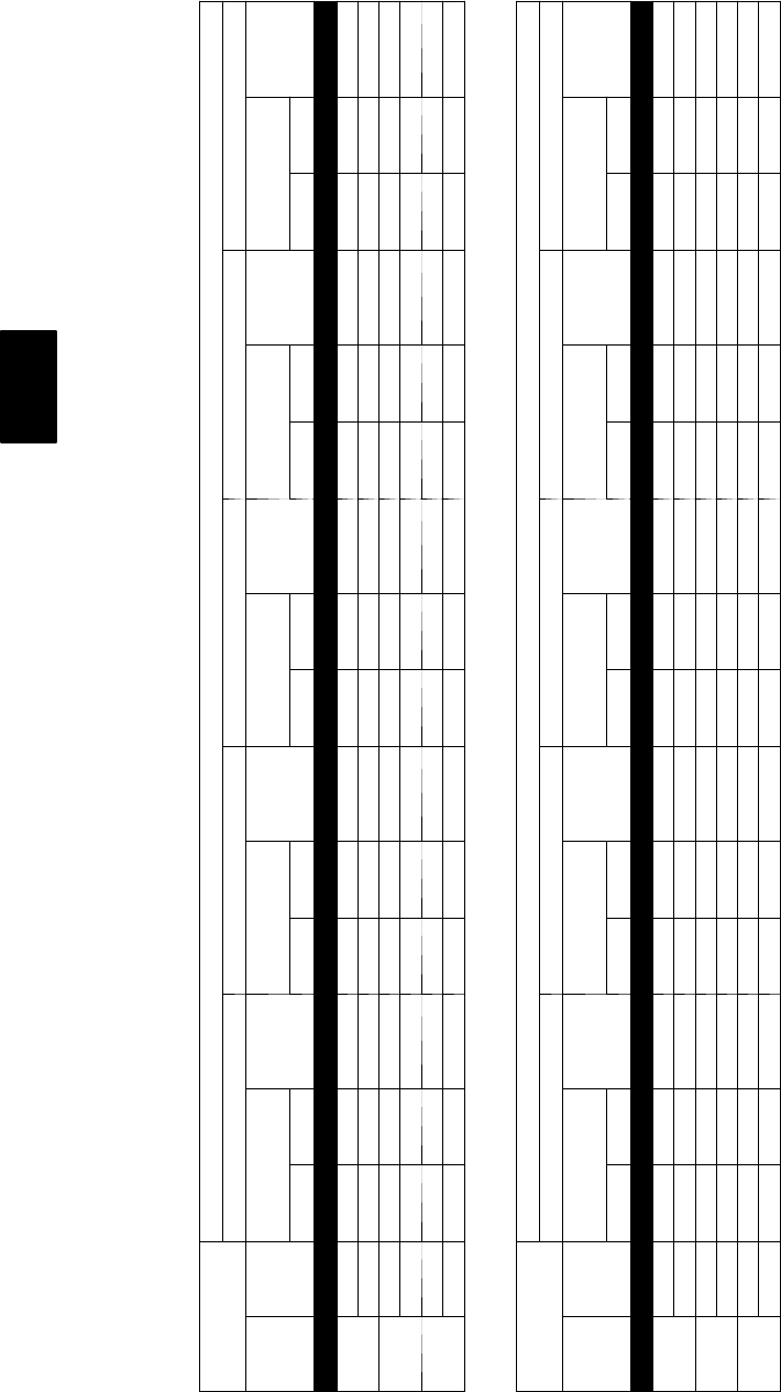
28
PERFORMANCE DATA--STANDARD ECM INDOOR MOTOR
Heating Capacity
50XT060 Low
INDOOR AIR OUTDOOR COIL ENTERING AIR TEMPERATURES _F(_C)
--10 (--23.3) 0 (--17.7) 10 (--12.2) 17 (--8.3) 20 (--6.6)
EDB
_F
(_C)
CFM
Capacity
MBtuh
Total
System
KW
Capacity
MBtuh
Total
System
KW
Capacity
MBtuh
Total
System
KW
Capacity
MBtuh
Total
System
KW
Capacity
MBtuh
Total
System
KW
Total Integ Total Integ Total Integ Total Integ Total Integ
60
(15.6)
1200 9.91 9.11 2.55 13.43 12.36 2.64 17.58 16.14 2.72 20.92 19.07 2.78 22.45 20.36 2.81
1370 10.02 9.22 2.55 13.56 12.48 2.62 17.73 16.28 2.69 21.10 19.23 2.74 22.64 20.54 2.76
70
(21.1)
1200 9.46 8.70 2.89 12.98 11.94 2.99 17.10 15.69 3.08 20.40 18.60 3.15 21.92 19.88 3.18
1370 9.59 8.82 2.89 13.13 12.08 2.97 17.29 15.87 3.05 20.61 18.79 3.10 22.14 20.08 3.13
80
(26.7)
1200 8.82 8.11 3.25 12.35 11.36 3.36 16.47 15.12 3.46 19.75 18.01 3.54 21.27 19.29 3.57
1370 8.96 8.24 3.25 12.52 11.52 3.34 16.67 15.30 3.43 19.98 18.22 3.49 21.51 19.51 3.52
50XT060 Low Con’t.
INDOOR AIR OUTDOOR COIL ENTERING AIR TEMPERATURES _F(_C)
30 (--1.1) 40 (4.4) 47 (8.3) 50 (10) 60 (15.5)
EDB
_F
(_C)
CFM
Capacity
MBtuh
Total
System
KW
Capacity
MBtuh
Total
System
KW
Capacity
MBtuh
Total
System
KW
Capacity
MBtuh
Total
System
KW
Capacity
MBtuh
Total
System
KW
Total Integ Total Integ Total Integ Total Integ Total Integ
60
(15.6)
1200 28.14 24.66 2.91 35.04 35.04 3.03 40.62 40.62 3.13 43.31 43.31 3.18 53.58 53.58 3.38
1370 28.41 24.90 2.84 35.43 35.43 2.94 41.18 41.18 3.03 43.95 43.95 3.07 54.06 54.06 3.19
70
(21.1)
1200 27.54 24.13 3.28 34.06 34.06 3.40 39.50 39.50 3.51 42.04 42.04 3.56 51.83 51.83 3.77
1370 27.81 24.37 3.21 34.46 34.46 3.31 40.01 40.01 3.40 42.63 42.63 3.44 52.74 52.74 3.62
80
(26.7)
1200 26.82 23.50 3.69 33.24 33.24 3.82 38.34 38.34 3.92 40.91 40.91 3.99 50.19 50.19 4.21
1370 27.11 23.76 3.61 33.60 33.60 3.71 38.85 38.85 3.80 41.41 41.41 3.85 51.04 51.04 4.04
LEGEND
Cap. — Heating Capacity (1000 Btuh) (Includes Indoor--Fan Motor Heat)
db —DryBulb
kW — Total Power Input (Includes Compressor Motor Power Input Outdoor--Fan Motor Input, and Indoor--Fan Motor Input)
rh — Relative Humidity
NOTES:
Integrated capacity is maximum (instantaneous) capacity less the effect of frost on the outdoor coil and the heat required to defrost it.
50XT
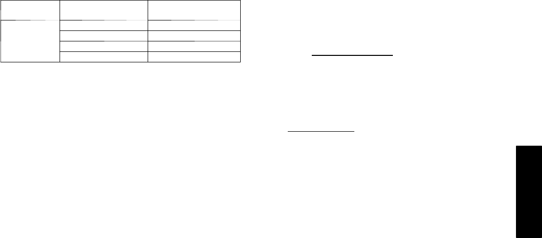
29
PERFORMANCE DATA (CONT)
Multiplication Factors
Heater kW
Rating
Voltage Distribution
V/3/60 Multiplication Factor
240
200 .69
208 .75
230 .92
240 1.00
LEGEND
BF— Bypass Factor
edb— Entering Dry--Bulb
Ewb— Entering Wet--Bulb
kW — Total Unit Power Input
ldb— Leaving Dry--Bulb
lwb— Leaving Wet--Bulb
SHC— Sensible Heat Capacity (1000 Btuh)
TC — Total Capacity (1000 Btuh) (net)
*At 75°F (23.8°C) entering dry bulb (Tennessee Valley Authority
[TVA] rating conditions); all other at 80°F (26.6°C) entering dry
bulb.
COOLING NOTES:
1. Ratings are net; they account for the effects of the evaporator
fan motor power and heat.
2. Direct interpolation is permissible. Do not extrapolate.
3. The following formulas may be used:
Example: 15.0 kW (at 240v) heater on 208v
= 15.0 (.75 mult factor)
= 11.25 capacity at 208v
Sensible capacity (Btuh)
1.10 x cfm
tldb = tedb --
Wet --- bulb temperature corresponding to enthalpy
air leaving evaporator coil (hlwb)
tlwb =
total capacity (Btuh)
4.5 x cfm
hlwb = he w b ---
Where: hewb = Enthalpy of air entering evaporator coil
4. The SHC is based on 80_F (26.6_C) edb temperature of air
entering evaporator coil. Below 80_F (26.6_C) edb, subtract (corr
factor x cfm) from SHC.
Above 80_F (26.6_C) edb, add (corr factor x cfm) to SHC.
CorrectionFactor=1.10x(1+BF)x(edb+80).
5. Integrated capacity is maximum (instantaneous) capacity less the
effect of frost on the outdoor coil and the heat required to defrost it.
50XT
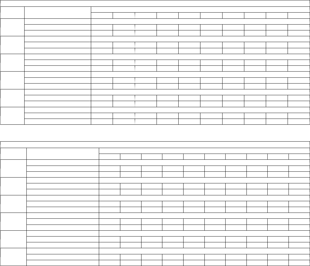
30
Wet coil air delivery -- low stage
208/230 VOLT
UNIT
SIZE SYSTEM SETTING EXTERNAL STATIC PRESSURE (in. wc)
0.1 0.2 0.3 0.4 0.5 0.6 0.7 0.8 0.9 1.0
024
COMFORT (Default) Variable based on Comfort Settings
EFFICIENCY 525 525 525 525 525 525 525 525 525 525
MAX 600 600 600 600 600 600 600 600 600 600
030
COMFORT (Default) Variable based on Comfort Settings
EFFICIENCY 613 613 613 613 613 613 613 613 613 613
MAX 700 700 700 700 700 700 700 700 700 700
036
COMFORT (Default) Variable based on Comfort Settings
EFFICIENCY 743 743 743 743 743 743 743 743 743 743
MAX 850 850 850 850 850 850 850 850 850 850
042
COMFORT (Default) Variable based on Comfort Settings
EFFICIENCY 853 853 853 853 853 853 853 853 853 853
MAX 975 975 975 975 975 975 975 975 975 975
048
COMFORT (Default) Variable based on Comfort Settings
EFFICIENCY 963 963 963 963 963 963 963 963 963 963
MAX 1100 1100 1100 1100 1100 1100 1100 1100 1100 1100
060
COMFORT (Default) Variable based on Comfort Settings
EFFICIENCY 1200 1200 1200 1200 1200 1200 1200 1200 1200 1200
MAX 1372 1372 1372 1372 1372 1372 1372 1372 1372 1372
Wet coil air delivery -- high stage
208/230 VOLT
UNIT
SIZE SYSTEM SETTING EXTERNAL STATIC PRESSURE (in. wc)
0.1 0.2 0.3 0.4 0.5 0.6 0.7 0.8 0.9 1.0
024
COMFORT (Default) Variable based on Comfort Settings
EFFICIENCY 700 700 700 700 700 700 700 700 700 700
MAX 800 800 800 800 800 800 800 800 800 800
030
COMFORT (Default) Variable based on Comfort Settings
EFFICIENCY 875 875 875 875 875 875 875 875 875 875
MAX 1000 1000 1000 1000 1000 1000 1000 1000 1000 1000
036
COMFORT (Default) Variable based on Comfort Settings
EFFICIENCY 1050 1050 1050 1050 1050 1050 1050 1050 1050 1050
MAX 1200 1200 1200 1200 1200 1200 1200 1200 1200 1200
042
COMFORT (Default) Variable based on Comfort Settings
EFFICIENCY 1225 1225 1225 1225 1225 1225 1225 1225 1225 1225
MAX 1400 1400 1400 1400 1400 1400 1400 1400 1400 1400
048
COMFORT (Default) Variable based on Comfort Settings
EFFICIENCY 1400 1400 1400 1400 1400 1400 1400 1400 1400 1400
MAX 1600 1600 1600 1600 1600 1600 1600 1600 1600 1600
060
COMFORT (Default) Variable based on Comfort Settings
EFFICIENCY 1750 1750 1750 1750 1750 1750 1750 1750 1750 1750
MAX 2000 2000 2000 2000 2000 2000 2000 2000 2000 2000
Air delivery values are based on operating voltage of 230v, and wet coil. Filter and electric heater will not change air delivery values.
NOTES:
1. See User Interface instructions for more information on Max, Efficiency, and Comfort Settings
2. Efficiency Setting operates at 350 cfm/ton (nominal) and Max Setting operates at 400 cfm/ton (nominal)
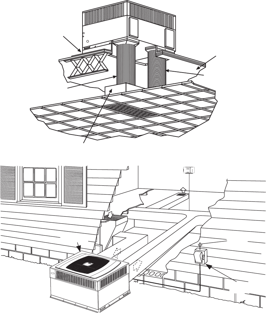
31
TYPICAL PIPING AND WIRING
ROOF
RETURN-AIR
FLEXIBLE DUCT
CEILING
CONCENTRIC DIFFUSER BOX
(FIELD-SUPPLIED)
SUPPLY-AIR
FLEXIBLE DUCT
ROOF-MOUNTING
CURB
C00023
USER
INTERFACE
DISCONNECT
PER NEC*
FROM
POWER
SOURCE
RETURN
AIR
TOP COVER
*NEC - NATIONAL ELECTRICAL CODE
A06279
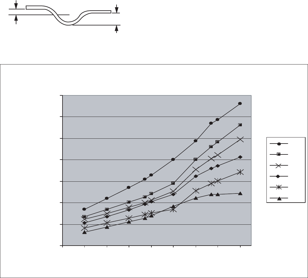
32
APPLICATION DATA
Condensate trap — A 2--in. (51 mm) condensate trap must be field
supplied.
1” (25mm) MIN.
2” (50mm) MIN.
TRAP
OUTLET
Ductwork — Secure downflow discharge ductwork to roof curb. For
horizontal discharge applications, attach ductwork to unit with
flanges.
To convert a unit to downflow discharge — Units are equipped
with factory--installed inserts in the downflow openings. Remove the
inserts similar to removing an electrical knock--out. Leave on duct
covers to seal the horizontal discharge openings in the unit. Units
installed in horizontal discharge orientation do not require duct cov-
ers.
Minimum cooling ambient operating temperature —Allstan-
dard units have a minimum ambient operating temperature of 55°F
(12.7°C). With low--ambient cooling enabled at the UI, units can op-
erate at temperatures down to 0°F (--17.7°C).
Maximum operating outdoor air temperature — Maximum out-
door operating air temperature for cooling is 125°F (51.6°C).
Balance Point Worksheet
0
10
20
30
40
50
60
70
-20 -10 0 10 20 30 40 50 60
Outdoor Air Temp (Deg F)
Building Heat Loss, 1000BTUH
Unit Integrated Heating Capacity,
1000BTUH
060
048
042
036
030
024
Based on Entering Indoor Air of 70 Deg. F and Rated CFM
C03008
33
ELECTRICAL DATA
UNIT SIZE V--PH--HZ
VOLTAGE
RANGE COMPRESSOR OFM
FLA
IFM
FLA
ELECTRIC HEAT SINGLE POINT POWER
SUPPLY
NOMINAL FLA MCA MOCP
MIN MAX RLA LRA kW*
024 208/230--1--60 187 253 15.3 52.0 0.9 4.3
-- / -- -- / -- 24.3/24.3 35/35
3.8/5.0 18.1/20.8 46.9/50.3 50/60
5.4/7.2 26.0/30.0 56.8/61.8 60/70
7.5/10.0 36.1/41.7 69.4/76.4 70/80
030 208/230--1--60 187 253 16.8 70.0 0.9 4.3
-- / -- -- / -- 26.2/26.2 40/40
3.8/5.0 18.1/20.8 48.7/52.2 50/60
5.4/7.2 26.0/30.0 58.7/63.7 60/70
7.5/10.0 36.1/41.7 71.3/78.3 80/80
11.3/15.0 54.2/62.5 93.9/104.3 100/110
036 208/230--1--60 187 253 16.7 82.0 0.9 6.8
-- / -- -- / -- 28.6/28.6 45/45
3.8/5.0 18.1/20.8 51.2/54.6 60/60
5.4/7.2 26.0/30.0 61.1/66.1 70/70
7.5/10.0 36.1/41.7 73.7/80.7 80/90
11.3/15.0 54.2/62.5 96.3/106.7 100/110
042 208/230--1--60 187 253 21.8 96.0 0.9 6.8
-- / -- -- / -- 34.9/34.9 50/50
3.8/5.0 18.1/20.8 57.5/60.9 60/70
5.4/7.2 26.0/30.0 67.4/72.4 70/80
7.5/10.0 36.1/41.7 80.0/87.0 90/90
11.3/15.0 54.2/62.5 102.6/113.0 110/125
15.0/20.0 72.2/83.3 125.2/139.1 150/150
048 208/230--1--60 187 253 27.8 96.0 1.5 6.8
-- / -- -- / -- 43.1/43.1 60/60
3.8/5.0 18.1/20.8 65.7/69.1 70/70
5.4/7.2 26.0/30.0 75.6/80.6 80/90
7.5/10.0 36.1/41.7 88.2/95.2 90/100
11.3/15.0 54.2/62.5 110.8/121.2 125/125
15.0/20.0 72.2/83.3 133.4/147.3 150/150
060 208/230--1--60 187 253 27.3 118.0 1.9 9.1
-- / -- -- / -- 45.2/45.2 60/60
3.8/5.0 18.1/20.8 67.7/71.2 70/80
5.4/7.2 26.0/30.0 77.6/82.7 80/90
7.5/10.0 36.1/41.7 90.3/97.2 100/110
11.3/15.0 54.2/62.5 112.9/123.3 125/125
15.0/20.0 72.2/83.3 135.4/149.3 150/150
*Heater capacity (kW) based on heater voltage of 208v & 240v. If power distribution voltage to unit varies from rated heater voltage, heater kW will vary accord-
ingly.
LEGEND
FLA — Full Load Amps
LRA — Locked Rotor Amps
MCA — Minimum Circuit Amps
MOCP — Maximum Overcurrent Protection
RLA — Rated Load Amps
NOTES:
1. In compliance with NEC (National Electrical Code) requirements
for multimotor and combination load equipment (refer to NEC
Articles 430 and 440), the overcurrent protective device for the
unit shall be Power Supply fuse. The CGA (Canadian Gas
Association) units may be fuse or circuit breaker.
2. Minimum wire size is based on 60 C copper wire. If other than
60 C wire is used, or if length exceeds wire length in table,
determine size from NEC.
®
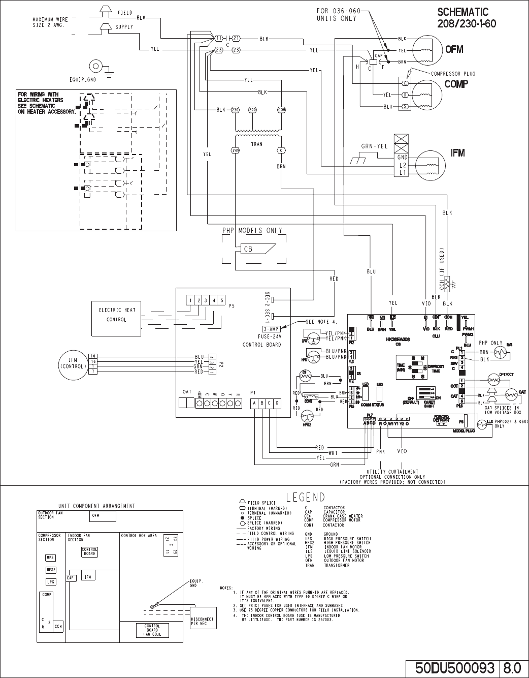
34
TYPICAL WIRING SCHEMATIC — 230--1--60
A08201
35
CONTROLS
Sequence of Operation
The 50XT packaged heat pump is designed for installation with a
communicating UI. Thisunit will not respond to commandsprovided
by a common thermostat except under certain emergency situations.
The UI uses temperature, humidity and other data supplied from
indoor and outdoor system components to control heating or cooling
system for optimum comfort. The unit will be commanded by the UI
to supply airflow. The unit will operate the indoor fan at requested
airflow for most modes.
The nominal requested airflow in high stage will be 350 cfm per ton
of nominal cooling capacity as defined by unit size. Actual airflow
request will be adjusted from nominal using indoor and outdoor
temperature and indoor humidity data to optimize the system
operation for occupant comfort and system efficiency. Refer to UI
literature for further system control details.
Airflow during electric heater operation must be greater than a
minimum level for safe operation. If UI instructs unit to turn on
electric heat and the requested airflow is less than the minimum level
the fan coil control will override requested value.
NOTE: Once the compressor has started and then has stopped, it
should not be started again until 4 minutes have elapsed. The cooling
cycle remains “on” until the room temperature drops to point that is
slightly below the cooling control setting of the UI.
COOLING AND HEATING OPERATION
With a call for first stage cooling, the outdoor fan, reversing valve,
and low stage compressor are energized. If low--stage cannot
satisfy cooling demand, high--stage cooling is energized by the UI.
After second stage is satisfied, the unit returns to low--stage
operation until first stage is satisfied or until second stage is
required again. When both first stage and second stage cooling are
satisfied, the compressor will shut off. The reversing valve will
remain energized until the control board power is removed or a call
for heating is initiated. With a call for heating, the outdoor fan and
compressor are energized. The compressor will operate in high or
low stage operation, as needed, to meet the heating demand. When
the heating demand is satisfied, the compressor and fan will shut
off. The reversing valve is de--energized in the heating mode.
NOTE: When two--stage unit is operating at low--stage, system
vapor (suction) pressure will be higher than a standard single--stage
system or high--stage operation.
NOTE: Outdoor fan motor will continue to operate for one
minute after compressor shuts off, when outdoor ambient is greater
than or equal to 100°F(38°C).
UTILITY INTERFACE WITH INFINITY CONTROL
The utility curtailment relay should be connected to factory
supplied pigtails (PINK connected to R, VIOLET connected to Y2
on the control board) located in the low voltage splice box (see
Typical Wiring Schematic ). This input allows a power utility
device to interrupt compressor operation during peak load periods.
When the utility sends a signal to shut the system down, the UI will
display “Curtailment Active”.
Infinity Controlled Low Ambient Cooling
NOTE: When this unit is operating below 55_F (12.7°C) outdoor
temperature, provisions must be made for low ambient operation.
This unit is capable of low ambient cooling down to 0_F
(--17.7°C)ONLY when using the Infinity control. A low ambient kit
isnotrequired, and the outdoorfan motor doesnot need to be replaced
for Infinity controlled low ambient operation. Low ambient cooling
must be enabled in the UI set--up. Fan may not begin to cycle until
about 40_F(4.4°C) OAT. Fan will cycle based on coil and outdoor
air temperature.
36
GUIDE SPECIFICATIONS
SINGLE--PACKAGED HEAT PUMP UNITS
CONSTANT VOLUME APPLICATION
HVAC GUIDE SPECIFICATIONS
SIZE RANGE: 2 TO 5 TONS, NOMINAL (COOLING)
MODEL NUMBER: 50XT
PART I -- GENERAL
SYSTEM DESCRIPTION
Outdoor rooftop or ground mounted heat pump unit utilizing a
hermetic, 2--stage scroll compressor for heating and cooling duty
and optional electric heating. Unit shall discharge supply air ver-
tically or horizontally as shown on contract drawings. Outdoor
fan/coil section shall have a draw--thru design with vertical dis-
charge for minimum sound levels.
QUALITY ASSURANCE
A. Unit shall be rated in accordance with ARI Standards
210/240 and 270.
B. Unit shall be designed in accordance with UL Standard
1995.
C. Unit shall be manufactured in a facility registered to ISO
9001 manufacturing quality standard
D. Unit shall be UL listed and c--UL certified as a total
package for safety requirements.
E. Roof curb shall be designed to conform to NRCA
Standards.
F. Insulation and adhesives shall meet NFPA 90A
requirements for flame spread and smoke generation.
G. Cabinet insulation shall meet ASHRAE Standard 62P.
DELIVERY, STORAGE, AND HANDLING
Unit shall be stored and handled per manufacturer’s recommen-
dations.
PART 2-- PRODUCTS
EQUIPMENT
A. General:
Factory--assembled, single--piece, heat pump. Contained within
the unit enclosure shall be all factory wiring, piping, controls, re-
frigerant charge (R--410A), and special features required prior to
field start--up.
B. Unit Cabinet:
1. Unit cabinet shall be constructed of phosphated, zinc--coated,
prepainted steel capable of withstanding 500 hrs of salt spray.
2. Normal service shall be through a single removable cabinet
panel.
3. The unit shall be constructed on a rust proof unit base that has
an externally trapped, integrated sloped drain pan.
4. Indoor fan compartment top surface shall be insulated with a
minimum 1/2--in. (13 mm) thick, flexible fiberglass
insulation, coated on the air side and retained by adhesive and
mechanical means. The indoor wall sections will be insulated
with a foil--faced insulation capable of being wiped clean.
Aluminum foil--faced fiberglass insulation shall be used in the
entire indoor air cavity section.
5. Unit shall have a field--supplied condensate trap.
C. Fans:
1. The indoor fan shall be variable--speed motor and control, as
shown on equipment drawings.
2. Fan wheel shall be made from steel, be double--inlet type. It
shall have forward--curved blades with a corrosion--resistant
finish and shall be dynamically balanced.
3. Outdoor fan shall be of the direct--driven propeller type with
aluminum blades, riveted to corrosion--resistant steel spiders.
It shall be dynamically balanced, and discharge air vertically.
D. Compressor:
1. Fully hermetic, 2--stage scroll compressors with
factory--installed vibration isolation.
2. Scroll compressors shall be standard on all units.
3. Compressor Protection:
Defrost control shall protect compressor by preventing
“short cycling.”
E. Coils:
1. Indoor and outdoor coils shall have aluminum plate fins
mechanically bonded to seamless copper tubes with all joints
brazed.
2. Tube sheet openings shall be bellied to prevent tube wear.
F. Refrigerant Metering Device:
Refrigerant metering device shall be of the single body,
fixed orifice feed type (outdoor) and TXV (indoor).
G. Filters:
Filter section shall consist of field--installed, throw--away,
1--in. thick fiberglass filters of commercially available sizes.
H. Controls and Safeties:
1. Unit controls shall be complete with self--contained low
voltage control circuit.
2. Units shall incorporate an internal compressor protector that
provides reset capability.
3. Unit shall provide high-- and low--/loss--of--charge pressure
safety protection.
I. Operating Characteristics:
1. Unit shall be capable of starting and running at 125°F
(51.6_C) ambient outdoor temperature, exceeding maximum
load criteria of ARI Standard 240.
2. Compressor shall be capable of operation down to 55°F
(12.7_C) ambient outdoor temperature in cooling and --10°F
in heating.
3. Unit shall be capable of low--ambient cooling (below 55_F
(12.7_C) ambient outdoor temperature) with low--ambient
cooling enabled on the UI.
J. Electrical Requirements:
All unit power wiring shall enter unit cabinet at a single location.
K. Motors:
1. Compressor motors shall be of the refrigerant--cooled type
with line--break thermal and current overload protection.
2. All fan motors shall have permanently lubricated bearings and
inherent automatic--reset thermal overload protection.
3. Outdoor fan motor shall be totally enclosed.
L. Grille
1. Louvered Grille:
Louvered grille shall be standard on all units.
37
GUIDE SPECIFICATIONS (CONT)
M. Special Features:
1. Coil Options:
Shall include factory--installed optional tin--plated indoor
copper/copper and vinyl--coated refrigerant coils.
2. Flat Roof Curb:
Curbs shall have seal strip and a wood nailer for flashing and
shall be installed per manufacturer’s instructions.
3. Manual Outdoor Air Damper:
Package shall consist of damper, bird screen, and rain hood
which can be preset to admit outdoor air for year--round ven-
tilation.
4. InfinitytUser Interface:
To providefortwo--stage heat pump heating, two--stage cool-
ing, and electric (auxiliary) heat, in addition to manual or au-
tomatic changeover and indoor fan control.
5. Low--Ambient Cooling:
Low--ambient cooling must be enabled in the UI setup to al-
low unit to operate down to 0°F(--17_C) outdoor ambient
temperature in cooling.
6. Filter Rack Kit:
Shall provide filter mounting for downflow and horizontal
applications.
7. Square--To--Round Duct Transitions:
Shall have the ability to convert the supply and return open-
ings from rectangular to round (024--048 sizes only).
8. Crankcase Heater:
Shall provide anti--floodback protection for low--load cool-
ing applications. (Standard on 042--060 sizes.)
9. Electric heaters:
a. Electric heater shall be available as a field--installed
option.
b. Heater elements shall be open--wire type, adequately
supported and insulated with ceramic bushings.
c. Electric heater packages must provide single--point
power connection capability.
10. Compressor Hard Start Kit:
Shall be available to give a boost to the compressor motor at
each start--up.

38
Copyright 2008 Carrier Corp. D7310 W. Morris St. DIndianapolis, IN 46231 Printed in U.S.A. Edition Date: 06/08
Manufacturer reserves the right to change, at any time, specifications and designs without notice and without obligations.
Catalog No: 50XT---04PD
Replaces: 50XT---3PD
