Carrier Refrigerator Ph61 Users Manual OpCvr
PH61 to the manual 89ee1a1a-7316-47f4-8c73-4c09f3a64dda
2015-01-24
: Carrier Carrier-Refrigerator-Ph61-Users-Manual-311019 carrier-refrigerator-ph61-users-manual-311019 carrier pdf
Open the PDF directly: View PDF ![]() .
.
Page Count: 78

Model PH61
Heat Treatment
Shake Freezer
Operating Instructions
048119-M 7/31/07

Complete this page for quick reference when service is required:
Taylor Distributor:
Address:
Phone:
Fax:
E-mail:
Service:
Parts:
Date of Installation:
Information found on the data label:
Model Number:
Serial Number:
Electrical Specs: Voltage Cycle
Phase
Maximum Fuse Size: A
Minimum Wire Ampacity: A
E
A
ugust, 2007 Taylo
r
All rights reserved.
048119-M
The word Taylor and the Crown design
are registered trademarks in the United States
of America and certain other countries.
Taylor Company
a division of Carrier Commercial Refrigeration, Inc.
750 N. Blackhawk Blvd.
Rockton, IL 61072

Model PH61 Table of Contents
Table of Contents
Section 1 To the Installer 1............................................
Installer Safety 1........................................................
Site Preparation 1.......................................................
Air Cooled Units 1.......................................................
Water Connections (Water Cooled Units Only) 2............................
Electrical Connections 2.................................................
Beater Rotation 3.......................................................
Refrigerant 3...........................................................
Section 2 To the Operator 4...........................................
Compressor Warranty Disclaimer 5.......................................
Section 3 Safety 6....................................................
Section 4 Operator Parts Identification 8...............................
PH61 Exploded View 8..................................................
Beater and Door Assembly 10.............................................
X57028-14 Pump A. - Mix Simplified 12....................................
Accessories 13..........................................................
X44127 Brush A.-Package-HT 14.........................................
Syrup Tank 15...........................................................
Section 5 Important: To the Operator 16.................................
Symbol Definitions 16....................................................
Power Switch 17.........................................................
Liquid Crystal Display 17..................................................
Indicator Lights 17.......................................................
Reset Mechanism 17.....................................................
Operating Screen Descriptions 18..........................................
Operator Menu 21.......................................................

Table of Contents Model PH61
Table of Contents - Page 2
Section 6 Operating Procedures 25.....................................
Equipment Set Up 25.....................................................
Daily Closing Procedures 36..............................................
Daily Opening Procedures 39..............................................
Syrup System 41.........................................................
Closing Procedures 45...................................................
Draining Product From the Freezing Cylinder 45.............................
Brush Cleaning 48.......................................................
Sanitizing the Syrup Systems 49...........................................
Section 7 Important: Operator Checklist 51..............................
During Cleaning and Sanitizing 51.........................................
Troubleshooting Bacterial Count: 51........................................
Regular Maintenance Checks: 51..........................................
Winter Storage 52........................................................
Section 8 Troubleshooting Guide 53....................................
Section 9 Parts Replacement Schedule 59...............................
Section 10 Parts List 60.................................................
Wiring Diagrams 73......................................................
Note: Continuing research results in steady improvements; therefore, information
in this manual is subject to change without notice.
EAugust, 2007 Taylor
All rights reserved.
048119-M
The word Taylor and the Crown design
are registered trademarks in the United States
of America and certain other countries.
Taylor Company
a division of Carrier Commercial Refrigeration, Inc.
750 N. Blackhawk Blvd.
Rockton, IL 61072

1
Model PH61 To the Installer
081208
Section 1 To the Installer
The following are general installation instructions.
For complete installation details, please see the
check out card.
Installer Safety
In all areas of the world, equipment should
be installed in accordance with existing local codes.
Please contact your local authorities if you have any
questions.
Care should be taken to ensure that all basic safety
practices are followed during the installation and
servicing activities related to the installation and
service of Taylor equipment.
SOnly authorized Taylor service personnel
should perform installation and repairs on
the equipment.
SAuthorized service personnel should consult
OSHA Standard 29CFRI910.147 or the
applicable code of the local area for the
industry standards on lockout/tagout
procedures before beginning any installation
or repairs.
SAuthorized service personnel must ensure
that the proper PPE is available and worn
when required during installation and
service.
SAuthorized service personnel must remove
all metal jewelry, rings, and watches before
working on electrical equipment.
The main power supply(s) to the freezer
must be disconnected prior to performing any
repairs. Failure to follow this instruction may result in
personal injury or death from electrical shock or
hazardous moving parts as well as poor
performance or damage to the equipment.
Note:Allrepairsmustbeperformedbyan
authorized Taylor Service Technician.
This unit has many sharp edges that can
cause severe injuries.
Site Preparation
Review the area the unit is to be installed in before
uncrating the unit making sure that all possible
hazards the user or equipment may come into have
been addressed.
Air Cooled Units
Air cooled units require a minimum of 6” (152 mm)
of clearance around all sides of the freezer. Failure
to allow adequate clearance can reduce the
refrigeration capacity of the freezer and possibly
cause permanent damage to the compressors.
For Indoor Use Only: This unit is designed to
operate indoors, under normal ambient
temperatures of 70_-75_F(21_-24_C). The freezer
has successfully performed in high ambient
temperatures of 104_(40_C) at reduced capacities.
This unit must NOT beinstalledinanarea
where a water jet or hose can be used. NEVER use
a water jet or hose to rinse or clean the unit. Failure
to follow this instruction may result in electrocution.
This unit must be installed on a level surface
to avoid the hazard of tipping. Extreme care should
be taken in moving this equipment for any reason.
Two or more persons are required to safely move
this unit. Failure to comply may result in personal
injury or equipment damage.
Uncrate the unit and inspect it for damage. Report
any damage to your Taylor Distributor.
This piece of equipment is made in the USA and has
USA sizes of hardware. All metric conversions are
approximate and vary in size.
2 Model PH61To the Installer
080910
Water Connections
(Water Cooled Units Only)
An adequate cold water supply must be provided
with a hand shut-off valve. On the rear of the unit,
two 3/8” I.P.S. water connections for inlet and outlet
have been provided for easy hook-up. 1/2” inside
diameter water lines should be connected to the
machine. (Flexible lines are recommended, if local
codes permit.) Depending on local water conditions,
it may be advisable to install a water strainer to
prevent foreign substances from clogging the
automatic water valve. There will be only one water
“in” and one water “out” connection. DO NOT install
a hand shut-off valve on the water “out” line! Water
should always flow in this order: first, through the
automatic water valve; second, through the
condenser; and third, through the outlet fitting to an
opentrapdrain.
A back flow prevention device is
required on the incoming water connection side.
Please refer to the applicable National, State, and
local codes for determining the proper configuration.
Electrical Connections
In the United States, this equipment is intended to
be installed in accordance with the National
Electrical Code (NEC), ANSI/NFPA 70-1987. The
purpose of the NEC code is the practical
safeguarding of persons and property from hazards
arising from the use of electricity. This code contains
provisions considered necessary for safety.
Compliance therewith and proper maintenance will
result in an installation essentially free from hazard!
In all other areas of the world, equipment should be
installed in accordance with the existing local codes.
Please contact your local authorities.
FOLLOW YOUR LOCAL ELECTRICAL CODES!
Each freezer requires one power supply. Check the
data label on the freezer for fuse, circuit ampacity
and electrical specifications. Refer to the wiring
diagram provided inside of the electrical box, for
proper power connections.
CAUTION: THIS EQUIPMENT MUST BE
PROPERLY GROUNDED! FAILURE TO DO SO
CAN RESULT IN SEVERE PERSONAL INJURY
FROM ELECTRICAL SHOCK!
This unit is provided with an equipotential
grounding lug that is to be properly attached to the
rear of the frame by the authorized installer. The
installation location is marked by the equipotential
bonding symbol (5021 of IEC 60417-1) on both the
removable panel and the equipments frame.
SStationary appliances which are not
equipped with a power cord and a plug or
another device to disconnect the appliance
from the power source must have an all-pole
disconnecting device with a contact gap of
at least 3mm installed in the external
installation.
SAppliances that are permanently connected
to fixed wiring and for which leakage
currents may exceed 10 mA, particularly
when disconnected or not used for long
periods, or during initial installation, shall
have protective devices such as a GFI, to
protect against the leakage of current,
installed by the authorized personnel to the
local codes.
SSupply cords used with this unit shall be
oil-resistant, sheathed flexible cable not
lighter than ordinary polychloroprene or
other equivalent synthetic
elastomer-sheathed cord (Code designation
60245 IEC 57) installed with the proper cord
anchorage to relieve conductors from strain,
including twisting, at the terminals and
protect the insulation of the conductors from
abrasion.

3
Model PH61 To the Installer
080910
Beater Rotation
Beater rotation must be clockwise as viewed
looking into the freezing cylinder.
Note: The following procedures should be
performed by a trained service technician.
To correct rotation on a three-phase unit,
interchange any two incoming power supply lines at
freezer main terminal block only.
To correct rotation on a single-phase unit, change
the leads inside the beater motor. (Follow diagram
printed on motor.)
Electrical connections are made directly to the
terminal block. The terminal block is provided in the
main control box located behind the rear panel.
Refrigerant
In consideration of our environment, Taylor
proudly uses only earth friendly HFC refrigerants.
The HFC refrigerant used in this unit is R404A. This
refrigerant is generally considered non-toxic and
non-flammable, with an Ozone Depleting Potential
(ODP) of zero (0).
However, any gas under pressure is potentially
hazardous and must be handled with caution.
NEVER fill any refrigerant cylinder completely with
liquid. Filling the cylinder to approximately 80% will
allow for normal expansion.
Refrigerant liquid sprayed onto the skin may
cause serious damage to tissue. Keep eyes and skin
protected. If refrigerant burns should occur, flush
immediately with cold water. If burns are severe,
apply ice packs and contact a physician
immediately.
Taylor reminds technicians to be cautious of
government laws regarding refrigerant recovery,
recycling, and reclaiming systems. If you have any
questions regarding these laws, please contact the
factory Service Department.
WARNING: R404A refrigerant used in
conjunction with polyolester oils is extremely
moisture absorbent. When opening a refrigeration
system, the maximum time the system is open must
not exceed 15 minutes. Cap all open tubing to
prevent humid air or water from being absorbed by
the oil.
4 Model PH61To the Operator
080910
Section 2 To the Operator
The freezer you have purchased has been carefully
engineered and manufactured to give you
dependable operation. When properly operated and
cared for, it will produce a consistent quality product.
Like all mechanical products, this machine will
require cleaning and maintenance. A minimum
amount of care and attention is necessary if the
operating procedures outlined in this manual are
followed closely.
This Operator's Manual should be read before
operating or performing any maintenance on your
equipment.
The Model PH61 will NOT eventually compensate
and correct for any errors during the set-up or filling
operations. Thus, the initial assembly and priming
procedures are of extreme importance. It is strongly
recommended that personnel responsible for the
equipment's operation, both assembly and
disassembly, study these procedures in order to be
properly trained.
In the event you should require technical assistance,
please contact your local authorized Taylor
Distributor.
Note: Warranty is valid only if the parts are
authorized Taylor parts, purchased from an
authorized Taylor Distributor, and the required
service work is provided by an authorized Taylor
service technician. Taylor reserves the right to deny
warranty claims on equipment or parts if
non-approved parts or refrigerant were installed in
the machine, system modifications were performed
beyond factory recommendations, or it is determined
that the failure was caused by neglect or abuse.
Note: Constant research results in steady
improvements; therefore, information in this
manual is subject to change without notice.
When your machine is delivered or if it has been in
the OFF position for more than 24 hours,
disassemble the freezer following procedures found
on page 47.Follow assembly procedures on
page 25 to re-assemble your machine.
Dairy products are susceptible to
bacterial contamination due to improper product
handling. Therefore, be sure to use clean
sanitary conditions when handling mix.
The machine must be disassembled, cleaned,
sanitized, and lubricated every two weeks.
ALWAYS FOLLOW LOCAL HEALTH CODES.
During the heat treatment process, the product is
brought to a temperature sufficient to destroy
bacteria and is returned to a standby temperature.
The special control system will insure that the
product is heated and maintained at the set
temperature for the full 30 minutes. This time is
required to insure that bacteria is destroyed. If the
freezer was unable to complete the heating cycle,
the LCD will read:
“HEAT TREAT CYCLE FAILURE - FREEZER
LOCKED - PRESS SEL KEY”. If this is the case, or
if you require technical assistance, please contact
your local authorized Taylor Distributor.
If the crossed out wheeled bin symbol is
affixed to this product, it signifies that this product is
compliant with the EU Directive as well as other
similar legislation in effect after August 13, 2005.
Therefore, it must be collected separately after its
use is completed, and cannot be disposed as
unsorted municipal waste.
The user is responsible for returning the product to
the appropriate collection facility, as specified by
your local code.
For additional information regarding applicable local
laws, please contact the municipal facility and/or
local distributor.

5
Model PH61 To the Operator
Compressor Warranty Disclaimer
The refrigeration compressor(s) on this machine
are warranted for the term indicated on the
warranty card accompanying this machine.
However, due to the Montreal Protocol and the
U.S. Clean Air Act Amendments of 1990, many
new refrigerants are being tested and developed,
thus seeking their way into the service industry.
Some of these new refrigerants are being
advertised as drop-in replacements for numerous
applications. It should be noted that, in the event
of ordinary service to this machine's refrigeration
system, only the refrigerant specified on the
affixed data label should be used. The
unauthorized use of alternate refrigerants will void
your compressor warranty. It will be the owner's
responsibility to make this fact known to any
technician he employs.
It should also be noted that Taylor does not warrant
the refrigerant used in its equipment. For example, if
the refrigerant is lost during the course of ordinary
service to this machine, Taylor has no obligation to
either supply or provide its replacement either at
billable or unbillable terms. Taylor does have the
obligation to recommend a suitable replacement if
the original refrigerant is banned, obsoleted, or no
longer available during the five year warranty of the
compressor.
Taylor will continue to monitor the industry and test
new alternates as they are being developed. Should
a new alternate prove, through our testing, that it
would be accepted as a drop-in replacement, then
the above disclaimer would become null and void.
To find out the current status of an alternate
refrigerant as it relates to your compressor warranty,
call the local Taylor Distributor or the Taylor Factory.
Be prepared to provide the Model/Serial Number of
the unit in question.
6 Model PH61Safety
Section 3 Safety
We at Taylor are concerned about the safety of the
operator when he or she comes in contact with the
freezer and its parts. Taylor has gone to extreme
efforts to design and manufacture built-in safety
features to protect both you and the service
technician. As an example, warning labels have
been attached to the freezer to further point out
safety precautions to the operator.
IMPORTANT - Failure to adhere to the
following safety precautions may result in
severe personal injury or death. Failure to
comply with these warnings may damage the
machine and its components. Component
damage will result in part replacement expense
and service repair expense.
To Operate Safely:
DO NOT operate the freezer without
reading this operator's manual. Failure to follow this
instruction may result in equipment damage, poor
freezer performance, health hazards, or personal
injury.
This dispenser is provided with a grounding lug
that is to be properly attached to the rear of the frame
by the authorized installer. The installation location is
marked by the equipotential bonding symbol (5021 of
IEC 60417-1) on the removable panel and the frame.
SDO NOT operate the freezer unless it is
properly grounded.
SDO NOT operate the freezer with larger
fuses than specified on the freezer data
label.
SDO NOT attempt any repairs unless the
main power supply to the freezer has been
disconnected. Contact your local authorized
Taylor Distributor for service.
SStationary appliances which are not
equipped with a power cord and a plug or
another device to disconnect the appliance
from the power source must have an all-pole
disconnecting device with a contact gap of
at least 3mm installed in the external
installation.
SAppliances that are permanently connected
to fixed wiring and for which leakage
currents may exceed 10 mA, particularly
when disconnected or not used for long
periods, or during initial installation, shall
have protective devices such as a GFI, to
protect against the leakage of current,
installed by the authorized personnel to the
local codes.
SSupply cords used with this unit shall be
oil-resistant, sheathed flexible cable not
lighter than ordinary polychloroprene or
other equivalent synthetic
elastomer-sheathed cord (Code designation
60245 IEC 57) installed with the proper cord
anchorage to relieve conductors from strain,
including twisting, at the terminals and
protect the insulation of the conductors from
abrasion.
Failure to follow these instructions may result in
electrocution. Contact your local authorized Taylor
Distributor for service.
SDO NOT allow untrained personnel to
operate this machine.
SDO NOT operate the freezer unless all
service panels and access doors are
restrained with screws.
SDO NOT remove any internal operating
parts (example: freezer door, beater,
scraper blades, etc.) unless all control
switches are in the OFF position.
SDO NOT put objects or fingers in door spout
or spinner housing.
Failure to follow these instructions may result in
contaminated product or severe personal injury to
fingers or hands from hazardous moving parts.
7
Model PH61 Safety
080910
This unit has many sharp edges that can
cause severe injuries.
SDO NOT put objects or fingers in the door
spout. This may contaminate the product
and cause severe personal injury from blade
contact.
SUSE EXTREME CAUTION when removing
the beater asssembly. The scraper blades
are very sharp.
SCAUTION-SHARP EDGES: Two people are
required to handle the cup dispenser.
Protective gloves must be worn and the
mounting holes must NOT be used to lift or
hold the dispenser. Failure to follow this
instruction can result in personal injury to
fingers or equipment damage.
DO NOT draw product during the HEAT
cycle because of high product temperatures.
Some consumers are highly allergic to
strawberries. In some severe cases,
strawberry allergic reactions can cause
death. When serving shakes, make sure
the draw handle is closed automatically by
the portion control device and that the
white spot is visible.
WARNING!
This freezer must be placed on a level
surface. Failure to comply may result in personal
injury or equipment damage.
Cleaning and sanitizing schedules are
governed by your state or local regulatory agencies
and must be followed accordingly. Please refer to
the cleaning section of this manual for the proper
procedure to clean this unit.
DO NOT obstruct air intake and discharge openings:
6” (152 mm) minimum air space on all sides. Failure
to follow this instruction may cause poor freezer
performance and damage to the machine.
For Indoor Use Only: This unit is designed to
operate indoors, under normal ambient
temperatures of 70_-75_F(21_-24_C). The
freezer has successfully performed in high ambient
temperatures of 104_(40_C) at reduced capacities.
NOISE LEVEL: Airborne noise emission does not
exceed 78 dB(A) when measured at a distance of
1.0 meter from the surface of the machine and at a
height of 1.6 meters from the floor.
8 Model PH61Operator Parts Identification
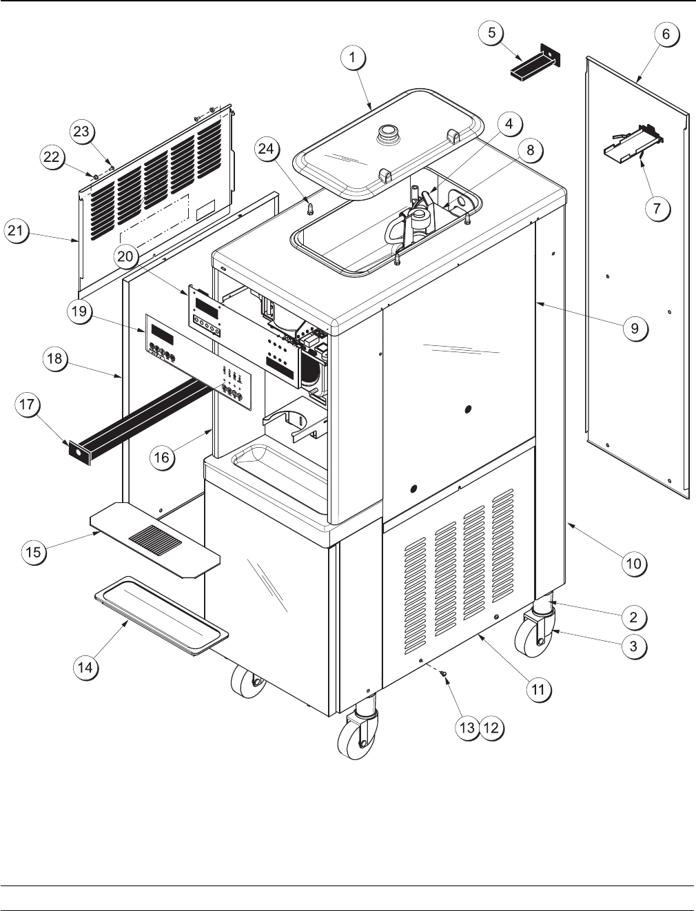
Section 4 Operator Parts Identification
PH61 Exploded
V
iew
Figure 1

9
Model PH61 Operator Parts Identification
Model PH61 Parts Identification List
ITEM DESCRIPTION PART NO.
1Kit A.-Cover-Hopper X65369
2Adaptor A.-Caster X18915
3Caster-Swivel 5/8 St. 4 in.
Wheel 018794
4Agitator A. X44797
5Pan-Drip-Rear HT 048204
6Panel-Rear 048203
7Guide A.-Drip Pan X48228
8Pump A.-Mix Simplified Shake X57028-14
9Panel-Side Upper R 056013
10 Trim-Rear Corner R 045517
*Trim-Rear Corner L 045516
11 Panel-Lower Side R 034680
12 Screw-1/4-20 x 3/8 011694
ITEM DESCRIPTION PART NO.
13 Fastener-Clip 045865
14 Tray-Drip 14-7/8 L 013690
15 Shield-Splash 022763
16 Panel A.-Front X55436
17 Pan A.-Drip X28142
*Guide A.-Drip Pan X45386
18 Panel A.-Lower Side X24397-SER
19 Decal-Dec 052280
20 Display-Liquid Crystal X38062-SER
21 Panel-Upper Side 056012
22 Washer-Plastic Pivot 013808
23 Screw-10-24 x 1/2 002077
24 Pin-Retaining- Hopper Cover 043934
*Tank-Syrup-4 Qt. 045533
*Not Shown
10 Model PH61Operator Parts Identification
091216
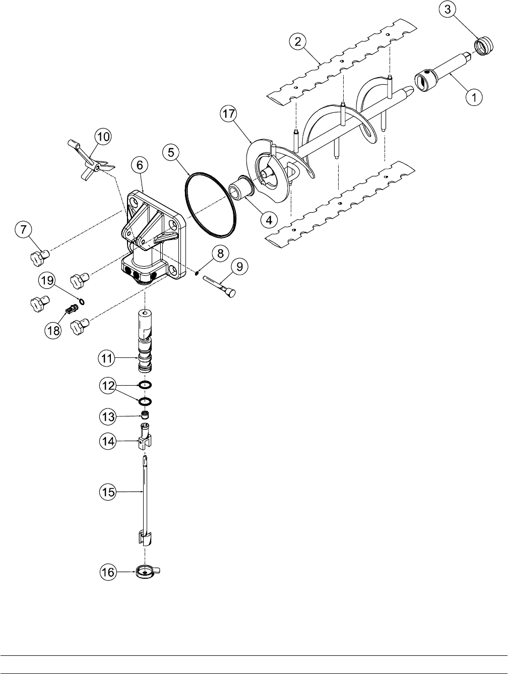
Beater and Door Assembly
Figure 2

11
Model PH61 Operator Parts Identification
081110
Beater & Door Assembly Parts Identification List
ITEM DESCRIPTION PART NO.
1SHAFT-BEATER-7 QT.
FLUTED 050985
2BLADE-SCRAPER 041103
3SEAL-DRIVE SHAFT 032560
4BEARING-FRONT 055605
5O-RING - FREEZER DOOR 033493
6DOOR A.-1 SPT-4 FLV-HT X55724-SER
7HANDSCREW (STUD NUT) 034034
8O-RING - PIVOT PIN 016272
9PIN A.-PIVOT X22820
10 HANDLE-DRAW VALVE 034003
ITEM DESCRIPTION PART NO.
11 VALVE A.-DRAW X42210
12 O-RING - DRAW VALVE 020571
13 SEAL-SPINNER SHAFT 036053
14 SPINNER-DRIVEN 034054
15 BLADE A.-SPINNER X41895
16 CAP-RESTRICTOR 033107
17 BEATER A.-SHAKE X50958
18 PLUG-SYRUP HOLE 026278
19 O-RING 024278
12 Model PH61Operator Parts Identification
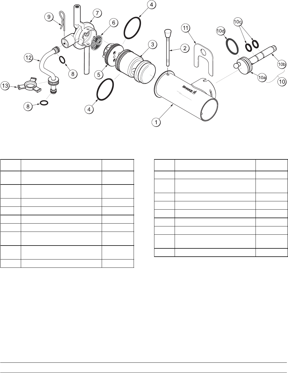
X57028-14 Pump A. - Mix Simplified
Figure 3
ITEM DESCRIPTION PART NO.
1-7 PUMP ASSEMBLY - MIX
SIMPLIFIED SHAKE X57028-14
1CYLINDER-PUMP-HOPPER-
SHAKE 057944
2PIN A.-COAX PUMP X55450
3PISTON 053526
4O-RING 2-1/8” OD - RED 020051
5CAP-VALVE 056873-14
6GASKET - SIMPLIFIED PUMP
VALVE 053527
7ADAPTOR-MIX INLET SHAKE -
BLUE 054944
8O-RING - 11/16 OD - RED 016132
ITEM DESCRIPTION PART NO.
9PIN - COTTER 044731
10 SHAFT A.-DRIVE-MIX PUMP-
HOPPER X41947
10a CRANK-DRIVE 039235
10b SHAFT-DRIVE 041948
10c O-RING - DRIVE SHAFT 048632
10d O-RING 1-3/4 008904
11 CLIP-MIX PUMP RETAINER 044641
12 TUBE A.-FEED-HOPPER
SHAKE X56522
13 RING-CHECK .120 OD 056524
13
Model PH61 Operator Parts Identification
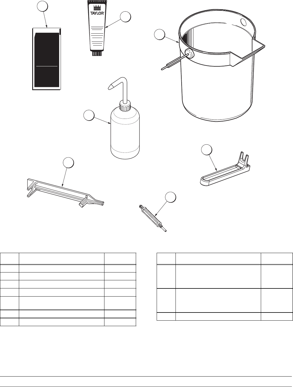
Accessories
KAY-5
Sanitizer/Cleaner
®
CAUTION
KEEP OUT OF REACH OF CHILDREN
FOR INSTITUTIONAL USE ONLY
1 OZ (28.4 g)
L
U
B
E
R
HI
1
4
3
2
5
6
7
Figure 4
ITEM DESCRIPTION PART NO.
1SANITIZER KAY-5 (125 PACKS) 041082
2LUBRICANT-TAYLOR HI-PERF. 048232
3PAIL-MIX 10 QT. 013163
4BOTTLE A.-SQUEEZE X45080
5TOOL-SHAFT-DRIVE PUMP
HPR/LVB 047919
6TOOL-SHAFT-DRIVE PUMP HPR 057167
7TOOL-SEAL-INSTALL/REMOVE 035460
ITEM DESCRIPTION PART NO.
*KIT A.-PARTS TRAY SIMPL PMP
(Consists of 056525 & 044118
Trays - see parts list, page
NO TAG)
X58447
*KIT A.-ACCESSORY PH61
(Consists of X44797 Agitator,
X54704 Cap, 033107 Cap
Restrictor, & 041923 O-Ring)
X48127
*KIT-TUNE UP SIMPL PUMP X49463-63
*NOT SHOWN
14 Model PH61Operator Parts Identification
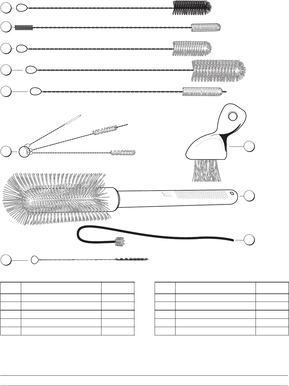
X44127 Brush A.-Package-HT
013071 Black Bristle 1” x 2”
013072 Double Ended
013073 White Bristle 1” x 2”
014753 White Bristle 1-1/2” x 3”
023316 White Bristle 3” x 7”
033059 White Bristle 3” x 1/2”
050103 Set - LVB
0
3
9
7
1
9
Y
e
l
l
o
w
B
r
i
s
t
l
e
1
”
1
2
3
4
5
67
8
9
054068 Pump Spout
10
045079 3-3/4”
Figure 5
ITEM DESCRIPTION PART NO.
1Black Bristle Brush 013071
2Double End Brush 013072
3WhiteBristleBrush(1”x2”) 013073
4White Bristle Brush (1-1/2” x 3”) 014753
5White Bristle Brush (1/2” x 3”) 033059
ITEM DESCRIPTION PART NO.
6Brush Set (3) 050103
7Yellow Bristle Brush 039719
8White Bristle (3” x 7”) 023316
9Brush-Pump Spout 054068
10 Brush-Syrup Port 045079
15
Model PH61 Operator Parts Identification
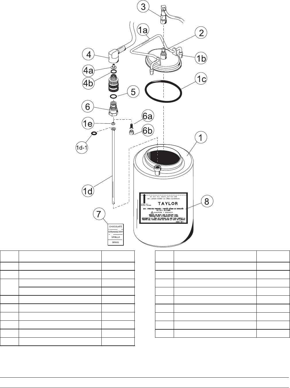
Syrup Tank
ITEM DESCRIPTION PART NO.
1TANK-SYRUP 4 QT. 045533
1a COVER-TANK 035759-1
1b* TIP-NYLON WHITE 042747
TIP-NYLON GREY 024261
1c O-RING-3.437 ID 016037
1d TUBE-DIP SYRUP TANK 015441-7
1d-1 O-RING .291 ID 018550
1e WASHER-1/4 FLARE 018595
2PLUG-Q.D. C02 021077
3SOCKET-QD C02 021524
ITEM DESCRIPTION PART NO.
4SOCKET-QD LIQ. 90 DEG. 021026
4a** RESTRICTOR-SYRUP 030917
4b GASKET-RUBBER 023551
5O-RING-5/8 OD 016030
6PLUG-QD LIQ. 021081
6a VALVE A.-QD PLUG 021081-2
6b INSERT-QD PLUG VALVE 021081-1
7DECAL-SET OF 4 SYRUP FLAV 021523
8DECAL-SYRUP TANK 045533-1
* DUAL SUPPLIER - ORDER AS NEEDED.
**NOT USED ON CHOCOLATE.
16 Model PH61Important: To the Operator
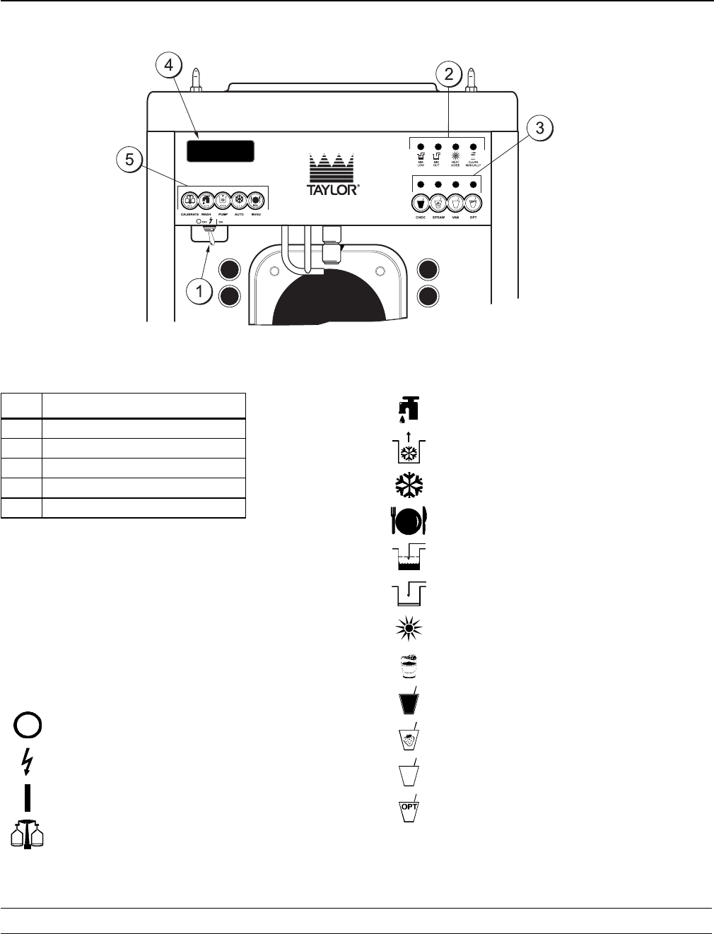
Section 5 Important: To the Operator
Item Description
1Power Switch
2Indicator Lights
3Flavor Selector Keypad
4Liquid Crystal Display
5Keys
Symbol Definitions
To better communicate in the International arena,
the words on many of our operator switches and
buttons have symbols to indicate their functions.
Your Taylor equipment is designed with these
International symbols.
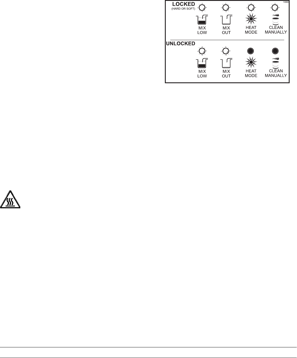
The following chart identifies the symbol definitions
used on the operator switches.
=OFF
=POWER
=ON
=CALIBRATE
= WASH
=PUMP
=AUTO
=MENU
=MIXLOW
= MIX OUT
= HEAT MODE
= CLEAN MANUALLY/BRUSH CLEAN
= CHOCOLATE
= STRAWBERRY
= VANILLA
= OPTIONAL

17
Model PH61 Important: To the Operator
Power Switch
The power switch is located under the control panel
on the left hand side of the unit. When placed in the
ON position, the power switch allows softech panel
operation.
Liquid Crystal Display
The Liquid Crystal Display (LCD) is located on the
front control panel. The LCD is used to show in what
mode the freezer is operating and whether or not
there is sufficient mix.
Indicator Lights
MIX LOW - When the MIX LOW light begins to
flash, it indicates the mix hopper has a low supply of
mix and should be refilled as soon as possible. The
word “LOW” will also display on the LCD indicator
next to the word “MIX”.
MIX OUT - When the MIX OUT light begins to flash,
it indicates the mix hopper has been almost
completely exhausted and has an insufficient supply
of mix to operate the freezer. The word “OUT” will
also display on the LCD indicator next to the word
“MIX”. At this time, the AUTO mode is locked out
and the freezer will be placed in the STANDBY
mode. To initiate the refrigeration system, add mix to
the mix hopper and press the AUTO key. The
freezer will automatically begin operation.
HEAT MODE - When the HEAT MODE light is
flashing, it indicates that the freezer is in the process
of a heat cycle.
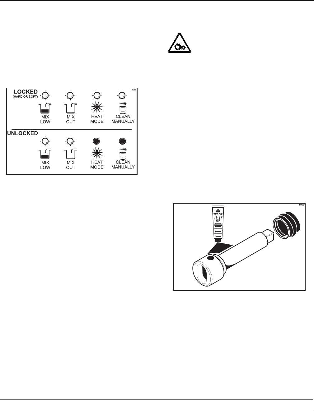
CLEAN MANUALLY - When the CLEAN
MANUALLY light is flashing, it indicates that the
machine must be disassembled and brush cleaned
within 24 hours.
When all four indicator lights are flashing, this
signifies a locked condition. Once a hard lock
condition has been remedied, two lights will remain
flashing until the mix low and mix out conditions
have been satisfied. During a soft lock condition, all
four lights will stop flashing once the unit has been
placed in a heat cycle.
Reset Mechanism
The reset button is located in the right side panel.
The reset mechanism protects the beater motor
from an overload condition. Should an overload
occur, the reset mechanism will trip. To properly
reset the freezer, place the power switch in the OFF
position. Press the reset button firmly. Turn the
power switch to the ON position. Clear the fault.
Press the WASH key and observe the freezer's
performance. Open the side access panel to check if
the beater motor is turning the drive shaft in a
clockwise (from the operator end) direction without
binding.
WARNING: Do not use metal objects to
press the reset button. Failure to follow this
instruction may result in serious electrical shock.
If the beater motor is turning properly, press the
WASH key to cancel the cycle. Press the AUTO key
to resume normal operation. If the freezer shuts
down again, contact a service technician.

18 Model PH61Important: To the Operator
Operating Screen Descriptions
When the machine is powered the system will
initialize. The screen will display “INITIALIZING”.
There will be four types of data the system will
check: LANGUAGE, SYSTEM DATA, CONFIG
DATA, and LOCKOUT DATA. During the
INITIALIZING... LANGUAGE screen, the alarm will
be on. If the system data, configuration data, or
lockout history data has become corrupt, the
following screen will alert the operator that the
system settings may have been changed.
NVRAM FAULT
RESET TO DEFAULTS
PRESS SEL KEY
Once the system has initialized the SAFETY
TIMEOUT screen is displayed and the alarm is
turned on.
SAFETY TIMEOUT
ANY KEY ABORTS
This screen will be displayed, with the alarm on, for
60 seconds or until any key is pressed.
After the safety timeout has been completed, and
the power switch is OFF, one of the following
screens is displayed.
The first screen is displayed if the machine is not in
a brush clean state. If any of the requirements for a
brush clean have not been met, the time displayed
will remain at 5:00 minutes. When all the
requirements for a brush cleaning are met, and the
five minutes expire, the screen will change to the
second screen, which is the standard power switch
OFF screen.
POWER SWITCH OFF
TIME: 4:40
HOPPER: 62.1
BARREL: 67.7
POWER SWITCH OFF
-=-=-=-=-=-
UNIT CLEANED
When the power switch is set in the ON position, the
system mode of operation screen is displayed. In
this example, the machine is ON, but no mode of
operation has been selected. The second line of the
display indicates whether there is a sufficient supply
of mix in the hopper or if there is a LOW or OUT mix
condition. The third line of the display shows the
temperature of the mix hopper. After pressing the
AUTO key, the last line of the display shows the
month and date (MM = month, DD = day) that the
machine needs to be disassembled and brush
cleaned.
MODE: OFF
HOPPER TEMP: 35.5F
UNIT CLEANED
The next display indicates the freezer is operating in
two different modes. The following information is
given:
The machine is operating in the WASH and PUMP
modes, the temperature of the mix hopper is 40_F
(4.4_C), and the machine needs to be brush cleaned
on October 31st.
MODE: WSH-PMP
HOPPER TEMP: 40.0 F
BRUSH CLEAN ON: 10/31
The following displays pertain to the HEAT cycle:
While in the heating phase, you will see this display.
It shows the present temperature of the hopper.
MODE: HEAT
PHASE: HEAT
HOPPER TEMP: 140.0 F
BRUSH CLEAN ON: MM/DD

19
Model PH61 Important: To the Operator
The mix temperature must be raised above 151_F
(66.1_C) within 90 minutes or the freezer will be
locked in STANDBY, and the cycle failure display
will appear.
In the example, the hopper temperature is 140_F
(60_C). The phase shows that the machine is in the
heat phase of the heat treatment cycle.
When the heating phase is complete, the freezer
goes into the holding phase of the cycle. The holding
phase will hold the temperature above 151_F
(66.1_C) for a minimum of 30 minutes.
In this example, the hopper temperature is 151_F
(66.1_C).
MODE: HEAT
PHASE: HOLD
HOPPER TEMP: 151.0 F
BRUSH CLEAN ON: MM/DD
The final phase of the heat treatment cycle is the
cooling phase. Now the freezer must cool the mix
below 41_F(5_C). If the product fails to cool in two
hours, the freezer will lock out.
This example illustrates that the temperature is
being lowered, but has not yet reached the set point.
MODE: HEAT
PHASE: COOL
HOPPER TEMP: 55.0 F
BRUSH CLEAN ON: MM/DD
The entire heat treatment cycle must be completed
in four hours.
When the entire heat cycle has been completed, the
normal display will appear, showing the machine in
the STANDBY mode. The machine may now be
placed in the AUTO mode or left in the STANDBY
mode.
MODE: STANDBY
HOPPER TEMP: 41.0 F
BRUSH CLEAN ON: MM/DD
Hard Lock: There are two causes for a hard lock:
1. Fourteen days have elapsed since the last
brush cleaning. The following screen will be
displayed.
14 DAY TIMEOUT
CLEANING REQ'D
FREEZER LOCKED
PRESS SEL KEY
2. There has been a thermistor failure (freezing
cylinder, hopper, or glycol) during the heat
treatment process.
SYSTEM FAULT
SERVICE REQ'D
FREEZER LOCKED
PRESS SEL KEY
All four LED's on the front of the freezer will light.
Press the SEL key.
The next display is the screen which will appear
after the failure message. To comply with health
codes, heat treatment system freezers must
complete a heat treatment cycle daily, and must
also be brush cleaned every 14 days. Brush
cleaning is the normal disassembly and cleaning
procedures. Failure to follow these guidelines will
cause the control to lock the freezer out of the
AUTO mode. Press the WASH key.
NO AUTO OPERATION
ALLOWED UNTIL
BRUSH CLEANING
PRESS WASH KEY
The next display is the screen which will appear
after the brush cleaning message and illustrates that
the control is in the OFF mode and the machine
needs to be disassembled and brush cleaned.
MODE: OFF
HOPPER TEMP: 45.0 F
FREEZER LOCKED

20 Model PH61Important: To the Operator
Soft Lock: If a heat treatment cycle has not been
initiated within the last 24 hours, all four LED's on
the front of the machine will light and a message will
appear on the LCD. Line 3 of the LCD will indicate
the reason the message appears. Following are the
variable messages which will appear on line 3:
1. POWER SWITCH OFF: Power switch was in
the OFF position.
2. MIX OUT PRESENT: There was mix out
condition present.
3. AUTO OR STANDBY OFF: The unit was not
in the AUTO or STANDBY mode.
4. NO HEAT CYCLE TRIED: A heat treatment
cycle was not attempted in the last 24 hours.
(AUTO HEAT TIME was advanced, or a power
loss was experienced at the time the cycle was
to occur, or a heat cycle failure not due to a
thermistor failure.)
NO HEAT TREAT START
BECAUSE
VARIABLE MESSAGE
PRESS SEL KEY
If the following screen appears, a soft lock has
occurred during the heat treatment cycle.
HEAT TREAT CYCLE
FAILURE
FREEZER LOCKED
PRESS SEL KEY
If the temperature of the product has not fallen
below 41_F(5_C) by the end of the COOL cycle, the
following screen will appear.
PRODUCT OVER TEMP
FREEZER LOCKED
PRESS SEL KEY
Press the SEL key to advance to the next display.
When one of these messages appears, automatic
freezer operation cannot take place until the freezer
is disassembled and brush cleaned or has
completed a heat treatment cycle. The next display
will instruct the operator to start a heat treatment
cycle manually (by pressing the AUTO key), or to
disassemble and brush clean the freezer. If the
AUTO key is pressed, the freezer will automatically
start the heat treatment cycle and only the heat
cycle LED will light.
NO AUTO OPERATION
ALLOWED. PRESS
AUTO FOR HEAT CYCLE
WASH TO BRUSH CLEAN
If the WASH key is pressed, the next display will
appear and the freezer will have to be disassembled
and brush cleaned.
MODE: OFF
HOPPER TEMP: 41.0F
FREEZER LOCKED
Once the freezer is unlocked by starting a heat
treatment cycle, only the heat cycle LED will light. If
the freezer is unlocked by brush cleaning, the mix
low and mix out LED's will light.

21
Model PH61 Important: To the Operator
Operator Menu
The OPERATOR MENU is used to enter the
operator function displays. To access the
OPERATOR MENU, simply press the MENU key.
The cursor will flash over the letter “A” indicating that
this is screen “A”. To select a different screen, use
the arrow keys and move the cursor to the desired
screen selection and press the SEL key.
OPERATOR MENU
A B C D E F G H I J
EXIT FROM MENU
<--- ---> SEL
Screen “B” is FAULT DESCRIPTION. The fault
description will indicate if there is a fault with the
freezer and the side of the freezer where the fault
occurred. To clear the tone for any faults which have
been corrected, press the left arrow key. To see if
there is more than one fault per cylinder, press the
SEL key. When the last fault is displayed, the control
will return to the OPERATOR MENU. To return to
the main screen, move the cursor to “A” and press
the SEL key again. Listed below are the variable
messages which will appear, along with the
corrective action:
1. NO FAULT FOUND: There was no fault found
in the freezer. Nothing will appear on the
screen after this variable message appears.
2. BEATER OVERLOAD: Press the reset button
firmly. Clear the tone.
3. HPCO COMPRESSOR: Place the power
switch in the OFF position. Wait 5 minutes for
the machine to cool. Place the power switch in
the ON position. Clear the tone.
4. COMP ON TOO LONG: Place the power
switch in the OFF position. Call service
technician. Clear the tone.
5. HOPPER THERM BAD: Place the power
switch in the OFF position. Call service
technician.
6. BARREL THERM BAD: Place the power
switch in the OFF position. Call service
technician.
7. GLYCOL THERM BAD: Place the power
switch in the OFF position. Call service
technician.
8. HOPPER OVER TEMP: The hopper
temperature has risen too high as follows. Clear
the tone.
a. The hopper temperature reaches 41_F
(5_C) or higher after a power failure.
b. The hopper temperature has not fallen
below 41_F(5_C) by the end of the COOL
phase in the heat cycle.
9. BARREL OVER TEMP: The barrel temperature
has risen too high as follows. Clear the tone.
a. The barrel temperature reaches 41_F
(5_C) or higher after a power failure.
b. The barrel temperature has not fallen
below 41_F(5_C) by the end of the COOL
phase in the heat cycle.
10. POWER FAILURE: This message will appear
in the FAULT DESCRIPTION if a power failure
has occurred. Clear the tone.
FAULT DESCRIPTION
VARIABLE MESSAGE
CLR SEL
Screen “C” is SET CLOCK. This option allows the
Manager to adjust the control clock date and time.
The date and time may only be changed after the
freezer has been manually cleaned but before it has
been placed in the AUTO or STANDBY mode. The
following message will be displayed if the SET
CLOCK option is selected when the machine is not
in a brush clean state.
SET CLOCK
12:01 7/21/2007
NO CHANGES ALLOWED
Press Any Key

22 Model PH61Important: To the Operator
To change the date or time, select the SET CLOCK
option in the menu. Touch the UP arrow symbol to
advance the arrow from Exit to Change, then touch
the SEL key to select the Change option.
SET CLOCK
12:01 7/21/2007
Change
>Exit
Change the time by touching the UP arrow with the
cursor under the hour position. Move the cursor to
the minutes position by touching the SEL symbol.
Once the correct minutes are entered, touch the
SEL key to advance the cursor to the month.
SET CLOCK
12:01 7/21/2007
>Exit
Enter the correct month, day, and year. Then touch
the SEL symbol to advance to the DAYLIGHT
SAVING TIME screen.
DAYLIGHT SAVING TIME
ENABLED
> Enable
Disable
The Daylight Saving feature, when enabled, will
automatically adjust the control clock for daylight
saving time. To disable the Daylight Saving Time
feature, touch the DOWN arrow to move the arrow
to “Disable”. Then touch the SEL key to save the
new setting.
Screen “D” is SYSTEM INFORMATION. The first
screen will indicate the software version used in the
unit.
SOFTWARE VERSION
PH61 Control UVC2
Version 2.00 SEL
Press the SEL key to view the second screen of the
SYSTEM INFORMATION display. This screen will
indicate the Bill of Material number and serial
number for the unit. Press the SEL key once to
return to the Operator Menu.
B.O.M. PH6133R907
S/N K0000000
SEL
Screen “E” is AUTO HEAT TIME. This screen is
used to set the time of day in which the heat
treatment cycle will start. Move the cursor under the
number you wish to change. Press the plus key to
increase the number; press the minus key to
decrease the number. When the desired time
appears, press the SEL key once to return to the
OPERATOR MENU.
AUTO HEAT TIME
TIME: 12:00 AM
- -
<--- ---> +++ - - - SEL

23
Model PH61 Important: To the Operator
Screen “F” is CURRENT CONDITIONS. This screen
gives the viscosity of the product and the hopper
and barrel temperatures. The last line of the display
is the compressor countdown safety timer. The
safety timer prevents the compressor from running
more than 11 minutes (other than during the cooling
phase of the heat treatment cycle).
Press the SEL key once to view the SERVINGS
COUNTER screen.
VISC HOPPER BARREL
0 38.5 28.5
TIME C 11:00 11:00
The SERVINGS COUNTER screen indicates the
number of times the draw switch has closed
(number of draws) since the last brush cleaning or
since the last serving counter reset. A maximum of
32,767 draws can be recorded; an additional draw
will cause the counter to restart at zero. Pressing the
MENU key/SEL will return the display to the
Operator Menu.
SERVINGS COUNTER
DRAWS
12 SEL
Draws are counted during the AUTO mode of
operation only.
Screen “G” is HEAT CYCLE DATA. The information
from the previous heat treatment cycles can be
obtained through this screen. The most recent heat
treatment cycle data will be shown first; press the
plus key to scroll through the remaining heat cycle
displays. If a heat treatment cycle failure should
occur, a 2 character message will appear on the
second line of the screen. Press the SEL key once
to return to the OPERATOR MENU.
Listed below are the variable messages which could
appear:
HT Failure in the heating phase.
CL Failure in the cooling phase.
TT Failure in meeting total heat treatment cycle
time requirement.
MO Mix out condition.
OP Operator interruption.
PF Power failure. (If a power failure occurs, but
the heat treatment cycle does not fail, an
asterisk (*) will appear on the third line of the
display.)
BO Beater overload.
HO High pressure cut-out.
TH Failed thermistor probe.
PS Power switch placed in the OFF position.
ML Mix Low Condition.
14 14 Day Timeout Occurred.
RC Heat Cycle Record Cleared.
11/07 02:00 05:09
HEAT OVER COOL XX
01:09 00:45 01:14
TEMP AT END 38.5 1
Pressing the left arrow key on any HEAT CYCLE
DATA screen will cause the extended data screen to
be displayed. This screen shows the hopper, barrel,
and glycol temperatures, and the amount of time the
freezer spent in the phases of the heat cycle when
the heat cycle completed, or was terminated.
HOPPER BARREL GLYCOL
151.0 134.5 178.0
PHASE TIME: 1:20 1

24 Model PH61Important: To the Operator
Screen “H” is the LOCKOUT HISTORY. This screen
displays a history of the last 40 hard locks, soft
locks, and brush clean dates. Page numbers are
indicated in the upper right hand corner. Page 1
always contains the most recent failure. Press the
PUMP key to cycle through the pages.
The second line of the screen displays the date and
time a failure occurs. The third line indicates the
reason for a failure, or will indicate a successful
brush cleaning has occurred. Some failures occur
for multiple reasons. When this occurs, a page will
be generated for each reason. Press the SEL key
once to return to the Operator Menu, or twice to
return to the Main Screen.
LOCKOUT HISTORY 1
7/21/07 02:08
SOFTLOCK ABORT+++ - - - SEL
Screen “I” is the SERVICE MENU. This screen can
only be accessed by a service technician.
Screen “J” is the STANDBY MODE. To place the
freezer in the STANDBY mode, move the cursor
under the word “yes”. Press the SEL key to execute
the command. Pressing the SEL key again will
return you to the main screen. To exit the STANDBY
mode and place the unit in AUTO, press the AUTO
key once. Pressing the AUTO key again will place
the unit in the OFF mode.
STANDBY MODE
STANDBY YES NO - - -
<--- ---> SEL
25
Model PH61 Operating Procedures
Section 6 Operating Procedures
Equipment Set Up
Evaluate the condition of lights and screen
messages (Hard Lock or Soft Lock, etc.) before
performing opening procedures. If all four LED's on
the front of the unit are lit, the unit is locked.
(See Figure 6.)
Figure 6
We begin our instructions at the point where we
enter the store in the morning and find the parts
disassembled and laid out to air dry from the
previous night's cleaning.
These opening procedures will show you how to
assemble these parts into the freezer, sanitize them,
and prime the freezer with fresh mix in preparation
to serve your first portion.
If you are disassembling the machine for the first
time or need information to get to the starting point
in our instructions, turn to the Closing Procedures on
page 45, and start there.
Freezing Cylinder Assembly
Make sure the power switch is in the
OFF position. Failure to follow this instruction may
result in severe personal injury from hazardous
moving parts.
With the parts tray available:
Step 1
Before installing the shake beater drive shaft,
lubricate the groove on the beater drive shaft. Slide
the beater drive shaft boot seal over the small end of
the beater drive shaft and engage into the groove on
the shaft. Heavily lubricate the inside portion of the
boot seal and also lubricate the flat end of the boot
seal that comes in contact with the rear shell
bearing.
Apply an even coat of lubricant to the shaft. DO
NOT lubricate the square end. (See Figure 7.)
Note: When lubricating parts, use an approved food
grade lubricant (example: Taylor Lube HP).
Figure 7
26 Model PH61Operating Procedures
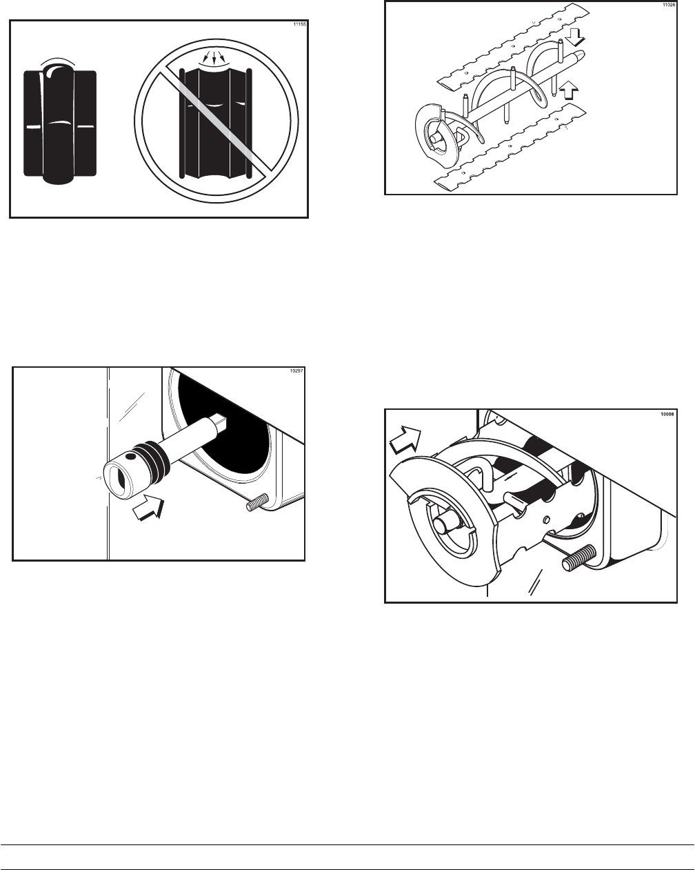
Note: To ensure that the mix does not leak out of
the back of the freezing cylinder, the middle section
of the boot seal should be convex or extend out from
the seal. If the middle section of the boot seal is
concave or extending into the middle of the seal,
turn the seal inside out. (See Figure 8.)
Figure 8
Step 2
Install the beater drive shaft through the rear shell
bearing in the freezing cylinder and engage the
square end firmly into the drive shaft coupling. Be
sure the drive shaft fits into the drive coupling
without binding. (See Figure 9.)
Figure 9
Step 3
Check scraper blades for any nicks or signs of wear.
If any nicks are present, replace the blades.
Note: Scraper blades should be replaced every 6
months.
Step 4
If blades are in good condition, place each scraper
blade over the holding pins on the beater assembly.
(See Figure 10.)
Figure 10
Note: The holes in the scraper blade must fit over
the pins to prevent damage.
Step 5
Hold the blades on the beater assembly. Insert the
back of the beater assembly into the freezing
cylinder and connect the drive hole with the drive
shaft. (See Figure 11.)
Figure 11
Note: When properly seated, the beater will not
protrude beyond the front of the freezing cylinder.
27
Model PH61 Operating Procedures
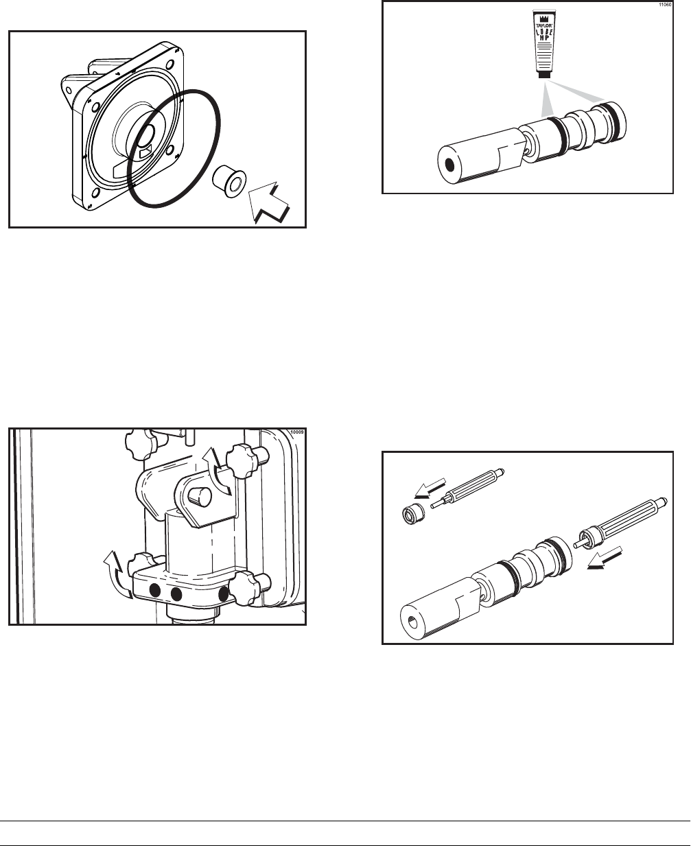
Step 6
Place the freezer door o-ring into the groove on the
back of the freezer door. DO NOT lubricate the
o-ring. Lubricate the outside diameter of the front
bearing. Slide the front bearing into the door hub.
(See Figure 12.)
11272
Figure 12
Step 7
Position the freezer door on the 4 studs on the front
of the freezing cylinder. Install the handscrews.
Tighten equally in a criss-cross pattern to insure the
door is snug. Do not over-tighten. (See Figure 13.)
Figure 13
Step 8
Assemble the draw valve spinner assembly. Inspect
draw valve o-rings for cuts or nicks. (Replace if cut
or nicked.) If draw valve o-rings are in good
condition, slide the 2 o-rings into the grooves of the
draw valve and lubricate. (See Figure 14.)
Figure 14
Step 9
Lubricate the outer diameter of the spinner shaft
seal. Fill the cups on each end of the seal with
lubricant. Insert the spinner shaft seal into the
bottom of the draw valve as far as it will go. The
spinner shaft seal should fit into the seal groove
located inside the draw valve cavity.
Important: Inspect to see that the spinner shaft
seal is correctly installed in the groove. A worn,
missing, or improperly installed spinner shaft seal
will cause product leakage out the top of the draw
valve. (See Figure 15)
11062
Figure 15
28 Model PH61Operating Procedures
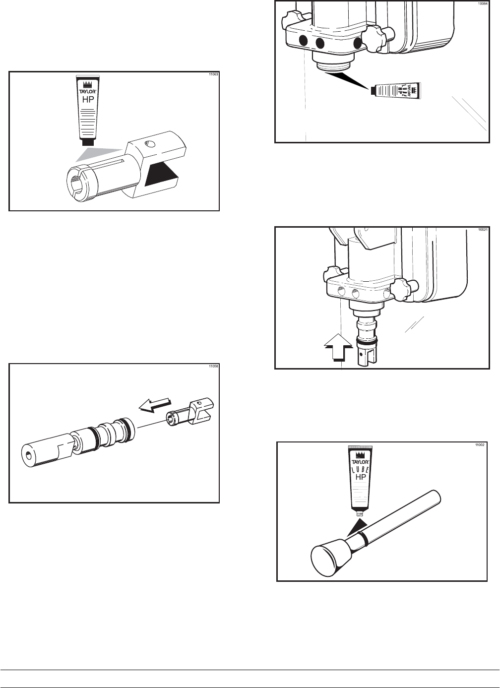
Step 10
Lubricate the smaller end of the driven spinner.
(See Figure 16.)
Figure 16
Step 11
Squeezing the split end together, insert the driven
spinner through the metal opening of the draw valve
until it snaps into place. (See Figure 17.)
Figure 17
Step 12
Lubricate the inside of the freezer door spout, top
and bottom. (See Figure 18.)
Figure 18
Step 13
Insert the draw valve spinner assembly from the
bottom until the slot in the draw valve which accepts
the draw handle comes into view. (See Figure 19.)
Figure 19
Step 14
Install and lubricate the pivot pin o-ring.
(See Figure 20.)
Figure 20
29
Model PH61 Operating Procedures
Step 15
With the stopping tab of the draw handle facing
down, slide the fork of the draw handle into the slot
of the draw valve. Secure the draw handle with the
pivot pin. (See Figure 21.)
Figure 21
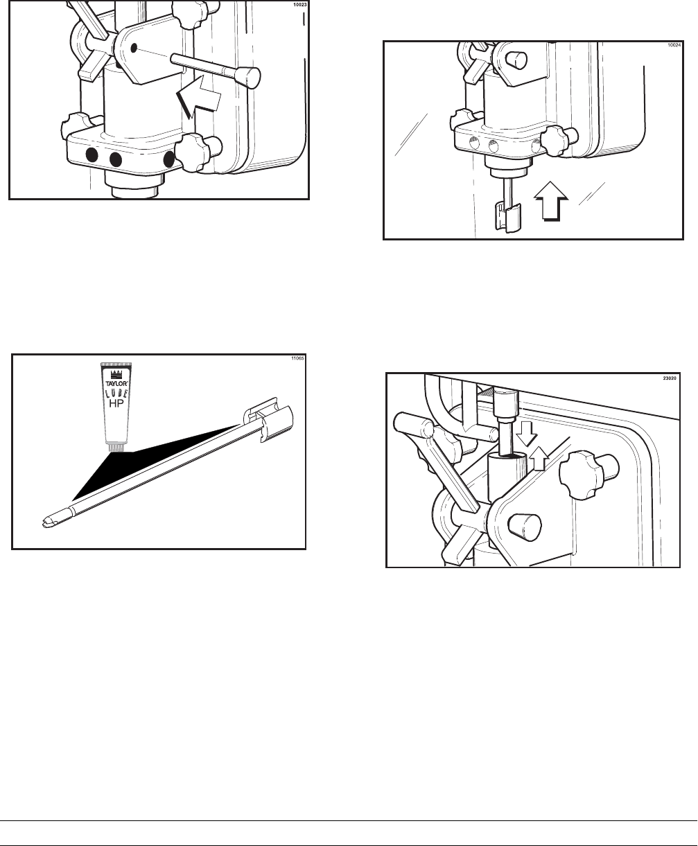
Step 16
Lubricate the shaft of the spinner blade up to the
groove. (See Figure 22.)
Figure 22
Step 17
Insert the spinner blade shaft from the bottom, into
the center of the driven spinner, and up through the
draw valve cavity until the shaft appears at the top of
the draw valve. The spinner blade must be aligned
and engaged to the driven spinner at the bottom.
This allows the spinner shaft to raise high enough to
be engaged into the spinner coupling at the top.
(See Figure 23.)
Figure 23
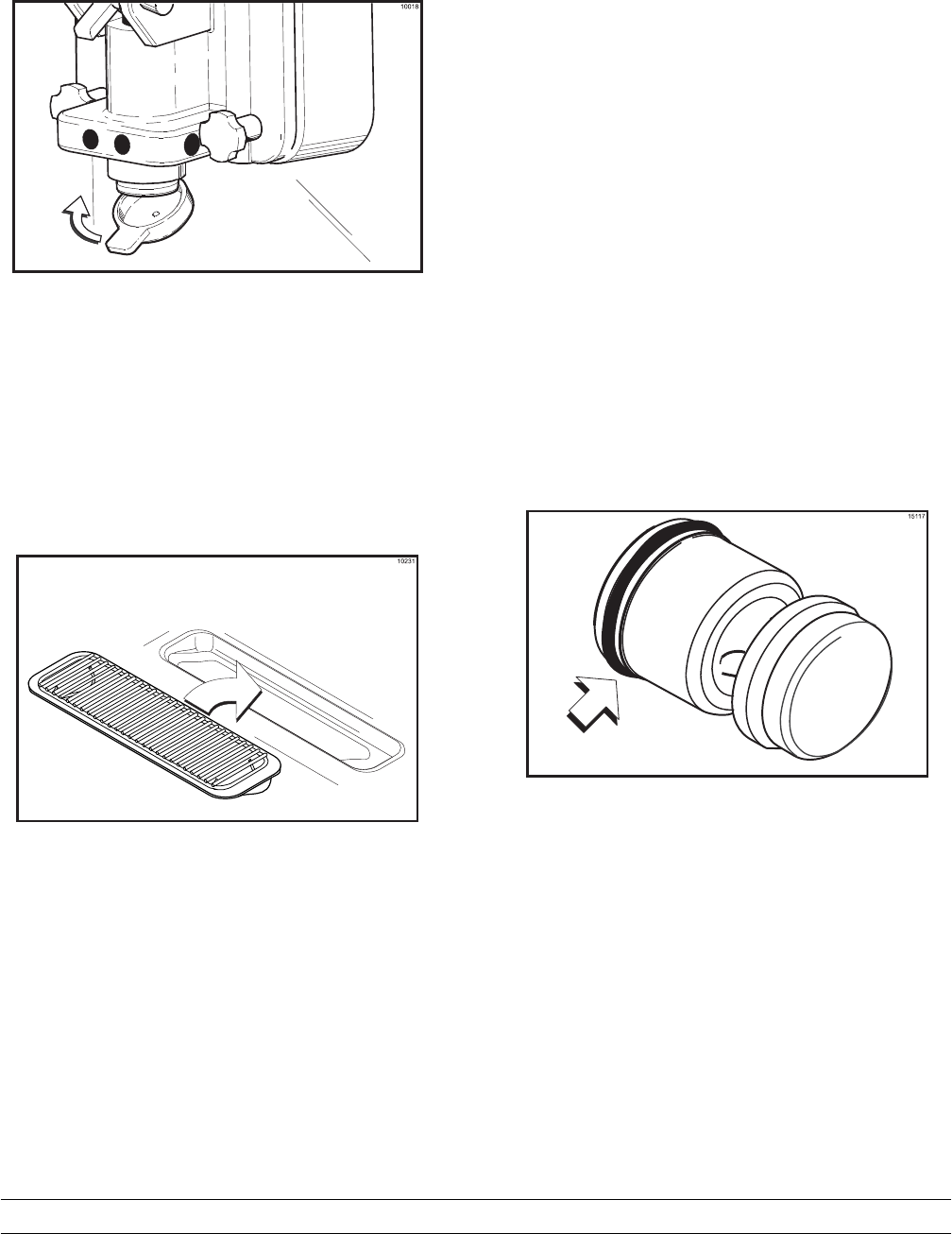
Step 18
Raise the locking collar of the spinner coupling and
insert the spinner shaft into the cavity of the coupling
until the locking collar can drop into the locked
position. (See Figure 24.)
Figure 24
30 Model PH61Operating Procedures
Step 19
Snap the restrictor cap over the end of the door
spout. (See Figure 25.)
Figure 25
Step 20
Slide the long drip pan into the hole in the front
panel.
Step 21
Slide the short drip pan into the hole in the rear
panel.
Step 22
Install the front drip tray and splash shield under the
door spout. (See Figure 26.)
Figure 26
Mix Hopper Assembly
With the parts trays available:
Step 1
Inspect the rubber pump parts. O-rings and gasket
must be in 100% good condition for the pump and
entire machine to operate properly. The o-rings and
gasket cannot properly serve their intended function
if nicks, cuts, or holes in the material are present.
Replace any defective parts immediately and
discard the old.
Step 2
Assemble the piston. Slide the red o-ring into the
groove of the piston. DO NOT lubricate the o-ring.
(See Figure 27.)
Figure 27
31
Model PH61 Operating Procedures
Step 3
Apply a thin layer of lubricant to the inside of the
pump cylinder at the retaining pin hole end.
(See Figure 28.)
15130
L
U
B
E
R
Figure 28
Step 4
Insert the piston into the retaining pin hole end of the
pump cylinder. (See Figure 29.)
15118
Figure 29
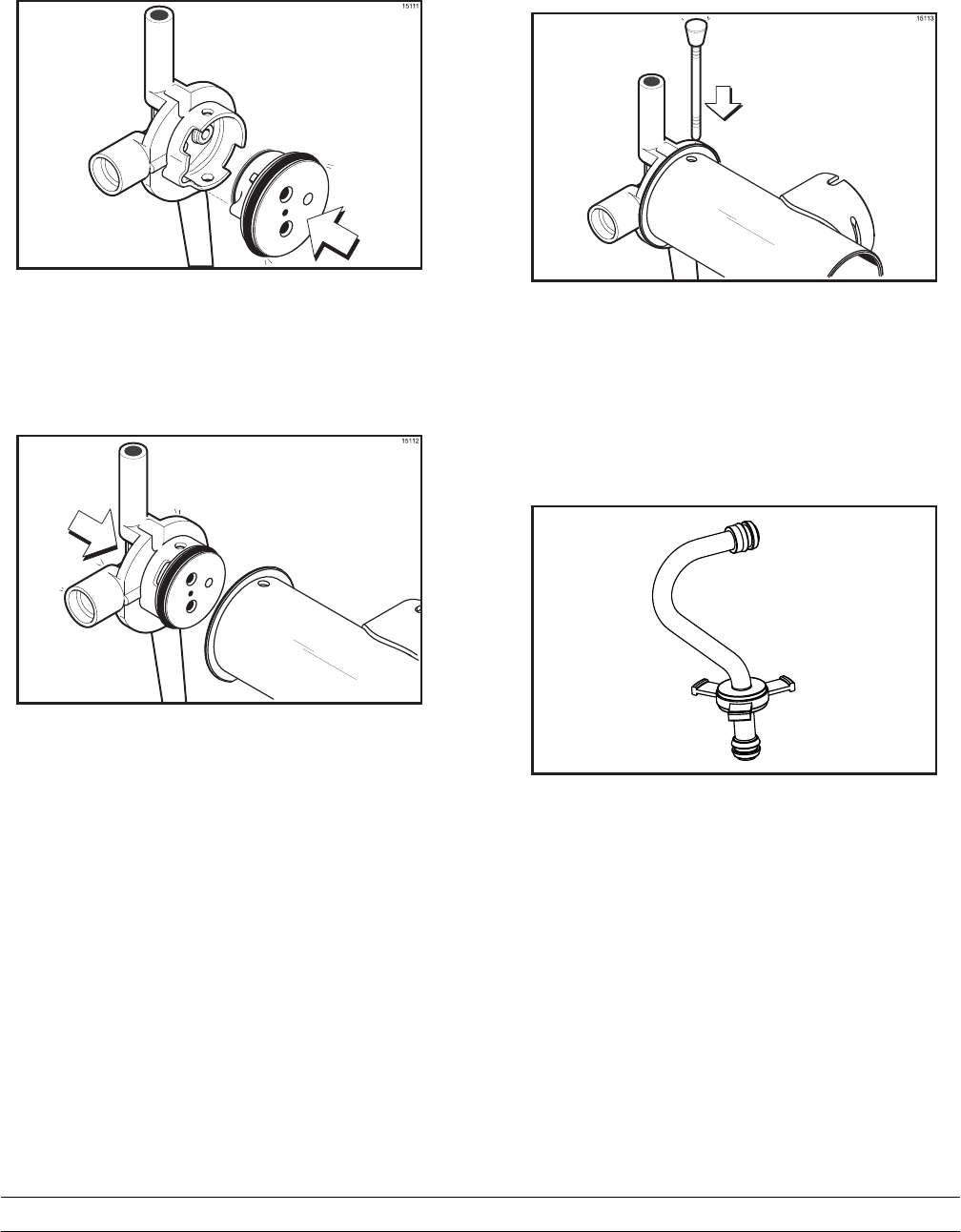
Step 5
Assemble the valve cap. Slide the red o-ring into the
groove of the valve cap. DO NOT lubricate the
o-ring. (See Figure 30.)
15109
Figure 30
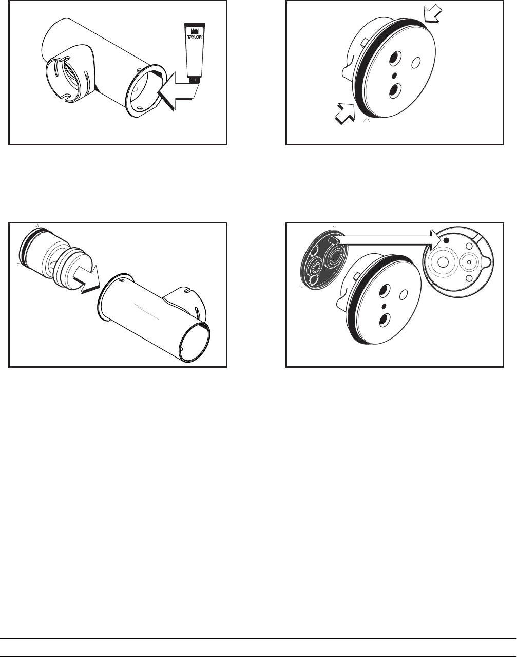
Step 6
Slide the pump valve gasket into the holes on the
cap. DO NOT lubricate the gasket. (See Figure 31.)
15110
Figure 31
32 Model PH61Operating Procedures
Step 7
Insert the valve cap into the hole in the mix inlet
adapter. (See Figure 32.)
Figure 32
Step 8
Insert the mix inlet assembly into the pump cylinder.
(See Figure 33.)
Figure 33
Note: The adapter must be positioned into the
notch located at the end of the pump cylinder.
Step 9
Secure the pump parts in position by sliding the
retaining pin through the cross holes located at one
end of the pump cylinder. (See Figure 34.)
Figure 34
Note: The head of the retaining pin should located
at the top of the pump when installed.
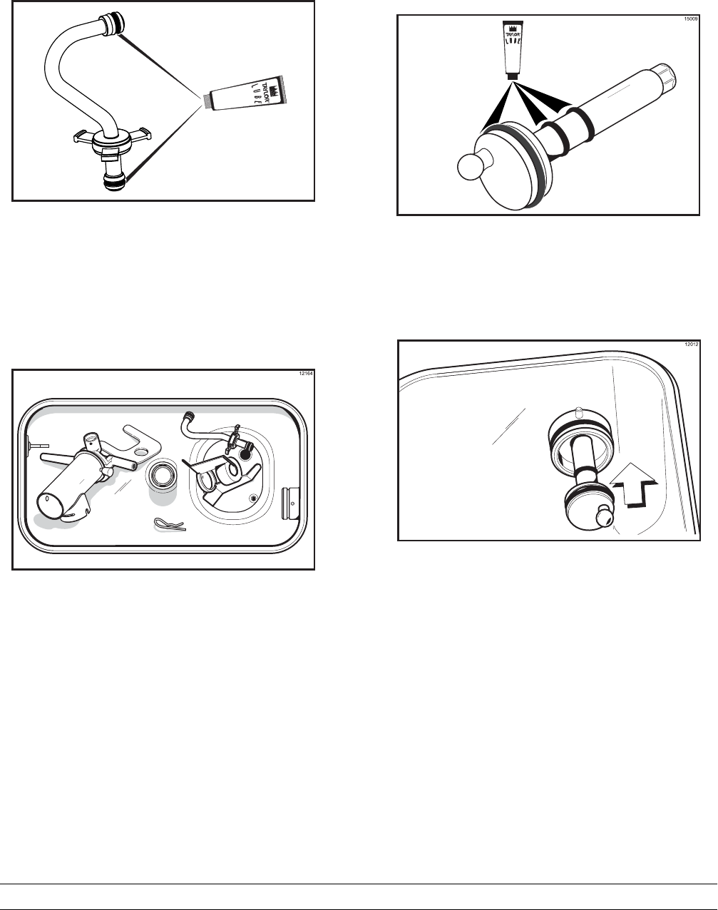
Step 10
Assemble the feed tube assembly. Slide the check
ring into the groove of the feed tube.
(See Figure 35.)
15120
Figure 35
33
Model PH61 Operating Procedures
Step 11
Install one red o-ring on each end of the mix feed
tube, and thoroughly lubricate. (See Figure 36.)
15121
Figure 36
Step 12
Lay the pump assembly, pump clip, feed tube, cotter
pin and agitator in the bottom of the mix hopper for
sanitizing. (See Figure 37.)
Figure 37
Step 13
Slide the large black o-ring and the two smaller
black o-rings into the grooves on the drive shaft.
Thoroughly lubricate the o-rings and shaft. DO NOT
lubricate the hex end of the shaft. (See Figure 38.)
Figure 38
Step 14
Install the hex end of the drive shaft into the drive
hub at the rear wall of the mix hopper.
(See Figure 39.)
Figure 39
Note: For ease in installing the pump, position the
ball crank of the drive shaft in the 3 o'clock position.
34 Model PH61Operating Procedures
080910
Sanitizing
Step 1
Prepare a pail of approved 100 PPM sanitizing
solution (examples: 2-1/2 gal. [9.5 liters] of Kay-5R
or 2 gal. [7.6 liters] of Stera-SheenR). USE WARM
WATER AND FOLLOW THE MANUFACTURER'S
SPECIFICATIONS.
Step 2
Pour the sanitizing solution over all parts in the
bottom of the mix hopper and allow it to flow into the
freezing cylinder.
Note: You have just sanitized the mix hopper
and parts; therefore, be sure your hands are
clean and sanitized before going on in these
instructions.
Step 3
Using the white hopper brush, clean the mix level
sensing probes, the mix hopper, mix inlet hole, the
outside of the agitator drive shaft housing, the
agitator, the air/mix pump, pump clip, mix feed tube
and cotter pin.
Step 4
Prepare another pail of approved 100 PPM
sanitizing solution (examples: 2-1/2 gal. [9.5 liters] of
Kay-5Ror 2 gal. [7.6 liters] of Stera-SheenR).
USE WARM WATER AND FOLLOW THE
MANUFACTURER'S SPECIFICATIONS.
Step 5
Install the air/mix pump assembly at the rear of the
mix hopper. To position the pump on the drive hub,
align the drive slot in the piston with the drive crank
of the drive shaft. Secure the pump in place by
slipping the pump clip over the collar of the pump,
making sure the clip fits into the grooves in the
collar. (See Figure 40.)
Figure 40
Step 6
Note: Install the pump end of the mix feed tube
and secure with the cotter pin. Failure to follow
this instruction could result in sanitizer spraying on
the operator.
Step 7
Pour the sanitizing solution into the mix hopper. The
sanitizing solution should be within 1” (25 mm) of the
top of the hopper.
Step 8
Using the white hopper brush, scrub the exposed
sides of the hopper.
Step 9
Place the power switch to the ON position.
Step 10
Press the WASH key. This will cause the sanitizing
solution in the freezing cylinder to come in contact
with all areas of the freezing cylinder. Allow the
sanitizing solution to agitate for five minutes.
(See Figure 41.)
Figure 41
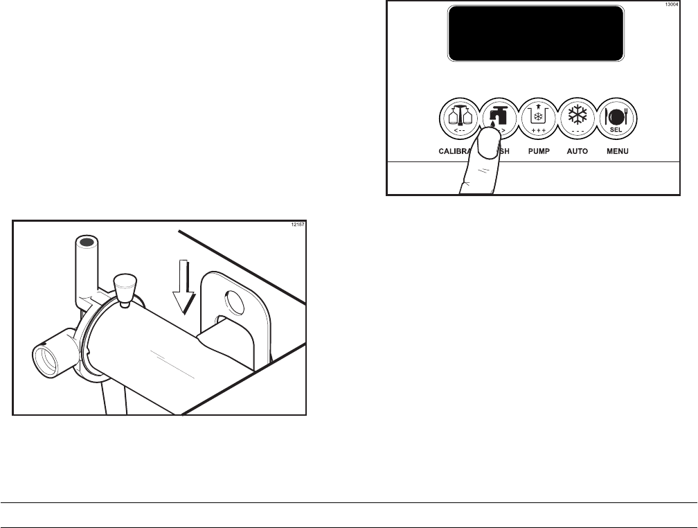
Step 11
With a pail beneath the door spout, open and close
the draw valve six times.
Step 12
Press the PUMP key to sanitize the inside of the
air/mix pump.
Step 13
Open the draw valve and draw off all the remaining
sanitizing solution.
35
Model PH61 Operating Procedures
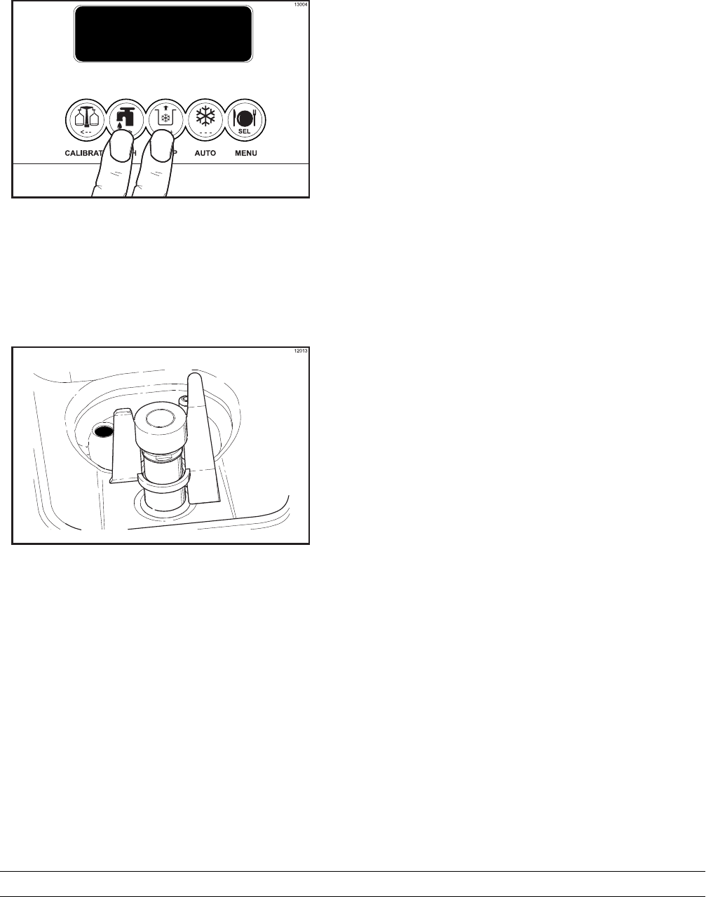
Step 14
Press the WASH and PUMP keys to stop the WASH
and PUMP modes. Close the draw valve.
(See Figure 42.)
Figure 42
Note: Be sure your hands are clean and
sanitized before going on in these instructions.
Step 15
Place the agitator on the agitator drive shaft
housing. (See Figure 43.)
Figure 43
Note: If the agitator paddle should stop turning
during normal operation, with sanitized hands,
remove the agitator from the agitator drive shaft
housing and brush clean with sanitizing solution.
Install the agitator back onto the agitator drive shaft
housing.
Step 16
Remove the restrictor cap.
Step 17
Return to the freezer with a small amount of
sanitizing solution. With a pail below the door spout,
dip the door spout brush into the sanitizing solution
and brush clean the syrup ports in the freezer door,
door spout, bottom of the driven spinner and spinner
blade, and syrup line fittings.
To assure sanitary conditions are maintained, brush
clean each item for a total of 60 seconds, repeatedly
dipping the brush in sanitizing solution.
Step 18
With the syrup port brush, brush each syrup port
hole10to15times.Dipthebrushinsanitizing
solution before brushing each port.
Step 19
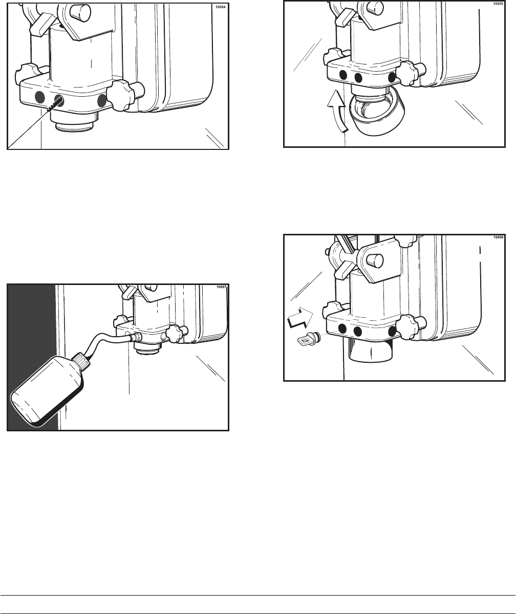
Fill the squeeze bottle with sanitizing solution. With a
pail beneath the door, insert the tube end of the
squeeze bottle into the syrup port, and squeeze the
bottle firmly. This action will force solution out of the
adjacent port and down around the spinner.
This procedure should be performed for at least 10
seconds per port.
Step 20
Install the syrup valves and the restrictor cap.
Priming
Note: Evaluate the condition of LED's (lights) and
screen messages before performing priming
procedures. If all 4 LED's are flashing, the unit is
locked.
Step 1
With a mix pail beneath the door spout, open the
draw valve. Pour 2-1/2 gallons (9.5 liters) of FRESH
mix into the mix hopper and allow it to flow into the
freezing cylinder. This will force out any remaining
sanitizing solution. When only mix is flowing from the
door spout, close the draw valve.
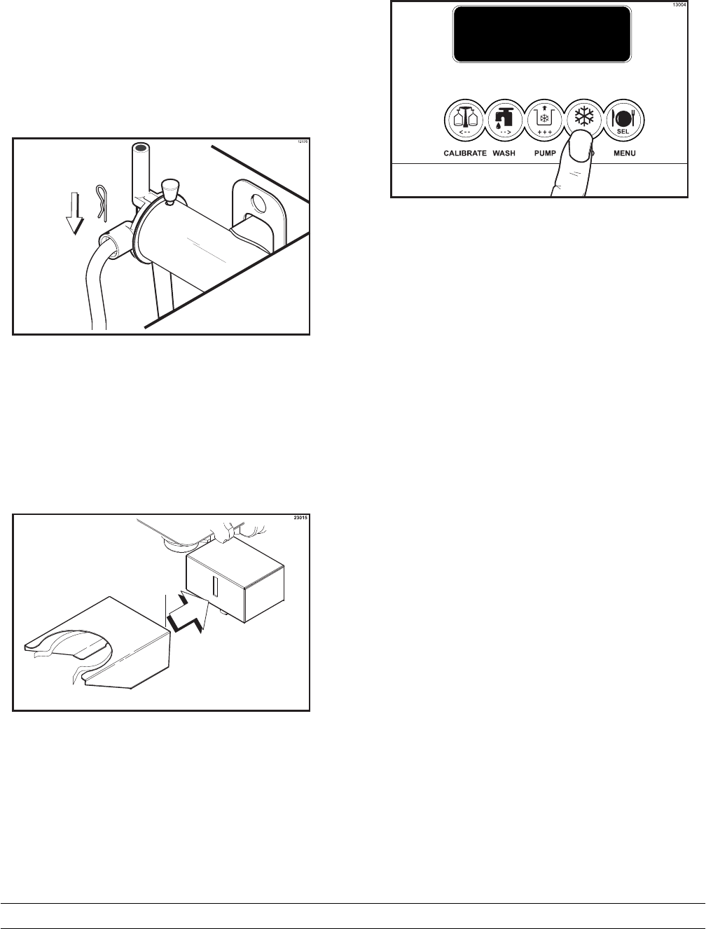
36 Model PH61Operating Procedures
Step 2
When mix stops bubbling down into the freezing
cylinder, remove the cotter pin from the outlet fitting
of the mix pump. Remove the mix feed tube. Insert
the outlet end of the mix feed tube into the mix inlet
hole in the mix hopper. Place the inlet end of the mix
feed tube into the outlet fitting of the mix pump.
Secure with the cotter pin. (See Figure 44.)
Figure 44
Step 3
Install the shake cup holder. (See Figure 45.)
Figure 45
Step 4
Press the AUTO key. (See Figure 46.)
Figure 46
Step 5
Fill the hopper with fresh mix and place the mix
hopper cover in position.
Use only FRESH mix when priming the freezer.
IMPORTANT: When drawing product, allow the
draw handle to close automatically. Manually
closing the draw handle will damage the syrup
valve and cause serious syrup flavor carryover.
Daily Closing Procedures
This procedure must be done at the close of
business.
The function of the Heat Treatment Cycle is to destroy
bacteria by raising the temperature of the mix in the
freezing cylinder and the hopper to a specified
temperature for a specified period of time, and then
bringing the temperature back down low enough to
retard spoilage.
The Heat Treatment Cycle will start at the time
designated in the Auto Heat Time.
IMPORTANT: The level of mix in the hoppers
must be high enough to cover the agitator
paddles.
Note: If the CLEAN MANUALLY light is flashing, do
not add mix. The machine must be disassembled
and brush cleaned within 24 hours.
37
Model PH61 Operating Procedures
The freezer must be in the AUTO or STANDBY
mode before the HEAT cycle may be started.
(See Figure 47.)
MODE: AUTO
MIX: OK
HOPPER 40.0F
BRUSH CLEAN ON: MM/DD
Figure 47
Step 1
Remove the hopper cover, shake cup holder, front
drip tray, splash shield, and all three drip pans (two
from the rear panel and one from the front panel).
Make sure your hands are clean and sanitized
before performing these next steps.
Note: Pressing the CAL key will stop agitator
movement for 10 seconds. The agitator will
automatically restart after 10 seconds.
Step 2
Remove the agitator from the mix hopper and the
restrictor cap from the freezer door spout.
Step 3
Take the agitator, hopper cover, shake cup holder,
drip pans, front drip tray, splash shield and restrictor
cap to the sink for further cleaning and sanitizing.
Take the syrup hole plugs, spout cap, and spout cap
o-ring to the sink for further cleaning and sanitizing.
Step 4
Rinse these parts in cool, clean water.
Step 5
Prepare a small amount of an approved 100 PPM
cleaning solution (example Kay-5® or
Stera-Sheen®).USE WARM WATER AND
FOLLOW THE MANUFACTURER'S
SPECIFICATIONS.
Step 6
Brush clean the parts.
Step 7
Place the restrictor cap, front drip tray, shake cup
holder and splash shield on a clean, dry surface to
air-dry overnight or until the heating cycle is
complete.
Step 8
Prepare a small amount of an approved 100 PPM
sanitizing solution (example Kay-5® or Stera-
Sheen®). USE WARM WATER AND FOLLOW THE
MANUFACTURER'S SPECIFICATIONS.
Step 9
Sanitize the syrup hole plugs, spout cap, spout cap
o-ring, rear drip pan, agitator, and hopper cover.
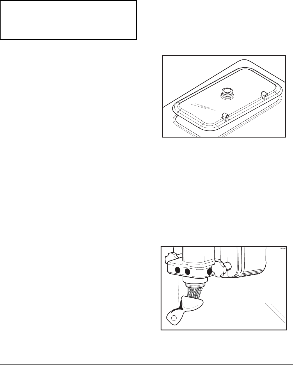
Step 10
Install the agitator back onto the agitator drive shaft
housing. Replace the hopper cover. (See Figure 48.)
12156
Figure 48
Important: If you do not install the agitator correctly,
the machine will fail the heat cycle and will lock out
in the morning.
Step 11
Remove the syrup lines from the freezer door.
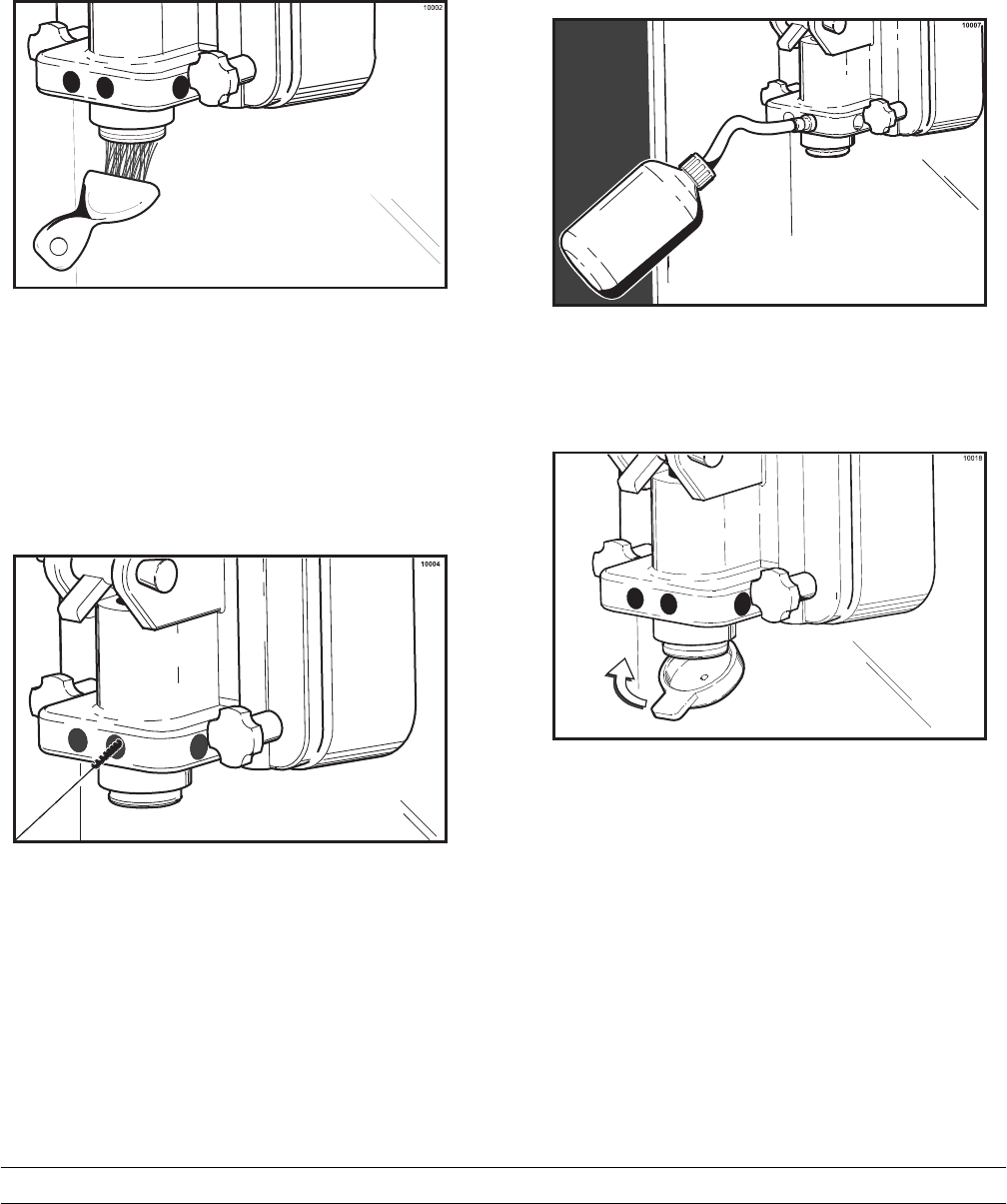
Step 12
Return to the freezer with a small amount of
cleaning solution. With a pail below the door spout,
dip the door spout brush into the cleaning solution
and brush clean the syrup ports in the freezer door,
door spout and bottom of the driven spinner, spinner
blade, and syrup line fittings. (See Figure 49.)
Figure 49
38 Model PH61Operating Procedures
Note: To assure sanitary conditions are maintained,
brush each item for a total of 60 seconds, repeatedly
dipping the brush in cleaning solution.
Step 13
With the syrup port brush, brush each syrup port
hole 10 to 15 times. Dip the brush in the cleaning
solution before brushing each port. (See Figure 50.)
Figure 50
Step 14
Fill the squeeze bottle with cleaning solution. With a
pail beneath the door, insert the tube end of the
squeeze bottle into each syrup port and squeeze the
bottle firmly. This action will force solution out of the
adjacent port and down around the spinner. This
procedure should be performed for at least 10
seconds per port. (See Figure 51.)
Figure 51
Step 15
Place the spout cap o-ring in the spout cap. Fill the
spout cap with sanitizing solution. While holding the
draw valve closed, install the spout cap over the end
of the door spout. This will cause sanitizing solution
to back flow through the syrup ports.
(See Figure 52.)
Figure 52
Step 16
Install the syrup hole plugs in the syrup ports in the
freezer door. (See Figure 53.)
Figure 53
Step 17
Remove, clean and reinstall the long drip pan
through the front panel.
39
Model PH61 Operating Procedures
Step 18
Install the short drip pan in the rear panel.
Step 19
Use a clean, sanitized towel and wipe down the
freezer door and area around the bottom of the
freezer door.
The heat cycle will start when the clock on the
machine reaches the AUTO HEAT TIME set in the
Operator Menu (see page 21).
There are 3 phases of the heat cycle: Heating,
Holding and Cooling. Each phase has a time limit. If
any one of the three phases fail to reach the proper
temperatures within the time limit, the cycle will
automatically abort and return to the STANDBY
mode. The LCD will display the message: HEAT
TREAT CYCLE FAILURE - FREEZER LOCKED -
PRESS SEL KEY. The product may not be safe to
serve. The freezer will be locked out (softlock) of the
AUTO mode. The operator will be given the option
of pressing the AUTO key which will begin a new
heat cycle, or pressing the WASH key which will
place the freezer into the OFF mode to allow a
brush clean of the machine.
Note: Once the heating cycle has started, it cannot
be interrupted. The heating cycle will take a
maximum of 4 hours to complete with a full hopper.
DO NOT attempt to draw product or
disassemble the unit during the HEAT cycle. The
product is hot and under extreme pressure.
When the heating cycle is complete, the control will
return to the STANDBY mode.
Daily Opening Procedures
Evaluate the condition of LED's (lights) and screen
messages (Hard Lock or Soft Lock, etc.) before
performing opening procedures. As indicated in the
illustration below, 4 flashing LED's, indicate a
“locked” condition. (See Figure 54.)
Figure 54
Set-Up - Complete The Following
Make sure your hands are clean and sanitized
before performing these next steps.
Step 1
When the heating cycle is complete, the normal
display will appear, showing the machine in the
STANDBY mode.
Step 2
Prepare a small amount of an approved 100 PPM
sanitizing solution (example Kay-5® or
Stera-Sheen®).USE WARM WATER AND
FOLLOW THE MANUFACTURER'S
SPECIFICATIONS.
Step 3
Remove the syrup hole plugs and spout cap with
o-ring from the freezer door. Sanitize the restrictor
cap, syrup hole plugs, spout cap and o-ring, shake
cup holder, front drip tray and splash shield, in this
solution.
40 Model PH61Operating Procedures
Step 4
Return to the freezer with a small amount of
sanitizing solution. With a pail below the door spout,
dip the door spout brush into the sanitizing solution
and brush clean the syrup ports in the freezer door,
door spout, bottom of the driven spinner and spinner
blade, and syrup line fittings. (See Figure 55.)
Figure 55
Note: To assure sanitary conditions are maintained,
brush clean each item for a total of 60 seconds,
repeatedly dipping the brush in sanitizing solution.
Step 5
With the syrup port brush, brush each syrup port
hole10to15times.Dipthebrushinsanitizing
solution before brushing each port. (See Figure 56.)
Figure 56
Step 6
Fill the squeeze bottle with sanitizing solution. With a
pail beneath the door, insert the tube end of the
squeeze bottle into the syrup port, and squeeze the
bottle firmly. This action will force solution out of the
adjacent port and down around the spinner. This
procedure should be performed for at least 10
seconds per port. (See Figure 57.)
Figure 57
Step 7
Install the restrictor cap on the freezer door spout.
(See Figure 58.)
Figure 58
Step 8
Using a clean, sanitized towel, wipe down the
freezer door and area around the bottom of the
freezer door.
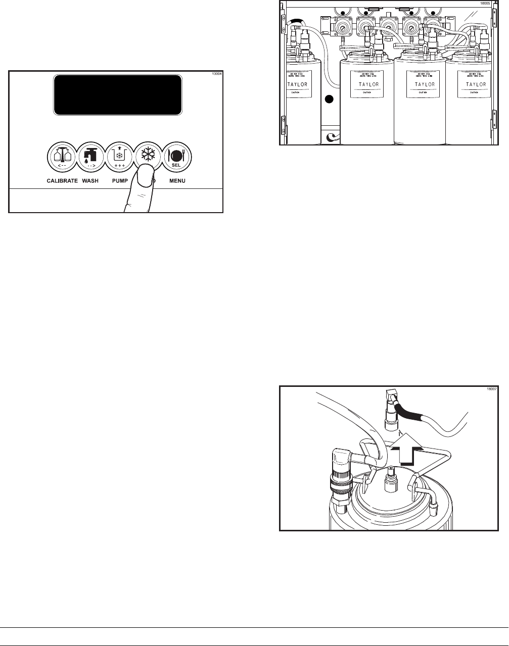
41
Model PH61 Operating Procedures
Step 9
Install the shake cup holder, the front drip tray, and
the splash shield.
Step 10
When ready to resume normal operation, press the
AUTO key. (See Figure 59.)
Figure 59
Note: This procedure should be done 3-4 hours
before the first shake is served, to build up ice crystals.
Syrup System
Two main objectives in your opening procedures
must be to: (1) fill the syrup tanks, and (2) calibrate
the syrup flow. This must be checked daily to insure
the high quality shake you desire.
Discard syrup weekly and flush syrup lines at least
once a week. This will prevent syrup clogging the
lines and will break the bacteria chain. See page 49
to sanitize the syrup system.
The syrup tanks are located in the lower front syrup
compartment. The syrup lines are color spiral
wrapped. Be sure to match the color wrapped syrup
line to the correct syrup flavor. (See Figure 60.)
Figure 60
Note: Vanilla and strawberry syrup lines use
restrictors at the syrup tank quick disconnect
connection to maintain proper calibration. If thin
viscosity syrups are used in the special tank, it will
be necessary to install a restrictor in the syrup line
connection.
Unscrew the quick disconnect from the elbow
portion of the syrup line. Make sure the o-ring rests
on the end of the quick disconnect fitting. Place the
restrictor on top of the o-ring and screw the quick
disconnect back onto the syrup line.
Step 1
Filling the syrup tanks: Pull back on the collar of
the quick disconnect fitting for the air line. Allow the
air pressure to escape from the syrup tank. (See
Figure 61.)
Figure 61
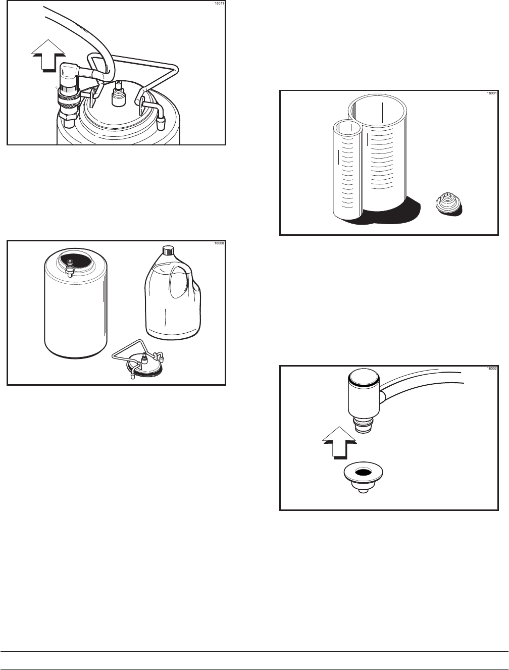
42 Model PH61Operating Procedures
Disconnect the syrup line after you have
disconnected the air line. (See Figure 62.)
Figure 62
Remove the syrup tank from the compartment.
Remove the syrup tank lid by lifting up on the locking
lever. Fill the syrup tank with syrup to the indicating
mark on the label. DO NOT overfill the tanks. (See
Figure 63.)
Figure 63
Replace the tank lid, match and connect the spiral
wrapped syrup line to the syrup tank. Connect the
air line to the syrup tank.
Repeat this procedure for all syrup tanks.
Step 2
Calibrating the syrup flow must be done on a daily
basis. It is vital that the correct amount of syrup be
incorporated into the mix to obtain a quality shake.
The cause of too thin shakes is often too much
syrup. The cause of too thick shakes is often too
little syrup.
To determine the rate of syrup flow, you will need a
syrup sampler and a calibration cup indicating fluid
ounces. The proper rate of syrup flow is 1 fl. oz. (30
ml.) of syrup in 5 seconds. Once this rate is set, the
correct amount of syrup will be blended with the
shake base regardless of the size of shake served.
(See Figure 64.)
Figure 64
Install the syrup sampler to the fitting on one of the
syrup lines. (See Figure 65.)
Figure 65
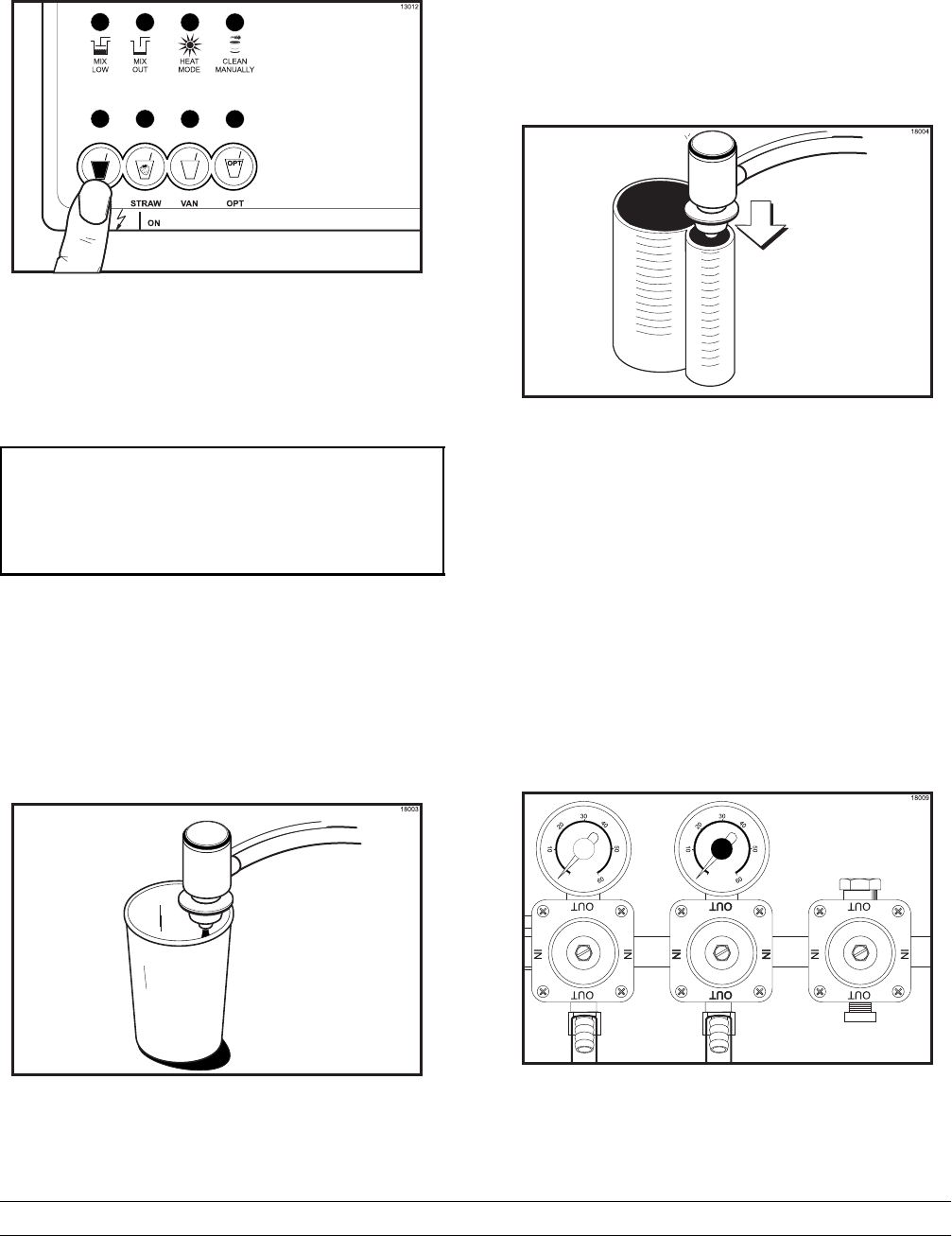
43
Model PH61 Operating Procedures
Push the corresponding flavor button for that syrup
flavor. (See Figure 66.)
Figure 66
Hold an empty courtesy cup beneath the exit point
of the syrup line. Press the CAL key (calibrate). A
message will appear on the LCD. (See Figure 67.)
SYRUP SYSTEM PRESS
AUTO - - - START CAL
WASH - - - CONTINUOUS
CAL - - - STOP
Figure 67
Press the WASH key. This will bleed any air pockets
from the syrup line.
When a STEADY stream of syrup is flowing into the
cup, press the CAL key to stop the syrup flow.
Discard the syrup in the cup. (See Figure 68.)
Figure 68
Hold the small portion of the calibrating cup under
the syrup line with the syrup sampler. Press the CAL
key. Press the AUTO key to check the rate of syrup
flow. After 5 seconds the flow of syrup will
automatically stop. If the amount of syrup received is
1 fl. oz. (30 ml.), the syrup is properly calibrated.
(See Figure 69.)
Figure 69
Step 3
Adjusting the syrup pressure: If the amount of
syrup is less than 1 fl. oz. (30 ml.) the syrup
pressure must be increased. If the amount of syrup
is more than 1 fl. oz. (30 ml.) the pressure must be
decreased.
Inside the syrup compartment is a regulator manifold
assembly with individual pressure regulators to
control the amount of pressure to each tank and
syrup line. (See Figure 70.)
Figure 70
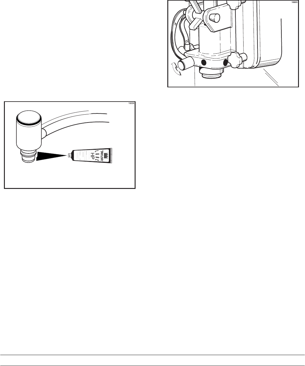
44 Model PH61Operating Procedures
If less than 1 fl. oz. (30 ml.) is received, the pressure
must be increased. Loosen the lock nut. Using a flat
blade screwdriver, turn the adjusting screw
CLOCKWISE.
Recheck the syrup calibration. Tighten the lock nut
after the correct calibration is achieved.
If more than 1 fl. oz. (30 ml.) is received, the
pressure must be decreased. Loosen the lock nut
and turn the adjusting screw
COUNTERCLOCKWISE to zero. Remove the air
line to the syrup tank to allow the pressure in the
tank to escape. Reconnect the air line. Adjust the
regulator to the new pressure setting and recheck
the syrup calibration. Tighten the lock nut.
Repeat the calibration procedures for each
additional syrup line.
Step 4
Remove the syrup sampler. Lightly lubricate the
o-ring on each syrup line fitting. (See Figure 71.)
Figure 71
Attach the syrup lines to the freezer door. Insert the
syrup line fitting into the syrup port in the freezer
door. The flat side of the syrup line fitting must be
aligned with the pin in the syrup port. Rotate the
syrup line fitting upward to lock in place. (See
Figure 72.)
Figure 72
Note: Whenever a particular syrup line is not used,
the syrup hole plug found in the spare parts kit must
be installed. Place the syrup hole plug o-ring into the
groove of the syrup hole plug and lubricate. Align the
flat portion of the syrup hole plug with the locking pin
in the open syrup port of the freezer door. Insert the
syrup hole plug and turn slightly to lock in place.
Step 5
Clean the calibration cup and syrup sampler.
This Procedure Must be Performed Weekly!
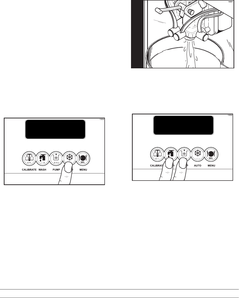
45
Model PH61 Operating Procedures
Closing Procedures
THIS PROCEDURE MUST BE COMPLETED
EVERY 14 DAYS.
FOLLOW YOUR LOCAL HEALTH CODES.
To disassemble the PH61, the following items will be
needed:
STwo cleaning and sanitizing pails
SNecessary brushes (provided with freezer)
SCleaning solution
SSanitizing solution
SClean, sanitized towels
SParts trays
Draining Product From the
Freezing Cylinder
Step 1
Cancel automatic operation by pressing the AUTO
key. (See Figure 73.)
Figure 73
Step 2
Remove the shake cup holder. Set it aside for
cleaning later with all parts.
Step 3
Remove the hopper cover and agitator. Take these
parts to the sink to wash, rinse and sanitize.
Step 4
With a pail under the door spout, press the WASH
and PUMP keys. Open the draw valve and start to
drain the product from the freezing cylinder and mix
hopper. (See Figure 74.)
Figure 74
Step 5
When the flow of product stops, press the WASH
and PUMP keys, cancelling the WASH and PUMP
modes, and close the draw valve. Discard this
product. (See Figure 75.)
Figure 75
Step 6
Remove the cotter pin, mix feed tube, pump clip and
the assembled air/mix pump. Place the parts into the
parts tray.
Step 7
Remove the syrup lines from the freezer door by
rotating the syrup line fittings and pulling out.
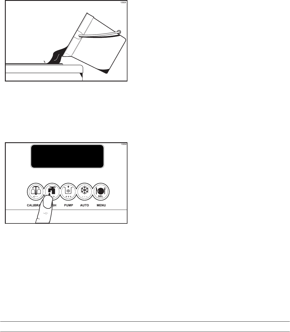
46 Model PH61Operating Procedures
080910
Rinsing
Step 1
Pour two gallons (7.6 liters) of cool, clean water into
the mix hopper. With the white hopper brush, scrub
the mix hopper, mix level sensing probes and the
outside of the agitator drive shaft housing. Using the
double ended brush, brush clean the mix inlet hole.
(See Figure 76.)
Figure 76
Note: Do not brush clean the mix inlet hole while
the machine is in the WASH mode.
Step 2
With a mix pail beneath the door spout, press the
WASH key. (See Figure 77.)
Figure 77
Step 3
Open the draw valve on the freezer door. Drain all
the rinse water from the door spout, close the draw
valve, and press the WASH key, cancelling the
wash cycle.
Step 4
Repeat this procedure using clean, warm water, until
the water being discharged is clear.
Cleaning and Sanitizing
Step 1
Prepare a pail of approved 100 PPM cleaning
solution (examples: 2-1/2 gal. [9.5 liters] of Kay-5R
or 2 gal. [7.6 liters] of Stera-SheenR). USE WARM
WATER AND FOLLOW THE MANUFACTURER'S
SPECIFICATIONS.
Step 2
Pour the cleaning solution into the hopper and allow
it to flow into the freezing cylinder.
Step 3
Using the white hopper brush, clean the mix hopper,
mix level sensing probes and the outside of the
agitator drive shaft housing. Using the double ended
brush, clean the mix inlet hole.
Note: Do not brush clean the mix inlet hole while
the machine is in the WASH mode.
Step 4
Press the WASH key. This will cause the cleaning
solution in the freezing cylinder to come in contact
with all areas of the freezing cylinder.
Step 5
Place an empty pail beneath the door spout.
Step 6
Open the draw valve on the freezer door and draw
off all the solution.
Step 7
Once the cleaning solution stops flowing from the
door spout, close the draw valve and press the
WASH key, cancelling the wash mode.
Step 8
Prepare a pail of approved 100 PPM sanitizing
solution (examples: 2-1/2 gal. [9.5 liters] of Kay-5R
or 2 gal. [7.6 liters] of Stera-SheenR). USE WARM
WATER AND FOLLOW THE MANUFACTURER'S
SPECIFICATIONS.
Step 9
Repeat steps 2 through 7 with the sanitizing
solution.
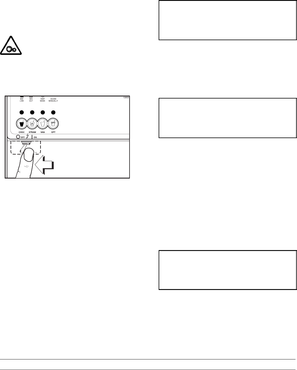
47
Model PH61 Operating Procedures
Disassembly
Note: Failure to remove the parts, brush clean, and
re-lubricate the parts, will result in damage to the
machine. These parts must be removed every 14
days or the machine will lock out and will not
operate.
Be sure the power switch is in the OFF
position. Failure to follow this instruction may result
in severe personal injury from hazardous moving
parts. (See Figure 78.)
Figure 78
In order for the control to recognize that the unit has
been brush cleaned, the following criteria must be
met.
SAll freezing cylinder and hopper
temperatures must be above 60_F(16_C).
SThe mix out and mix low probes must not be
satisfied.
SThe power switch must remain in the OFF
position for at least 5 minutes.
Note: These criteria must be met
simultaneously. These criteria will be met when the
unit is properly brush cleaned.
The following screen is displayed if the machine is
not in a brush clean state. (See Figure 79.) If any of
the requirements for a brush clean have not been
met, the time displayed will remain at 5:00 minutes.
POWER SWITCH OFF
OUT TIME: 4:40 OUT
68.5 HOPPER 62.1
69.5 BARREL 67.7
Figure 79
When all the requirements for a brush cleaning are
met, and the five minutes expire, the screen will
change to the second screen, which is the standard
power switch OFF screen. (See Figure 80.)
POWER SWITCH OFF
-=-=-=-=-=-
UNIT CLEANED
Figure 80
When the power switch is set in the ON position, the
system mode of operation screen is displayed. In
this example, the machine is ON, but no mode of
operation has been selected. The second line of the
display indicates whether there is a sufficient supply
of mix in the hopper or if there is a LOW or OUT mix
condition. The third line of the display shows the
temperature of the mix hopper. After pressing the
AUTO key, the last line of the display shows the
month and date (MM = month, DD = day) that the
machine needs to be disassembled and brush
cleaned. (See Figure 81.)
STANDBY :MODE: WSH-PMP
OUT :MIX: LOW
40.0F HOPPER 40.0F
BRUSH CLEAN ON: 10/31
Figure 81
Note: The Manual Clean LED will begin flashing 24
hours prior to a 14 day lock-out. The four mode
LED's will return to their normal function when the
unit is unlocked.
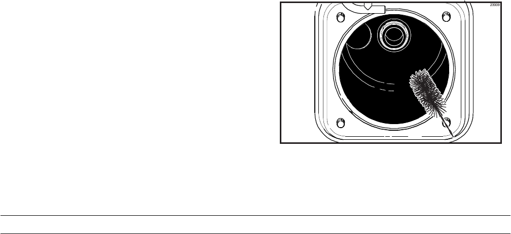
48 Model PH61Operating Procedures
With the parts tray available, remove the following
parts and place in the parts tray:
Step 1
Remove the syrup lines from the syrup ports, and
remove the restrictor cap from the bottom of the
door spout.
Step 2
Remove the spinner blade from the bottom of the
door spout by lifting up the locking collar on the
spinner coupling and pulling down the blade.
Step 3
Remove the handscrews, freezer door, beater
assembly with drive shaft seal and scraper blades
from the freezing cylinder.
Step 4
Remove the drive shaft seal from the drive shaft of
the beater assembly.
Step 5
Remove the freezer door o-ring, front bearing, pivot
pin, draw handle and draw valve spinner assembly.
Remove o-ring from pivot pin.
Step 6
Disassemble the draw valve spinner assembly.
Remove the driven spinner by grasping the draw
valve and pulling the driven spinner out. Remove the
spinner shaft seal.
Step 7
Remove the two o-rings from the draw valve.
Note: To remove o-rings, use a clean, sanitized
towel to grasp the o-ring. Apply pressure in an
upward direction until the o-ring pops out of its
groove. With the other hand, push the top of the
o-ring forward and it will roll out of the groove and
can easily be removed. If there is more than one
o-ring to be removed, always remove the rear o-ring
first. This will allow the o-ring to slide over the
forward o-rings without falling into the open grooves.
Step 8
From the pump cylinder, remove the retaining pin,
valve cap, piston, and the feed tube. Remove all
o-rings and the check ring.
Step 9
Remove the pump drive shaft from the drive hub in
the rear wall of the mix hopper.
Step 10
Remove the two small o-rings and one large o-ring
from the drive shaft.
Note: If the drip pans are filled with an excessive
amount of mix, it is an indication that the drive shaft
seal(s), or o-ring(s) should be replaced or properly
lubricated.
Brush Cleaning
Step 1
Prepare a sink with an approved 100 PPM cleaning
solution (examples: Kay-5® or Stera-Sheen®).
USE WARM WATER AND FOLLOW THE
MANUFACTURER'S SPECIFICATIONS.
Make sure all brushes provided with the freezer are
available for brush cleaning.
Step 2
Thoroughly brush clean all disassembled parts and
parts trays in the cleaning solution, making sure all
lubricant and mix film is removed. Be sure to brush
all surfaces and holes, especially holes in the pump
valve body and the small syrup holes in the freezer
door.
Step 3
Rinse all parts with clean, warm water, one tray at a
time, including the tray.
Step 4
Return to the freezer with a small amount of
cleaning solution. Using the black brush, clean the
rear shell bearing at the back of the freezing
cylinder. (See Figure 82.)
Figure 82
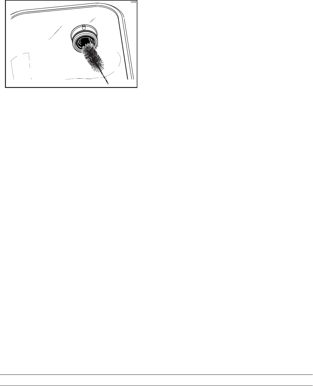
49
Model PH61 Operating Procedures
Step 5
Using the black brush, clean the drive hub opening
in the rear wall of the mix hopper. (See Figure 83.)
Figure 83
Step 6
Using the double end brush, brush clean the syrup
line fittings.
Step 7
Prepare a sink with an approved 100 PPM sanitizing
solution (examples: Kay-5® or Stera-Sheen®).
USE WARM WATER AND FOLLOW THE
MANUFACTURER'S SPECIFICATIONS.
Step 8
Repeat step 3 with the sanitizing solution.
Step 9
Sanitize all parts in the sanitizing solution for a
minimum of 1 minute.
Step 10
Place disassembled parts on clean and sanitized
parts trays.
Step 11
Wipe all exterior surfaces of the freezer with a clean,
sanitized towel.
Sanitizing the Syrup Systems
Two main objectives in your closing procedures
must be to:
1. Discard all syrup at least once a week.
2. Flush the syrup lines at least twice a week.
This must be done on a regular basis
a. to keep a build-up of old syrup from
clogging the lines, and
b. to break the bacteria chain which develops
in the tanks and lines.
Remember: Calibrating the syrup flow must be
done once every morning, especially after flushing
the syrup lines.
Step 1
Sanitizing the syrup tanks. Pull back on the collar
of the quick disconnect fitting of the air line. Allow
the air pressure to dissipate from the syrup tank.
Disconnect the syrup line.
Remove the syrup tank from its compartment.
Remove the syrup tank lid by lifting up on the locking
lever, and discard the remaining syrup.
Rinse the syrup tank with clean, warm water.
Prepare 1/2 gallon (1.9 liters) of the recommended
sanitizing solution with warm water in the syrup
tank. Brush clean the inside and outside of the tank.
Remove the syrup line fitting. Remove the dip tube
and o-ring from the syrup tank.
Thoroughly brush clean the dip tube, syrup line
fitting, and o-ring using the sanitizing solution.
Reassemble the dip tube, o-ring, and syrup line
fitting.
Pour off all the sanitizing solution and place the tank
in an upside-down position on a clean, dry surface to
air dry.
Repeat this procedure for all the syrup tanks.
Step 2
Sanitizing the syrup lines. Prepare one gallon (3.8
liters) of the recommended sanitizing solution with
warm water in the spare syrup tank. Replace and
lock the tank lid in position. Place this tank in the
syrup compartment.
Connect one of the air lines and the corresponding
syrup line to the syrup tank filled with sanitizing
solution.

50 Model PH61Operating Procedures
Place the power switch in the “ON” position. This will
activate the air compressor to supply pressure to the
syrup system.
Install the syrup sampler to the fitting of the syrup
line.
Press the corresponding flavor button for the syrup
line being sanitized.
Place an empty pail beneath the exit point of the
syrup line. Press the CAL key. A message will
appear on the LCD.
Press the WASH key. Flush the syrup line until the
solution runs clear. Press the CAL key to stop the
flow of sanitizing solution.
Note: This procedure will thoroughly clean the
syrup lines and prevent bacteria build-up.
Turn the syrup tank with the sanitizing solution
upside-down. Press the CAL key. Press the WASH
key to clear the syrup line of any remaining sanitizer.
When the sanitizer has been flushed from the syrup
lines, press the CAL key to complete this step.
Repeat this procedure for all syrup lines.
Place the power switch to the OFF position.

51
Model PH61 Important: Operator Checklist
070823
Section 7 Important: Operator Checklist
During Cleaning and Sanitizing
ALWAYS FOLLOW LOCAL HEALTH CODES.
Cleaning and sanitizing schedules are governed by
your State or local regulatory agencies and must be
followed accordingly. The following check points
should be stressed during the cleaning and
sanitizing operations.
CLEANING AND SANITIZING MUST BE
PERFORMED EVERY 14 DAYS.
Troubleshooting Bacterial Count:
j1. Thoroughly clean and sanitize machine
regularly, including complete disassembly and
brush cleaning.
j2. Use all brushes supplied for thorough
cleaning. The brushes are specially designed
to reach all mix passageways.
j3. Use the white bristle brush to clean the mix
inlet hole which extends from the mix hopper
down to the rear of the freezing cylinder.
j4. Use the black bristle brush to thoroughly
clean the rear shell bearing located at the rear
of the freezing cylinder and the drive hub
opening in the rear wall of the mix hopper. Be
sure to have a generous amount of cleaning
solution on the brush.
j5. Properly prepare the cleaning and sanitizing
solutions. Read and follow label directions
carefully. Too strong of a solution may
damage the parts and too weak of a solution
will not do an adequate job of cleaning or
sanitizing.
j6. Empty all syrup from the tanks and discard at
least once a week.
j7. Thoroughly clean and sanitize the syrup lines
at least once a week.
j8. Temperature of mix in mix hopper and walk-in
cooler should be below 40_F. (4.4_C.).
j9. Discard remaining mix from freezer during
“Closing Procedures”.
Regular Maintenance Checks:
j1. Rotate scraper blades to allow both sides of
the knife edge to wear evenly. This will
contribute to self-sharpening and help
maintain fast, efficient freezing.
j2. Replace scraper blades that are bent,
damaged, or worn down.
j3. Before installing beater, be certain that
scraper blades are properly attached over the
beater pins.
j4. Dispose of o-rings and seals if they are worn,
torn, or fit too loosely, and replace with new
ones.
j5. Check rear shell bearing for signs of wear
(excessive mix leakage in rear drip pan) and
be certain it is properly cleaned.
j6. Using a screwdriver and cloth towel, keep the
rear shell bearing and the female drive socket
free of lubricant and mix deposits.
j7. Follow all lubricating procedures as outlined in
“Assembly”.
j8. On air cooled units, check the condenser for
accumulation of dirt and lint. Dirty condensers
will reduce the efficiency and capacity of the
machine. Condensers and filters should be
cleaned monthly. Remove the rear panel to
gain access to the condenser. Use a soft
brush to clean between the fins of the
condenser. Never use screwdrivers or other
metal probes to clean between the fins.
j9. On water cooled units, check the water lines
for kinks or leaks. Kinks can occur when the
machine is moved back and forth for cleaning
or maintenance purposes. Deteriorated or
cracked water lines should be replaced only
by an authorized Taylor mechanic.

52 Model PH61Important: Operator Checklist
080910
Winter Storage
If the place of business is to be closed during the
winter months, it is important to protect the freezer
by following certain precautions, particularly if the
building is to be left unheated and subject to freezing
conditions.
Disconnect the freezer from the main power source
to prevent possible electrical damage.
On water cooled freezers, disconnect the water
supply. Use air pressure to blow out any water
remaining in the condensers. This is extremely
important. Failure to follow this procedure may
cause severe and costly damage to the refrigeration
system.
Your local Taylor Distributor can perform this service
for you.
Wrap detachable parts of the freezer such as beater
assembly and freezer door, and place in a protected,
dry place. Rubber trim parts and gaskets can be
protected by wrapping with moisture-proof paper. All
parts should be thoroughly cleaned of dried mix or
lubrication accumulations which attract mice and
other vermin.

53
Model PH61 Troubleshooting Guide
Section 8 Troubleshooting Guide
Problem Probable Cause Corrective Action
All four LED's are
flashing. The freezer is locked. See soft lock and hard lock information.
Soft lock message
appears on LCD. More than 24 hours since
the last HEAT cycle. The freezer must go through a HEAT cycle every 24
hours. The freezer must now be disassembled and
brush cleaned or placed in a heat cycle.
The power switch is in
the OFF position. The power switch must be in the ON position. The
freezer must now be disassembled and brush cleaned or
placed in a heat cycle.
The freezer is not in the
AUTO mode. The freezer must be in the AUTO mode. Freezer must
now be disassembled and brush cleaned or placed in a
heat cycle.
Mix out condition. The level of mix in the mix hopper must be above the
mix low probe. The freezer must now be disassembled
and brush cleaned or placed in a heat cycle.
The agitator is not
installed. The agitator must be cleaned and installed before
starting the HEAT cycle. The freezer must now be
disassembled and brush cleaned.
The agitator is not
rotating. The agitator must be cleaned before starting the HEAT
cycle. Disassemble the freezer and brush clean.
An equipment fault has
occurred. See Screen “H” in the Operator's Menu to determine the
cause.
Hard lock message
appears on the LCD. A barrel or hopper
thermistor is faulty. Call a service technician.
More than 14 days since
the last brush cleaning. The freezer must be disassembled and brush cleaned
every 14 days.
No product is being
dispensed. Low on mix. The MIX
OUT light is ON. Add mix to the mix hopper.
The power switch is in
the OFF position. Place the power switch to ON and press the AUTO key.
Freeze-up in mix inlet
hole. Call service technician.
Beater motor is out on
reset. Clear the tone. Allow the beater motor to cool. Place the
power switch to OFF. Press the reset button firmly,
place the power switch to ON and press the WASH key.
Open the side access panel and observe that the drive
shaft is turning CLOCKWISE as viewed from the front of
the machine. Press the AUTO key to return to the AUTO
mode. If the beater motor should go OFF on reset again,
call service technician.

54 Model PH61Troubleshooting Guide
Problem Corrective ActionProbable Cause
No product is being
dispensed. (Cont'd.) Air/mix pump is
incorrectly assembled or
improperly lubricated.
Follow assembly procedures carefully.
The mix pump ball crank
is broken. Call service technician.
The pump motor is not
activated. Push the reset button. The draw valve must be fully
opened to activate the pump motor.
The product is too thick. Not enough syrup - 1 fl.
oz. (30 ml.) in 5 seconds. Calibrate the syrups. Check that the syrup tanks have
an adequate syrup supply.
Insufficient mix in the
freezing cylinder. Check the air/mix pump assembly.
Improper priming
procedures. Drain the freezing cylinder and re-prime the machine.
Air/mix pump incorrectly
assembled. Follow assembly procedures carefully.
The viscosity control is
set too cold. Call service technician.
Freeze-up in mix inlet
hole. Call service technician.
Product is too soft. Too much syrup - 1 fl. oz.
(30 ml.) in 5 seconds. Calibrate syrups.
Outdrawing capacity of
freezing cylinder. Continuous draw rate is approximately one 16 oz. (473
ml.) shake by volume every 15-20 seconds.
Inadequate air space. Minimum of 6” (152 mm) air space around all sides.
Dirty condenser or air
filters on air cooled units. Clean regularly.
Inadequate water supply
on water cooled units. Check the water supply. Check the water lines for leaks
or kinks.
Bad scraper blades. Replace the scraper blades.
The viscosity control is
set too warm. Call service technician.
Air passage is blocked in
the pump. Brush clean the pump components and reassemble.

55
Model PH61 Troubleshooting Guide
Problem Corrective ActionProbable Cause
The mix in the hopper is
too warm. Hopper cover is not in
position. Clean the hopper cover and place in position.
The agitator is not
installed. Clean the agitator and install.
The hopper temperature
is out of adjustment. Call service technician.
The mix in hopper is too
cold. The hopper temperature
is out of adjustment. Call service technician.
Product is collecting on
top of draw valve. Inadequate lubrication of
spinner shaft or seal. Lubricate properly.
Spinner shaft seal is
missing or worn. Install or replace the spinner shaft seal.
Product is collecting on
top of the freezer door. The top o-ring on draw
valve is improperly
lubricated or worn.
Lubricate properly or replace the o-ring.
Excessive mix leakage
from the bottom of door
spout.
Bottom o-ring on draw
valve is improperly
lubricated or worn.
Lubricate properly or replace the o-ring.
Excessive mix leakage
into the long drip pan. The seal on drive shaft is
improperly lubricated or
worn.
Lubricate properly or replace the seal.
The seal is installed
inside-out on the drive
shaft.
Install correctly.
Worn or missing o-rings
on pump drive shaft. Install or replace the o-rings.
Inadequate lubrication of
the drive shaft. Lubricate properly.
The drive shaft and
beater assembly work
forward.
Call service technician.
Worn rear shell bearing. Call service technician.
Gear box out of
alignment. Call service technician.

56 Model PH61Troubleshooting Guide
Problem Corrective ActionProbable Cause
The drive shaft is stuck
in the drive coupling. Mix and lubricant
collected in drive
coupling.
Brush clean the rear shell bearing area regularly.
Rounded corners of drive
shaft, drive coupling or
both.
Call service technician.
Gear box is out of
alignment. Call service technician.
Freezing cylinder walls
scored. Missing or worn front
bearing. Install or replace the front bearing.
Broken beater pins. Repair or replace the beater assembly. When installing
scraper blades, be sure they are properly attached over
the pins.
Gear box is out of
alignment. Call service technician.
Spinner shaft will not
rotate to blend mix and
syrup.
Flexible coupling is
broken. Call service technician.
Pin is missing in quick
disconnect of spinner
coupling.
Call service technician.
Spinner motor is out on
thermal overload. Allow the spinner motor to cool. Also check lubrication
on spinner shaft. Properly align the motor and lubricate
properly.
Large adjustments are
necessary to receive 1 fl.
oz. (30 ml.) in 5 seconds.
Syrup lines are not
matched with correct
syrup flavor.
Match the color wrapped syrup lines to the correct syrup
flavors.
The plunger is sticking in
the syrup valve. Clean the valve.
Plugged syrup line fitting
at freezer door
connection.
Clean the syrup line fitting.
Verify that the proper
syrup selection was
made.
Make the proper syrup selection.
Pump will not operate in
the PUMP mode. Pump motor is not
activated. Push the reset button.
The membrane switch is
defective. Call service technician.

57
Model PH61 Troubleshooting Guide
Problem Corrective ActionProbable Cause
Machine will not run
when in the AUTO mode. Machine is unplugged. Plug into wall receptacle.
Beater motor is out on
reset. Clear the tone. Allow the beater motor to cool. Place the
power switch to OFF. Press the reset button firmly.
Place the power switch to ON, and press the WASH
key. Open the side access panel and observe that the
drive shaft is turning CLOCKWISE as viewed from the
front of the machine. Press the AUTO key to return to
the AUTO mode. If the beater motor should go OFF on
reset again, call service technician.
Circuit breaker OFF or
blown fuse. Turn the breaker ON or replace the fuse, and clear the
fault.
Low on mix. The MIX
OUT light is ON. Add mix to the mix hopper and press the AUTO key.
Water is turned OFF on
water cooled units. Turn water ON, and clear the fault.
Air compressor runs too
often for normal usage. Air leak in the system. Use a soap solution to locate the leak and repair.
Liquid Crystal Display is
blank. Machine is unplugged. Plug into wall receptacle.
Circuit breaker is OFF or
blown fuse. Turn the circuit breaker ON or replace the fuse, and
clear the fault.
Component failure. Call service technician.
LCD intensity needs
adjusting. Call service technician.
Product is not feeding
into the freezing cylinder. The mix inlet hole is
frozen up. The hopper temperature needs adjustment. Call service
technician.
The draw handle does
not close. Mix is on the sensing
eye. Clean the sensing eye.
Product “popping” when
drawn. Pump assembled
incorrectly. Assemble and lubricate according to instructions in this
manual.
Freezer shuts off, but
fault tone continues. Fault has occurred in the
freezer. Verify condition in the Operator's Menu “fault” screen.
Clear fault accordingly.
Inadequate air clearance
around the freezer. Minimum of 6” (152 mm) air space around all sides to
prevent recirculation of warm air.

58 Model PH61Troubleshooting Guide
Problem Corrective ActionProbable Cause
Syrup flows constantly,
or not at all. Difficult to
calibrate syrups.
Syrup lines are clogged. Disassemble and clean the syrup valves. Flush syrup
lines with warm water and sanitize weekly.
The syrup valve plunger
is stuck. Disassemble and clean the syrup valve.
Shakes have air bubbles
in them. Syrup valves are
clogged. Disassemble and clean the syrup valves.
Mix low and mix out
probes are not
functioning.
Milkstone build-up in the
hopper. Clean hoppers thoroughly.

59
Model PH61 Parts Replacement Schedule
Section 9 Parts Replacement Schedule
PART
DESCRIPTION EVERY
3MONTHS EVERY
6MONTHS ANNUALLY
Scraper Blade-Shake X
Drive Shaft Seal X
Freezer Door O-Ring-Shake X
Front Bearing X
Draw Valve O-Ring X
Spinner Shaft Seal-Shake X
Pivot Pin O-Ring X
Restrictor Cap-Shake X
Mix Feed Tube O-Ring X
Pump O-Ring X
Mix Inlet Tube O-Ring X
Mix Feed Tube Check Ring X
Air Inlet Fitting Seal X
Pump Drive Shaft O-Ring X
Pump Valve Gasket X
Brush A.-Package-HT-SS Inspect & Replace
if Necessary Minimum

Section 10 Parts List
60
Parts List Model PH61
080130
DESCRIPTION PART
NUMBER QTY. WARR.
CLASS REMARKS PARTS
UPDATE
ACCUMULATOR A.-AIR *5472*PRTL X46916 1103
+ FITTING A.-AIR ACCUM INLET X48548 1103 J5010000/UP 90
+ NIPPLE-1/8 MPT CLOSE BRASS 020519 1000
+ TUBE-VINYL 1/8 ID X 1/16 WALL 020938-6 1000 BULK UNDER P/N R30301
+ VALVE-SOLENOID-SERVICE 044125-27S 1103
ACCUMULATOR A.-GLYCOL (OLD) X41912 1103 J4019999/PRIOR (SEE TANK-GLYCOL) NLA 79
ACCUMULATOR-COPPER 2"DIA 10"LG 047062 1103 REFRIGERANT
ADAPTOR A.-CASTER X18915 4103
AGITATOR A. *HT*20 QT HOPPER X44797 1103
+ CAP-MAGNET *HT* 044796 1103
BEARING-DOOR-FRONT 1.390 OD 055605 1000
BEARING-REAR SHELL *NICK.PLATE 031324 1000
+ GUIDE-DRIP SEAL 028992 1000
+ NUT-BRASS BEARING 028991 1000
+ O-RING-1/2OD X .070W 024278 2000
+ WASHER-BEARING LOCK 012864 1000
BEATER A.-7QT-FLUTED BLADE X50958 1103 REPLACES X42315 USE W/050985 BEATER SHAFT 113
+ BLADE-SCRAPER-FCB-PRESSURE-16" 041103 2000
BELT-RD 3/16 GREEN 062191-4 1000
BELT-V-4L400 007590 1000
BLADE A.-SPINNER-ALUMINUM-HT X41895 1103
BLOCK-TERMINAL 3P 039423 2103
BLOCK-TERMINAL 3P .25 SPADE 057201 1103
BLOCK-TERMINAL-PLUG 10P .2 SIP 040322-005 1103 J14 IB
BLOCK-TERMINAL-PLUG 6P .2 SIP 040322-002 2103 J5 IB
BLOCK-TERMINAL-PLUG 7P .2 SIP 040322-003 2103 J7 & J6 IB
BLOCK-TERMINAL-PLUG 8P .2 SIP 040322-004 2103 J10 IB
BOTTLE A.-SQUEEZE *5472* X45080 1000
O-RING-1/2OD X .070W 024278 1000
BRUSH A.-PACKAGE-HT X44127 1000
CABINET A.-SYRUP *5472* X45769 1103
CABLE-RIBBON-10C-34"L-DIL/DIL 040040-023 1103 J3 IB TO LED
CABLE-RIBBON-10C-5"L-DIL/DIL 040040-024 1103 LED TO LED

61
Model PH61 Parts List
DESCRIPTION PARTS
UPDATE
REMARKSWARR.
CLASS
QTY.PART
NUMBER
CABLE-RIBBON-14C-22"L-SIP/SIP 040040-019 1103 J9UC TO LCD
CABLE-RIBBON-20C-33"L-DIL/DILR 040040-027 1103 J12IBTOJ2UC
CABLE-RIBBON-20C-35"L-DIL/DIL 040040-026 1103 J9 IB TO J7 UC
CABLE-RIBBON-50C-25"L.DIL/DIL 040040-025 1103 J2 IB TO J10 UC
CABLE-4 COND-#22 SHIELDED 039309-28 1103 POWER CABLE IB-UC (BULK P/N R6003003)
CAP A.-VALVE-DRAW-INSULATED X54704 1103
CAP-RESTRICTOR 033107 1000
CAPACITOR-RUN- .8UF/400V 039482 1103 AGITATOR MOTOR
CAPACITOR-RUN 10UF/370V 033047 1103 SPINNER MOTOR
CAPACITOR-RUN 4UF/440V 051785 1103 FAN MOTOR & AGITATOR MOTOR
CARD-DAILY CLEAN-HT-SHK-PUMP 046702 1000
CASTER-SWV 5/8 STEM 4IN WHEEL 018794 4103
CLAMP-HOSE 9/16 CRIMP TYPE 047344 14 000 GLYCOL HOSE
COLLAR-HOLDING 019481 2103 CUP DISPENSER
+ SCREW 001086 2000
COMPRESSOR M63B203DBDB 062274-33 1512 208-230V 60HZ 3PH - K6050000 & UP - BRISTOL
+GROMMET-COMPRESSOR MOUNTING 037428 4000
+SLEEVE-MOUNTING-COMP. 039924 4000
COMPRESSOR AH7513Z-AH245RT 047520- 1512 J4048006-K6040000 HP62 (-F = FRENCH BUILT
J909000/ UP)
80
+ GROMMET-COMPRESSOR MOUNT-AH 039923 4000 J4048006/UP HP62 80
+ SLEEVE-MOUNTING-COMP.-AH 039924 4000 J4048006/UP HP62 80
COMPRESSOR M51B143DBLA 036880- 1512 J4048005/PRIOR 80
+ GROMMET-COMPRESSOR MOUNTING 037428 4000 J4048005/PRIOR 80
+ SLEEVE-MOUNTING-COMP. 039924 4000 J4048005/PRIOR 80
COMPRESSOR-AIR-230V SERV 032129SER2 1103
+ CROSS-1/4 FPT 077339 1000
+ FITTING-1/4MPT X .170BARB STR 075880 1103
+ GAUGE-PRESSURE 0-60 PSI 1/4MPT 046933 1103
+ NIPPLE-1/4IPT X 7/8LONG BRASS 026496 1103
+ SWITCH-PRESSURE-240V, 3HP 063944-C 1103
+ VALVE-CHECK 1/4MP 020959 1103
CONDENSER-AC-12LX18HX4.3-5ROW 019558 1103
CONTROL-ROHS-LED-4 POSITION 063930 2212

62
Parts List Model PH61
DESCRIPTION PARTS
UPDATE
REMARKSWARR.
CLASS
QTY.PART
NUMBER
COUPLING A.-DRIVE-SPINNER X20329 1103
PIN-ROLL-.094D X .562L 015971 1000
COUPLING A.-TORQUE-SHAKE*GOLD* X54722-GLD 103 REPLACES X52620
COUPLING-TORQUE-DRIVE TTS 054723 1103
COUPLING-TORQUE-LOAD-SQ *TTS 054724 1103
PIN-COUPLING-TORQUE 039453 4103
PIN-STOP-TORQUE COUPLING .79 054725 4103
SCREW-5/16-18X3/8 SOCKET SET 025376 2000
SCREW-SHOULDER 8-32X3/16 SLT 039455 4000
SPRING-3/8ODX3/16IDX1L-GOLD 052476 4103
COUPLING-FLEXIBLE W/SCREWS 020108 1103
COVER A.-HOPPER INS.-COMPLETE X65369 1103
LABEL-CAUTION-AGITATOR 045191 1000
+ PIN-RETAINING-HOPPER COVER 043934 4103
CUP-DIVIDED SYRUP 017203 1000
CYLINDER-AIR 1-1/6 BORE X 1 IN 032999 1103 DRAW HANDLE SHUT OFF
+ CAP-AIR CYLINDER *PORTION CTRL 045975 1103
+ SCREW-8-32 X 1/4 ALLEN SET 043603 1000
DECAL-DEC-TAYLOR-PH61 (NEW) 052280 1000 J8120000/UP - "ON POSITION ON RIGHT SIDE" 137
DECAL-MAG-CLOSING CHECKLIST 044309 1000
DECAL-INST-CLN-DAY-HT-SHK 045271 1000
DECAL-INST-CLN-HT-SHK 045274 1000
DECAL-SET 4 SYRUP FLAVOR 021523 1000
DECAL-SET-SYRUP VALVES 045521 1000
DECAL-SYRUP COMPARTMENT 021571 1000
DECAL-SYRUP FLAVOR INSTRUCTION 020997 1000
DECAL-TROUBLESHOOTING 038374 1000
DIAGRAM-WIRING 044816-33 1000 208-230V 60HZ 3PH - 3 WIRE
DISPLAY-LIQUID CRYSTAL X38062-SER 1103
+ LENS-DISPLAY 038221 1103
+ STANDOFF-LENS 038225 4000 048901
+ SCREW-2-56 X 1/2 038219 4000
+ NUT-HEX 038220 4000

63
Model PH61 Parts List
081110
DESCRIPTION PARTS
UPDATE
REMARKSWARR.
CLASS
QTY.PART
NUMBER
DOOR A.-1 SPT-4 FLV-HT X55724-SER 1512
HANDLE-DRAW VALVE *8663* 034003 1103
PIN A.-PIVOT X22820 1103
O-RING-5/16 OD X .070W 016272 1000
SEAL-SPINNER SHAFT 036053 1000
SPINNER *8663* 034054 1103
VALVE A.-DRAW-ALUMINUM *5472 X42210 1103
O-RING-1-1/16 OD X.139W 020571 2000
DOOR A.-SYRUP CABINET *5472* X45325 1103
+ BEARING-SYRUP CAB. DOOR *5472* 045339 2000 WHITE PLASTIC
+ BUSHING-SYRUP CAB. DOOR *5472* 045340 2000 METAL INSERT
+ NUT-10-32-1/2 005598 2000
+ PLATE-HINGE *5472*LOWER 045338 1103
+ PLATE-HINGE *5472*UPPER 045337 1103
+ SCREW-10-32X3/4 033944 2000
DRYER-FILTER-HP62-3/8 X 1/4S 048901 1000
DVD-OPS TRAINING VIDEO *PH61 049663-DVD 1000
FASTENER-CLIP 1/4-20 U-TYPE 045865 10 000
FILTER-CORCOM 6EH1 040140-001 1103
FILTER-INLINE-GLYCOL-40 MICRON 041670 1103
+ ARMAFLEX-BOOT USE 047490-4.5 047490-4.5 1000
FLUID A.-HEAT TRANSFER X39667 1000
FUSE-15 AMP-IN LINE-NON DELAY 045293 1000 045606 HOLDER
GASKET-SYRUP DOOR 045326 1000
GEAR A.*REDUCER 4.21:1 SERVICE 021286-SER 1212
GEAR A.*REDUCER-AGITATOR 047988 1103
GUARD-POWER SWITCH 034830 1103
GUIDE A.-DRIP PAN *5472* X45386 1103 FRONT PANEL-REAR SHELL BEARING
GUIDE A.-DRIP PAN-MIX PUMP X48228 1103 REAR PANEL-MIX PUMP J4070000/UP 84
HEATER A.-GLYCOL-2500W *H60* X47331S27G 1103
THERMOSTAT-HI LIMIT OPEN 200 035786 1103
HOLDER A.-SENSOR-ADJ/15 DEGREE X54617 1103 REPLACES X38976
BRACKET A.-SENSOR X51465 2103

64
Parts List Model PH61
DESCRIPTION PARTS
UPDATE
REMARKSWARR.
CLASS
QTY.PART
NUMBER
HOLDER-SENSOR-PYROELECT 15 DEG 063747 1103
NUT-5/16-18 SPECIAL HEX NUT 043072 1000
PIN-GUIDE-5/16OD X 1-5/16LG 038980 2103
SCREW-10-32X9/16 SOCKET SET 038981 1000
SCREW-8X3/8 SLTD PAN B SMS 035647 2000
SCREW-ADJUSTMENT-5/16-18 051574 1000
HOLDER-CUP-SHAKE 046939 1103 88
+ CLIP-SPRING-CUP HOLDER 046940 2103 88
HOLDER-FUSE-IN LINE-TYPE HLR 045606 1103 045293 FUSE
HOSE-RUBBER 5/16"ID X 9/16"OD 047340- 7FT 000 BULK UNDER R502011 (GLYCOL)
HOUSING A.-AGITATOR *HT* X51664 1103
MAGNET A.-AGITATOR-INNER X41733 1103
SCREW-8-32 X 3/16 ALLEN SET 006812 2000
KIT A.-BRUSH-HT X44127 1000
BRUSH-1/2" DIA 033059 1000
BRUSH-DOUBLE ENDED-PUMP&FEED T 013072 1000
BRUSH-DRAW VALVE 1"ODX2"X17"L 013073 1000
BRUSH-DRAW VALVE 1-1/2"OD X 3" 014753 1000
BRUSH-END-DOOR-SPOUT-SS-HT 039719 1000
BRUSH-MIX PUMP BODY-3"X7"WHITE 023316 1000
BRUSH-PUMP SPOUT *MC13* 054068 1000
BRUSH-REAR BRG 1IN.DX2IN.LGX14 013071 1000
BRUSH-SET LVB 050103 1000 Includes 045079 Syrup Port Brush
BRUSH-SYRUP PORT 045079 1000
KIT A.-TUNE UP 5472 SIMPL PUMP X49463-63 1000
KIT A.-DRAW VALVE *SHAKE* X56200-1 1000
CAP-RESTRICTOR 033107 1000
O-RING-1-1/16 OD X.139W 020571 2000
O-RING-5/16 OD X .070W 016272 1000
SEAL-SPINNER SHAFT 036053 1000
KIT A.-PUMP-SIMPLIFIED SS/SH X56200-10 1000
GASKET-SIMPLIFIED PUMP VALVE 053527 1000
O-RING 1/2 ID X .139W 048632 2000

65
Model PH61 Parts List
DESCRIPTION PARTS
UPDATE
REMARKSWARR.
CLASS
QTY.PART
NUMBER
O-RING-11/16ODX.103W-RED 016132 2000
O-RING-1-3/4 OD X .139W 008904 1000
O-RING-2-1/8 OD X .139W-#225 020051 2000
RING-CHECK-FEED-TUBE 056524 1000
KIT A.-DOOR/BARREL*SHAKE*863 X56200-4 1000
KIT A.-BEARING 055605 X56091 1000
O-RING-1/2OD X .070W 024278 4000
O-RING-1-11/16 OD X.139W 041923 1000
O-RING-11MM ID X 2MM W GREEN 053890 4000
O-RING-6 IN ODX5 3/4 IDX 1/8 033493 1000
SEAL-DRIVE SHAFT 032560 1000
KIT A.-SYRUP VALVE-HOFFMAN X56200-7 1000
O-RING-1/2OD X .070W 024278 4000
TOOL-O-RING REMOVAL-FREEZER 048260-WHT 1000
LABEL-1/4 X 1-1/2 LONG-BROWN 022710 1000
LABEL-1/4 X 1-1/2 LONG-DK BLUE 022708 1000
LABEL-1/4 X 1-1/2 LONG-RED 022707 1000
LABEL-1/4 X 1-1/2 LONG-WHITE 022709 1000
LABEL-CAUTION-AGITATOR 045191 1000
LABEL-CAUTION-GROUND-ENG/SPN 032164 1000
LABEL-DOOR-WARN-MOVE PART 032749 1000
LABEL-WARN-COVER 051433 6000
LINE A.-AIR 45 DEG BARB X47043-12 4103 FROM AIR MANIFOLD TO SYRUP TANKS
ELBOW-1/4MPT X 1/4BARB-45 DEG. 046925 4103
FERRULE-.475 ID NP BRASS 021082 8000
SOCKET-Q.D. CO2 90DEG 1/4BARB 021524 4103
TUBE-NYLOBRADE 1/4ID X 7/16OD 020568-12 4000
LINE A.-SYRUP-TWIN TUBE X53399-88 4103 145
FERRULE-.462 ID NP BRASS 053888 4000
FITTING-SYRUP VALVE 053397 4103
O-RING-1/2OD X .070W 024278 4000
TUBE-TWINNED 84" 045359 4000
CLAMP-TWIN TUBE 052079 8000

66
Parts List Model PH61
DESCRIPTION PARTS
UPDATE
REMARKSWARR.
CLASS
QTY.PART
NUMBER
LIP-DRIP-NOSE CONE 036435 1000
LUBRICANT-TAYLOR HI PERFORMANCE 048232 1000
MAN-OPER PH61 048119-M 1000 J4063652/UP 82
MANIFOLD A.-REGULATOR *5472* X46924 1103
DECAL-FLAVOR COLOR SET '4' 022105 1000
FITTING 1/4 X .170 90 DEGREE 075946 1000
GAUGE-PRESSURE 0-60 PSI 1/8MPT 027875 4103
NIPPLE-1/4IPT X 7/8LONG BRASS 026496 2000
PLUG-1/4MP BRASS 027747 2000
REGULATOR-PRESSURE-CO2 027744 5103
VALVE-PRESSURE RELIEF-45# 047252 1103 J3110000/UP 76
MANIFOLD-FIVE VALVE-90 DEG. 046920 1103 J3070000 - J6061311 (X50644 UPDATE KIT) 73 & 107
MANIFOLD-FIVE VALVE 045787 1103 J2111806 - J3069999 (X50644 UPDATE KIT) 63 & 73
MANIFOLD-FOUR VALVE 037780 1103 PRIOR TO J2111806 N/A 63
VALVE-AIR-3 WAY-24VAC 045787-1 4103 PRIOR TO J6061311
VALVE-AIR-3 WAY-12VDC 045787-2 1103 PRIOR TO J6061311
MOTORA.-SPINNERW/PLUG X35584SER2 1103
CONNECTOR-PLUG 3 PIN FEMALE 022522 1103
PIN-MALE .084"DIA-MATE-N-LOK 021624 3103
+CAP-CYLINDER-AIR-PORTION CTR 045975 1103
+CYLINDER-AIR 1-1/6 BORE X 1 032999 1103
MOTOR-1.0 HP 013102-33 1212
MOTOR-AGITATOR 047987-27 1103
MOTOR-FAN 80 WATT 1550 RPM C 051744-27 1103
+CONNECTOR-MATE LOCK 4 CIR-PI 500534 1103
+PIN-.084 OD/14-20 AWG-STRIP 021624 3103
+FAN-5 BLADE 12" PUSH 26DEG CCW 029771 1103
MOTOR-REDUCER-SERVICE 044723-27S 1103 60Hz
+ GEAR-ONLY 049243-27 2103 60Hz 93
+ MOTOR-ONLY 049242-27 2103 60Hz 93
+ SEAL-MOTOR REDUCER-INPUT SHAFT 048836 2000 90
+ SEAL-MOTOR REDUCER-OUTPUT SHAFT 048837 2000 90
NUT-STUD *482-5472-8663-8634* 034034 4103 (HANDSCREW)

67
Model PH61 Parts List
DESCRIPTION PARTS
UPDATE
REMARKSWARR.
CLASS
QTY.PART
NUMBER
NYLON-SPIRAL WRAP-BLUE-2" 041582-4 2000 BULK UNDER P/N R40336
NYLON-SPIRAL WRAP-BROWN-2" 041582-1 2000 BULK UNDER P/N R40338
NYLON-SPIRAL WRAP-RED-2" 041582-2 2000 BULK UNDER P/N R40337
NYLON-SPIRAL WRAP-WHITE-2" 041582-3 2000 BULK UNDER P/N R40320
O-RING SILICONE-RED (SYRUP VALVE FITTING) 053398-RED 1000 J9096706/UP (REPLACES 042503-RED SHROUD) 145/146
O-RING SILICONE-BLU (SYRUP VALVE FITTING) 053398-BLU 1000 J9096706/UP (REPLACES 042503-BLU SHROUD) 145/146
O-RING SILICONE-WHT (SYRUP VALVE FITTING) 053398-WHT 1000 J9096706/UP (REPLACES 042503-WHT SHROUD) 145/146
O-RING SILICONE-BRN (SYRUP VALVE FITTING) 053398-BRN 1000 J9096706/UP (REPLACES 042503-BRN SHROUD) 145/146
OVERLOAD-TI#2BM-KG-16-68 042005-34 1103 MOTOR REDUCER 50 &60 Hz
+ NUT-OVERLOAD RESET 045026 1000
PAIL-MIX 10 QT. 013163 1000
PAN A.-DRIP *5459* X28142 1103
PAN-DRIP HT 048204 1103 J4070000/UP MIX PUMP 84
PANEL A.-FRONT *PH61* X55436 1103
PANEL A.-LOWER SIDE X24397-SER 1103 LEFT
PANEL-LOWER SIDE R.*5472/PH61 034680 1103 RIGHT
PANEL-REAR *5472* 048203 1103
PANEL-SIDE-UPPER-LEFT *5472* 056012 1103
PANEL-SIDE-UPPER-RIGHT *5472* 056013 1103
PCB A.-CONTROL *PH61* UVC2 X52547-SER 1212 134/135
CHIP-SOFTWARE PH61 CTRL UVC2 X40881 1103
PCB A.-UVC2 X51169-SER 1212 BASEBOARD
PCB A.-INTERFACE-HT-SH-UK X53452-SER 1212
PCB A.-PERSONALITY-HT-SH X44748-SER 1212
PCB A.-HEAT TREAT INTF BASE-UK X53451-SER 1212
PLATE A.-DEC-5472* X45356 1NNN
PLUG-Q.D. CO2 1/8 MP 021077 4103 SYRUP TANK
PLUG-Q.D. LIQ. 3/4-18 FP 021081 4103 SYRUP TANK
+ INSERT-QD PLUG 021081-1 4103 FORQDPLUG
+O-RING 016030 4103 FORQDPLUG
PLUG-SYRUP HOLE 026278 4000
PROBEA.-MIXLOW-HT X42077 1103 MIX LOW
+ DISC-PROBE *SQ HOLE* 030965 1103

68
Parts List Model PH61
DESCRIPTION PARTS
UPDATE
REMARKSWARR.
CLASS
QTY.PART
NUMBER
+ SPACER-PROBE *SQ HOLE* 030966 1103
PROBEA.-MIXOUT-SQUAREHOLE X41348 1103 MIX OUT
+ SPACER-PROBE-SQUARE HOLE-7/8 041346 1103
+ SPACER-PROBE-ROUND HOLE-5/8DIA 041347 1103
PROBE-THERMISTOR-BARREL-2% TOL 038061-BLK 1103 BARREL
PROBE-THERMISTOR-HOPPER-2% TOL 039470-BLK 2103 HOPPER
PULLEY-AGT DR-1.910PDX5/16 THD 036210 1103 AGITATOR MOTOR
+ SCREW-8-32 X 1/4 ALLEN SET 043603 1000
PULLEY-AW62-5/8 007538 1103 GEAR
PULLEY-AK25-5/8 019153 1103 BEATER MOTOR
PUMP A.-MIX SIMPLIFIED SHAKE X57028-14 1103
ADAPTOR-MIX INLET-SHK-BLUE 054944 1103
CAP-VALVE BODY SHAKE 056873-14 1103
CYLINDER-PUMP HOPPER SHAKE 057944 1103
GASKET-SIMPLIFIED PUMP VALVE 053527 1000
O-RING-2-1/8 OD X .139W-#225 020051 2000
PIN A.-RETAINING X55450 1103
PISTON-PUMP-SIMPLIFIED 053526 1103
PUMP-GLYCOL-1/8NPT-1650 RPM 041785 1103
MOTOR-SERVICE-GLYCOL PUMP 041785-1 1103
PUMP-SERVICE-GLYCOL PUMP 041785-2 1103
MAGNET-GLYCOL PUMP MOTOR 041785-3 1103
+ BOOT-GLYCOL PUMP 042131 1000
RELAY-3 POLE-20A-208/240 50/60 012725-33 1103 MAIN COMPRESSOR
RELAY-MTR START TI#4CR-2-645 042007-34 1103 MOTOR REDUCER 50 & 60Hz
RELAY-SPDT-30 A-240 V 032607-27 1103 GLYCOL HEATER
RESTRICTOR-SYRUP 025816 4000
SAMPLER-SYRUP 045031 1000
SANITZER- KAY-5 125 PCKTS 041082 1000
SENSOR A.-EVC-SHAKE-33" X42658 1103
SENSOR A.-PYROELECTRIC-24"L X42656 1103
SHIELD-PYROELECTRIC SENSOR 039096 1103
SHAFT A.-DRIVE-MIX PUMP-HOPPER X41947 1103

69
Model PH61 Parts List
DESCRIPTION PARTS
UPDATE
REMARKSWARR.
CLASS
QTY.PART
NUMBER
CRANK-DRIVE-HOPPER MIX PUMP 039235 1103
O-RING 1/2 ID X .139W-206 048632 2000
O-RING-1-3/4 OD X .139W 008904 1000
SHAFT-DRIVE-MIX PUMP-HOPPER 041948 1103
SHAFT-BEATER *7QT FLUTED* 050985 1103 USE W/ X50958 BEATER
+ SEAL-DRIVE SHAFT 032560 1000
SHELL A.-INSULATED *5472*HOOD X45362-SER 1512
STUD-FREEZER *8663* 034035 4103
+NUT-STUD *482-5472-8663-8634 034034 4103
SHIELD-SPLASH 15"L X 5-13/32"W 022763 1103
SLEEVE A.-MIX PUMP *HT*MCD X44761 1103
+ NUT-PUMP SLEEVE *8751*HT* 036933 1103
SOCKET-Q.D. LIQ.-90DEG-1/4BARB 021026 4103
STARTER-3 PHASE-3 TO 5 AMP 041950-33J 1103 97
OVERLOAD-THERMAL 047150-33J 1103 101
SWITCH A.-DRAW *5472* X45076-SER 1103
BEARING-SWITCH *482-8663* 034042 1000
BEARING-SWITCH *482-8663* 034043 2000
BRACKET A.-ACTUATOR *5472 HT* X41882 1103
BRACKET A.-DRAW SWITCH *5472HT X41879 1103
E-RING 1/4 032190 1000
INSULATOR-SWITCH 1/64 ARMITE 029099 1000
NUT-PUSH ON-1/2DIA. SHAFT 039735 2103
ROD A.-DRAW *5472 HT* X41880 1103
SWITCH-LEVER-SPDT-15A-125-250V 027214 1103
SWITCH-MEMBRANE-5 POSITION-8"L 044520 2103 KEYPAD
+ PLATE-BACK UP-MEMBRANE SWITCH 044578 2103
SWITCH-PRESSURE 440 PSI-SOLDER 048230 1103 105
SWITCH-PRESSURE-240V, 3HP 063944-C 1103
SWITCH-TOGGLE-DPDT*ON-NONE-ON 024295 1103
TANK-GLYCOL 1.5QT-PLASTIC 047314 1103 J4020000/UP 79
CAP-GLYCOL TANK 047314-1 1103 J4020000/UP 79
TANK-SYR-4 QT 045533 4103

70
Parts List Model PH61
DESCRIPTION PARTS
UPDATE
REMARKSWARR.
CLASS
QTY.PART
NUMBER
COVER-SYRUP TANK W/INLET FITTING 035759-1 4103 INCLUDED W/TANK
GASKET 016037 4000
+ DECAL-SYRUP TANK INSTRUCTION 045533-1 4000
TIP-NYLON-WHITE 042747 8000
TUBE-DIP 015441-7 4103
O-RING 018550 4000
TEE-ACCESS-5/16 HOSE W/5344COR 047587 1000
TOOL-COAX PUMP-LVB&DRIVE SHAFT 047919 1000
TOOL-SEAL INSTALL-REMOVE 035460 1000
TOOL-SHAFT-DRIVE-PUMP-HOPPER 057167 1000
TRANS.-240V PR1/24V SEC 10 VA 030132-27 1103 SYRUP CONTROL
TRANS.-CONT.-40VA 120/200/240V 045754 1103 INTERFACE BOARD
TRAY-DRIP 14-7/8L X 5-1/8 SGL 013690 1103
TRAY-PARTS-BARREL 044118 1000 118
TRAY-PARTS-PUMP-SIMPLIFIED 056525 1000
TRIM-REAR CORNER-LEFT 045516 1103 LEFT 123
TRIM-REAR CORNER-RIGHT 045517 1103 RIGHT 123
NUTSERT-10-32 047597 4103 FOR REAR CORNER TRIM 123
TRIM A.-SHELF *5472* X45334 1103 BELOW SPLASH SHIELD
TUBE A.-FEED-HOPPER-SHAKE X56522 1103
TUBE-.170 ID X .250 OD 075885- 115 ft 000 BULK UNDER P/N R40302
TUBE-VINYL 1/4ID X 1/16WALL 020941-16 2000 BULK UNDER P/N R30312
TUBE-VINYL 1/8ID X 1/16 WALL 020938-17 4000 BULK UNDER P/N R30301 (SYRUP MANIFOLD)
VALVE A.-SYRUP CONTROL *5472* X58145 1103
BRACKET A.-QEV MOUNT *5472* X56790 1103
DECAL-SET-SYRUP VALVES 045521 1000
FITTING-ELBOW SYRUP MANIFOLD 050492 2103
FITTING-BARB SYRUP MANIFOLD 050493 1103
VALVE-SYRUP 5 BLOCK-QEV-TRAP 056494 1103
VALVE-ACCESS 1/4FL X 3/8SOLDER (LOW SIDE) 043232 1103
VALVE-ACCESS-1/4 MFLX1/4 S-90 (HIGH SIDE) 047016 1103 80
VALVE-EXP-AUTO-1/4S X1/4 FPT 046365 1103 80
WASHER-PLASTIC PIVOT 013808 2000 SWING PANEL

71
Model PH61 Parts List
DESCRIPTION PARTS
UPDATE
REMARKSWARR.
CLASS
QTY.PART
NUMBER
WATER COOLED
ADAPTOR-3/8MP X 1/2BARB-BR 011021 2103
BLOWER-100CFM 012796-27 1103 208-230V 60HZ 3PH
BRACKET-MOUNTING-WATER VALVE 038777 1103
+SCREW-8-32X5/16 PHIL PAN EXT. 038778 2000
CONDENSER-W/C-COAX 047540 1103 80
+ELBOW-5/8S X 1/2S SHORT RADIUS 017303 2103
+ELBOW-1/2OD COPPER X 1/2 HOSE 034095 2103
CLAMP-HOSE-ADJ 7/16 X 25/32 010031 4000
GUARD-BLOWER 022505 1103
HOSE-RUBBER-1/2" ID X 7/8" OD R50200 4ft 000
MANIFOLD-1/2S THRU-1/4S OUT-3 046688 1103
SWITCH-PRESSURE 350 PS1-SOLDER 048231 1103 105
SWITCH-PRESSURE-240V, 3HP 063944-C 1103
VALVE-WATER 3/8 REG/HEAD 046686 1103 80
50Hz
BLOCK-TERMINAL 7P GREEN 024156 2103 220-240V 50HZ 3PH - 200V 50/60HZ 3PH -
BLOCK-TERMINAL 7P GREEN 024156 1103 380-415V 50HZ 3N~ (4WIRE)
BLOCK-TERMINAL 4P L1,L2,L3,N 039424 1103 380-415V 50HZ 3N~ (4WIRE)
COMPRESSOR M63B203DBDB 062274-33 1512 220-240V 50HZ 3PH
COMPRESSOR M63B203DBEB 062274-58 1512 380-415V 50HZ 3N~ (4WIRE)
DIAGRAM-WIRING *PH61* 044816-35 1NNN 220-240V 50HZ 3PH
DIAGRAM-WIRING *5472* 044816-39 1NNN 200V 50/60HZ 3PH
DIAGRAM-WIRING *5472*UNIVERSAL 044816-62 1NNN 380-415V 50HZ 3N~ (4WIRE)
DVD-OPS TRAINING VIDEO *PH61* 049663-DVD 1000
HARNESS-WIRE 5472 COMP. W/GRND 056889-G 1NNN 220-240V 50HZ 3PH - 200V 50/60HZ 3PH - 380-415V
50HZ 3N~ (4WIRE)
HARNESS-WIRE 5472 COND FAN MTR 056893-G 1NNN 220-240V 50HZ 3PH - 380-415V 50HZ 3N~ (4WIRE)
HARNESS-WIRE-BTR MTR H60-H63 056890-G 1NNN 220-240V 50HZ 3PH - 200V 50/60HZ 3PH - 380-415V
50HZ 3N~ (4WIRE)
HARNESS-WIRE 5472 AGITATOR MTR 056891-G 1NNN 220-240V 50HZ 3PH - 200V 50/60HZ 3PH - 380-415V
50HZ 3N~ (4WIRE)

72
Parts List Model PH61
DESCRIPTION PARTS
UPDATE
REMARKSWARR.
CLASS
QTY.PART
NUMBER
HARNESS-WIRE 5472 MIX PUMP GND 056892-G 1NNN 220-240V 50HZ 3PH - 200V 50/60HZ 3PH
HARNESS-WIRE 5472 MAIN POWER 056884-58 1NNN 380-415V 50HZ 3N~ (4WIRE)
MOTOR-FAN 100W 220-240V 5 047178-34 1103 220-240V 50HZ 3PH - 380-415V 50HZ 3N~ (4WIRE)
+PIN-.084 OD/14-20 AWG-STR 021624 4103 220-240V 50HZ 3PH - 380-417V 50HZ 3N~(4WIRE)
MOTOR-1.0 HP 013102-35 1212 220-240V 50HZ 3PH - 380-415V 50HZ 3N~ (4WIRE)
MOTOR-REDUCER-SERVICE 044723-34S 1212 220-240V 50HZ 3PH - 380-415V 50HZ 3N~ (4WIRE)
PCB A.-INTERFACE-HT-SH-UK ROHS X63963-SER 1212 220-240V 50HZ 3PH - 200V 50/60HZ 3PH - 380-415V
50HZ 3N~ (4WIRE)
PCB A.-CONTROL *PH61* UVC2 ROH X63969-SER 1212 220-240V 50HZ 3PH - 380-415V 50HZ 3N~ (4WIRE)
CONTROL-ROHS-UVC2 X63927-SER 1212 220-240V 50HZ 3PH
CHIP-SOFTWARE *PH61* CTRL X40881 1103 220-240V 50HZ 3PH
PULLEY-AGT DR-1.690PDX5/16 THD 045717 1103 220-240V 50HZ 3PH - 380-415V 50HZ 3N~ (4WIRE)
PULLEY-AGT MTR-2.110PDX3/8BORE 045718 1103 220-240V 50HZ 3PH - 380-415V 50HZ 3N~ (4WIRE)
PULLEY-AK30 X 5/8 033559 1103 220-240V 50HZ 3PH - 380-415V 50HZ 3N~ (4WIRE)
STARTER-3 PH 1.4 TO 2.3A 041950-33G 103 380-415V 50HZ 3N~ (4WIRE)
50Hz - ROHS
MANIFOLD A.-REGULATOR *5472* X46924-C 1380-415V 50HZ 3N~ (4WIRE)
GAUGE-60PSI-1/8MPT BOTTOM MN 021029 4103
MANIFOLD-VECTOR: V-1823-C 046924-1 1
REGULATOR-SERVICE-60 PSI C02 046924-2 5
PLUG-1/8 NPT-PARKER:VS219P-2 065156-5 2
VALVE-SOLENOID *ROHS* 044125-27C 1103 380-415V 50HZ 3N~ (4WIRE)
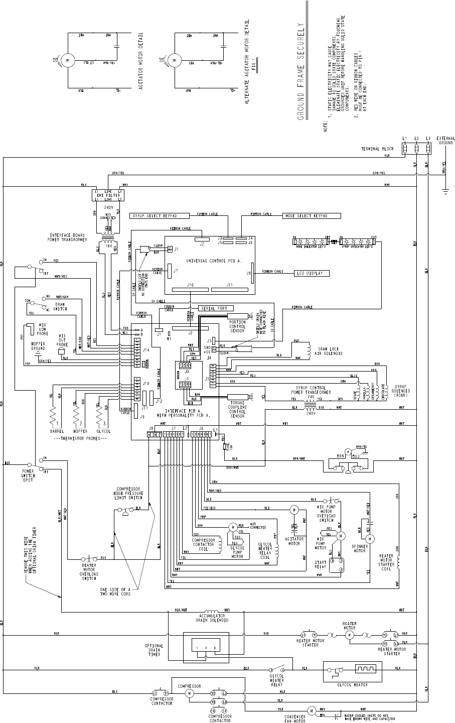
PH61
044816-33
8/07
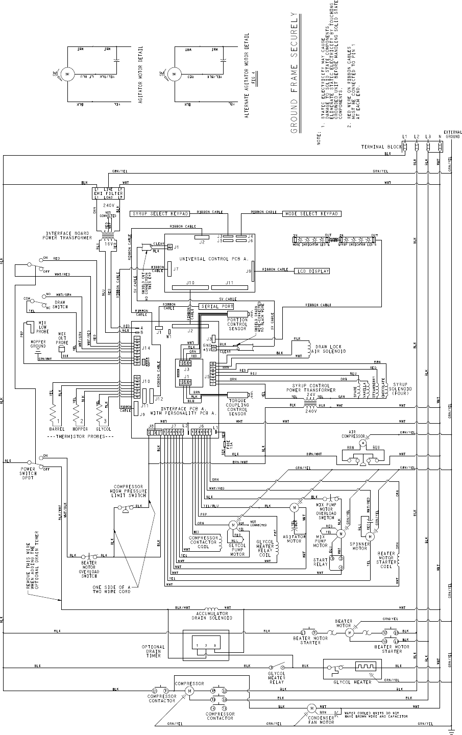
PH61
044816-62
8/07
