Carrier T 298 Users Manual
T--298 to the manual ade90665-5195-4046-a0b1-f9a4d5925d23
2015-01-24
: Carrier Carrier-T-298-Users-Manual-310558 carrier-t-298-users-manual-310558 carrier pdf
Open the PDF directly: View PDF ![]() .
.
Page Count: 49
RTransport Air Conditioning
T--298 Rev D
SERVICE MANUAL
for
MODEL AirV
Rooftop Air Conditioning Systems
RTransport Air Conditioning
2P
CFH
1
2
BLK
BLU
WHT
WHT
EVAP.
GRN/YEL
WHTBRN
12YEL
RED BLU
R
C
S
RED
PTC
BLU

SERVICE MANUAL
For
MODELS
68RV11302A
68RV14102A
68RV14103A
68RV14112A
68RV15102A
68RV15103A
AirV
AIR CONDITIONING AND
HEATING EQUIPMENT
T-298
Safety-- i
SAFETY SUMMARY
GENERAL SAFETY NOTICES
The following general safety notices supplement the specific warnings and cautionsappearing elsewherein
this manual. They are recommended precautions that must be understood and applied during operation and
maintenanceoftheequipmentcoveredherein.Thegeneralsafetynoticesarepresentedinthefollowingthree
sections labeled: First Aid, Operating Precautions and Maintenance Precautions. A listing of the specific
warnings and cautions appearing elsewhere in the manual follows the general safety notices.
FIRST AID
An injury, no matter how slight, should never go unattended. Always obtain first aid or medical attention
immediately.
OPERATING PRECAUTIONS
Always wear safety glasses.
Keep hands clear of the evaporator blower and condenser fan.
No work should be performed on the unit until all circuit breakers and start--stop switches are turned off, and
power supply is disconnected.
Always work in pairs. Never work alone.
In case of severe vibration or unusual noise, stop the unit and investigate.
MAINTENANCE PRECAUTIONS
Beware of unannounced starting of the evaporator blower & condenser fan. Do not remove the ceiling grill
assemblyor theupper unit cover assembly beforeturning thepower off, and disconnecting the power supply.
Before disconnecting, discharge capacitors by shorting across the capacitors terminals. (See Paragraph
3.5.8)
When disassembling wiring, use numbered stickers to identify wire leads and terminals. This aids in quick,
accurate reassembly.
Besurepoweristurnedoffbeforeworkingonmotors,controllers,orelectricalcontrolswitches.Taganycircuit
breakers and power supply to prevent accidental energizing of circuits.
Do not bypass any electrical safety devices, e.g. bridging an overload, or using any sort of jumper wires.
Problems with the system should be diagnosed and any necessary repairs must be performed by qualified
service personnel.
In case of electrical fire, open circuit switch and extinguish with CO2(never use water).
Usedrynitrogentopressurizethesystemforleakchecking.Becarefulnottoexceed150psigtest pressurein
the hermetic compressor.
Coil fins are sharp. Use care when removing the cover form the base pan to avoid personal injury.
Oil vapor in piping stubs can ignite from torch flame and cause serious injury. Exercise extreme care when
brazing, and keep brazing cloth and fire extinguisher handy for emergency use.
Disconnect power to the AirV unit before checking the capacitor.
T--298 Safety-- ii
SPECIFIC WARNING AND CAUTION STATEMENTS
The statements listed below are applicable to the refrigeration unit and appear elsewhere in this manual.
These recommended precautions must be understood and applied during operation and maintenance of the
equipment covered herein.
SPECIFIC WARNINGS AND CAUTIONS
WARNING
Be sure to observe warnings listed in the safety summary in the front of this manual before
performing maintenance on the AirV system
WARNING
Beforeworkingontheunitbesuretofirstdisconnectallelectricpowertotheunittoavoidthe
possibility of electrical shock and personal injury. Before disconnecting, discharge capaci-
tors by shorting across the capacitors terminals (Refer to paragraph 3.5.8)
WARNING
Shield coils with cardboard to protecthands againstinjuryfromsharp metaledgeswhen re-
moving compressor and other components.
WARNING
Oil vapor in piping stubs can ignite from torch flame and cause serious injury. Exercise ex-
treme care when brazing, and keep brazing cloth and fire extinguisher handy foremergency
use.
WARNING
Disconnect power to the AirV unit before checking the capacitor.
WARNING
Do not touch the metal of thescrewdriverwhen discharging the capacitor. You could receive
a shock.
WARNING
Before installing thermostat, turn off all power to unit. There may be more than one power
disconnect. Electrical shock can cause personal injury or death.
CAUTION
Do not use carbon tetrachloride, solvents, or waxes containing solventsto clean plastic sec-
tions.
T-298
Safety--iii
CAUTION
Coil fins are sharp. Use care when removing the cover form the base pan to avoid personal
injury.
CAUTION
ThechangefromFahrenheittoCelsiuswillbepermanent.ItcannotbechangedbacktoFahr-
enheit.
CAUTION
When re--assembling, ensure the battery springs are correctly placed in the battery spring
holders.
CAUTION
Improper wiring or installation may damage thermostat. Wiring must conform to local and
national electrical codes.

iT--298
TABLE OF CONTENTS
PARAGRAPH NUMBER Page
DESCRIPTION 1-1...............................................................................
1.1 INTRODUCTION 1-1.....................................................................
1.2 SERIAL NUMBER IDENTIFICATION 1-1....................................................
1.3 DESIGN CHANGE DESCRIPTIONS 1-1....................................................
1.4 AirV SYSTEM COMPONENT SPECIFICATIONS 1-9.........................................
1.4.1 Refrigerant Charge 1-9................................................................
1.4.2 Compressor - 115 Volts, 60 Cycles, 1 Phase 1-9..........................................
1.4.3 Compressor - 220 Volts, 50 Cycles, 1 Phase 1-9..........................................
1.4.4 Thermostat Range (All Free Blow Units) 1-9..............................................
1.5 START-UP 1-9...........................................................................
1.6 REFRIGERANT CYCLE-STANDARD SYSTEM 1-9...........................................
1.7 REFRIGERANT CYCLE - HEAT PUMP 1-10..................................................
1.7.1 Cooling 1-10..........................................................................
1.7.2 Heating 1-11..........................................................................
TROUBLESHOOTING 2-1.........................................................................
2.1 NO POWER TO UNIT 2-1.................................................................
2.2 DUCTED UNIT WILL NOT OPERATE 2-1...................................................
2.3 DUCTED UNIT WILL NOT COOL 2-1.......................................................
2.4 COMPRESSOR POWER SUPPLY OPEN 2-1...............................................
2.5 COMPRESSOR RUNS BUT CYCLES, FAN OPERATING ERRATICALLY 2-1....................
2.6 CYCLES ON COMPRESSOR OVERLOAD 2-2..............................................
2.7 INSUFFICIENT COOLING, COOLING AIR NOT ADEQUATE 2-2..............................
2.8 CONDENSER AIR NOT ADEQUATE 2-2....................................................
2.9 INSUFFICIENT COOLING 2-2.............................................................
2.10 COMPRESSOR FLOODING 2-2...........................................................
2.11 HEATER CYCLES ON LIMIT SWITCH (HEAT/ COOL VERSION ONLY) 2-2.....................
2.12 AIR SWEEP NOT WORKING (FREE BLOW VERSION ONLY) 2-2.............................
2.13 WATER LEAKAGE 2-2....................................................................
2.14 INADEQUATE HEAT (FREE-BLOW HEAT ONLY) 2-3........................................
2.15 INADEQUATE HEAT (HEAT-PUMP) 2-3....................................................
Clearing Diagnostic Alarms 2-3...................................................................
SERVICE AND MAINTENANCE 3-1................................................................
3.1 PREVENTATIVE MAINTENANCE 3-1......................................................
3.2 SERVICE - GENERAL 3-1................................................................
3.3 CEILING UNIT - FREE BLOW SYSTEMS 3-1...............................................
3.3.1 Filter Removal 3-1....................................................................
3.3.2 Ceiling Grill Removal 3-1..............................................................
3.3.3 Ceiling Panel Removal 3-2.............................................................
3.3.4 Master Control Switch 3-2.............................................................
3.3.5 Air Sweep Switch Removal 3-2.........................................................
3.3.6 Indoor Thermostat Removal 3-3........................................................
3.3.7 Air Sweep Removal 3-3...............................................................
3.3.8 Heat Strip Assembly Removal 3-3......................................................
ii
T--298
TABLE OF CONTENTS - Continued
3.4 CEILING UNIT - DUCTED SYSTEMS 3-4...................................................
3.4.1 Filter Removal 3-4....................................................................
3.4.2 Ceiling Grill Removal 3-4..............................................................
3.4.3 Control Box Assembly Removal 3-4.....................................................
3.4.4 Main PCB Board Removal 3-5..........................................................
3.4.5 PCB Display Removal 3-5.............................................................
3.4.6 Fuse Removal 3-5....................................................................
3.5 SERVICE - UPPER UNIT - STANDARD, HC & HP 3-5........................................
3.5.1 Exterior Cover Removal 3-5............................................................
3.5.2 Compressor Replacement 3-6..........................................................
3.5.3 Control Box Assembly Removal 3-6.....................................................
3.5.4 Upper Scroll Assembly Removal 3-7....................................................
3.5.5 Motor Assembly and Condenser Fan Removal 3-7........................................
3.5.6 Evaporator Blower Wheel Adjustment or Removal 3-8.....................................
3.5.7 Air Handling System Removal 3-8......................................................
3.5.8 Capacitor Troubleshooting 3-9..........................................................
3.5.9 Capacitor Testing and Replacement 3-9.................................................
3.5.10 Positive Temperature Coefficient Thermister (PTC) (Start Thermistor) Troubleshooting 3-9.....
3.5.11 Line Voltage - 10% 3-9................................................................
3.6 SERVICE - UPPER UNIT - LOW PROFILE 3-10..............................................
3.6.1 Exterior Cover Removal 3-10............................................................
3.6.2 Upper Scroll Assembly Removal 3-10....................................................
3.6.3 Condenser Fan Assembly Removal 3-11..................................................
3.6.4 Condenser Motor Removal 3-12.........................................................
3.6.5 Evaporator Motor/Blower Assembly Removal 3-12.........................................
3.6.6 Compressor Replacement 3-13..........................................................
3.6.7 Capacitor Removal 3-13................................................................
3.6.8 Remote Control (Fahrenheit to Celsius) 3-13..............................................
3.7 THERMOSTAT INSTALLATION AND START-UP INSTRUCTIONS (WALL MOUNTED) 3-15........
3.7.1 Introduction 3-15......................................................................
3.7.2 Installation 3-15.......................................................................
3.7.3 Thermostat Location 3-15...............................................................
3.7.4 Install Thermostat - 12VDC 3-15.........................................................
3.8 LCD DISPLAY 3-15.......................................................................
3.8.1 Cool Only Thermostat 3-15.............................................................
3.8.2 Heat/Cool Thermostat 3-15.............................................................
3.9 SET THERMOSTAT CONFIGURATION 3-15.................................................
3.9.1 Enter Configuration Mode 3-15..........................................................
3.10 CHECK THERMOSTAT OPERATION 3-16...................................................
3.10.1 Fan Operation (Cool Only) 3-16..........................................................
3.10.2 Fan Operation (Heat/Cool) 3-16.........................................................
3.10.3 Cooling Operation (Cool Only) 3-16......................................................
3.10.4 Cooling Operation (Heat/Cool) 3-16......................................................
3.10.5 Heating Operation (Heat/Cool) 3-16......................................................

iii T--298
TABLE OF CONTENTS - Continued
3.11 CHECK THERMOSTAT OPERATION 3-16...................................................
3.11.1 Temperature Display 3-16...............................................................
3.11.2 Timeguard Timer 3-17..................................................................
3.11.3 Cycle Timer 3-17......................................................................
3.11.4 Minimum On Timer 3-17................................................................
3.11.5 Error Messages 3-17...................................................................
WIRING SCHEMATICS 4-1........................................................................
4.1 INTRODUCTION 4-1.....................................................................
LIST OF FIGURES
FIGURE NUMBER Page
Figure 1-1 Model/Serial Number Plate (Typical) 1-1...................................................
Figure 1-2 Roof Unit Component Identification 1-3....................................................
Figure 1-3 Ceiling Unit Component Identification (Free-Blow) 1-4.......................................
Figure 1-4 Component Identification - Low Profile - Upper Unit 1-5......................................
Figure 1-5 Component Listing-Ceiling Unit For Ducted Systems 1-6....................................
Figure 1-6 Ducted System Air Flow Arrangement 1-7.................................................
Figure 1-7 Serial Number Locations 1-8.............................................................
Figure 1-8 Refrigerant Flow Schematic (Standard System) 1-9.........................................
Figure 1-9 Refrigerant Flow Schematic - Heat Pump - (Cool Mode) 1-10.................................
Figure 1-10 Refrigerant Flow Schematic - Heat Pump - (Heat Mode) 1-11................................
Figure 3-1 Filter Removal - Free Blow 3-1...........................................................
Figure 3-2 Ceiling Grill - Free Blow 3-2..............................................................
Figure 3-3 Ceiling Panel Assembly 3-2..............................................................
Figure 3-4 Ceiling Panel With Heat Option 3-2.......................................................
Figure 3-5 Control Box Assembly - Free Blow 3-2....................................................
Figure 3-6 Indoor Thermostat 3-3..................................................................
Figure 3-7 Air sweep motor 3-3....................................................................
Figure 3-8 Heat Strip Assembly 3-3................................................................
Figure 3-9 Filter Removal - Ducted Unit 3-4.........................................................
Figure 3-10 Ceiling Grill - Ducted 3-4...............................................................
Figure 3-11 Control Box & PCB Cover 3-4...........................................................
Figure 3-12 Control Box Assembly - Ducted 3-5......................................................
Figure 3-13 Main/Display PCB’s 3-5................................................................
Figure 3-14 Cover Assembly - Standard 3-5.........................................................
Figure 3-15 Control Box 3-6.......................................................................
Figure 3-16 Control Box Removal 3-6...............................................................
Figure 3-17 Water Cover Removal 3-6..............................................................
Figure 3-18 Upper Scroll Assembly 3-7.............................................................
Figure 3-19 Motor Assembly 3-7...................................................................
Figure 3-20 Spring Clamp Removal 3-7.............................................................
Figure 3-21 Motor Clip Removal 3-7................................................................
Figure 3-22 Condenser Fan Removal 3-8...........................................................
Figure 3-23 Blower Wheel 3-8.....................................................................
Figure 3-24 Condenser With Motor Assembly & Compressor 3-8.......................................
Figure 3-25 Set-Up For Discharging a Capacitor 3-9..................................................

iv
T--298
LIST OF FIGURES
Figure 3-26 Cover Assembly - Low Profile 3-10.......................................................
Figure 3-27 Upper Scroll Assembly Locking Tabs (b.) & Screw Locations (c.) 3-10.........................
Figure 3-28 Upper Scroll Assembly Keeper Tab Release 3-10...........................................
Figure 3-29 Upper Scroll & Control Box Cover Removed 3-11...........................................
Figure 3-30 Condenser Fan Assembly & Retaining Ring 3-11...........................................
Figure 3-31 Condenser Fan Motor & Fan Assembly Stop 3-11..........................................
Figure 3-32 Condenser Fan Motor & Fan Assembly Tab 3-11...........................................
Figure 3-33 Condenser Motor Ground 3-12...........................................................
Figure 3-34 Evaporator Motor Locking Tabs 3-12......................................................
Figure 3-35 Evaporator Motor/Blower Assembly In Cradle 3-12.........................................
Figure 3-36 Evaporator Blower Wheel (Flush With End Of Motor Shaft) 3-13..............................
Figure 3-37 Control Box Assembly With Capacitor 3-13................................................
Figure 3-38 Remote Control Components 3-14........................................................
Figure 3-39 Remote Control PCB (FR9 Location) 3-14.................................................
Figure 3-40 Wall Thermostat Wiring Diagram - Cool Only Model 3-17....................................
Figure 3-41 Wall Thermostat Wiring Diagram - Heat/Cool Model 3-18....................................
Figure 4-1 Upper Unit Schematic - Standard & HC 4-1................................................
Figure 4-2 Upper Unit Schematic - Low Profile 4-1...................................................
Figure 4-3 Ceiling Unit Schematic - Cooling Only 4-2.................................................
Figure 4-4 Ceiling Unit Schematic - Heat/Cool 4-2....................................................
Figure 4-5 Ceiling Unit, Standard - Ducted 4-2.......................................................
Figure 4-6 Heat Pump - Upper Unit - Free Blow 4-3..................................................
Figure 4-7 Heat Pump - Ceiling Unit - Free Blow 4-3..................................................
Figure 4-8 Heat Pump - Upper Unit - Ducted 4-4.....................................................
Figure 4-9 Heat Pump - Ceiling Unit - Ducted 4-4....................................................
LIST OF TABLES
TABLE NUMBER Page
Table 1-1 Model Chart 1-2.........................................................................
Table 1-2 Additional Support Manuals 1-3............................................................
Table 2-1 System Self-diagnostics Function (Ducted Remote) 2-4.......................................
T--298
1-1
SECTION 1
DESCRIPTION
1.1 INTRODUCTION
This manualcontains service instructions and electrical
data for the AirV, Carrier Transport Air Conditioning’s
Recreational Vehicle air conditioning unit.
The AirV units are two piece systems, consisting of the
UpperUnit andtheCeilingunit.TheUpperUnitcontains
the refrigeration system while the Ceiling Unit contains
thecontrolsandvents.TheCeilingUnitsareavailablein
a free--blow or ducted configuration.
The free--blow units (see Figure 1-2) deliver air to the
vehicle by means of front and rear end vents and one
downward vent (air shower). The vents may all be
opened or closed to direct air as desired. The front and
rear vents are fitted with motorized dampers that
oscillates to produce an “air--sweep” effect. These units
may be fitted with optional electric heat.
Theductedunits(seeFigure 1-5andFigure 1-6)deliver
air through ducting built in the vehicle ceiling. These
units are fitted with a 12 VDC microprocessor control
system, a display panel (PCB display) and a remote
controller. These units may be wired to provide
thermostatic control of the vehicle furnace.
Carrier’s AirV air conditioning models include cooling
only units, heating/cooling units, and heat pump units.
The cooling only units are available with free blow or
ducted air delivery. Cooling units with heat strips are
available for free blow only.
OperationoftheAirVunitsiscontrolledautomaticallyby
the temperature controller (thermostat), which
maintains the vehicle’s interior temperature at the
desired set point. Free Blow, cool--only units are
available with a wall mounted thermostat.
Table 1-1 lists model numbers and descriptions of the
AirV units, and Table 1-2 lists additional support
manuals that are available.
1.2 SERIAL NUMBER IDENTIFICATION
Separatepartnumbersandserialnumbersareprovided
for the upper and lower unit assemblies The numbers
may be found on a plate readable from inside the
vehicle, See Figure 1-7.
The first two numbers of the serial number, see
Figure 3-22,is theweektheunitwasmanufactured.For
example, 01 would designate the first week of the year
and 52 would designate the last week of the year.
The third and fourth numbers designate the year in
which the unit was manufactured. For example, 99
would represent the year 1999, 00 the year 2000, and
so on.
The letter Y and all the numbers after it designates the
unit serial number. Example: Y43210
A serial numberof 1303Y12345 designatesthat theunit
was manufactured the 13th week of 2003 and the serial
number is Y12345.
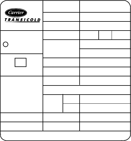
MODEL No.
Part No.
VOLTS
ph
CAPACITY
AMPS
DATE OF Mfg
SERIAL No.
DESIGN PSIG HIGH 350 LO 150
oz
kg
RLA
FLA
R--22
USE CEILING ASSY/ANY
COMPRESSOR
FAN MOTOR
68RV14102A
99--00468--01
V
115
1hz 60
13,500 Btu/h
3,955 W
13.5 A
05/03
1303Y12345
15.9
0.45
12.5
2.58
99--00469--01
Carrier
Air Conditioning
C
Division of Carrier Corporation
USE AMP20
TIME DELAY FUSE OR
CIRCUIT BREAKER
Figure 1-1 Model/Serial Number Plate (Typical)
1.3 DESIGN CHANGE DESCRIPTIONS
The following list provides a description of changes in
design and serial number breaks for those changes.
1400Y A diode was added to the Ducted Ceiling
assembly control board to stop DC ripple from the
converters,
2900Y Cover screw coating was changed in order to
eliminate corrosion.
3400Y The plastic shroud was modified to improve
drainage.
5100Y A new compressor and capacitor is introduced,
improving stability and increasing capacity.
1201Y The temperature sensor was moved to the grill
to improve temperature sensing during furnace mode,
2501Y The dual air sweep was added.
4501Y A switch was added to skip compressor
malfunction test.
4601Y Change in material was made in order to
strengthen the fan propeller.
4901Y The mounting bolt lengths were increased 3/4
inch.
4901Y The polar white ducted ceiling color wascut--in.
0703Y & 1903Y New style PCB -- Cool Mode -- Control
& Power Assembly (Fans shut off in auto mode).
0803Y & 2603Y New style PCB -- Heat Pump -- Control
& Power Assembly (Fans shut off in auto mode).
4204Y Minimumfurnacesetpointloweredfrom 63°Fto
45°F.
T--298 1-2
Table 1-1. Model Chart
UPPER UNIT (ROOF)
Model Number Part Number Voltage Amps Color
115
V
Standard S
y
stem 99--00468--00 115/1/60 12.8 White
1
1
5
V
S
t
a
n
d
a
r
d
S
y
s
t
e
m
68RV14102A 99--00468--01 115/1/60 12.8 Ivory
220
V
Standard S
y
stem 99--00468--02 220/1/50 5.3 Cool White
2
2
0
V
S
t
a
n
d
a
r
d
S
y
s
t
e
m
68RV11302A 99--00468--03 220/1/50
5
.
3
C
o
o
l
6.7 Heat Ivory
Hi
g
hCa
p
acit
y
99--00468--08 115/1/60 14.5 White
H
i
g
h
C
a
p
a
c
i
t
y
68RV15102A 99--00468--09 115/1/60 14.5 Ivory
99--00468--04
(Free Blow) 115/1/60 12.7 Cool
10.9 Heat White
Heat Pump
S
y
s
t
e
m
s
99--00468--05
(Free Blow) 115/1/60 12.7 Cool
10.9 Heat Ivory
Systems
68RV14112A 99--00468--06
(Ducted) 115/1/60 12.7 Cool
10.9 Heat White
99--00468--07
(Ducted) 115/1/60 12.7 Cool
10.9 Heat Ivory
LOW PROFILE
68RV15103A 99--00468--10
(Free Blow -- High Capacity) 115/1/60 15.1 Cool
13.8 Heat White
LOW PROFILE
68RV14103A 99--00468--12
(Free Blow -- Standard) 115/1/60 15.0 Cool
13.7 Heat White
CEILING UNIT
Model Number Part Number Voltage Color Options Interface
6
8
R
V
0
0
1
0
A
A
99--00469--00 115/1/60 White Cool Only Free Blow
68
R
V
0010
A
A
99--00469--01 115/1/60 Ivory Cool Only Free Blow
6
8
R
V
0
0
1
0
B
A
99--00469--02 115/1/60 White Heat/Cool Free Blow
68
R
V
0010
B
A
99--00469--03 115/1/60 Ivory Heat/Cool Free Blow
68RV0010KA 99--00469--06 115/1/60 (12VDC) White Cool Only Ducted
6
8
R
V
0
0
3
0
A
A
99--00469--04 220/1/50 White Cool Only Free Blow
68
R
V
0030
A
A
99--00469--05 220/1/50 Ivory Cool Only Free Blow
68RV0030BA 99--00469--08 220/1/50 White Heat/Cool Free Blow
68RV0030KA 99--00469--10 220/1/50 White Cool Only Ducted
6
8
R
V
0
0
1
2
C
A
99--00469--11 115/1/60 White Heat Pump Free Blow
68
R
V
0012
C
A
99--00469--12 115/1/60 Ivory Heat Pump Free Blow
68RV0011LA 99--00469--13 115/1/60 (12VDC) White Heat Pump Ducted
68RV0010AB 99--00469--23 115/1/60 White Cool Only Free Blow
68RV0010AB 99--00469--24 115/1/60 Ivory Cool Only Free Blow
68RV0010BB 99--00469--25 115/1/60 White Heat/Cool Free Blow
68RV0010BB 99--00469--26 115/1/60 Ivory Heat/Cool Free Blow
68RV0040MA 99--00469--22 115/1/60 White Cool Only Ducted
Wall Thermostat
68RV0010DB 99--00469--29 115/1/60 White Cool Only Free Blow
Wall Thermostat
T--298
1-3
Table 1-2 Additional Support Manuals
MANUAL--FORM NO. EQUIPMENT COVERED TYPE OF MANUAL (For) PART NO.
71LC6A54310 AirV 115 Volts--Free Blow (Cool Only) Owner’s Guide 99--00469--00
99--00469--01
71LH6A54070 AirV 115 Volts--Free Blow (Heat--Cool) Owner’s Guide 99--00469--02
99--00469--03
71LD6A54070 AirV 115 Volts--Ducted (Cool Only) Owner’s Guide 99--00469--06
71LH6A54070 AirV 220 Volts--Free Blow (Heat--Cool) Owner’s Guide 99--00469--08
99--00469--09
71RQ6A5401A AirV 115 Volts--Free Blow (Heat Pump) Owner’s Guide 99--00469--11
99--00469--12
71DQ6A5401A AirV 115 Volts--Ducted (Heat Pump) Owner’s Guide 99--00469--13
71DW6A54070 AirV 115 Volts--Ducted Wired Thermostat Owner’s Guide 99--00469--22
71LC6A54310 AirV 115 Volts--Free Blow (Cool Only) Owner’s Guide 99--00469--23
99--00469--24
71LH6A54070 AirV 115 Volts--Free Blow (Heat--Cool) Owner’s Guide 99--00469--25
99--00469--26
71RW6A54310 AirV 115 Volts--Free Blow Wired Thermostat Owner’s Guide 99--00469--29
T--298PL AirV Service Parts ALL
62--50455--00 Basic refrigeration Service Training ALL
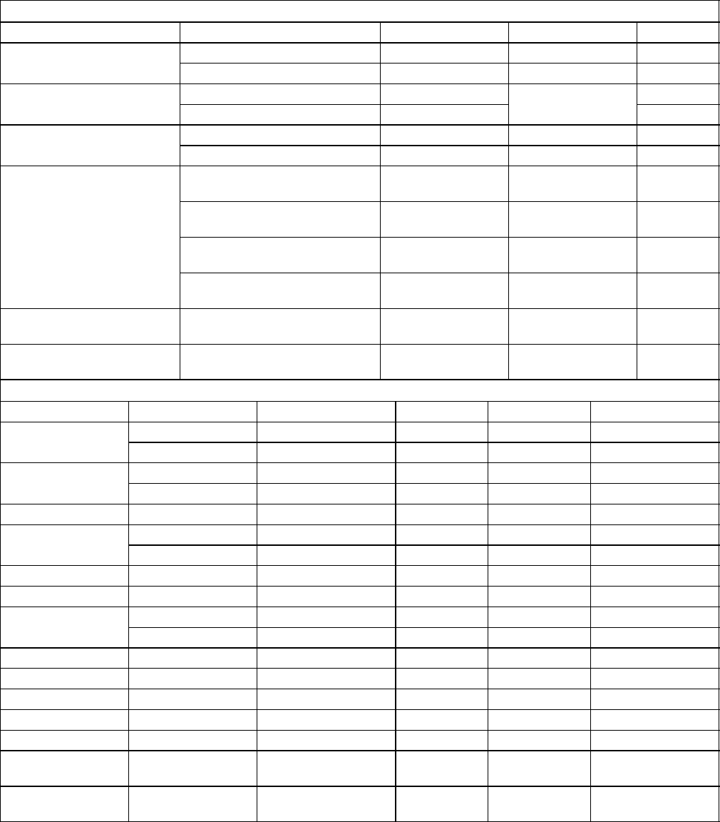
1
2
4
5
3
1. Cover
2. Condenser
3. Evaporator
4. Compressor
5. Base Pan
Figure 1-2 Roof Unit Component Identification
T--298 1-4
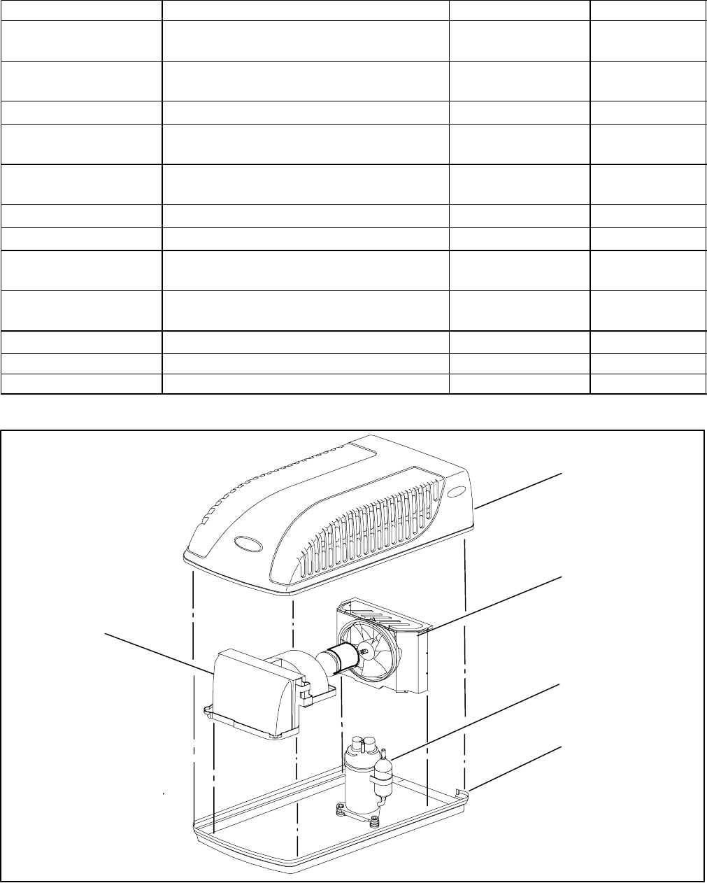
1
2
3
4
1. Ceiling Panel Assembly
2. Control Box Cover 3. Control Assembly
4. Ceiling Grill Assembly
Figure 1-3 Ceiling Unit Component Identification (Free--Blow)
T--298
1-5
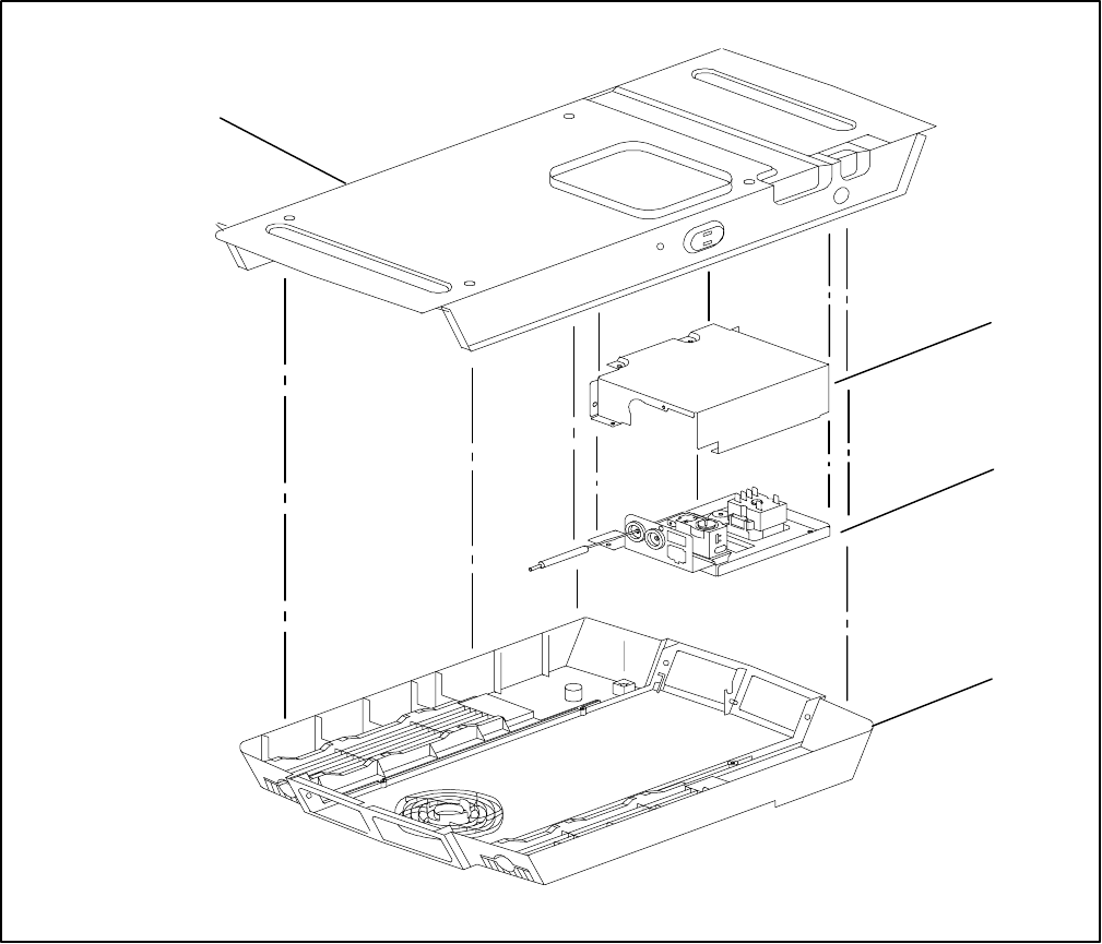
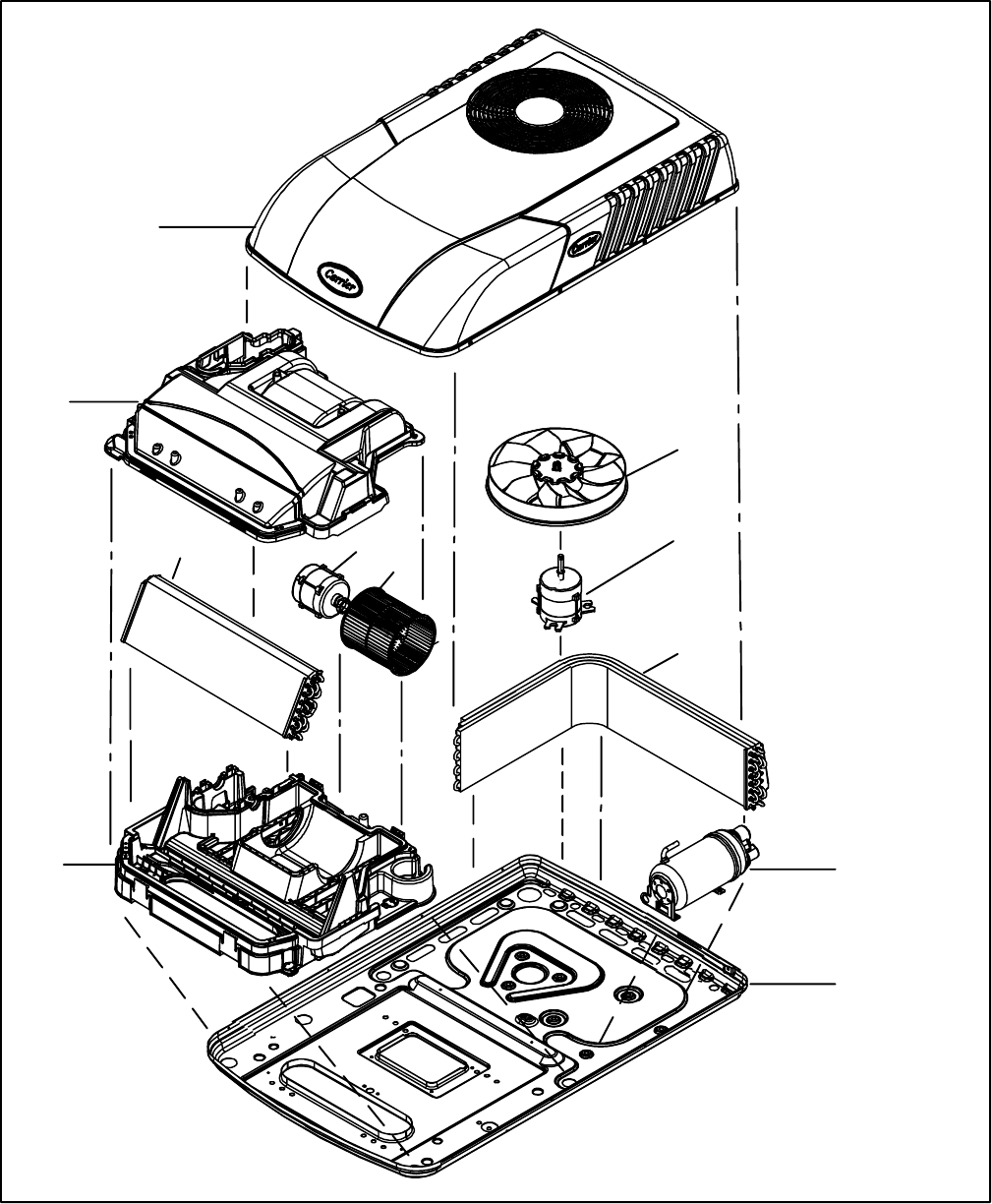
1
2
3
4
56
8
7
9
10
11
1. Cover Assembly
2. Scroll Assembly -- Upper
3. Condenser Fan
4. Condenser Motor
5. Evaporator Motor
6. Evaporator Blower Wheel
7. Condenser Coil
8. Scroll Assembly -- Lower
9. Evaporator Coil
10. Compressor
11. Base Pan Assembly
See Figure 1-3 for Ceiling Package (Free--Blow)
Figure 1-4 Component Identification -- Low Profile -- Upper Unit
T--298 1-6
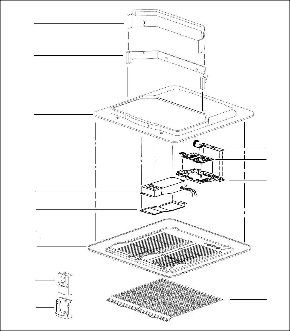
1
2
3
4
5
6
7
89
10
11
12
1. Telescoping Divider (3 different sizes available)
2. Divider Assembly
3. Frame Panel, Insulation Assembly
4. Control Box Assembly
5. Control Box Cover
6. Suction Packing Assembly
7. Remote Control Assembly
8. Remote Control Bracket Assembly
9. Filter Assemblies (2)
10. PCB Cover
11. PCB Main Assembly
12. PCB Display
Figure 1-5 Component Listing--Ceiling Unit For Ducted Systems
T--298
1-7
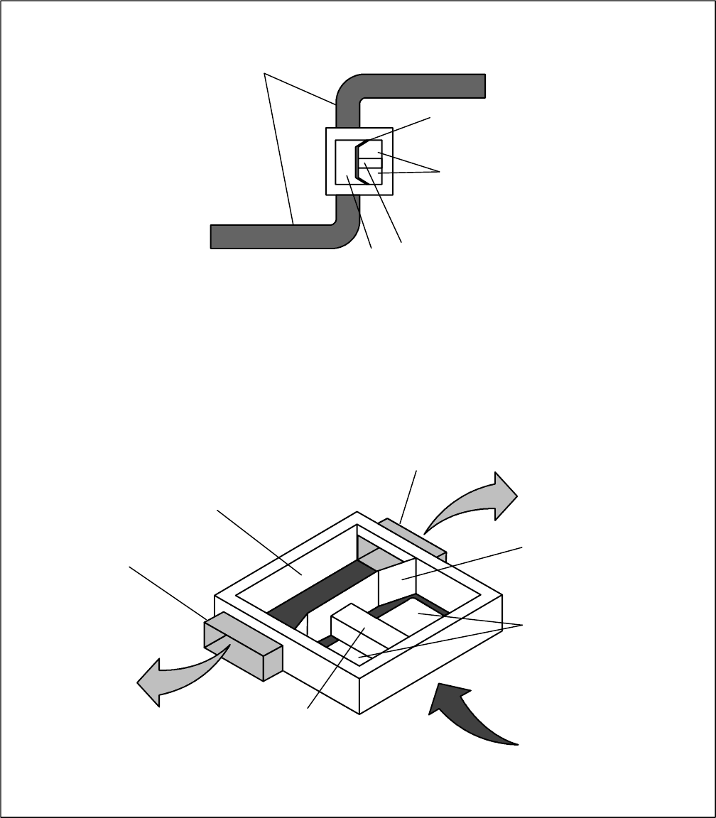
1
2
3
4
5
SCHEMATIC VIEW
INSTALLED VIEW
3
2
1
1
4
5SUPPLY AIR
RETURN AIR
SUPPLY AIR
1. Vehicle Duct System (Connection)
2. Telescoping Divider (3 different sizes available)
3. Return Air Suction Area
4. Control Box Assembly
5. Supply Air Discharge Area
Figure 1-6 Ducted System Air Flow Arrangement
T--298 1-8
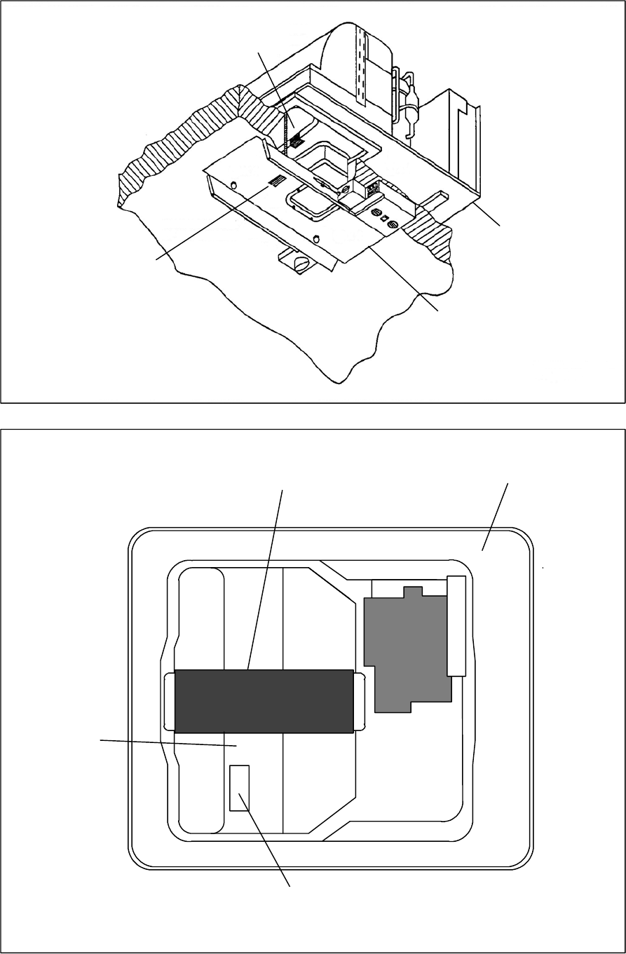
Serial Number
of Ceiling Unit
Serial number
of Upper Unit
Upper Unit
Ceiling Unit
(Cover Removed)
Free Blow Type
Bottom View After Installation
(With Grille Removed)
Ceiling Assembly Frame
Serial Number of
Ceiling Unit
(Side of Control Box)
Bottom of
Upper Unit
Serial Number
of Upper Unit
Ducted Type
Figure 1-7 Serial Number Locations
T--298
1-9
1.4 AirV SYSTEM COMPONENT SPECIFI-
CATIONS
1.4.1 Refrigerant Charge
Standard -- High Capacity -- Heat Pump
R--22 -- 15.9 Ounces
Low Profile (All)
R--22 -- 16.9 Ounces
1.4.2 Compressor -- 115 Volts, 60 Cycles, 1 Phase
a. Locked Rotor Amps -- Standard -- High
Capacity -- Heat Pump
64.5 AMPS6
b. Locked Rotor Amps -- Low Profile
High Capacity
59.0 AMPS
c. Fully Loaded Amps -- Standard
Cooling -- Approximate 12.8 AMPS
Heating -- N/A
d.Fully Loaded Amps -- High Capacity
Cooling -- Approx. 14.5 AMPS
Heating -- Approx. 11 AMPS
e. Fully Loaded Amps -- Low Profile
Cooling -- Approx. 14.1 AMPS
Heating -- Approx. 13.8 AMPS
f. Fully Loaded Amps -- Heat Pump
Cooling -- Approx. 12.8 AMPS
Heating -- Approx. 11 AMPS
1.4.3 Compressor -- 220 Volts, 50 Cycles, 1 Phase
a. Locked Rotor Amps
23.6 AMPS
1.4.4 Thermostat Range (All Free Blow Units)
61°F(16°C) to 89°F(32°C)
1.5 START--UP
Refer to operating instructions in Owners Guide (see
Table 1-2) packaged with the vehicle system.
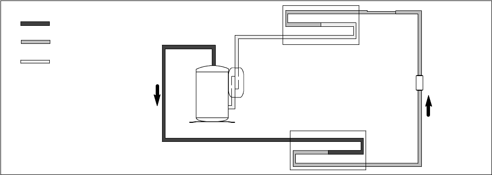
COMPRESSOR
ACCUMULATOR
CONDENSER
EVAPORATOR
CAPILLARY
TUBE
STRAINER
DISCHARGE
SUCTION
LIQUID
Figure 1-8 Refrigerant Flow Schematic (Standard System)
1.6 REFRIGERANT CYCLE--STANDARD SYSTEM
The cooling cycle is energized when the thermostat,
located on the ceiling unit, calls for cooling. The main
components of the system are the compressor,
air-cooled condenser coil, strainer, capillary tube,
evaporator coil and accumulator.
The compressor raises the pressure and the
temperature of the refrigerant and forces it through the
dischargeline intothe condenser coil. (SeeFigure 1-8.)
The condenser fan circulates surrounding air (which is
at a temperature lower than the refrigerant) over the
outside of the coil tubes. Heat transfer is established
from the refrigerant (inside the tubes) to the air (flowing
over the tubes). The tubes have fins designed to
improve the transfer of heat from the refrigerant gas to
the air. This removal of heat causes the refrigerant to
liquefy, thus liquid refrigerant leaves the coil and flows
through a strainer to the capillary tube. The strainer
removes any impurities within the refrigerant system.
The capillary tube meters the flow of liquid refrigerant to
the evaporator coil. As the refrigerant flows through the
capillary tube, there is a reduction in pressure and
temperature.
Theevaporatorblower(fan)pulls vehicleairthroughthe
filters, which remove particulate matter, and then pass
the cleaned air through the evaporator coil.
The low pressure, low temperature liquid that flows into
the evaporator coil tubes is colder than the air that is
circulated over the tubes. Heat transfer is established
from the vehicle air (flowing over the tubes) to the
refrigerant (flowing inside the tubes). The evaporator
coil tubes have aluminum fins to increase heat transfer
from the air to the refrigerant; therefore the cooler air is
circulated to the interior of the vehicle.
The transfer of heat from the air to the low temperature
liquid refrigerant in the indoor coil causes the liquid to
vaporize. This low temperature, low pressure vapor
passes into the accumulator. The accumulator is
designed with the inlet tube delivering refrigerant to the
bottom of the tank and the outlet tube taking refrigerant
form the top of the tank. This arrangement ensures that
only vapor refrigerant is returned to the compressor,
where the cycle repeats.
When ventilation only is selected, the indoor fan
functions to circulate air throughout the vehicle. The
refrigerant cycle will remain off.
T--298 1-10
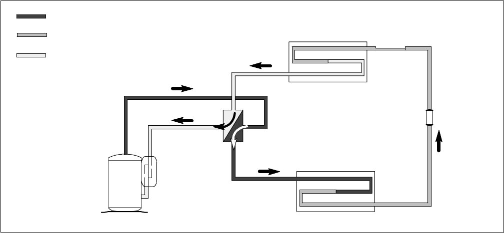
1.7 REFRIGERANT CYCLE -- HEAT PUMP
STRAINER
OUTDOOR COIL
INDOOR COIL
REVERSING VALVE
ACCUMULATOR
COMPRESSOR
CAPILLARY
TUBE
DISCHARGE
SUCTION
LIQUID
Figure 1-9 Refrigerant Flow Schematic -- Heat Pump -- (Cool Mode)
1.7.1 Cooling
The cooling cycle is energized when the thermostat,
located in the ceiling unit, calls for cooling The system
controlsarepositionedfor“normal”refrigerantflow,with
the compressor discharge delivered to the outdoor coil
and liquid delivered to the indoor coil. (See Figure 1-9.)
The main components of the system are the
compressor, reversing valve, air-cooled outdoor coil,
strainer,capillarytube,indoor coil,andtheaccumulator.
The compressor raises the pressure and the
temperature of the refrigerant and forces it through the
discharge line and reversing valve into the outdoor coil.
The outdoor fan circulates surrounding air (which is at a
temperature lower thanthe refrigerant) over the outside
of the coil tubes. Heat transfer is established from the
refrigerant (inside the tubes) to the outdoor air (flowing
over the tubes). The tubes have fins designed to
improve the transfer of heat from the refrigerant gas to
the air; this removal of heat causes the refrigerant to
liquefy, thus liquid refrigerant leaves the coil and flows
through the strainer to the capillary tube. The strainer
removes any impurities within the refrigerant system.
The capillary tube meters the flow of liquid refrigerant to
the indoor coil. As the refrigerant flows through the
capillary tube, there is a reduction in pressure and
temperature.
The indoor blower (fan) pulls inside air through the
filters, which remove particulate matter, and then pass
the cleaned air through the indoor coil.
The low pressure, low temperature liquid that flows into
the indoor coil tubes is colder than the air that is
circulated over the tubes. Heat transfer is established
from the indoor air (flowing over the tubes) to the
refrigerant (flowing inside the tubes). The indoor coil
tubes havealuminumfins toincreaseheat transfer from
the air to the refrigerant; therefore the cooler air is
circulated to the interior of the vehicle.
The transfer of heat from the air to the low temperature
liquid refrigerant in the indoor coil causes the liquid to
vaporize. This low temperature, low pressure vapor
passes into the accumulator. The accumulator is
designed with the inlet tube delivering refrigerant to the
bottom of the tank and the outlet tube taking refrigerant
form the top of the tank. This arrangement ensures that
only vapor refrigerant is returned to the compressor,
where the cycle repeats.
When ventilation only is selected, the indoor fan
functions to circulate air throughout the vehicle. The
refrigerant cycle will remain off.
T--298
1-11
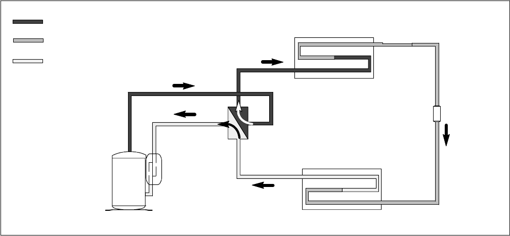
COMPRESSOR
ACCUMULATOR
REVERSING VALVE
INDOOR COIL
OUTDOOR COIL
STRAINER
CAPILLARY
TUBE
DISCHARGE
SUCTION
LIQUID
Figure 1-10 Refrigerant Flow Schematic -- Heat Pump -- (Heat Mode)
1.7.2 Heating
The heating cycle is energized when the thermostat,
located in the ceiling unit, calls for heat The system
controls are positioned for “reverse” refrigerant flow,
with the compressor discharge delivered to the indoor
coil and liquid delivered to the outdoor coil. (See
Figure 1-10.)
The main components of the system are the
compressor, reversing valve, indoor coil, capillarytube,
strainer, air-cooled outdoor coil, and the accumulator.
The compressor raises the pressure and the
temperature of the refrigerant and forces it through the
discharge line and reversing valve into the indoor coil.
The indoor blower (fan) pulls inside air through the
filters, which remove particulate matter, and then pass
the cleaned air through the indoor coil.
The vehicle air(which is ata temperature lower than the
refrigerant) passes over the outside of the coil tubes.
Heat transfer is established from the refrigerant (inside
thetubes)tothevehicleair(flowingoverthetubes).The
tubes have finsdesigned to improve the transfer of heat
from the refrigerant gas to the air; this removal of heat
causes the refrigerant to liquefy, thus liquid refrigerant
leaves the coil and flows through the strainer to the
outdoor coil. The strainer removes any impurities within
the refrigerant system.
The capillary tube meters the flow of liquid refrigerant to
the outdoor coil. As the refrigerant flows through the
capillary tube, there is a reduction in pressure and
temperature.
The low pressure, low temperature liquid that flows into
the outdoor coil tubes is colder than theoutdoor airthat
is circulated over the tubes. Heat transfer is established
from the outdoor air (flowing over the tubes) to the
refrigerant (flowing inside the tubes). The outdoor coil
tubes havealuminumfins toincreaseheat transfer from
the air to the refrigerant.
The transfer of heat from the air to the low temperature
liquid refrigerant in the outdoor coil causes the liquid to
vaporize. This low temperature, low pressure vapor
passes into the accumulator. The accumulator is
designed with the inlet tube delivering refrigerant to the
bottom of the tank and the outlet tube taking refrigerant
form the top of the tank. This arrangement ensures that
only vapor refrigerant is returned to the compressor,
where the cycle repeats.
When ventilation only is selected, the indoor fan
functions to circulate air throughout the vehicle. The
refrigerant cycle will remain off.

T--298
2-1
SECTION 2
TROUBLESHOOTING
For ducted units, the green operation indicator LED (SeeFigure 3-9) will flash if there is a problem.
Refer to Table 2--1 for diagnostic information.
SYMPTOM AND PROBABLE CAUSE PROBABLE REMEDY
2.1 NO POWER TO UNIT
1. Master switch off
2. Open circuit breaker
3. Defective wiring
4. Loose electrical connections
5. Faulty switches, thermostat, or fan
6. 12 VDC not connected (Ducted System)
7. 12 VDC in--line fuse open (Ducted)
1. Reset master switch
2. Reset circuit breaker
3. Replace wiring
4. Tighten connections
5. Replace defective components
6. Connect to 12 VDC power source
7. Replace fuse
2.2 DUCTED UNIT WILL NOT OPERATE
1. Display not illuminated
2. Display illuminated 1. Check 12 Volt DC in--line fuse
2. Check 115 Volt AC Connections
2.3 DUCTED UNIT WILL NOT COOL
1. Green LED light flashes 5 times
2. Unit cools for a few moments then stops cooling
1. Check 115 volt AC power source
Momentarily disconnect 12 VDC power source
Disable compressor malfunction test switch.
Check AMP draw.
Check ∆T
2. Remove grill, verify evaporator coil probe is
inserted into coil.
Check AMP draw.
Check ∆T
Replace unit
2.4 COMPRESSOR POWER SUPPLY OPEN
1. Loose leads at compressor terminals
2. Defective motor overload switch
3. Defective capacitor
4. Open compressor windings
5. Seized compressor
6. Capacitor incorrectly wired
1. Tighten leads
2. Replace switch
3. Replace capacitor -- Refer to Paragraph 3.5.8
4. Replace compressor
5. Replace compressor
6. Verify capacitor wiring (Refer to wiring diagram)
2.5 COMPRESSOR RUNS BUT CYCLES, FAN OPERATING ERRATICALLY
1. Loose lead at fan motor
2. Defective or burned out motor
3. Outdoor air restricted or recirculating
4. Overcharge or noncondensables in system
5. Restricted discharge line
6. Defective motor overload switch
1.Tighten lead.
2. Replace motor.
3. Check for dirty condenser coil, proper clearance
around unit, remove any obstructions.
4. Check AMP draw
5. Check for obstruction in line.
Check ∆T.
Replace unit.
6. Replace switch.

T--298 2-2
SYSTEM AND PROBABLE CAUSE PROBABLE REMEDY
2.6 CYCLES ON COMPRESSOR OVERLOAD
1. Defective run capacitor
2. Defective compressor bearings or valves
3. Greatly restricted evaporator air, iced evaporator
coil.
4. Low refrigerant charge
5. Evaporator capillary restricted
6. Liquid line restricted
7. Compressor hot
8. Weak or inconsistent line power
1. Replace capacitor -- Refer to Paragraph 3.5.8
2. Replace unit.
3. Defrost evaporator coil.
4. Replace unit.
5. Replace unit.
6. Replace unit.
7. Verify refrigerant charge.
Check AMP draw.
Check ∆T.
8. Check line voltage at time of compressor start--up.
2.7 INSUFFICIENT COOLING, COOLING AIR NOT ADEQUATE
1. Dirty evaporator coil
2. Iced evaporator coil, slightly low refrigerant charge
3. Improper fan operation
4. Defective fan motor
5. Return air filter is dirty
1. Clean as required.
2. Defrost or Recharge.
3. Verify fan rotation (Refer to wiring diagram)
4. Replace fan motor.
5. Remove and clean filters (Refer to paragraphs 3.3.1
& 3.4.1)
2.8 CONDENSER AIR NOT ADEQUATE
1. Outside Air Restricted
2. Dirty coil
3. Defective fan motor
1. Check for obstruction at coil. Remedy as required.
2. Clean coil.
3. Replace fan motor.
2.9 INSUFFICIENT COOLING
1. Unit undersized
2. Capillary restricted 1. Re--evaluate unit for proper capacity.
2. Check AMP draw.
Check ∆T.
Replace unit.
2.10 COMPRESSOR FLOODING
1. Unit overcharged
2. Low evaporator airflow
3. Defective electrical connections
1. Check AMP draw.
Check ∆T.
Replace unit.
2. Clean filter and/or evaporator coil.
3. Check connections per wiring diagram and tighten
any loose connections.
2.11 HEATER CYCLES ON LIMIT SWITCH (HEAT/ COOL VERSION ONLY)
1. Dirty filter
2. Blocked evaporator air inlet (indoor)
3. Low airflow due to fan motor speed
1. Clean or replace filter.
2. Remove blockage.
3. Check fan motor. Repair or replace as necessary.
2.12 AIR SWEEP NOT WORKING (FREE BLOW VERSION ONLY)
1. Ceiling grill not properly aligned
2. Linkage in upper control box stuck
3. Air sweep motor failure
1. Align ceiling grill.
2. Align and lubricate linkage.
3. Replace motor.
2.13 WATER LEAKAGE
1. Water dripping from ceiling unit. 1. Verify vehicle is level
Tighten unit mounting bolts evenly or replace unit
gasket.
T--298
2-3
SYSTEM AND PROBABLE CAUSE PROBABLE REMEDY
2.14 INADEQUATE HEAT (FREE--BLOW HEAT ONLY)
1. No heat from heat strip. 1. Verify AMP draw . ( 13.8 AMP)
Verify resistance through heating element. (9 OHM)
Check bi--metal switch. If open, replace switch.
2.15 INADEQUATE HEAT (HEAT--PUMP)
NOTE: Allow unit to operate 15 minutes after switch-
ing from cooling mode.
1. Reversing valve not operating
2. Outdoor coil icing.
1. Check for 115 volts at reversing valve coil
Check for reversing valve restriction
Verify compressor operation
2. Check outdoor coil sensor
Clearing Diagnostic Alarms
When a repair has been accomplished due to a corresponding alarm, the alarm must be cleared. This is done by
disconnecting the 12 VDC power to the ducted ceiling assembly for one or two seconds. Once the 12 VDC power is
reconnected, the alarm should have been cleared.
T--298 2-4
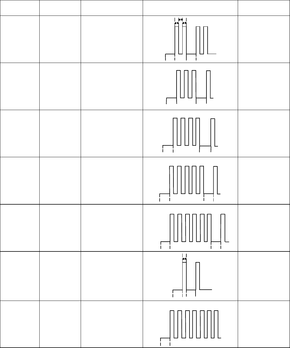
Table 2--1 System Self--diagnostics Function (Ducted Remote)
Flashes Error Codes
(Priority) Error Contents
(Malfunction) Display Pattern Allowed Modes
21ROOM AIR THERM-
ISTOR FAILURE
3sec
.3sec
.
0.5 sec.
(Twice) FAN Mode
3 2 INDOOR COIL
THERMISTOR FAIL-
URE
3sec
.3sec.
0.5 sec (3
Times) FAN Mode
FURNACE Mode
4 3 OUTDOOR COIL
THERMISTOR
FAILURE
3sec. 3sec
.
0.5 sec. (4
Times) FAN Mode
FURNACE Mode
5 4 COMPRESSOR
DRIVE
MALFUNCTION
3sec
.3sec
.
0.5 sec. (5
Times) FAN Mode
FURNACE Mode
6 5 REVERSING VALVE
DRIVE MAL--
FUNCTION
3sec
.
0.5 sec.
(6Times)
3sec
.
FAN Mode
FURNACE Mode
16DISCHARGE AIR
THERMISTOR FAIL-
URE
3sec
.3sec
.
0.5 sec.
(Once) FAN Mode
FURNACE Mode
Continuous 7THERMISTOR
WIRING WRONG
(only in cooling
test mode)
3sec
.
0.5 sec. (Continu-
ous) FAN Mode
NOTE:
If more than two errors occur, the highest ranked code is displayed. If the highest ranked error is cleared, the
next highest ranked error code is displayed.
T--298
3-1
SECTION 3
SERVICE AND MAINTENANCE
3.1 PREVENTATIVE MAINTENANCE
Cleaning--Clean evaporator coil and condenser coil.
Hold flashlight behind coil to see if all spaces are clear.
Dust accumulation obstructs or reduces airflow and
results in loss of cooling capacity. Both coils may be
vacuumed when dry. Coils may also be brushed with a
stiff brush and then blown out with compressed air.
Thoroughly clean base pan, motors, fan wheels, and
other components.
Clean cover and ceiling grill. Mild detergents reduce
electrostatic charges on plastic sections of the grill and
are good cleaners.
CAUTION
Do not use carbon tetrachloride, solvents,
or waxes containing solvents to clean plas-
tic sections.
Painting--Paint any parts that show evidence of rust
with a good rust--prevention paint.
Wiring-- Check all wiring for deterioration and all
electrical contacts for tightness or corrosion.
Mounting--Make sure unit is secure on roof according
to installation instructions provided in Owner’s Guide.
Checkfans toinsure thattheyarecorrectlypositionedin
the center of the orifice, and tight on the shaft.
Leaks--Check any connections that show evidence of
oil or leaks. When unit is properly installed (refer to
Owner’s Guide) check gaskets for possible air leakage.
Controls--Check unit to ensure all controls are
functioning correctly and unit operation is normal.
Vibrations can cause unwanted noise.
NOTE
Check to ensure that piping is not vibrating
against side of the unit.
NOTE
For proper cleaning and flushing, use a UL
approved refrigerant recovery/recycling
system.
NOTE
Refrigerant removal must always include
recovering the refrigerant, not allowing it to
escape to the atmosphere.
3.2 SERVICE -- GENERAL
General Notes—These Service Instructions are
provided to assist the trained and qualified Carrier
service technician in repairing or replacing components
of the AirV units.
WARNING
Before working on the unit be sure to first
disconnect all electric power to the unit to
avoid thepossibilityof electrical shockand
personal injury. Before disconnecting, dis-
charge capacitors by shorting across the
capacitors terminals (Refer to paragraph
3.5.8)
WARNING
Shield coils with cardboard to protect
hands against injury from sharp metal
edgeswhen removing compressor and oth-
er components.
3.3 CEILING UNIT -- FREE BLOW SYSTEMS
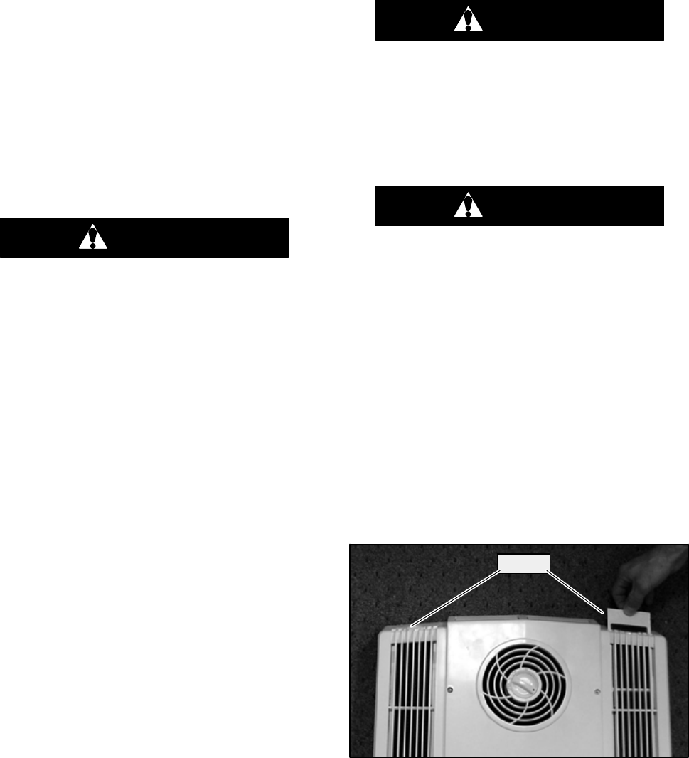
3.3.1 Filter Removal
The filters (Figure 3-1) are located in the ceiling grill. To
remove the filters, do the following:
a. Grasp the edge of the filter at recess in the end of the
ceiling grill.
b. Pull filter completely out of the filter slot.
c. Vacuum filter or wash filter in luke--warm water.
Shake off excess water and dry thoroughly.
d. Replace filter by sliding the filter into the filter slot in
the ceiling grill until the filter frame is flush with the in-
terior grill.
Filters
Figure 3-1 Filter Removal -- Free Blow
3.3.2 Ceiling Grill Removal
To remove the ceiling grill (Figure 3-2) do the following:
a. Before working on unit place the master switch in the
OFF position and disconnect all electrical power.
b. Remove 4 screws located on the ceiling grill, making
sure to support the weight of the grill.
c. Lower the ceiling grill from the ceiling panel.
T--298 3-2
d. To replace the grill, place the grill up against the ceil-
ing paneland alignthescrew holesin thegrill withthe
ceiling panel.
e. Replace 4 screws.
Mounting
Screws
Figure 3-2 Ceiling Grill -- Free Blow
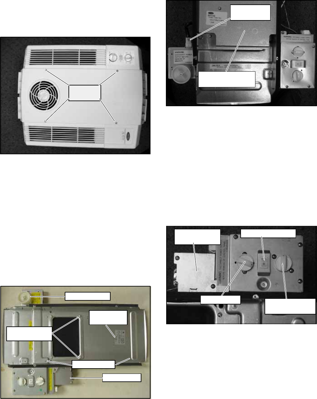
3.3.3 Ceiling Panel Removal
To remove the ceiling panel (Figure 3-3) do the
following:
a. Remove the ceiling grill. (Refer to paragraph 3.3.2.)
b. Remove 5 screws securing the duct plate to the ceil-
ing panel.
c. Remove 4 mounting bolts making sure to support the
weight of the ceiling panel.
d. Disconnect the unit harnesses and main power wires
from the ceiling panel.
e. Lower the ceiling panel from the air conditioningunit.
f. Reverse above procedure for reassembly.
Junction Box
Duct Plate &
Mounting Holes
Serial/Model
Number Tag
Air Sweep Cam
Mounting Bolts
Figure 3-3 Ceiling Panel Assembly
Heater Assembly
Option
Heat Strip
Connection
Figure 3-4 Ceiling Panel With Heat Option
3.3.4 Master Control Switch
To remove the master control switch, do the following:
a. Remove ceiling grill. (Refer to paragraph 3.3.2.)
b. Remove 5 screws that secure the control assembly
(Item 2, Figure 1-3) to the control box cover.
c. Remove the master control switch knob by grabbing
the outside edge of the knob and pulling it off of the
switch stem.
d. Remove 2 screws securing the master control switch
to the control assembly.
e. Carefully disconnect wires from the master control
switch. Label wires to aid in reassembly.
f. Reverse above procedure for reassembly.
Air Sweep Switch
Master Control
Switch
Thermostat
Junction Box
With Cover
Figure 3-5 Control Box Assembly -- Free Blow
3.3.5 Air Sweep Switch Removal
To remove the air sweep switch, do the following:
a. Remove ceiling grill. (Refer to paragraph 3.3.2.)
b. Remove 5 screws securing the control assembly
(Item 2, Figure 1-3) to the control box cover.
c. Disconnect wires from the air sweep switch.
d. Pinch tabs on either end of the switch and slide out of
lower control box cover.
e. Reverse above procedure for reassembly.
T--298
3-3
3.3.6 Indoor Thermostat Removal
To remove the indoor thermostat (Figure 3-6) do the
following:
a. Remove ceiling grille. (Refer to paragraph 3.3.2.)
b. Remove 5 screws securing the control assembly
(item 3, Figure 1-3) to the control box cover.
c. Remove the indoor thermostat knob by grabbing the
outside edge of the knob and pulling it off of the ther-
mostat stem.
d.Remove2screwsthatsecuretheindoorthermostatto
the lower control box cover.
e. Carefully disconnect the 2 wires from the indoor ther-
mostat.
f. Remove the sensing bulb from the plastic clip.
g. Carefully slide the sensing bulb through the rubber
grommet.
h. Remove the thermostat from the control assembly.
i. Reverse above procedure for reassembly.
Thermostat
Sensing Bulb
Figure 3-6 Indoor Thermostat
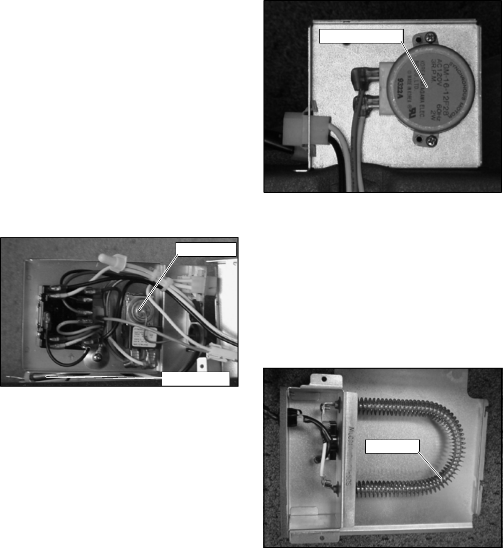
3.3.7 Air Sweep Removal
To remove the air sweep, do the following:
a. Remove ceiling grille. (Refer to paragraph 3.3.2.)
b. Remove cam (See Figure 3-3) from air sweep motor
shaft.
c. Remove 4 screws securing air sweep motor bracket
to the ceiling panel assembly.
d. Carefully disconnect air sweep motor wire termina-
tions.
e. Remove 2 screws securing air sweep motor
(Figure 3-7) to control box and remove motor.
f. Reverse above procedure for reassembly.
Air Sweep Motor
Figure 3-7 Air sweep motor
3.3.8 Heat Strip Assembly Removal
To remove the heat strip assembly (Figure 3-8) do the
following:
a. Remove ceiling grille. (Refer to paragraph 3.3.2.)
b. Unplug electrical connection at air sweep motor as-
sembly.
c. Remove two screws securing heat strip assembly to
the ceiling panel assembly.
d. Slide heat strip assembly away from air sweep motor
assembly and pull down, easing the the electrical
connection through the access hole.
e. Reverse the procedures for reassembly.
Heat Strip
Figure 3-8 Heat Strip Assembly
T--298 3-4
3.4 CEILING UNIT -- DUCTED SYSTEMS
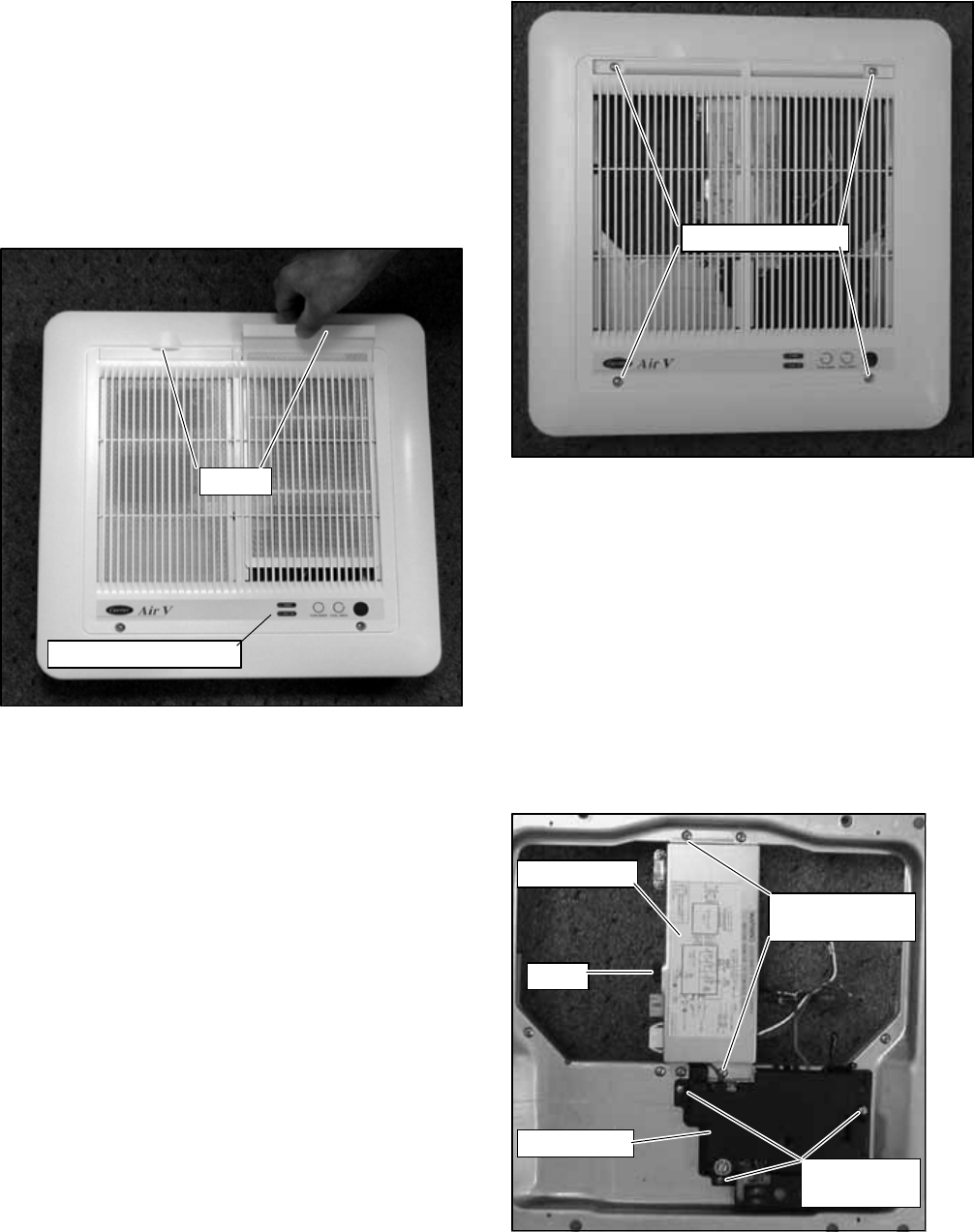
3.4.1 Filter Removal
The filters (Figure 3-9) are located in the ceiling grill. To
remove the filters, do the following:
a. Grasp the edge of the filter at recess in the end of the
ceiling grill.
b. Pull filter completely out of the filter slot.
c. Vacuum filter or wash filter in luke--warm water.
Shake off excess water and dry thoroughly.
d. Replace filter by sliding the filter into the filter slot in
the ceiling grill until the filter frame is flush with the in-
terior grill.
Filters
Operation Indicators
Figure 3-9 Filter Removal -- Ducted Unit
3.4.2 Ceiling Grill Removal
Toremovetheceilinggrill(Figure3--10)dothefollowing:
a. Before working on unit place the master switch in the
OFF position and disconnect all electrical power.
b. Remove filters (Refer to paragraph 3.4.1).
c. Remove 4 screws located on the ceiling grill, (twoare
under the filters)making sureto support the weight of
the grill.
d. Lower the ceiling grill from the ceiling panel.
e. To replace the grill, place the grill up against the ceil-
ing paneland alignthescrew holesin thegrill withthe
ceiling panel.
f. Replace 4 screws and 2 filters.
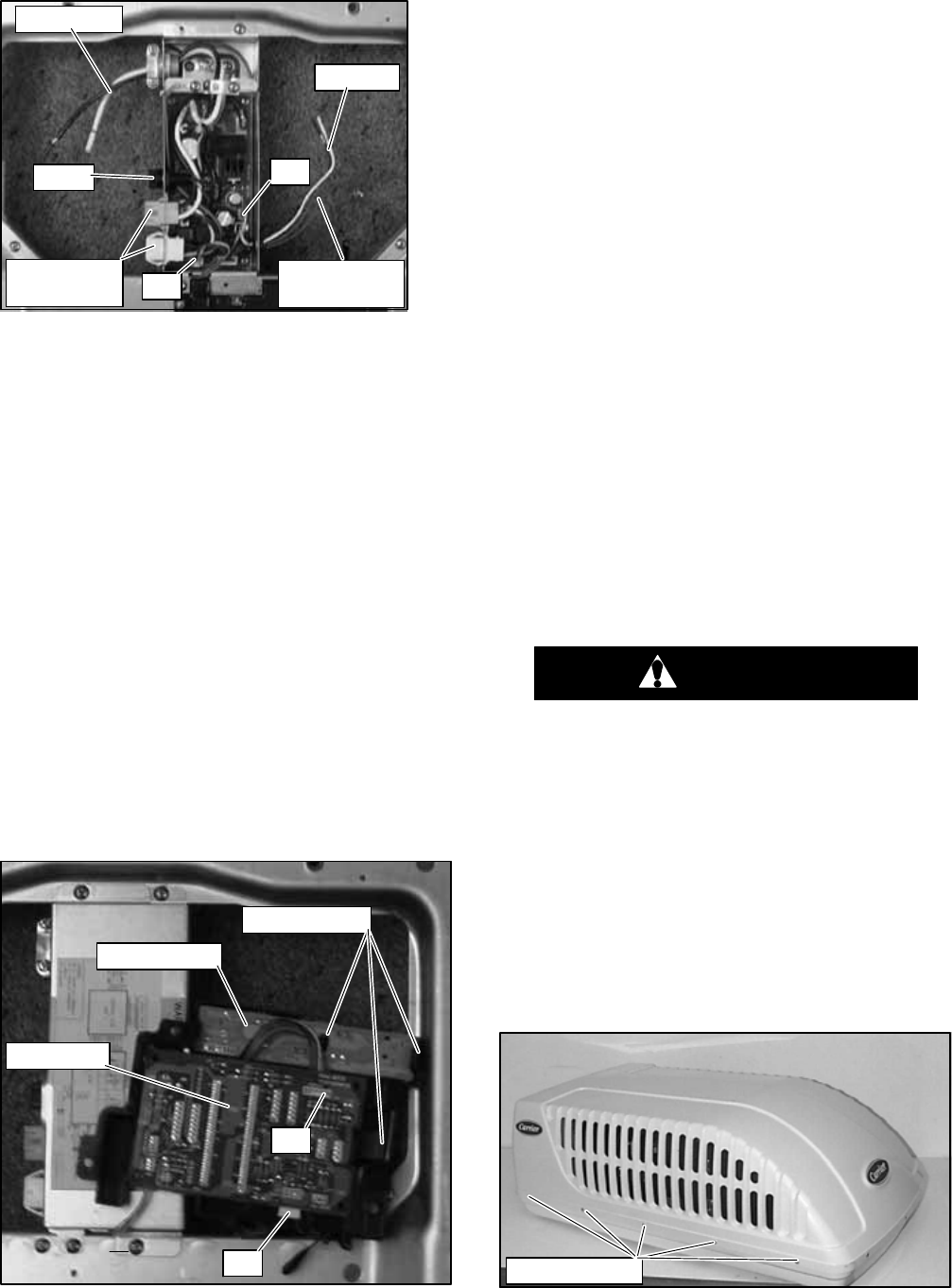
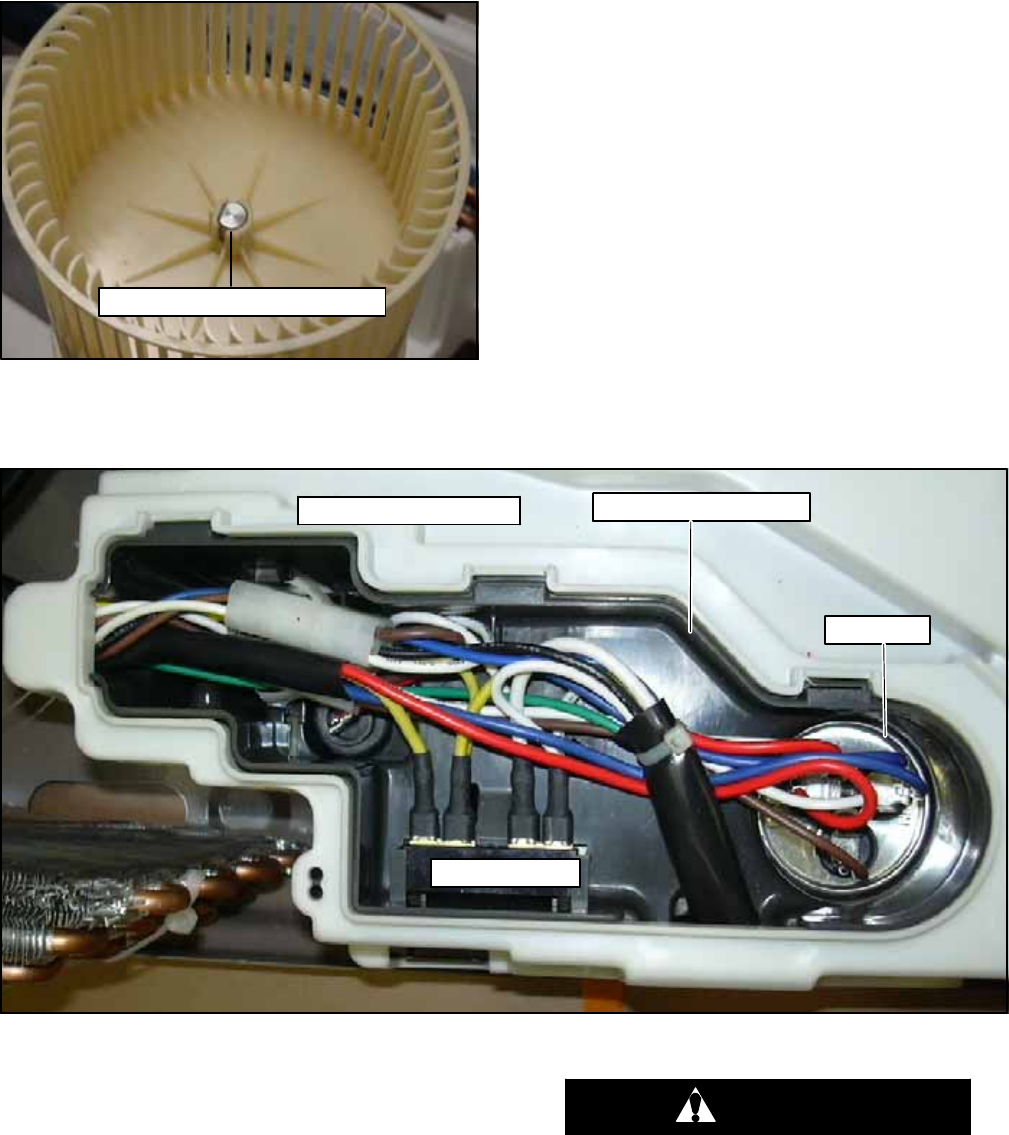
3.4.3 Control Box Assembly Removal
To remove the control box assembly (Figure 3-11 &
Figure 3-12) do the following:
a. Remove ceiling grill. Refer to paragraph 3.4.2.
b. Disconnect 115 volt (AC) and 12 volt (DC) power
wires.
c. Remove two screws securing control box cover to
control box assembly. See Figure 3-11.
d. Remove control box assembly cover.
Mounting Screws
Figure 3-10 Ceiling Grill -- Ducted
e. Disconnect blue furnace wires.
f. Unplug two connectors from upper unit.
g. Unplug DC power plug #1 (red/yellow/black wires)
SeeFigure3-12
h. Unplug relay signal plug #2 (brown/red/orange/
yellow wires). See Figure 3-12
i. While supporting control box assembly remove two
screws securing control box assembly to ducted ceil-
ing unit.
j. Pullcontrolboxassemblyfromtheductedceilingunit.
k. Reverse above procedure to reassemble.
Control Box
PCB Cover
Fuse
Control Box
Cover Screws
PCB Cover
Screws
Figure 3-11 Control Box & PCB Cover
T--298
3-5
115V AC
12V DC
Fuse
Upper Unit
Connectors Furnace
Wires (blue)
#1
#2
Figure 3-12 Control Box Assembly -- Ducted
3.4.4 Main PCB Board Removal
To remove the Main PCB board (Figure 3-13) do the
following:
a. Remove ceiling grill. Refer to paragraph 3.4.2.
b. Remove three screws securing the PCB cover to the
ducted ceiling unit.
c. Carefully turn over the PCB cover exposing the PCB
main and the PCB display assemblies.
d. GentlypushholdingclipawayfromPCBmainassem-
bly.
e. Lift PCB main assembly from PCB cover assembly.
f. Unplug display wiring plug #4. Figure 3-13
g. Unplug thermistor/thermostat wiring plug #3.
Figure 3-13
h. Unplug power wiring plug #1. Figure 3-12
i. Unplug signal wiring plug #2. Figure 3-12
j. Reverse above procedures for reassembly.
Holding Clips
PCB Display
PCB Main
#3
#4
Figure 3-13 Main/Display PCB’s
3.4.5 PCB Display Removal
To remove the PCB display assembly (Figure 3-13) do
the following.
a. Remove ceiling grill. Refer to paragraph 3.4.2.
b. Push large clip away from PCB display assembly.
c. Push center clip towards large clip.
d. Pull PCB display assembly from PCB cover.
e. Unplug display wiring from PCB main assembly.
f. Reverse above procedures of reassembly.
3.4.6 Fuse Removal
To remove the fuse (Figure 3-11) do the following:
a. Remove ceiling grill. Refer to paragraph 3.4.2.
b. Turnfuseholderindirectionofarrow(counter--clock--
wise).
c. Pull fuse from fuse holder.
d. Test and/or replace.
e. Reverse above procedures for reassembly.
3.5 SERVICE -- UPPER UNIT -- STANDARD,
HC&HP
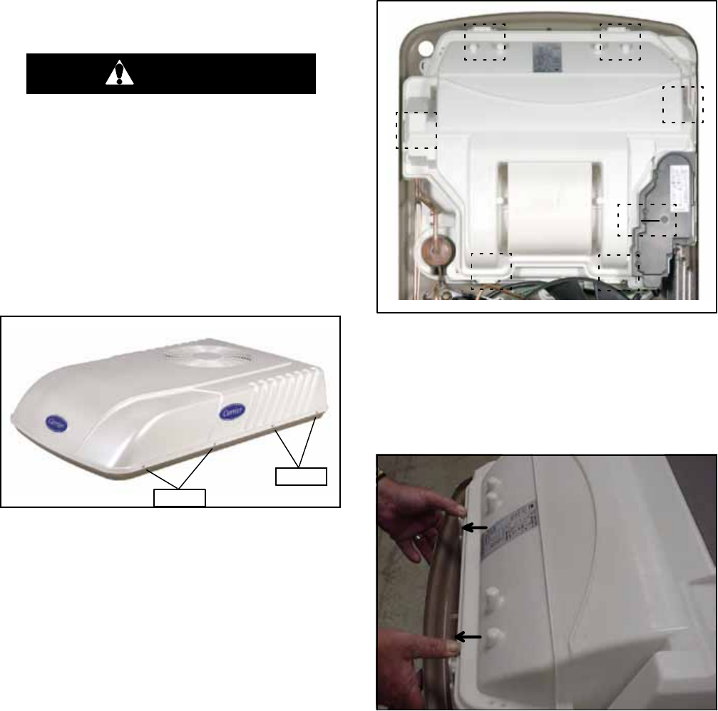
3.5.1 Exterior Cover Removal
CAUTION
Coilfinsaresharp.Usecarewhenremoving
the cover form the base pan to avoid per-
sonal injury.
To remove the exterior cover, do the following:
a. Before working on unit place the master switch in the
OFF position and disconnect all electrical power.
b. Remove 15 screws securing the unit cover to the
base pan assembly. See Figure 3-14.
c. Carefully lifttheexteriorcover offof the unit basepan
assembly.
d. Reverse above procedure for reassembly.
Cover Screws
Figure 3-14 Cover Assembly -- Standard
T--298 3-6
3.5.2 Compressor Replacement
Observe the same procedures for rotary compressors
as for reciprocating compressors.
a. Follow all safety codes. Reminder: use protective
goggles, work gloves, and water soaked quenching
cloth.
b. Remove exterior cover. refer toparagraph 3.5.1.Dis-
connect all wiring from the compressor.
c. Apply field--supplied, line--tap--valves to the suction
and discharge lines as close to the compressor as
possible.
d. Recovertherefrigerantchargefromtheunit.Afterre-
covering, cut the discharge and suction line process
tubes below the tube crimps. If you choose a good
tubing location for cutting the refrigeration lines ini-
tially, the location is easily accessible when making
the final joints.
WARNING
Oil vapor in piping stubs can ignite from
torch flame and cause serious injury. Exer-
cise extreme care when brazing, and keep
brazing cloth and fire extinguisher handy
for emergency use.
e. Connect anitrogensupplytotheunit atoneof theline
--tap--valve connectors (5--psig maximum flow), leav-
ing the other connector open to the atmosphere.
Braze angle valves with stubs to each process tube.
f. Remove compressor from unit (3 bolts).
g. Remove line--tap--valves from suction anddischarge
lines.Carefullybrazetheholes closedfrom wherethe
line--tap--valves were removed.
h. Cleansystem:addorreplaceliquidlinefilterdrier.For
proper cleaning and flushing use a UL approved re-
frigerant recycling system.
i. Install new compressor and braze into place with
field--supplied copper slip couplings.
j.Connect wiring: replace wire terminals if necessary.
k. Proceed with evacuation and charging (15.9 OZ. --
.45 KG R22). Pinch off lines whereangle valves were
added. Cut off angle valves above pinch--off , and
braze tubes.
l. Start up unit.
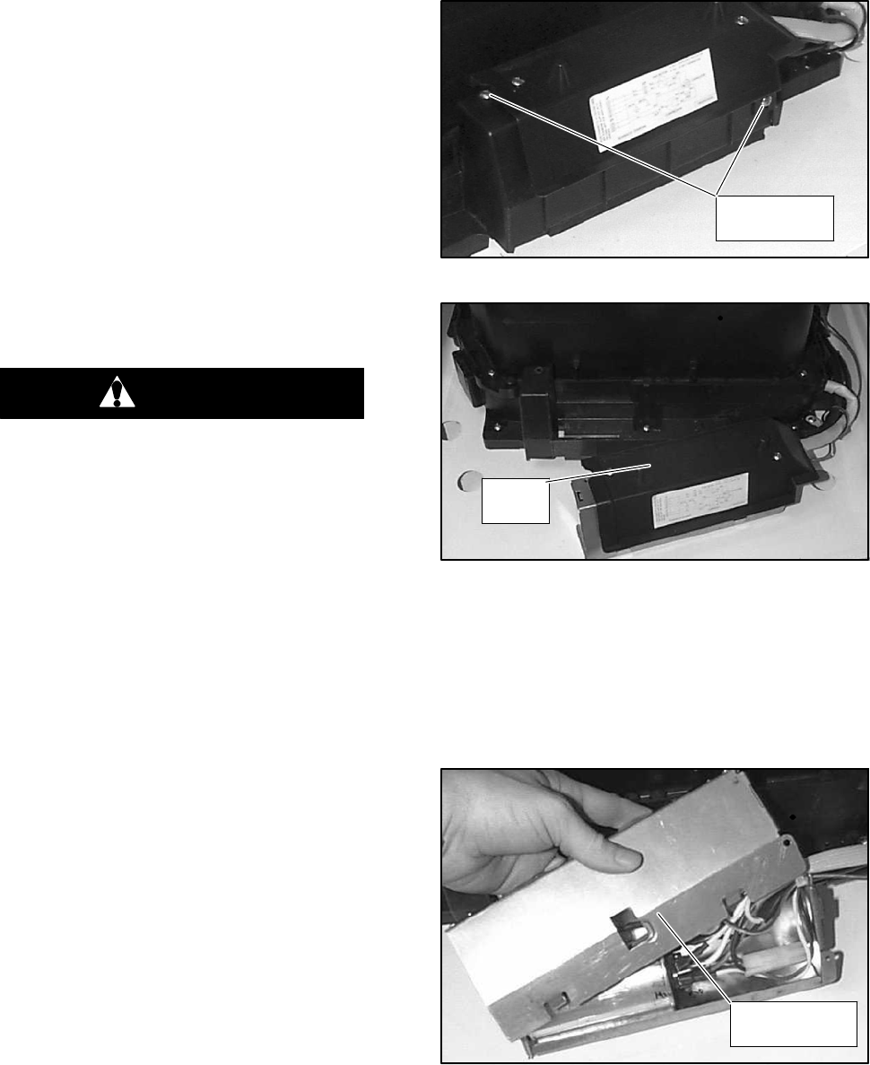
3.5.3 Control Box Assembly Removal
To remove the control box assembly, do the following:
a. Removeexterior cover assembly. Refertoparagraph
3.5.1.
b. Remove 2 screws securing control box assembly to
the lower scroll assembly. (SeeFigure 3-15.)
Control Box
Screws
Figure 3-15 Control Box
Water
Cover
Figure 3-16 Control Box Removal
c. Slide control box out of the lower scroll assembly.
(See Figure 3-16.)
d. To open control box remove 2 screws securing the
water cover to the control box cover.
e. Gently lift the water cover off of the control box. (See
Figure 3-17.)
f. Reverse above procedure for reassembly.
Control Box
Cover
Figure 3-17 Water Cover Removal
T--298
3-7
3.5.4 Upper Scroll Assembly Removal
a. Removeexterior cover assembly. Refertoparagraph
3.5.1.
b. Remove 4 screws securing upper scroll assembly to
the lower scroll assembly. (See Figure 3-18)
c. Gently pry 4 snap clips open and lift the upper scroll
assembly off of the lower scroll assembly.
d. Reverse above procedure for reassembly.
Screws
4 Places
Snap Clip
4 Places
Figure 3-18 Upper Scroll Assembly
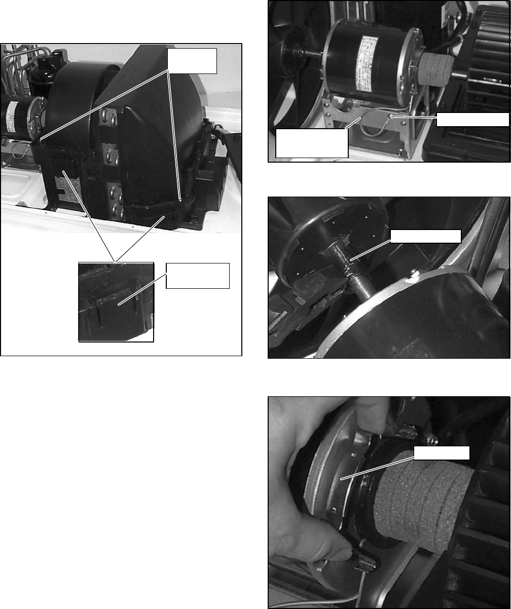
3.5.5 Motor Assembly and Condenser Fan
Removal
a. Removeexterior cover assembly. Refertoparagraph
3.5.1.
b. Remove control box assembly. Refer to paragraph
3.5.3.
c. Remove upper scroll assembly. Refer to paragraph
3.5.4.
d. Remove 4 screws securing the condenser cover to
the condenser orifice. (See Figure 3-24.)
e. Carefully disconnect motor wire terminations from
within the control box.
f. Remove 1 screw securing the motor ground lead to
the motor bracket assembly. (See Figure 3-19)
g. Using flat--nosed pliers, depress the motor spring
clamp and slide it off of the condenser fan (See
Figure 3-20).
h. Liftandslidemotortowardsevaporatorcoiltoremove
condenser fan from the motor shaft.
i. Remove condenser fan from motor shaft and lift fan
out through the top of the condenser orifice. (See
Figure 3-22)
j. Remove motor assembly.
k.Reverse above procedure for reassembly.
Motor Ground
Lead
Ground screw
Figure 3-19 Motor Assembly
Spring Clamp
Figure 3-20 Spring Clamp Removal
Motor Clip
Figure 3-21 Motor Clip Removal
T--298 3-8
Condenser Fan
Figure 3-22 Condenser Fan Removal
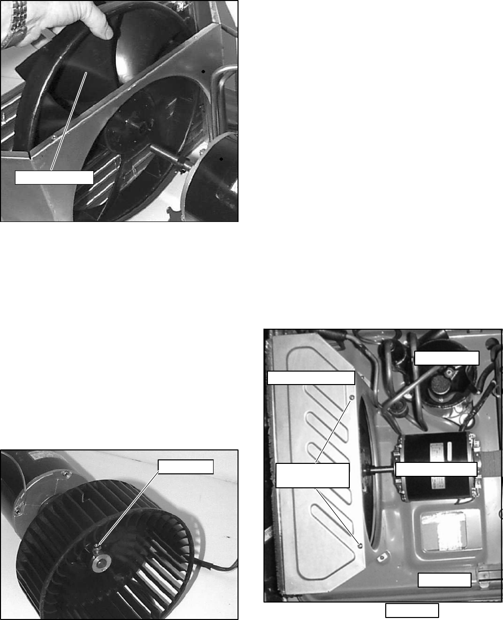
3.5.6 Evaporator Blower Wheel Adjustment or
Removal
a. Remove exterior cover assembly. Refer to Exterior
Cover Assembly Removal instructions 3.5.1
b. Remove control box assembly. Refer to Control Box
Assembly Removal instructions 3.5.3
c. Remove upper scroll assembly. Referto Upper Scroll
Assembly Removal instructions 3.5.4
d. Loosen motor assembly. Refer to Motor Assembly
Removal instructions 3.5.5.
e. Mark shaft at a point where wheel hub and motor
shaft meet to aid in reassembly.(See Figure 3-23.)
f. Remove 1 set screw holding the blower wheel to the
motor shaft. (See Figure 3-23)
g. Slide off blower wheel from motor shaft
h. Reverse above procedure for reassembly.
Set Screw
Figure 3-23 Blower Wheel
3.5.7 Air Handling System Removal
a. Removeexterior cover assembly. Refertoparagraph
3.5.1.
b. Remove control box assembly. Refer to paragraph
3.5.3.
c. Remove upper scroll assembly. Refer to paragraph
3.5.4.
d. Remove motor assembly. Refer to paragraph 3.5.5.
e. Remove 8 screws securing lower scroll assembly to
the base pan assembly.
f. Remove 1screw from clamp securing suction tubeto
the base pan assembly.
g. Remove 3 nuts securing the compressor to the base
pan assembly.
h. Remove 2 screws securing the condenser orifice to
the base pan assembly.
i. Remove 2 screws securing the condenser coil as-
sembly to the base pan assembly.
j. Carefully lift the entire assembly off of the base pan
assembly.
k. Reverse the above procedure for reassembly, ensur-
ing that the airhandling system is positioned correct-
ly. Tighten all screws.
Condenser Cover
Condenser
Cover Screws
Compressor
Motor Assembly
Base Pan
Base Pan
Figure 3-24 Condenser With Motor Assembly &
Compressor
T--298
3-9
3.5.8 Capacitor Troubleshooting
WARNING
Disconnect power to the AirV unit before
checking the capacitor.
To test capacitor to determine if good, open or shorted,
an ohm meter can be used. To determine a capacitor’s
capacitance, a capacitor meter is required.
Capacitors showing signs of leaks or bulging should be
replaced immediately.
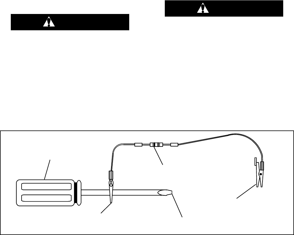
3.5.9 Capacitor Testing and Replacement
Capacitors must be discharged properly before testing.
a. Place a 20,000 ohm, 2 watt resistor across the termi-
nals of the capacitor for approximately 30 seconds
(See Figure 3-25 for a suggested tool).
WARNING
Do not touch the metal of the screwdriver
when discharging the capacitor. You could
receive a shock.
b. After the capacitor has been dischargedand all wires
removed from the capacitor terminals, use an ohm--
meter to test its resistance.
c. Set the scale to R x 1K or 10K ohm and place the
ohmmeter leads across the capacitor terminals.
d. Iftheohmmeterfirstreads0, thenrises towardinfinity
or some higher resistance, the capacitor is good.
e. If the ohmmeter goes to 0 or a low resistance and
stays there, the capacitor is shorted and needs to be
replaced.
f. If the ohmmeter reads infinity (OL) the capacitor is
open and needs to be replaced.
CLIP TO
SCREWDRIVER TOUCH TO CAPACITOR TERMINALS
TO DISCHARGE CAPACITOR
20,000 -- OHM
2 -- WATT RESISTOR
INSULATED SCREWDRIVER
ATTACH TO CLEAN UNPAINTED
METAL PART OF UNIT FRAME
Figure 3-25 Set--Up For Discharging a Capacitor
3.5.10 Positive Temperature Coefficient Thermister
(PTC) (Start Thermistor) Troubleshooting
a. Disconnect power from the AirV unit.
b. Disconnect the wires to the PTC.
c. Using an ohm meter, check for continuity across the
PTC.
If thePTCdoesnot havecontinuity, itmust bereplaced.
If continuity exists, reconnect the wires to the PTC.
d. Reconnect power to the AirV unit.
e. Turn on the AirV unit to start.
f. Use a clamp--on amp probe to monitor the amp draw
of the compressor during its start--up.
When the compressor starts, an amp draw will be
indicated for almost a second.
If no amp draw is indicated or if the amp draw occursfor
much longer than a second, the PTC is defective and
must be replaced.
3.5.11 Line Voltage -- 10%
Line voltage should be checked during peak electrical
load periods.
WiththeAirV unit onandthecompressoroperating,use
a voltmeter to check the voltage being supplied to the
AirV unit. The voltage must be within 10% of the units
required voltage. A voltage drop greater than 10% will
cause a premature compressor failure and needs to be
corrected immediately.
T--298 3-10
3.6 SERVICE -- UPPER UNIT -- LOW PROFILE
3.6.1 Exterior Cover Removal
CAUTION
Coilfinsaresharp.Usecarewhenremoving
the cover form the base pan to avoid per-
sonal injury.
To remove the exterior cover, do the following:
a. Before working on unit place the master switch in the
OFF position and disconnect all electrical power.
b. Remove (8) screws securing the unit cover to the
base pan assembly. See Figure 3-26.
c. Carefully lifttheexteriorcover offof the unit basepan
assembly.
d. Reverse above procedure for reassembly.
Screws
Screws
Figure 3-26 Cover Assembly -- Low Profile
3.6.2 Upper Scroll Assembly Removal
To remove the upper scroll assembly, do the following:
a. Removeexterior cover assembly. Refertoparagraph
3.6.1.
b. Releasethe(2)front,(2)rear,(1)leftsideand(1)right
sidelockingtabs (SeeFigure 3-27)bypullingbackon
the tabs (See Figure 3-28).
c. Remove the screw (1) from the control box cover
(See Figure 3-27).
d. With all (6) locking tabs released and control box
screw removed, lift the upper scroll assembly off of
the lower scroll assembly.
e. Reverse above procedure for reassembly. Ensure all
(6) locking tabs snap shut & lock.
b. b.
b.
b.
b. b.
c.
Figure 3-27 Upper Scroll Assembly
Locking Tabs (b.) & Screw Locations (c.)
Figure 3-28 Upper Scroll Assembly
Keeper Tab Release
T--298
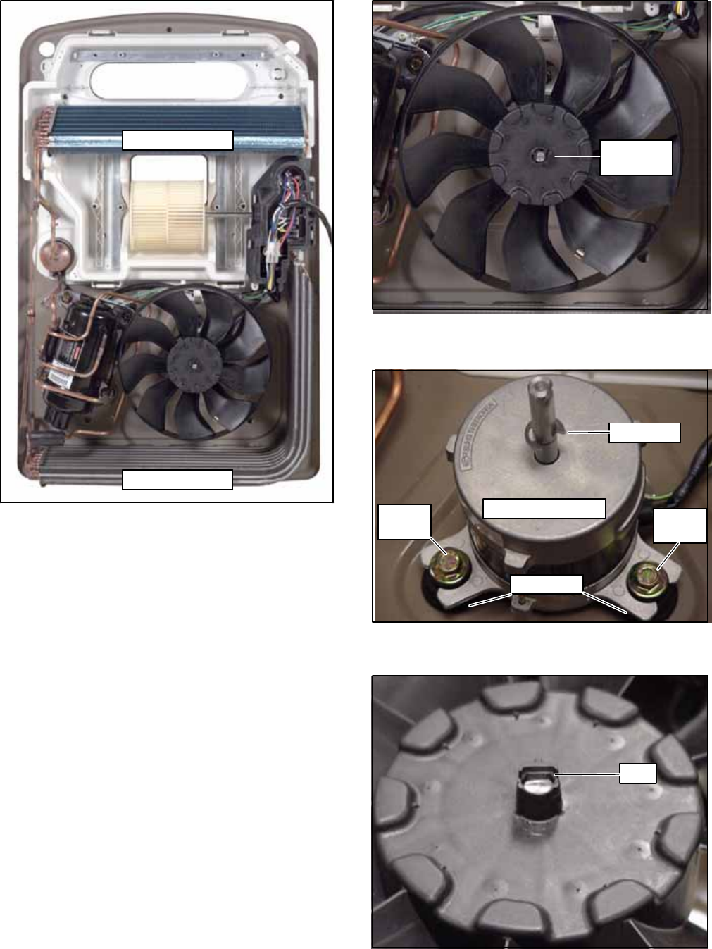
3-11
Evaporator Coil
Condenser Coil
Figure 3-29 Upper Scroll & Control Box
Cover Removed
3.6.3 Condenser Fan Assembly Removal
To remove condenser fan assembly, do the following:
a. Perform steps outlined in Section 3.6.2.
b. Depress and remove Retaining Ring (See
Figure 3-30).
c. Using both hands, carefully pull up on fan assembly
until it is free of the motor shaft.
d. When replacing the fan assembly make sure the fan
assembly is against the stop on the shaft (See
Figure 3-31)
e. Push back on tab to allow fan assembly to rest
against stop (See Figure 3-32). Fan assembly will
now be flush with the end of the motor shaft.
f. Reverse above procedure for reassembly.
Retaining
Ring
Figure 3-30 Condenser Fan Assembly
& Retaining Ring
Fan Stop
Condenser Motor
13MM
Bolt 13MM
Bolt
Grommet
Figure 3-31 Condenser Fan Motor
& Fan Assembly Stop
Tab
Figure 3-32 Condenser Fan Motor
& Fan Assembly Tab
T--298 3-12
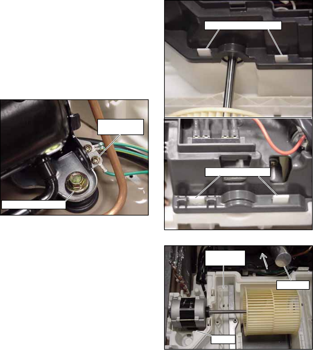
3.6.4 Condenser Motor Removal
To remove condenser fan motor, do the following:
a. Perform steps outlined in Section 3.6.2.
b. Remove (3) 13MM bolts (See Figure 3-31).
c. Remove (3) Grommets. Inspect, replace or reuse.
d. Cut Tie--Wraps & discard (2 locations). When re-
assembling, tie--wrap at same 2 locations.
e. Remove ground wire from compressor bracket (See
Figure 3-33).
f. Un--plug (yellow/brown/white) from control box as-
sembly.
g. Reverse above procedure for reassembly.
Cond. Motor
Ground Screw
Comp. Mounting Bolt
Figure 3-33 Condenser Motor Ground
3.6.5 Evaporator Motor/Blower Assembly
Removal
To remove the evaporator motor, do the following:
a. Perform steps outlined in Section 3.6.2.
b. Pull back on and release the (4) locking tabs. There
are 2 on each side of the control box assembly. (See
Figure 3-34).
c. Lift control box assembly from lower scroll assembly,
exposing evaporator motor.
d. Un--plug (black/blue/white/brown) evaporator motor
from control box assembly.
e. Remove ground wire (green/yellow) from motor
housing.
f. Lift motor/blower assembly from lower scroll assem-
bly cradle.
g. Carefullyremovethe blower wheelfrom the evapora-
tor motor shaft by pushing out from the motor side.
Blower Side Locking Tabs
Outside Locking Tabs
Figure 3-34 Evaporator Motor Locking Tabs
Cradle
Lower Scroll
Assembly
Capacitor
Figure 3-35 Evaporator Motor/Blower Assembly
In Cradle
T--298
3-13
NOTE
When reassembling the blower wheel on to
the motor shaft ensure that the blower
wheel is flush with the end of the motor
shaft (SeeFigure 3-36).
h. Reverse above procedure for reassembly.
Wheel Flush With Motor Shaft
Figure 3-36 Evaporator Blower Wheel
(Flush With End Of Motor Shaft)
NOTE
When placing the evaporator motor/blower
assembly back into the lower scroll assem-
bly cradle, make sure that the assembly is
seated securely in the cradle.
(See Figure 3-35).
3.6.6 Compressor Replacement
Perform the procedures outlined in Section 3.5.2
There are 4 bolts with the Low Profile Compressor.
The system charge for the Low Profile unit is 16.9 OZ.
3.6.7 Capacitor Removal
To remove the capacitor, do the following:
a. Perform steps a., b. & c. as outlinedin Section3.6.5.
b. Perform steps outlined in Sections 3.5.8 & 3.5.9.
c. The Low Profile Capacitor is removed from the con-
trol box assembly by pushing on the capacitor from
under the control box assembly (See Figure 3-35).
Capacitor
Control Box Assembly
Terminal Block
Upper Scroll Assembly
Figure 3-37 Control Box Assembly With Capacitor
3.6.8 Remote Control (Fahrenheit to Celsius)
All Remote Control Assemblies in the United States are
pre--set to display in Fahrenheit degrees (see
Figure 3-38). To change from a Fahrenheit display to a
Celsius display do the following:
CAUTION
The change from Fahrenheit to Celsius will
bepermanent. It cannotbechangedbackto
Fahrenheit.
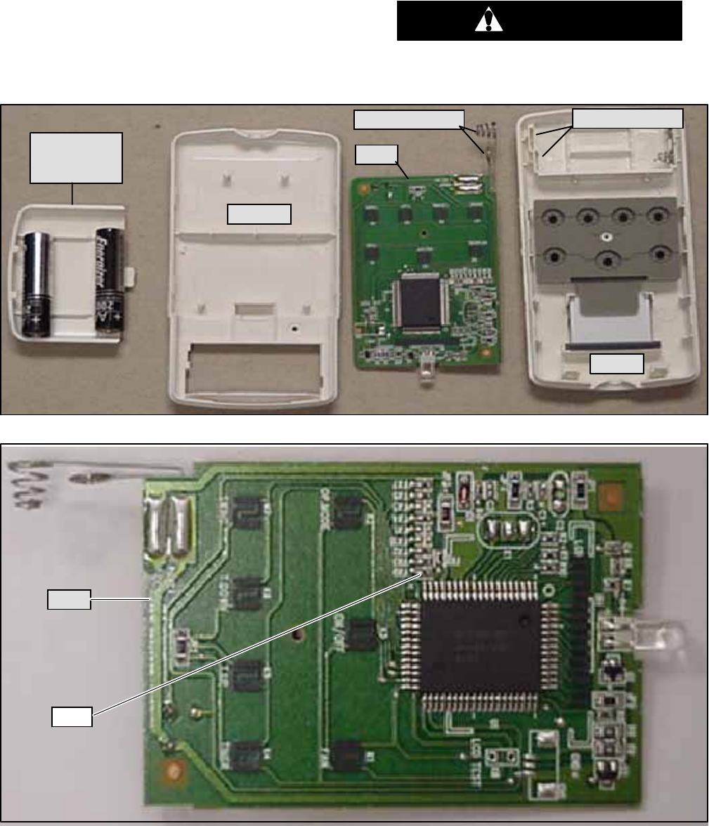
T--298 3-14
a. Remove the batteries from the remote control.
b. Carefullyremovetheremotecoverbyinsertinganar-
row flat object between the cover and remote body
and prying apart.
c. Remove the brass screw holding the PCB in place.
d. Carefully remove the PCB board from the remote
body, making sure the battery springs release from
their holders.
e. Locate FR9 on the PCB board (see Figure 3-39).
f. Carefully cut the FR9 jumper wire.
g. Reverse above procedure for reassembly.
CAUTION
When re--assembling, ensure the battery
springs are correctly placed in the battery
spring holders.
PCB
COVER
BODY
BATTERIES
&
COVER
Battery Springs Spring Holders
Figure 3-38 Remote Control Components
FR9
PCB
Figure 3-39 Remote Control PCB (FR9 Location)

T--298
3-15
3.7 THERMOSTAT INSTALLATION AND START--
UP INSTRUCTIONS (WALL MOUNTED)
3.7.1 Introduction
The thermostat is a wall mounted, low--voltage
thermostat which maintains room temperature by
controlling the operation of a heating and air
conditioning system. Batteries are not required;
temperature and mode settings are preserved with the
power off.
CAUTION
Improperwiringorinstallationmaydamage
thermostat. Wiring must conform to local
and national electrical codes.
WARNING
Before installing thermostat, turn off all
power to unit. There may be more than one
power disconnect. Electrical shock can
cause personal injury or death.
3.7.2 Installation
NOTE
Readallinstructionsbeforestartingtheinstalla-
tion.
NOTE
The thermostat requires no batteries. The ther-
mostat is not a power stealing device and
MUST have both R and C connected.
3.7.3 Thermostat Location
The thermostat should be mounted:
Approximately 5 foot (1.5m) from the floor.
Close to or in a frequently used room, preferably on
an inside partitioning wall.
On a section of wall without pipes or duct work.
The thermostat should NOT be mounted:
Closetoawindow,oranoutsidewall,ornextto adoor
leading to the outside.
Exposedtodirectlightandheatfromalamp,sun,fire-
place, or other temperature--radiating object which
may cause a false reading.
Close to or in direct airflow from supply registers and
return--air grilles.
In areas with poor air circulation, such as behind a
door or in an alcove.
3.7.4 Install Thermostat -- 12VDC
a. Turn off all power to unit.
b. If an existing thermostat is being replaced:
1.Remove existing thermostat from wall.
2.Disconnect wires from existing thermostat, one at
a time. Be careful not to allow wires to fall back into
the wall.
3.As each wire is disconnected, record wire color
and terminal marking.
4.Discard or recycle old thermostat.
NOTE
Mercuryisahazardouswasteandmustbedes-
posed of properly.
c. Seperate the front and back pieces of plastic.
d. Route thermostat wires through hole in back piece of
plastic. Level plastic against wall (for aesthetic value
only -- thermostat need not be leveled for proper op-
eration) and mark wall through 2 mounting holes.
e. Drill two 3/16 inch mounting holes in wall where
marked.
NOTE
Mounting holes on thermostat are designed to
fit on a horizontal J--Box.
f. Secureback plastictowallwith2anchors andscrews
provided,makingsureallwiresextendthroughholein
plastic.
g. Connect wires to proper terminal of the connector
block in the front piece of plastic.
h. Pusr any excess wire back into wall. Excess wire in-
side the thermostat plastic case can interfere with
proper air flow across the temperature sensor. Seal
hole in wall to prevent air leaks. Leaks can effect op-
eration.
i. Snap front and back pieces of plastic together.
j. Turn on power to the unit.
3.8 LCD DISPLAY
3.8.1 Cool Only Thermostat (Part No. 1110--421)
On power up, the LCD readout will display C (Cool
Only).
3.8.2 Heat/Cool Thermostat (Part No. 1110--420)
On power up, the LCD readout will display HC (Heat/
Cool).
3.9 SET THERMOSTAT CONFIGURATION
While in configuration mode, three option choices can be
made.
A-- Anticipator Value Adjustment
d-- Display Temperature Fahrenheit/Celcius Selection
oF -- Offset Adjustment For Room Temperature
3.9.1 Enter Configuration Mode
EnterandholdtheFANbuttonforapproximately 10sec-
ondsuntilroomtemperaturedisappears andthedisplay
reads A. You are now in the configuration mode.
T--298 3-16
NOTE
IftheFANbuttonispressedagainorif nobutton
is pressed for two minutes, the thermostat will
exit the configuration mode and return to nor-
mal operation. To re--enter the configuration
mode, the FAN button must be pressed and
held for 10 seconds again.
While in the configuration mode, the following options
are available:
A. ANTICIPATOR -- Value Adjustment
Thisadjustmentcontrolsthesensitivityandcyclerateof
the thermostst. Higher numbers decrease the
sensitivity and slow the cycle rate. Lower numbers
increase the sensitivity and increase the cycle rate.
However, a limiting feature will not allow more than 4
equipmentcyclesperhour,regardlessofsetting.Values
can range from 1 to 3. Factory default setting is 2. This
default selection will provide optimum performance in
nearlyallinstallations.Tryitfirst. Donotchangesettings
unless there is evidence of need to do so. Unlike
conventional anticipators, this setting is not determined
by current draw. There is no need to measure, know, or
compensate for current.
To Adjust:
a. Enter configuration mode (if not already there).
b. Use UP & DOWN buttons to display A.
c. Press MODE button once to display current value.
d. Use UP & DOWN buttons tomove between values.
e. Press MODE buttonto return to A.UP &DOWN
buttons now move between option choices A,d,oF or
press FAN button to exit configuration mode.
d. Fahrenheit/Celsius Selection
This selection operates the thermostat in either
Fahrenheit or Celsius.
To Select:
a. Enter configuration mode (if not already there).
b. Use UP & DOWN buttons to display d.
c. Press MODE button once to display current
selection of For C.
d. UseUP&DOWNbuttonstochangebetweenF&C.
e. Press MODE buttonto return to d.UP &DOWN
buttons now move between option choices; or press
FAN button to exit configuration mode.
oF. Room Temperature Offset Adjust Selection
The selected number is the number of degrees, plus or
minus, which will be added to the actual temperature.
The numbers can range between --5 and +5. Factory
default is 0. This adjusted value will be used as actual
temperature for both display and control action. The
effect is that a positive number selection will make the
room temperature lower, and vice versa. The
thermostat is calibrated within an accuracy of plus or
minus 2 degrees when shipped from the factory; this
adjustmentwill providethe best accuracy when set to o.
To Select:
a. Enter configuration mode (if not already there).
b. Use UP & DOWN buttons to display oF .
c. Press MODE button once to display offset value.
d. UseUP &DOWNbuttonstoselect avaluebetween
--5 and 5.
e. Press MODE buttonto return to oF.UP &DOWN
buttons now move between option choices; or press
FAN button to exit configuration mode.
3.10 CHECK THERMOSTAT OPERATION
3.10.1 Fan Operation (Cool Only)
1. Press FAN button, starting fan operation. FAN an-
nunciator turns on; Lo is displayed in the room tem-
perature area for 5 seconds indicating Fan Low
Speed.
2. Press FAN button, FAN annunciator remains on; Hi
is displayed in room temperature area for 5 seconds
indicating Fan High Speed.
3. Press FAN button, stopping fan operation. FAN an-
nunciator turns off.
3.10.2 Fan Operation (Heat/Cool)
1. Press FAN button, starting low fan (Lo) operation.
FAN annunciator turns on.
2. Press FAN button, starting high fan (Hi) operation.
FAN annunciator remains on.
3. Press FAN button, stopping fan operation. FAN an-
nunciator turns off.
3.10.3 Cooling Operation (Cool Only)
1. Press and release MODE button until COOL is dis-
played.
2. Press DOWN button until LCD readout reads 10 de-
grees below room temperature. Cooling and High
Fan system should begin to operate within 5 min-
utes.
3.10.4 Cooling Operation (Heat/Cool)
1. Press and release MODE button until COOL is dis-
played.
2. Press DOWN button until LCD readout reads 10 de-
grees below room temperature. Cooling and High
Fan system should begin to operate within 5 min-
utes.
3.10.5 Heating Operation (Heat/Cool)
1. Press and release MODE button until HEAT is dis-
played.
2. PressUPbuttonuntilLCDreadoutreads10degrees
above room temperature. Heating system should
begin to operate within 1 minute.
3.11 CHECK THERMOSTAT OPERATION
3.11.1 Temperature Display
The thermostat will display room temperature until the
UPor DOWNbuttonispressed.ThewordSETappears
when these buttons are pressed and the current set
point is displayed. If no buttons are pressed for 5
seconds, the display will change back to show room
temperature.
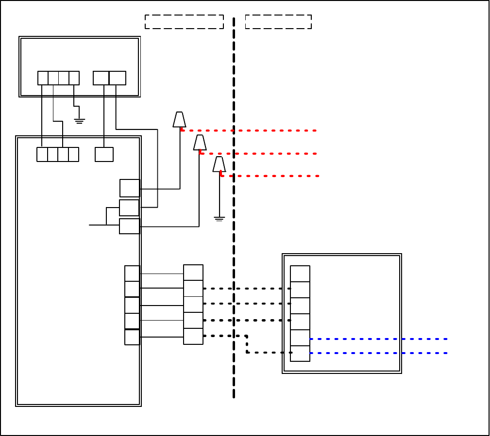
T--298
3-17
3.11.2 Timeguard Timer
A 3--minute timeguard is built into the thermostat
immediately upon power up, and any time the
compressor (output “Y”) turns off. The compressor will
notturnonuntilthetimeguardhasexpired.PressingUP
and FAN buttons simultaneously will override the
timeguard for 1 cycle.
3.11.3 Cycle Timer
In normal cooling (and heating) operation the
thermostat will not allow more than 4 equipment cycles
per hour (or 1 cycle every 15 minutes). Both the “Y”
(cooling) and “W” (heating) outputs have a 15--minute
timer that starts counting down when the output is
turned on, (e.g., if “Y” output is turned on for 9 minutes
and then satisfies, it cannout turn back on for another 6
minutes regardless of demand). However, pressing UP
and FAN buttons simultaneously or changing the set
point will override the timer for 1 cycle.
3.11.4 Minimum On Timer
Oncethe equipmenthas turnedon,itwillremainonfora
minimum of 2 minutes regardless of demand.However,
the equipment can turn off in less than 2 minutes if a
change in set point, or a changein mode occurs.
3.11.5 Error Messages
E4 will be displayed if the thermostat has an internal
memory failure. If E4 appears, replace the thermostat.
---- (two dashes) will be displayed if the thermostat
cannot properly read the room temperature. If ----
appears, replace the thermostat.
POWERBOX
ASSEMBLY
UPPER UNIT
1234 2 1
1234
1
2
3
4
5
L
N2
N1
W
Y
GH
GL
C
Y
GH
GL
R
C
COOL (Compressor)
FAN (High)
FAN (Low) 12VDC LowVoltage
Power Supply
CEILING UNIT
Motor Comp.
Factory Wiring Field Wiring
THERMOSTAT
J115V AC High Voltage
Power Supply
Figure 3-40 Wall Thermostat Wiring Diagram -- Cool Only Model
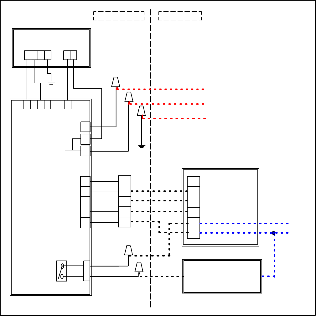
T--298 3-18
POWERBOX
ASSEMBLY
UPPER UNIT
1234 21
1234
1
2
3
4
5
1
2
L
N2
N1
W
Y
GH
GL
C
TB
Y
GH
GL
R
C
COOL (Compressor)
FAN (High)
FAN (Low) 12VDC LowVoltage
Power Supply
CEILING UNIT FURNACE
+ 12VDC 12 VDC (Gnd)
Motor Comp.
115V AC High Voltage
Power Supply
Factory Wiring Field Wiring
THERMOSTAT
J
Blue
Blue
Figure 3-41 Wall Thermostat Wiring Diagram -- Heat/Cool Model
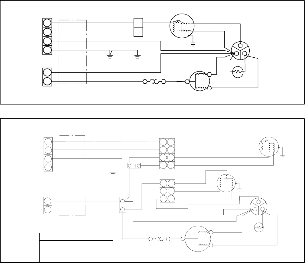
T--298
4-1
SECTION 4
WIRING SCHEMATICS
4.1 INTRODUCTION
This Section contains wiring schematics for the AirV units.
Figure 4--1 is the schematic for the standard upper unit assembly and it is applicable to all standard units.
Figure 4--2 is the schematic for the Low Profile upper unit assembly.
Figure 4--3 is the schematic for a free blow ceiling unit without heat while Figure 4--4 is a free blow unit with heat.
Figure 4--5 is for a ducted unit with microprocessor control.
Figure 4--6 is for an Upper Unit Heat Pump withfree blow application and Figure 4--7 is the matching free blow ceiling
unit.
Figure 4--8 is for the Upper Unit Heat Pump ducted application and Figure 4--9 is the matching ducted ceiling unit.
Notethattheductedunitshave115VACpower forthecomponentsand12VDCpower for themicroprocessorcontrol
system.
Figure 4--10is fortheductedorfreeblowapplicationthatusesawall--mountedthermostat,withorwithoutthefurnace
option.
Whereapplicable, diagramsthatdesignate115Volt, 60H, 1 Phase, arealsoavailable using220Volts,50H, 1Phase.
Most noteably Figure 4--1 and Figure 4--5.
4P 2P
2P
CFH
1
11
22
3
4
2
BLK
BLU
BLK
BLU
WHT
WHT
GRN/YEL
CONTROL
BOX EVAP.
GRN/YEL
GRN/YEL
WHTBRN
12
CAPACITOR
YEL
YEL
RED BLU
COMPRESSOR
R
C
S
FAN MOTOR
OVERLOAD PROTECTOR
RED
PTC
BLU
PLUG CONNECTS
TO CEILING UNIT
SEE FIG> 4--3
OR 4--4
(If Used)
Figure 4--1 Upper Unit Schematic -- Standard & HC
4P
2P
4P
CFH
BLK
BLU
BLK
BLU
WHT
GRN/YEL
GRN/YEL
WHT
WHT
WHT
BRN
BRN
1(3)
2
CAPACITOR
YEL
RED
OLP
(IF USED)
BLU
BLURED
COMPRESSOR
R
C
S
1
2
3
4
1
2
1
2
3
4
1
2
3
4
OLP: OVERLOAD PROTECTION
PTC: START THERMISTER
JTB: JOINT TERMINAL BLOCK
FMC: INDOOR FAN MOTOR CAPACITOR
PLUG CONNECTS TO CEILING UNIT.
SEE DIAGRAM SUPPLIED WITH
CEILING UNIT FOR ADDITIONAL
WIRING.
INDOOR FAN MOTOR
YEL
WHT
YEL
1
2
3
1
2
3
WHT
3P
YEL
BRN
FMC
YEL
WHT
BRN
OUTDOOR FAN MOTOR
PTC
(IF USED)
LEGEND
(UNIT -- 99--00468--10)
Figure 4--2 Upper Unit Schematic -- Low Profile
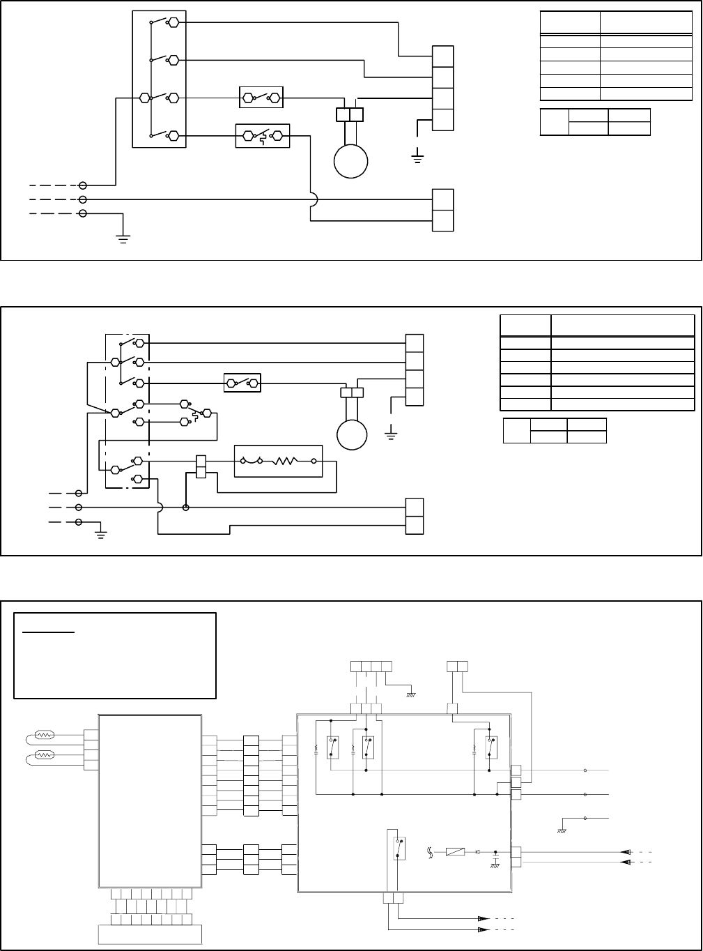
T--298 4-2
2P
GRN/YEL
ORN
WHT
WHT
ASM
PLUG CONNECTS TO UPPER UNIT.
SEE DIAGRAM SUPPLIED WITH
UPPER UNIT FOR ADDITIONAL WIRING.
4P
2P
1
1
2
3
4
2
{
ASW O (OFF)
I(ON)
2
2--1
SWITCH
POSITION CONTACTS MADE
HIGH FAN
LOW FAN
OFF
LOW COOL
1--4 . 1--6
1--2 . 1--6
NONE
1--2 . 1--6 . 1--8
1--4 . 1--6 . 1--8
HIGH COOL
ASM : AIR SWEEP MOTOR
ASW : AIR SWEEP SWITCH
SW : SWITCH
IT : INDOOR THERMOSTAT
LEGEND
ORN
BLU
BLK
ORN
SW IT
ASW
21
CL
8
61
2
4
YEL
BLK
WHT
YEL
12
GRN/YEL
115 VAC
SUPPLY
WIRE
Figure 4--3 Ceiling Unit Schematic -- Cooling Only
2P
CEC
2P
PLUG CONNECTS TO UPPER UNIT.
SEE DIAGRAM SUPPLIED WITH
UPPER UNIT FOR ADDITIONAL
WIRING.
GRN/YEL
GRN/YEL
4P
2P
2
1
2
3
4
1
{
ASW O (OFF)
1(ON)
2
2--1
SWITCH
POSITION CONTACTS MADE
OFF
LOW FAN
HIGH FAN
LOW COOL
NONE
L1--L . L1--A
L1--H . L1--A
L2--C . L1--L . L1--A . B--3
L2--C . L1--H . L1--A . B--3
L2--HT.L1--L.L1--A.B--1
HIGH COOL
HEAT
ASM AIR SWEEP MOTOR
ASW AIR SWEEP SWITCH
SW SWITCH
CEC CLOSED END CONNECTOR
BT BIMETAL
IT INDOOR THERMOSTAT
LEGEND
ORN
BLU
BLK
ORN
ORN
WHT
WHT
ASM
HEATER--ASSY
SW
IT ASW
21
11
3
2
1
L2
B
3
C
HT
A
L1
L
H
YEL
BLK
BLK
RED
YEL
BLU
BLK
BLK
WHT WHT
WHT
WHT
HEATER
BT
1
1
2
2
115 VAC
SUPPLY
WIRE
Figure 4--4 Ceiling Unit Schematic -- Heat/Cool
1
2
2
2
1
3
1
1
1Y
L
N1
N2
23412
4
3
2
(--)
(+)
BLK
BLK
WHT
BLU
BLK
GRN/YEL
GRN/YEL WHT
WHT
BLU
BLU
BLK
RED
24
CN9
CN9 135786
CN1 CN4
CN4
CN1
CN2
CN3
RY1
RY2
D1
RY3
RY4 250V 3.15A
FUSE
11
2
3
4
5
6
77
6
5
4
3
2
RATh
BRN
BLK
IDC Th
24135786
8
1
7
6
5
4
3
2
8 8
DISPLAY PCB AS
11
2
3
3
21
3
2
CONTROL
PCB
ASS’Y
LEGEND
IDC Th : INDOoR COIL THERMISTER
RA Th : ROOM AIR THERMISTER
KY : RELAY
DI:DIODE
115 VAC POWER
12 VDC POWER
Figure 4--5 Ceiling Unit, Standard -- Ducted
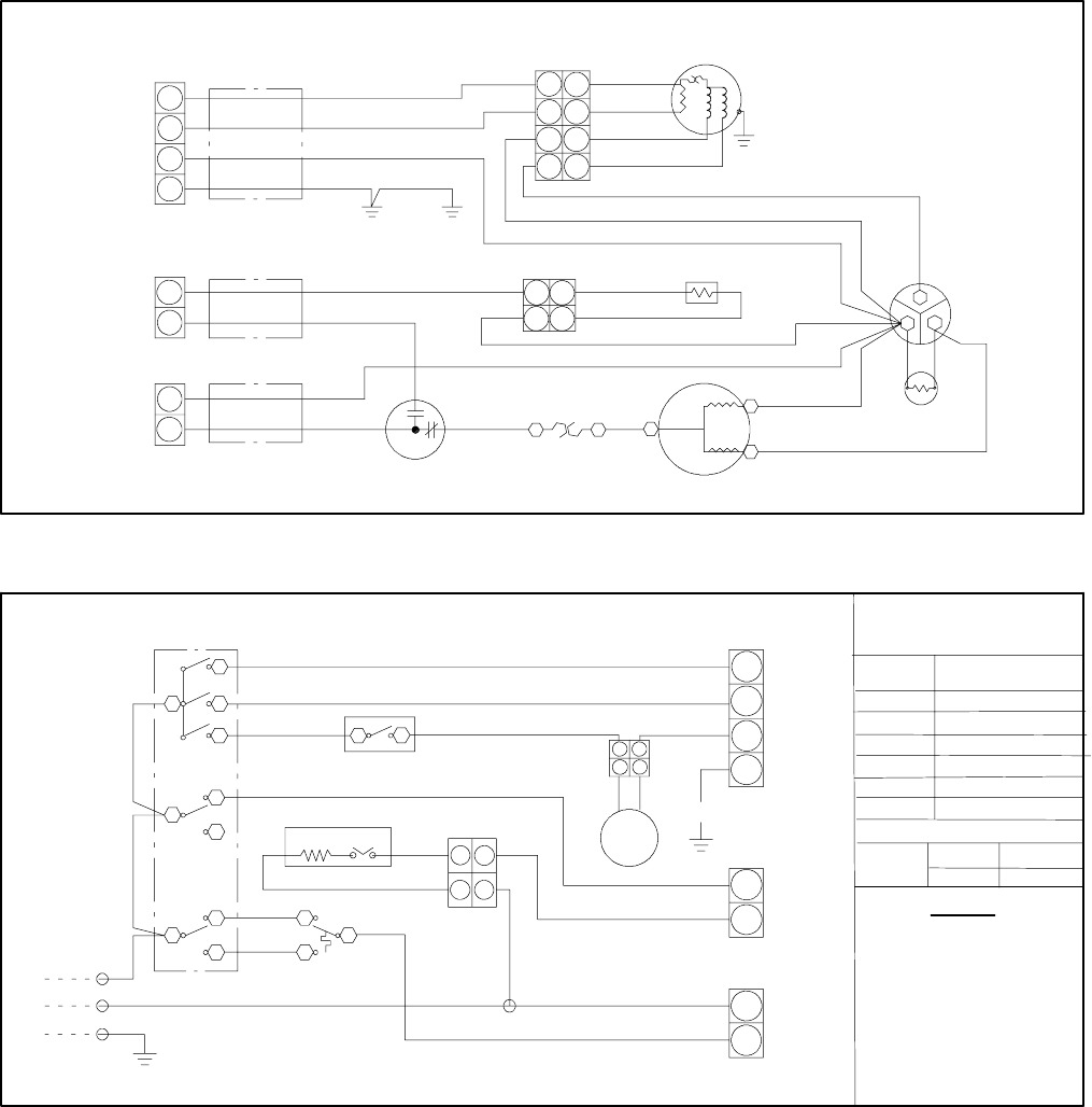
T--298
4-3
CONTROL
BOX EVAP.
RVC
2P
4P
2P
2P
4P
CFH
BLK
BLU
BLK
BLU
WHT
WHT
BRN
BLK
BLK
BLK(BLU)
GRN/YEL GRN/YEL
GRN/YEL
WHT
WHT
WHT
BRN
BRN
1(3)
2
CAPACITOR
YEL
RED
REDOLP
(IF USED)
BLU
BLURED
PTC
COMPRESSOR
R
C
S
FREEZE
SWITCH
FAN MOTOR
1
2
3
4
1
2
1
2
1
2
3
4
1
2
3
4
1
2
1
2
OLP: OVERLOAD PROTECTION
PTC: START THERMISTER
RVC: REVERSING VALVE COIL
PLUG CONNECTS TO CEILING UNIT.
SEE DIAGRAM SUPPLIED WITH
CEILING UNIT FOR ADDITIONAL
WIRING.
Figure 4--6 Heat Pump -- Upper Unit -- Free Blow
PLUG CONNECTS TO UPPER UNIT.
SEE DIAGRAM SUPPLIED WITH
UPPER UNIT FOR ADDITIONAL
WIRING.
HEATER AS
HEATER BT
GRN/YEL
GRN/YEL
4P
2P
2P
2P
2P
{
ORN
WHT
BRN
BLK
WHT
RED
YEL
BLU
BLK
ORN
ORN
WHT
WHT
BLK
ASM
SW
IT
ASW
21
1C
L
H
2
B
L2
33
C
1
HT
A
L1 L
H
YEL
BLK
BLK
BLK
CEC
WHT WHT
SWITCH
POSITION CONTACTS MADE
OFF
LOW FAN
HIGH FAN
LOW COOL
HIGH COOL
HEATING
NONE
L1--L . L1--A
L2--HT.L1--L.L1--A.B--1
L2--C . L1--H . L1--A . B--3
L2--C . L1--L . L1--A . B--3
L1--H . L1--A
ASW O (OFF)
1(ON)
2
2--1
LEGEND
1
2
3
4
1
2
1
2
1
12
2
11
22
ASM: AIR SWEEP MOTOR
ASW: AIR SWEEP SWITCH
SW: SWITCH
IT: INDOOR THERMOSTAT
CEC: CLOSED END CONNECTOR
BT: BIMETAL
115 VAC
SUPPLY
WIRE
Figure 4--7 Heat Pump -- Ceiling Unit -- Free Blow
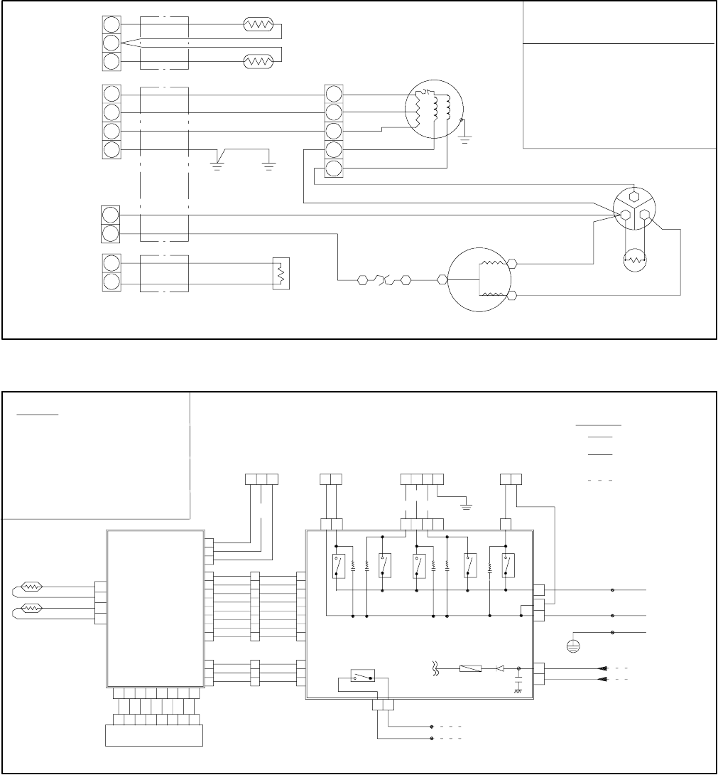
T--298 4-4
LEGEND
RVC
PLUG CONNECTS TO CEILING UNIT.
SEE DIAGRAM SUPPLIED WITH
CEILING UNIT FOR ADDITIONAL
WIRING.
CN
CN
CFH
OLP :OVERLOAD PROTECTOR
PTC :START THERMISTOR
RVC :REVERSING VALVE COIL
CN :HOUSING CONNECTOR
ODA Th :OUTDOOR AIR THERMISTOR
ODC Th :OUTDOOR COIL THERMISTOR
BLK
BLK
BLK(BLU)
CONTROL
BOX EVAP.
BLU
RED
RED
BRN
BLU
WHT
GRN/YEL
GRN/YEL
WHT
WHT
BLK
BRN
BRN
1(3)
2
CAPACITOR
YEL
YEL
RED
OLP
(IF USED)
BLU
BLU
RED
PTC
COMPRESSOR
R
C
S
FAN MOTOR
ODC Th
ODA Th
1
2
3
1
2
3
4
1
2
1
2
1
2
3
5
6
Figure 4--8 Heat Pump -- Upper Unit -- Ducted
ODC ODA RVC MOTOR COMPRESSOR
FUSE D1
250V 3.15A
3
3
33
2
1
7
6
5
4
3
2
111
22
33
44
55
66
7888 7
1
1
1
2
2
2
1
2
3
4
FURNACE SIGNAL
12VDC POWER
(--)
(+)
115VAC POWER
BLK
WHT
BLK
BLK
GRN/YEL
RED
BLU
BLK
RED
BRN
GRN/YEL
WHT
BLK
WHT
BLU BLUBLU
BLK
RED
PLUG CONNECTS TO UPPER UNIT.
SEE DIAGRAM SUPPLIED WITH UPPER UNIT
FOR ADDITIONAL WIRING.
ODA Th :OUTDOOR AIR THERMISTOR
*
*
*
FACTORY WIRING
(12VDC LOW VOLT.)
(115VACHIGHVOLT.)
FIELD WIRING
FIELD WIRING
LEGEND NOTE
CONTROL PCB
POWER PCB ASS’Y
ASS’Y
2
2
4
4
CN9
DISPLAY PCBAS
CN9
1
1
3
3
576
578
8
6
CN1
CN6
CN5
CN6
CN4
CN4
CN1
CN2
CN3CN5
K1
K4K3
K7 K2
K6
11
11
2
22
22
1
33
34
41221
Y
L
N2
N1
12
RA Th
BRN
BLK
IDC Th
IDC Th: INDOOR COIL THERMISTER
RA Th: ROOM AIR THERMISTER
ODC Th: OUTDOOR COIL THERMISTER
RVC: REVERSING VALVE COIL
D1: DIODE
K: RELAY
Figure 4--9 Heat Pump -- Ceiling Unit -- Ducted
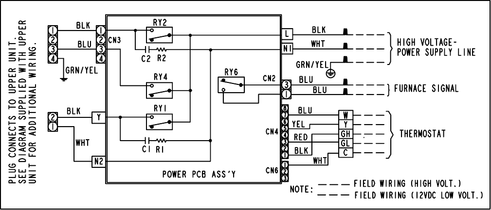
T--298
4-5
Figure 4--10 Ceiling Unit -- Wall Thermostat -- Ducted & Free Blow
4.2 WALL MOUNTED THERMOSTATS
For proper wiring of Wall Mounted Thermostats as an accessory, refer to Figure 3-40 (Wall Thermostat Wiring
Diagram -- Cool Only Model) or Figure 3-41 (Wall Thermostat Wiring Diagram -- Heat/Cool Model).
Index -1 T--298
INDEX
A
Air Handling System , 3-8
Air Sweep Removal, 3-3
Air Sweep Switch , 3-2
C
Capacitor Testing, 3-9
Capacitor Testing and Replacement, 3-9
Ceiling Grill -- Ducted, 3-4
Ceiling Grill -- Free Blow, 3-1
Ceiling Panel -- Free Blow, 3-2
CEILING UNIT -- DUCTED SYSTEMS, 3-4
CEILING UNIT -- FREE BLOW , 3-1
Cleaning, 3-1
Compressor , 3-6, 3-13
Condenser Fan, 3-7
Control Box -- Ducted, 3-4
Control Box -- Upper Unit, 3-6
Controls, 3-1
Cool Only Thermostat, 3-15
D
Design Change, 1-1
E
Evaporator Blower Wheel, 3-8
Exterior Cover, 3-5, 3-10, 3-15
F
Filter Removal -- Free Blow, 3-1
Filter Removal -- Ducted, 3-4
Fuse Removal -- Ducted, 3-5
H
Heat Strip, 3-3
Heat/Cool Thermostat, 3-15
I
Indoor Thermostat , 3-3
INTRODUCTION, 1-1, 4-1
L
LCD DISPLAY, 3-15, 3-16
Leaks, 3-1
M
Main Pcb Board, 3-5
Master Control Switch, 3-2
Motor , 3-7
Mounting, 3-1
P
Painting, 3-1
PCB Display , 3-5
PREVENTATIVE MAINTENANCE, 3-1
R
REFRIGERANT CYCLE, 1-9, 1-10
S
Serial Number, 1-1
SERVICE -- GENERAL, 3-1
SERVICE -- UPPER UNIT -- LOW PROFILE, 3-10
SERVICE AND MAINTENANCE, 3-1
START--UP, 1-9
T
THERMOSTAT INSTALLATION AND START--UP IN-
STRUCTIONS (WALL MOUNTED), 3-15
TROUBLESHOOTING, 2-1, 2-3
U
Upper Scroll Assembly, 3-7, 3-10, 3-11, 3-12, 3-13
W
WIRING SCHEMATICS, 4-1

©2006 Carrier Corporation DPrinted in U. S. A. 0606
Carrier Transport Air Conditioning
50 Grumbacher Road
York PA 17402 USA
Tel: 1--800--673--2431
Fax: 1--717--764--0401
A member of the United Technologies Corporation family. Stock symbol UTX
Carrier Transicold Division,
Carrier Corporation
Transport Air Conditioning Group
P.O. Box 4805
Syracuse, N.Y. 13221 U.S A
www.carrier.transicold.com
