Casi Rusco 94X 940/941 Proximity Readers User Manual Installation guide
Casi Rusco 940/941 Proximity Readers Installation guide
UserManual.wiki
>
Casi Rusco
>
94X User Manual
Installation guide
Navigation menu
Upload a User Manual
Namespaces
Wiki Guide
HTML
PDF
Info
Views
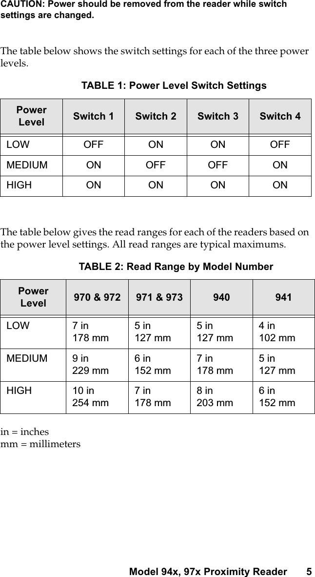
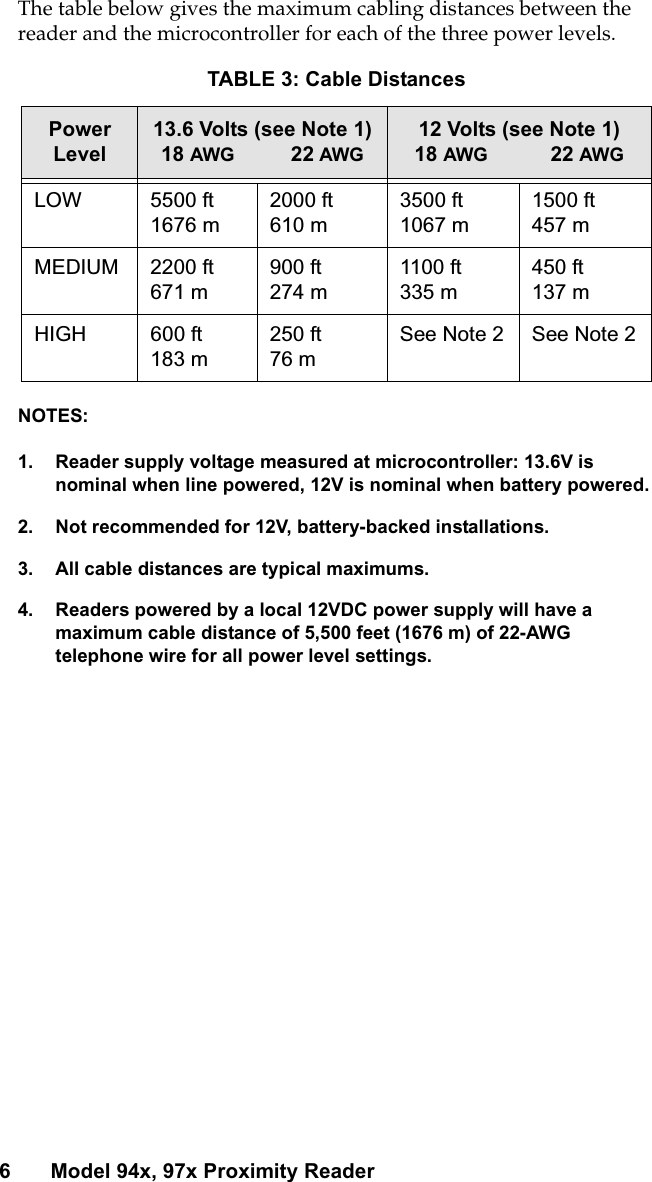
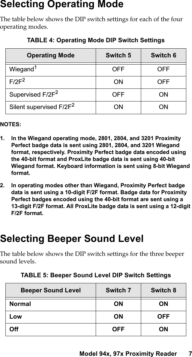
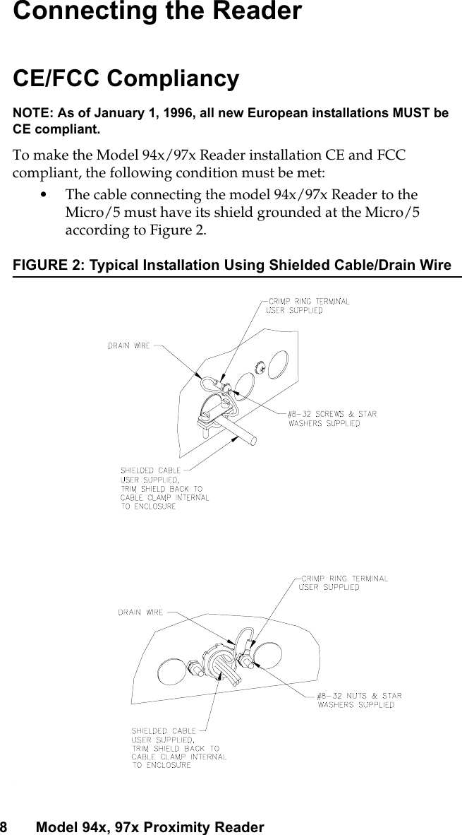
User Manual
Discussion / Help
Navigation