Casi Rusco 94X 940/941 Proximity Readers User Manual Installation guide
Casi Rusco 940/941 Proximity Readers Installation guide
Installation guide

Part Number: 460157001L
January 2002
Model 94x, 97x
Proximity Reader
Installation Guide
CASI
RUSCO
791 Park of Commerce Boulevard
Boca Raton, Florida 33487
(561) 998-6100
CASI-RUSCO...Security Solutions for the 21st Century

This publication may contain examples of data reports used in daily
business operations. Examples include fictitious names of
individuals and companies for illustration only; any similarity to
names and addresses of actual business enterprises and persons is
entirely coincidental.
This document is distributed on an as is basis, without warranty
either expressed or implied. Successful implementation depends
solely upon the customer’s ability to integrate each product into the
total inventory of “in-house” products. While each offering has been
reviewed for its compatibility and maintainability, no assurance of
successful installation can be given.
The customer accepts full maintenance responsibility. (A full scope
of software and hardware maintenance contracts are available to the
customer.)
Copyright 1993, 1994, 1997-2002 CASI-RUSCO
All Rights Reserved
Printed in the USA
ProxLite is a trademark of CASI-RUSCO.
WARNING: This is a Class A product. In a domestic environment, this
product may cause radio interference; in which case, the user may be
required to take adequate measures.

Model 94x, 97x Proximity Reader i
Introduction................................................................................................. 1
Product Features......................................................................................... 2
Switch Settings............................................................................................ 3
Selecting Reader Power Level.....................................................3
Selecting Operating Mode...........................................................7
Selecting Beeper Sound Level .....................................................7
Connecting the Reader .............................................................................. 8
CE/FCC Compliancy ...................................................................8
Pinouts..........................................................................................10
Wiring Diagrams.........................................................................10
Mounting the Reader............................................................................... 17
Testing the Reader.................................................................................... 28
Troubleshooting Guide............................................................................ 29
All Installations ...........................................................................29
Unsupervised Modes Only........................................................31
Supervised Modes Only.............................................................31
Technical Specifications........................................................................... 34
Functional Specifications......................................................................... 36
Contents
ii Model 94x, 97x Proximity Reader
Figures
Figure 1: Model 94x/97x Reader, J1 Connector and DIP Switch
Locations.........................................................................4
Figure 2: Typical Installation Using Shielded Cable/Drain Wire .... 8
Figure 3: Wiring Diagram, Model 94x/97x Supervised
F/2F Mode.....................................................................11
Figure 4: Wiring Diagram, Model 94x/97x Unsupervised
F/2F Mode.....................................................................13
Figure 5: Wiring Diagram, Model 94x/97x Unsupervised Wiegand
Mode ........................................................................... 15
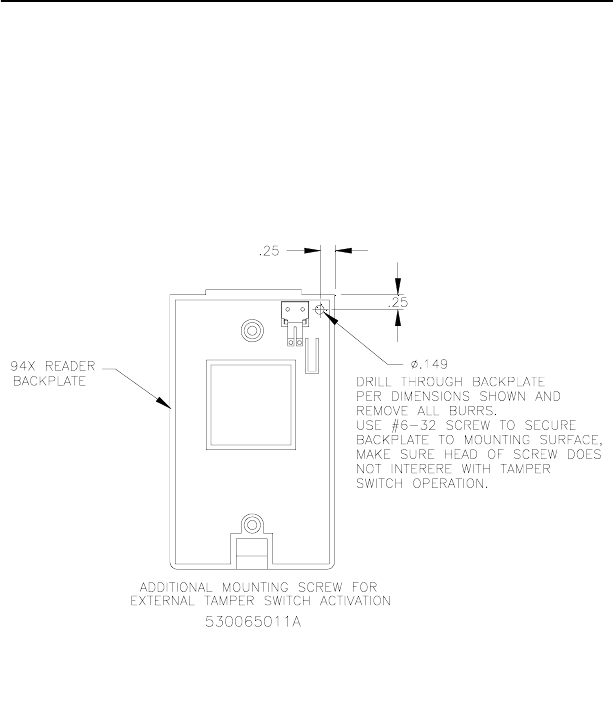
Figure 6: Recommended Additional Mounting Instructions
for External Tamper Switch Activation ..........................19
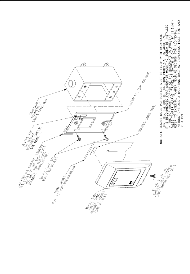
Figure 7: Model 940 Reader - Gang Box Mounting..................... 20
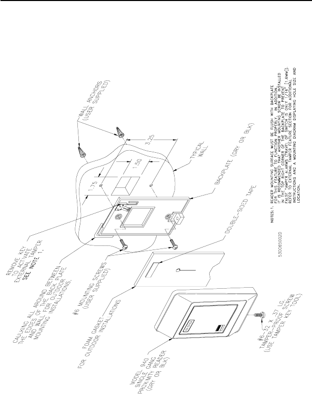
Figure 8: Model 940 Reader - Direct Wall Mounting ................... 21
Figure 9: Model 941 Reader - Gang Box Mounting..................... 22
Figure 10: Model 941 Reader - Direct Wall Mounting ................... 23
Figure 11: Model 970/972 Reader - Gang Box Mounting.............. 24
Figure 12: Model 970/972 Reader - Direct Wall Mounting ............ 25
Figure 13: Model 971/973 Reader - Gang Box Mounting.............. 26
Figure 14: Model 971/973 Reader - Direct Wall Mounting ............ 27
Figure 15: Badge to Reader Presentation..................................... 36
Model 94x, 97x Proximity Reader 1
Introduction
This manual is an installation guide for the CASI-RUSCO Models
940, 941, 970, 971, 972, and 973 Proximity Perfect Readers.
Throughout this guide, the abbreviation 94x represents Reader
Models 940 and 941. The abbreviation 97x represents Reader Models
970, 971, 972, and 973.
The 94x and 97x Readers while similar in functionality offer a variety
of features making them suitable for different applications. The 94x
and 97x Readers are designed to mount on standard U.S. gang boxes.
The 94x Readers are single-gang box size. The 97x Readers are sized
for larger dual gang box installation, offer greater badge read range,
and a keypad option.
Models 940 and 970 give the greatest all-around badge read range for
their respective sizes, making them ideal for most installations.
Models 941 and 971 are tuned for installation on metal mounting
plates. The standard metal mounting plate shields the reader from
the effects of a metal wall, which would otherwise dramatically
reduce the read range. The optional back-to-back metal mounting
plate shields the reader from the effects of a metal wall and makes the
reader unidirectional; ideal for direct back-to-back reader
installations.
Models 972 and 973 are dual gang size readers, identical to the 970
and 971 respectively, except for their built-in twelve-position keypad.
This feature makes these readers ideal for installations requiring
keypad PIN entry in addition to a valid badge read.

2 Model 94x, 97x Proximity Reader
Product Features
The CASI-RUSCO Model 94x/97x Proximity Perfect Reader offers:
• State-of-the-art architecture.
• The ability to read all Proximity Perfect, ProxLiteTM,andEntrée
badges and key tags.
• Proximity Perfect badge read ranges up to 10 inches (254 mm) for
970 Readers and up to 8 inches (203 mm) for 940 Readers (See
Table 2 “Read Range by Model Number,” on page 5).
• Field changeable DIP switches allow all 94x and 97x Readers to
operate in one of four distinct operating modes: Wiegand, F/2F,
Supervised, and Silent Supervised. Silent Supervised mode is
ideal for installations where no audible or visual indication of
communication loss with the microcontroller is desired at the
reader.
In the unsupervised modes, the reader communicates with the
microcontroller over a unidirectional Wiegand or F/2F data link
that carries Proximity Perfect badge data only.
In the supervised modes, the reader communicates with the
microcontroller over a bidirectional F/2F data link, that carries
the following:
Proximity Perfect badge data
Supervision messages
Exit request and door switch status
Microcontroller acknowledgments and commands
• Intelligent bidirectional communication between the reader and
microcontroller, which can be accomplished up to 5,500 feet.
• Weather-resistant housing for outdoor use.
• Standard 12V operation.
• A clear, logical user interface with three LEDs and a beeper.
• Rugged molded ABS construction with integral backplate.
• Built-in tamper alarm also detects removal from wall.
• External tamper alarm option.
• Tactile keypad (Models 972 and 973 only) for Personal
Identification Number (PIN) input.
• Switch selectable beeper enable/disable and volume control.
• UL verified for indoor use only.
Model 94x, 97x Proximity Reader 3
Switch Settings
Two banks of four DIP switches located on the back of the reader are
used to select the reader power level, operating mode, and beeper
sound level.
CAUTION: Power should be removed from the reader while switch
settings are changed.
Selecting Reader Power Level
The reader’s power requirement is selected using four DIP switches.
The optimum power level will vary with each installation. Higher
power levels give improved read range for Proximity Perfect badges,
while lower power levels allow greater cabling distance between the
reader and the microcontroller. A detailed explanation is provided
below. The figure on the next page shows the location of the DIP
switches. The tables that follow the figure give the switch settings
along with the read ranges and cable distances.
Explanation of Read Range/Cable Distance/Power Level:
Maximum badge read range is determined by the distance at which
the field transmitted by the reader is just strong enough to wake up the
badge. Therefore, the higher the reader’s transmission power, the
greater the badge read range will be. The trade-off for increased read
range is a decrease in the maximum cabling distance between the
reader and the microcontroller. The trade-off between read range and
cabling distance is common to all proximity badge readers. The
power selection switches on the 94x/97x readers allow the optimum
power setting to be selected to suit individual installations.
4 Model 94x, 97x Proximity Reader
For example: On the high power setting, giving the greatest badge
read range, the reader typically requires 200mA of supply current
from the microcontroller. If there is 1,000 feet of 22-AWG cable
between the reader and the microcontroller, the total reader power
and power return path is 2,000 feet. Since 22-AWG cable has a typical
resistance of 16 ohms per 1,000 feet, the total resistance in the reader’s
power and power return wire is 32 ohms. By Ohms Law (V=IR), it
follows that the total voltage dropped in the reader power and power
return wires will be 6.4V (6.4V = 200mA x 32 Ohms). Therefore, the
reader supply voltage will drop from 12V at the microcontroller to
5.6V (12V - 6.4V) at the reader. Such a supply voltage is too low for
the reader to function reliably.
If the low power setting is selected, the badge read range is reduced.
However, the reader now typically requires only 75mA of supply
current; therefore, the voltage drop in the power and power return
wires is much less. In this case, the reader supply voltage will only be
reduced to 9.6V; high enough for reliable operation.
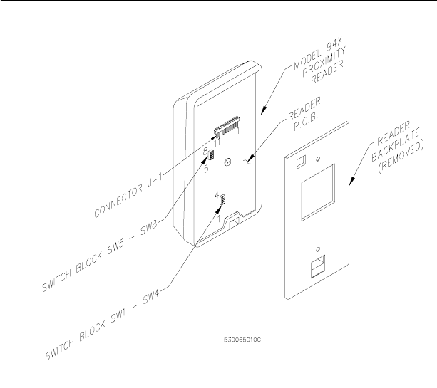
FIGURE 1: Model 94x/97x Reader, J1 Connector and
DIP Switch Locations

Model 94x, 97x Proximity Reader 5
CAUTION: Power should be removed from the reader while switch
settings are changed.
The table below shows the switch settings for each of the three power
levels.
The table below gives the read ranges for each of the readers based on
thepowerlevelsettings.Allreadrangesaretypicalmaximums.
in = inches
mm = millimeters
TABLE 1: Power Level Switch Settings
Power
Level Switch 1 Switch 2 Switch 3 Switch 4
LOW OFF ON ON OFF
MEDIUM ON OFF OFF ON
HIGH ON ON ON ON
TABLE 2: Read Range by Model Number
Power
Level 970 & 972 971 & 973 940 941
LOW 7 in
178 mm
5in
127 mm
5in
127 mm
4in
102 mm
MEDIUM 9 in
229 mm
6in
152 mm
7in
178 mm
5in
127 mm
HIGH 10 in
254 mm
7in
178 mm
8in
203 mm
6in
152 mm

6 Model 94x, 97x Proximity Reader
The table below gives the maximum cabling distances between the
reader and the microcontroller for each of the three power levels.
NOTES:
1. Reader supply voltage measured at microcontroller: 13.6V is
nominal when line powered, 12V is nominal when battery powered.
2. Not recommended for 12V, battery-backed installations.
3. All cable distances are typical maximums.
4. Readers powered by a local 12VDC power supply will have a
maximum cable distance of 5,500 feet (1676 m) of 22-AWG
telephone wire for all power level settings.
TABLE 3: Cable Distances
Power
Level
13.6 Volts (see Note 1)
18 AWG 22 AWG
12Volts(seeNote1)
18 AWG 22 AWG
LOW 5500 ft
1676 m
2000 ft
610 m
3500 ft
1067 m
1500 ft
457 m
MEDIUM 2200 ft
671 m
900 ft
274 m
1100 ft
335 m
450 ft
137 m
HIGH 600 ft
183 m
250 ft
76 m
See Note 2 See Note 2

Model 94x, 97x Proximity Reader 7
Selecting Operating Mode
The table below shows the DIP switch settings for each of the four
operating modes.
NOTES:
1. In the Wiegand operating mode, 2801, 2804, and 3201 Proximity
Perfect badge data is sent using 2801, 2804, and 3201 Wiegand
format, respectively. Proximity Perfect badge data encoded using
the 40-bit format and ProxLite badge data is sent using 40-bit
Wiegand format. Keyboard information is sent using 8-bit Wiegand
format.
2. In operating modes other than Wiegand, Proximity Perfect badge
data is sent using a 10-digit F/2F format. Badge data for Proximity
Perfect badges encoded using the 40-bit format are sent using a
13-digit F/2F format. All ProxLite badge data is sent using a 12-digit
F/2F format.
Selecting Beeper Sound Level
The table below shows the DIP switch settings for the three beeper
sound levels.
TABLE 4: Operating Mode DIP Switch Settings
Operating Mode Switch 5 Switch 6
Wiegand1OFF OFF
F/2F2ON OFF
Supervised F/2F2OFF ON
Silent supervised F/2F2ON ON
TABLE 5: Beeper Sound Level DIP Switch Settings
Beeper Sound Level Switch 7 Switch 8
Normal ON ON
Low ON OFF
Off OFF ON
8 Model 94x, 97x Proximity Reader
Connecting the Reader
CE/FCC Compliancy
NOTE: As of January 1, 1996, all new European installations MUST be
CE compliant.
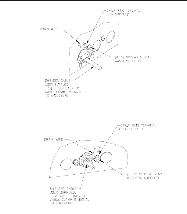
To make the Model 94x/97x Reader installation CE and FCC
compliant, the following condition must be met:
• The cable connecting the model 94x/97x Reader to the
Micro/5 must have its shield grounded at the Micro/5
according to Figure 2.
FIGURE 2: Typical Installation Using Shielded Cable/Drain Wire
Outside Micro/5 Enclosure

Model 94x, 97x Proximity Reader 9
Manufacturers Declaration
of Conformity
(Subject to the conditions on page 8)
Manufacturer’s
Name: CASI-RUSCO
Manufacturer’s
Address:
791 Park of Commerce Boulevard
Boca Raton, FL USA 33487
EU Representative: Interlogix Europe & Africa
Excelsiorlaan 28
B- 1930 Zaventum
Belgium
Product
Identification:
Product: Proximity Reader
Model Number: Model 94x/97x
Brand: CASI-RUSCO
Means of Conformity: • Hereby, CASI-RUSCO, declares that this
equipment is in compliance with the essential
requirements and other relevant provisions of
Directive 1999/5/EC.
• Hierbij verklaart CASI-RUSCO dat het apparoat
in overeenstemming is met de essentiële eisen
en de andere relevante bepalingen van richtlijn
1999/5/EG.
• Par la présente CASI-RUSCO déclare que
l'appareil est conforme aux exigences
essentielles et aux autres dispositions
pertinentes de la directive 1999/5/CE.
• Hiermit erklärt CASI-RUSCO, dass sich diese
auspüstung in Übereinstimmung mit den
grundlegenden Anforderungen und den
anderen relevanten Vorschriften der Richtlinie
1999/5/EG befindet". (BMWi)
Notices: Approved for use in the following countries:
A
B
DK
FIN
IS
IRL
GR
D
I
NL
F
CZ
H
LU
N
PL
P
E
S
CH
GB

10 Model 94x, 97x Proximity Reader
Pinouts
The table below shows the pinouts for connecting the reader to the
microcontroller. Connector J1, pin 1 is to the right as you view the
connector from behind the reader. See Figure 1, “Model 94x/97x
Reader, J1 Connector and DIP Switch Locations,” on page 4.
Wiring Diagrams
See the wiring diagrams that follow for details on connecting the
reader to the microcontroller based on the mode of the reader.
TABLE 6: Pinouts
Connector
J1 Pin # Signal Pigtail Wire
Color
1+12VDC Red
2Ground Black
3 Red LED External Drive Blue
4 Green LED External Drive Brown
5 Yellow LED External Drive Orange
6 Reader Data 0 Green
7 Reader Data 1 White
8 Beeper External Drive Violet
9 Keying Pin
10 Door DI (Door Contact Switch) Yellow
11 Exit DI (Exit Request Button) Gray
Model 94x, 97x Proximity Reader 11
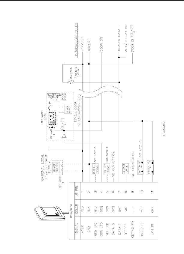
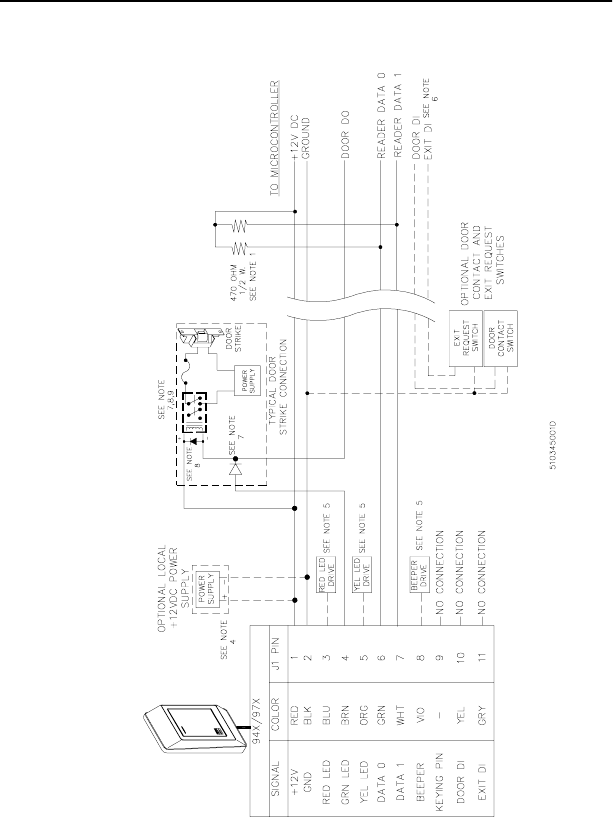
FIGURE 3: Wiring Diagram, Model 94x/97x
Supervised F/2F Mode
12 Model 94x, 97x Proximity Reader
NOTES (Unless otherwise specified):
1. For Micro/2/4/5 only: a 470 ohm, 1/2W, pull-up resistor is required between +12VDC and READER DATA 1. The pull-up
resistor should be installed at the microcontroller’s terminal block. Resistors are supplied with the reader.
2. Shielded cable is recommended in electrically noisy environments.
3. If using shielded cable, connect all shields together at the micro end. Connect to ground stud in the lower left corner
of Micro/2/4/5 cabinets using 14-AWG wire. No shield connections at the reader.
4. If using a local power supply, do not connect +12V line from the microcontroller to the reader. However, the negative
side of the power supply must be connected to the micro (pin 2 on the reader port). Keep the wiring from power
supply to reader less than 50 feet.
5. Switching the external indicator drives to GND activates the indicator. High impedance or +12V deactivates
indicators. These drives may also be connected to user supplied, external indicating circuitry.
6. Refer to the appropriate system manual to determine whether this connection is required for door switch operation.
7. Blocking diodes may be 1N4148 or similar, supplied by the installer and located in a secured area.
8. Protection diodes may be 1N4002, 1N4003, or 1N4004 (installer supplied) for the door strike assembly.
9. Fuse, power supply, door strike, and relay are provided by the installer.
10. If the door contact switch is not used, link reader pin 10 to pin 2.
Model 94x, 97x Proximity Reader 13
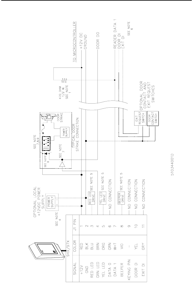
FIGURE 4: Wiring Diagram, Model 94x/97x
Unsupervised F/2F Mode
14 Model 94x, 97x Proximity Reader
NOTES (Unless otherwise specified):
1. For Micro/2/4/5 only: a 470 ohm, 1/2W, pull-up resistor is required between +12VDC and READER DATA 1. The pull-up
resistor should be installed at the microcontroller’s terminal block. Resistors are supplied with the reader.
2. Shielded cable is recommended in electrically noisy environments.
3. If using shielded cable, connect all shields together at the micro end. Connect to ground stud in the lower left corner
of Micro/2/4/5 cabinets using 14-AWG wire. No shield connections at the reader.
4. If using a local power supply, do not connect +12V line from the microcontroller to the reader. However, the negative
side of the power supply must be connected to the micro (pin 2 on the reader port). Keep the wiring from power
supply to reader less than 50 feet.
5. Switching the external indicator drives to GND activates the indicator. High impedance or +12V deactivates
indicators. These drives may also be connected to user supplied, external indicator driving circuitry.
6. Refer to the appropriate system manual for specific wiring details.
7. Blocking diodes may be 1N4148 or similar, supplied by the installer, and located in a secured area.
8. Protection diodes may be 1N4002, 1N4003, or 1N4004 (installer supplied) for the door strike assembly.
9. Fuse, power supply, door strike, and relay are provided by the installer.
Model 94x, 97x Proximity Reader 15
FIGURE 5: Wiring Diagram, Model 94x/97x
Unsupervised Wiegand Mode
16 Model 94x, 97x Proximity Reader
NOTES (Unless otherwise specified):
1. For Micro/2/4/5 only: two 470 ohm, 1/2W, pull-up resistors are required; one between +12VDC and READER DATA 1,
the other between +12VDC and READER DATA 0. The pull-up resistors should be installed at the microcontroller’s
terminal block. Resistors are supplied with the reader.
2. Shielded cable is required. Belden 8725 wire is recommended. Do not pair DATA 1 and DATA 0.
3. If using shielded cable, connect all shields together at the micro end. Connect to ground stud in the lower left corner
of Micro/2/4/5 cabinets using 14-AWG wire. No shield connections at the reader.
4. If using a local power supply, do not connect +12V line from the microcontroller to the reader. However, the negative
side of the power supply must be connected to the micro (pin 2 on the reader port). Keep the wiring from power
supply to reader less than 50 feet.
5. Switching the external indicator drives to GND activates the indicator. High impedance or +12V deactivates
indicators. These drives may also be connected to user supplied, external indicator driving circuitry.
6. Refer to the appropriate system manual for specific wiring details.
7. Blocking diodes may be 1N4148 or similar, supplied by the installer, and located in a secured area.
8. Protection diodes may be 1N4002, 1N4003, or 1N4004 (installer supplied) for the door strike assembly.
9. Fuse, power supply, door strike, and relay are provided by the installer.
Model 94x, 97x Proximity Reader 17
Mounting the Reader
The reader comes with a backplate suitable for mounting directly
onto standard U.S. electrical gang boxes (Model 94x onto single-gang
box and Model 97x onto dual-gang box). The reader may also be
mounted directly onto a hollow wall.
Back-to-Back Readers: Models 941, 971 and 973 Readers are
suitable for back-to-back installation (to provide in/out access
control). Using the standard metal mounting plates, the two readers
should be mounted with their centers offset by at least 10 inches to
provide interference-free operation. Using the optional back-to-back
metal mounting plates allows the two readers to be mounted directly
opposite each other on a 4-inch thick wall.
Important:
• Readers should not be mounted within three feet of a computer
terminal. Some terminals radiate electrical noise that may reduce
the effective maximum read range.
• Never mount Models 940, 970 or 972 on or near metal. Metal
effects the tuning of the reader and may severely degrade its
performance, decreasing read range and increasing current draw.
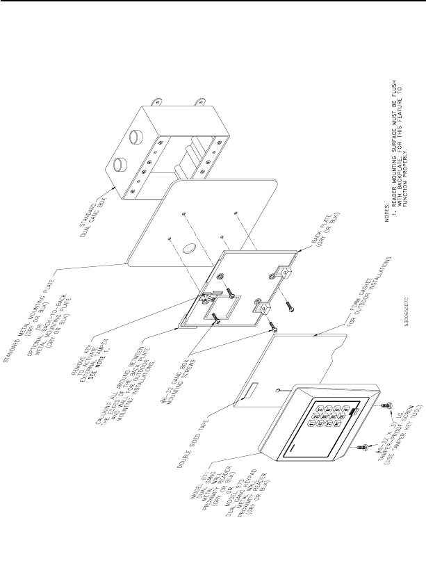
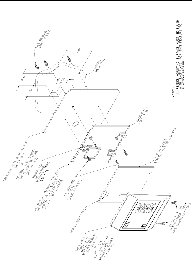
• Models 941, 971 and 973 are factory tuned to work with a metal
backandmustbemountedwiththemetalmountingplateto
operate correctly.
• A gasket is supplied with the reader to form a weather-resistant
seal between the mounting surface and the inside of the reader
for outdoor installations. The gasket should be located on the
inside surface of the reader’s plastic backplate. For outdoor
installations, where the reader is mounted in direct exposure to
weather, a bead of silicone caulking should be applied between
the reader and the wall to prevent water from entering the back
of the reader.
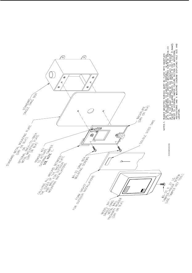
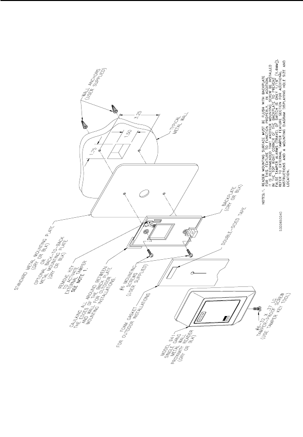
External Tamper Feature: The Model 94x/97x Readers are also
equipped with an external tamper feature. This feature can be
activated by removing the key on the backplate prior to mounting.
Model 94x Only: Apply the mounting method as shown in Figure 6,
to mounting instructions in Figure 7, Figure 8, Figure 9, and
Figure 10, if you are using the external tamper feature.
NOTE: In order for this feature to work properly, the reader mounting
surface must be flush with the backplate.
18 Model 94x, 97x Proximity Reader
The figures listed below begin on the next page. Refer to the
appropriatefigureforthetypeofreaderyouaremounting.
Figure 6, “Recommended Additional Mounting Instructions for
External Tamper Switch Activation,” on page 19.
Figure 7, “Model 940 Reader - Gang Box Mounting,” on page 20.
Figure 8, “Model 940 Reader - Direct Wall Mounting,” on page 21.
Figure 9, “Model 941 Reader - Gang Box Mounting,” on page 22.
Figure 10, “Model 941 Reader - Direct Wall Mounting,” on page 23.
Figure 11, “Model 970/972 Reader - Gang Box Mounting,” on
page 24.
Figure 12, “Model 970/972 Reader - Direct Wall Mounting,” on
page 25.
Figure 13, “Model 971/973 Reader - Gang Box Mounting,” on
page 26.
Figure 14, “Model 971/973 Reader - Direct Wall Mounting,” on
page 27.
20 Model 94x, 97x Proximity Reader
FIGURE 7: Model 940 Reader - Gang Box Mounting
Model 94x, 97x Proximity Reader 21
FIGURE 8: Model 940 Reader - Direct Wall Mounting
22 Model 94x, 97x Proximity Reader
FIGURE 9: Model 941 Reader - Gang Box Mounting
Model 94x, 97x Proximity Reader 23
FIGURE 10: Model 941 Reader - Direct Wall Mounting
24 Model 94x, 97x Proximity Reader
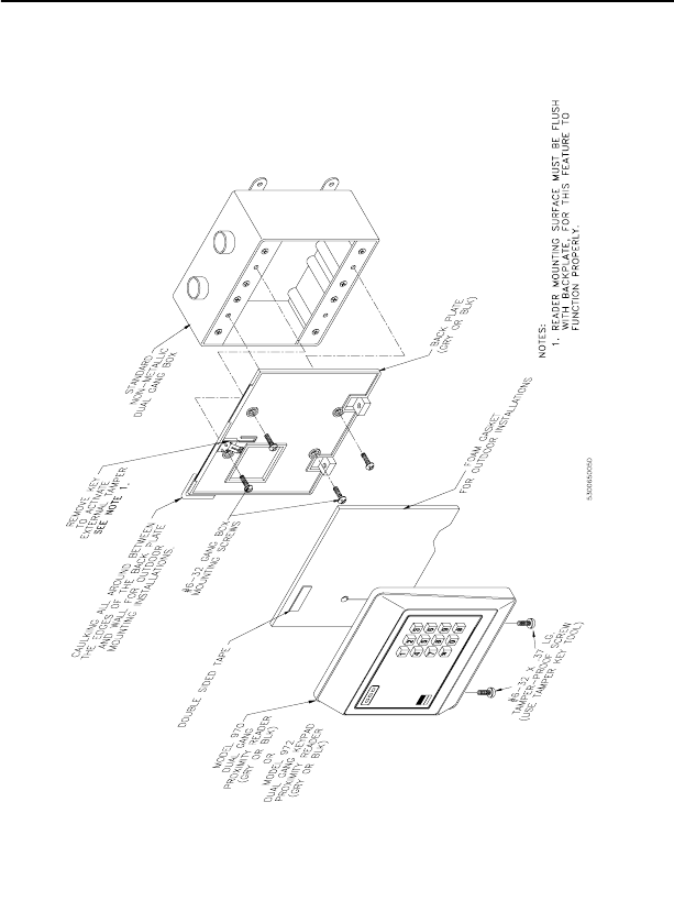
FIGURE 11: Model 970/972 Reader - Gang Box Mounting
Model 94x, 97x Proximity Reader 25
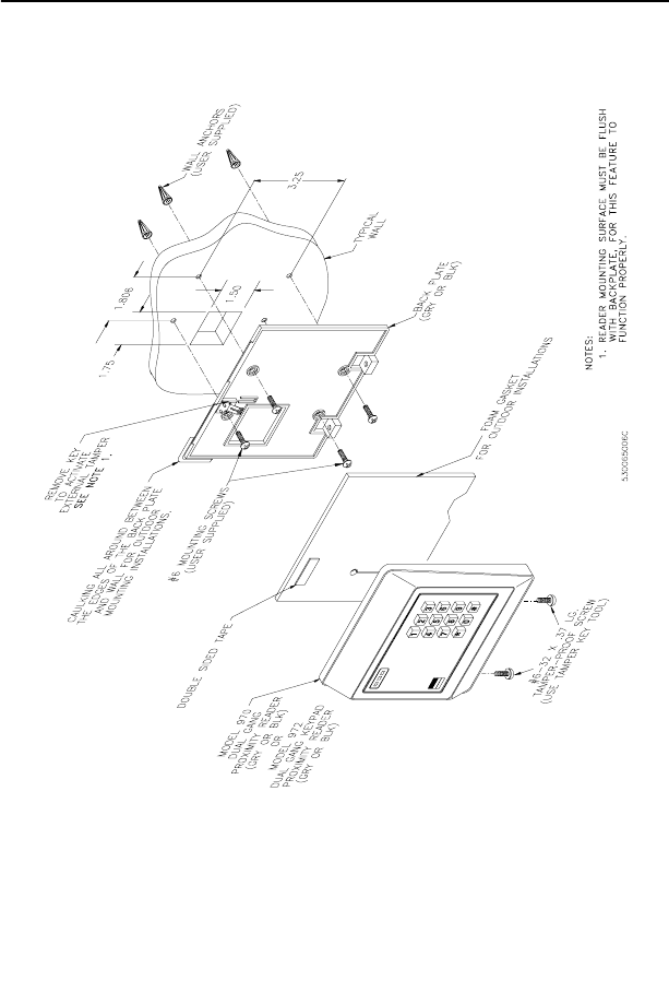
FIGURE 12: Model 970/972 Reader - Direct Wall Mounting
26 Model 94x, 97x Proximity Reader
FIGURE 13: Model 971/973 Reader - Gang Box Mounting
Model 94x, 97x Proximity Reader 27
FIGURE 14: Model 971/973 Reader - Direct Wall Mounting
28 Model 94x, 97x Proximity Reader
Testing the Reader
Follow the steps below to verify that the reader is working correctly.
1. Check all cabling and electrical connections from the reader to
the microcontroller. Refer to the wiring diagrams on page 11,
page 13, and page 15.
2. Verify that the microcontroller is properly configured. Refer to
the appropriate CASI-RUSCO microcontroller manual.
3. Verify that the reader switches are properly set for the power
setting, cabling type, distance, and desired mode of operation.
See “Switch Settings” on page 3.
4. Apply power to the reader and verify that the yellow LED is on.
You may want to use a multimeter to test the voltage at the
reader’s pigtail connector J1, using ground (pin 2) as a reference.
The power pin (pin 1), data lines (pins 6 and 7) and door DO
(pin 4) should all read approximately 12V.
5. Check that the proper version of firmware is installed in the
microcontroller. Refer to the appropriate microcontroller manual.
6. Close the tamper switch by joining the reader and backplate.
NOTE: If external tamper is activated, make sure the reader
backplate mounting surface is flush with backplate. When all wires
are connected to the reader, ensure that the supervision function
is operating properly (if a supervised mode is selected), by
verifying that the reader is not sounding a short triple beep every
30 seconds, and the red LED is not flashing slowly (every 2
seconds). If such an alarm is present, refer to the troubleshooting
guide at the end of this manual. NOTE: In silent supervised mode,
no indication of loss of supervision is provided, except badges will
not be read.
7. Select a known good Proximity Perfect or ProxLite test badge. Be
sure the badge is properly entered in the host system, and the
micro badge data format matches the reader. If the reader is used
with a keypad (Models 972 and 973 only), assign a proper PIN.
8. Check that the door is secure. Present the badge to the reader.
Observe that the reader beeps briefly and the yellow LED
blinks off.
Model 94x, 97x Proximity Reader 29
9. If the reader is used with a keypad (Models 972 and 973 only),
enter a PIN. Refer to the host manual for instructions on entering
the PIN. Observe that the green LED turns on indicating a valid
access has been granted by the host.
10. Open the door. This verifies that the door strike operates
correctly.
Troubleshooting Guide
If the operation of a component is in doubt, substitute a known good
component and retry the system. Always verify wiring against
wiring diagrams before powering up the system.
The troubleshooting guide is divided into three sections. The first
section is applicable to all installations, the second section provides
additional diagnosis for unsupervised readers, and the last section
provides additional diagnosis for supervised readers.
All Installations
All LEDs are on and the beeper is on (if enabled): Usually, an
indication that the reader’s voltage is too low. This may be caused if
the wrong reader voltage is selected at the microcontroller or the
cabel is too long between the reader and the microcontroller.
1. Measure the reader supply voltage at the microcontroller. It
should read between 12 and 15VDC. If the voltage is correct,
continue to step 2 below. If the voltage is incorrect, refer to the
appropriate microcontroller manual and correct the voltage.
2. Set the reader to low power mode if the cable distance is too long
(See Table 1 “Power Level Switch Settings,” on page 5). This may
correct the problem.
3. If the problem is still present, while in low power mode, measure
the voltage between J1 pin 1 (power) and J1 pin 2 (ground). This
voltage should be greater than 8VDC and less than or equal to the
reader supply voltage. If the voltage is too low, correct the
wiring. If the voltage is correct, replace the reader.
None of the LEDs are on: Check that the beeper is enabled (See
Table 5 “Beeper Sound Level DIP Switch Settings,” on page 7), then
present a known good Proximity Perfect or ProxLite test badge to the
reader while listening for the beeper.
30 Model 94x, 97x Proximity Reader
If the beeper sounds, the reader is faulty and should be replaced. If
the beeper does not sound, check the power connections to the reader
and check the reader supply voltage at connector J1 pin 1.
The green LED is always on: The green LED indicates that the door
strike is open. It is controlled by the input on connector J1 pin 4.
1. Disconnect the wire on J1 pin 4. If the green LED stays on, the
reader is faulty and should be replaced. If the green LED goes off
then the problem is most likely not in the reader.
2. Reconnect the wire on J1 pin 4 and measure the voltage at J1
pin4.LowvoltageturnsonthegreenLED.Ifthevoltageislow,
check to see if the host system is turning on the door strike.
The beeper doesn’t sound and the yellow LED doesn’t blink when
a badge is presented to the reader OR the badge read range is very
poor: When the beeper sounds and the yellow LED blinks off, it
indicates that a badge has been read and its data sent to the
microcontroller.
NOTE: The beeper will not sound if it has been disabled. (See Table 5
“Beeper Sound Level DIP Switch Settings,” on page 7.)
1. Models 941, 971 and 973: Check that the metal backplate is
installed correctly. See the appropriate installation drawing in
this manual for details.
Allothermodels:Besuretheyarenotmountedonorneara
metalwallorlargemetalobject.
2. Check that the reader is not mounted within 3 feet (1 meter) of a
computer terminal or within 10 inches (250 mm) of another
Proximity Perfect reader. The only exception to this 10-inch
(250 mm) limit is for 941, 971, and 973 Readers installed on the
optional, back-to-back, metal mounting plates.
3. Present a Proximity Perfect test badge (known to be working) to
the reader. If the beeper and yellow LED still fail to indicate a
valid badge read and send, replace the reader with a reader that
you know is working correctly. If this corrects the problem, the
original reader is faulty and should be replaced. If this does not
correct the problem, the badge is probably defective.
ThedoordoesnotopenandthegreenLEDdoesnotturnonwhena
badge is presented:
1. Verify that the badge and reader are properly entered into the
system.
Model 94x, 97x Proximity Reader 31
2. Verify that the door strike and the green LED are wired correctly.
Since the green LED and the door strike are separate indicators,
this problem is not an indication of a defective reader.
The green LED does not turn on, but the door strike unlocks the door
when a valid badge is presented:
1. Verify that the door DO is wired correctly. Refer to the
appropriate wiring diagram.
2. DisconnectthewirefromJ1pin4(greenLED)andconnectJ1
pin 4 to J1 pin 2 (ground). If the green LED is now on, the reader
is good and the connection to the reader is defective. If the green
LED does not turn on, replace the reader.
Green LED turns on but the door does not open: Verify correct door
strike wiring and operation. The reader is functioning properly.
The beeper is always on and/or the yellow LED is off: The yellow
LED blinks off and the beeper sounds while a key is pressed (Models
972 and 973 only), as long as the reader DIP switches are not set to
disable the beeper.
Unsupervised Modes Only
The reader sounds a short triple beep every 30 seconds and the red
LED flashes quickly (every 400 ms): Indicates a tamper violation.
Verify that the reader housing is properly secured to the backplate. If
an external tamper is used, review the appropriate recommended
mounting instructions. If the reader is secure and mounted properly,
then the reader is faulty and should be replaced.
Supervised Modes Only
Reader sounds a short triple beep every 30 seconds and the red LED
flashes slowly (every 2 seconds): The reader has lost communication
with the microcontroller.
1. Check the reader to microcontroller wiring. Refer to the
appropriate installation drawing. Verify that the AUX DO is
jumpered to the READER DATA 1 on the microcontroller.
2. Verify that the correct pull-up resistor is installed on the
microcontroller. See Figure 3, “Wiring Diagram, Model 94x/97x
Supervised F/2F Mode,” on page 11.
32 Model 94x, 97x Proximity Reader
3. Verify that the microcontroller has the correct firmware for a
supervised reader. Refer to the manual that came with your
microcontroller for instructions.
4. Try the reader on a different reader input of the microcontroller.
If this corrects the problem, then the microcontroller is probably
causing the problem.
5. Replace the reader with one you know is working correctly. If
this corrects the problem, then the reader is probably faulty and
should be replaced.
6. If none of the above steps have identified the problem, there may
be a significant noise source present in the installation that is
interfering with the reader-to-microcontroller communications. If
thisisthecase,useshieldedwireforreader-to-microcontroller
connections.
The beeper sounds and the yellow LED blinks off more than once
when a valid badge is presented: The beeper sounds and the yellow
LED blinks off every time badge data is sent to the microcontroller.
When a badge is presented to the reader, data is transmitted from the
badge to the reader. The reader interprets and checks the data
received to make sure it has not been corrupted. The reader then
sends the data to the microcontroller and waits approximately 1/3 of
a second for the microcontroller to acknowledge receipt. If no
acknowledge is received during this time, the reader resends the data
causing the beeper to sound again and the LED to blink off. After the
third unacknowledged attempt, the reader stops trying and indicates
a communications error. This feature is useful in troubleshooting
marginal installations where a high level of electrical noise may cause
the reader to make multiple attempts at communications.
1. If multiple beeps occur regularly, refer to the installation
drawings to verify that the correct pull-up resistor has been
added to the microcontroller.
2. Replace the reader with one you know is working correctly. If
this solves the problem, the original reader is probably faulty and
should be replaced. If the problem persists, use shielded cable
between the microcontroller and the reader.
The reader sounds a short triple beep every 30 seconds and the red
LED flashes quickly (every 400 ms): Indicates a tamper violation.
Verify that the reader housing is properly secured to the backplate. If
an external tamper is used, review the appropriate recommended
mounting instructions. If the reader is secure and mounted properly,
Model 94x, 97x Proximity Reader 33
then the reader is faulty and should be replaced.
The beeper and/or red LED are always on: The microcontroller may
command the reader to turn on the red LED and the beeper as long as
the reader DIP switches are not set to disable the beeper. If the door
statusswitchinputatJ1pin10isnottiedtoground,thereader
informsthesystemthatthedoorisopen.Thesystemmaythen
activate the alarm at the reader. If this is not the problem, then the
system software probably told the reader to activate its alarm. Refer
totheappropriatesystemmanualforconditionsthatcausethe
software to activate the alarm. If it appears that no such system
command is active, replace the reader with one you know works
correctly.Ifthissolvestheproblem,theoriginalreaderisfaultyand
should be replaced.
The green LED flashes quickly (every 400 ms): This indicates that
the microcontroller has requested a PIN entry on a Model 972 or 973
Reader with a keypad. For all other models, check the reader
configuration on your system to be sure a keypad reader was not
selected.
34 Model 94x, 97x Proximity Reader
Technical Specifications
Operating Temperature Range:-35°Cto+66°C (-31°Fto151° F)
Humidity Range: 0% to 95%
Index of Protection: IP55
Physical Dimensions:
Models 94x - 4.75 in (H) x 2.90 in (W) x 0.90 in (D)
121mm(H)x74mm(W)x23mm(D)
Models 97x - 4.75 in (H) x 5.500 in (W) x 0.90 in (D)
121 mm (H) x 140 mm (W) x 23 mm (D)
Parts List:
• Model 940 Reader (single-gang) gray
• Model 940 Reader (single-gang) black
• Model 941 Reader (single-gang metal mount) gray
• Model 941 Reader (single-gang metal-mount) black
• Model 970 Reader (dual-gang) gray
• Model 970 Reader (dual-gang) black
• Model 971 Reader (dual-gang metal-mount) gray
• Model 971 Reader (dual-gang metal-mount) black
• Model 972 Reader (dual-gang with keypad) gray
• Model 972 Reader (dual-gang with keypad) black
• Model 973 Reader (dual-gang metal mount w/keypad) gray
• Model 973 Reader (dual-gang metal mount w/keypad) black
• Optional Tamper Key Tool
• 94x Plastic Backplate (gray)
• 94x Plastic Backplate (black)
• 97x Plastic Backplate (gray)
• 97x Plastic Backplate (black)
• Standard 941 Metal Mounting Plate (gray)
• Standard 941 Metal Mounting Plate (black)
• Standard 971/973 Metal Mounting Plate (gray)
• Standard 971/973 Metal Mounting Plate (black)
Model 94x, 97x Proximity Reader 35
• OptionalBack-to-Back941MetalMountingPlate(gray)
• Optional Back-to-Back 971/973 Metal Mounting Plate (black)
• 94x Weather-resistant Gasket
• 97x Weather-resistant Gasket
•ReaderCable
Refer to CASI-RUSCO Product Catalog for part numbers and
ordering information.
Maximum Reader Range: Determined by the reader’s power level
setting. See Table 2 “Read Range by Model Number,” on page 5.
Maximum Cabling Distance: The maximum cable distance
between the reader and the microcontroller is influenced by a
number of factors including wire gauge and reader power level
setting. See Table 3 “Cable Distances,” on page 6.
NOTE: The reader will work well with unshielded cable in most
environments. No company, including CASI-RUSCO, can guarantee that
data will be reliably transmitted over long distances on unshielded
cable in every installation.
Power Supply: Nominal 12VDC, 75mA, 150mA or 200mA
dependent on the power setting selected. See Table 1 “Power Level
Switch Settings,” on page 5.
Color: Light gray and black
Pinouts: The reader is supplied with a ten-wire cable. On one end is
a keyed connector that mates with the J1 connector on the back of the
reader. The other ends are stripped ready for connection to the field
wiring using a terminal block or in-line splice connectors.
36 Model 94x, 97x Proximity Reader
Functional Specifications
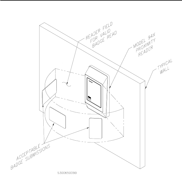
Product Operation: The reader transmits a wake-up field extending
all around the reader (the 941 and 971 generate virtually no back
field). When a badge is presented, energy from the field powers the
electronics inside the badge allowing it to transmit its unique data to
the reader. The reader receives, interprets, and checks the data,
sending only uncorrupted badge data to the microcontroller. Due to
the nature of the wake-up field, the maximum read range will be
realized only if the badge is presented to the reader on an imaginary
semi-circle centered on the reader, as shown below.
FIGURE 15: Badge to Reader Presentation
While the reader will read and send another badge’s data
immediately, the risk of multiple badge reads is reduced by a
Model 94x, 97x Proximity Reader 37
two-second same-badge-send delay.
In the supervised modes, the reader also monitors and reports the
status of a normally closed door contact switch and a normally open
exit request push button.
Application:Intended for areas requiring a moderately high level of
security for controlled access.
Compatibility: Interfaces to all CASI-RUSCO systems.
Reader Technology Types: CASI-RUSCO Proximity Perfect
Read/Write technology and CASI-RUSCO ProxLite Read Only
technology.
Badge Formats: CASI-RUSCO Proximity Perfect badges encoded
with 2801, 2804, 3201, or 40-bit data formats; or CASI-RUSCO
ProxLite and Entrée badges and key tags.
•Mounting: The reader can be mounted directly onto a standard
U.S. electrical gang box (Model 94x onto single-gang box, 97x
onto dual-gang box). The reader can also be mounted directly
onto a hollow wall. A sealing gasket is provided for weather-
resistant outdoor installations. For outdoor installations, where
the reader is mounted in direct exposure to weather, a bead of
silicone caulking should be applied between the reader and the
wall to prevent water from entering the back of the reader. See
“Mounting the Reader” on page 17 for additional details.
Indicators: Red, yellow, and green LEDs, and a beeper are
incorporated into the reader.
•Red LED: Turns on continuously to indicate a tamper in the
Wiegand and F/2F modes. In the supervised modes, the red LED
flashes quickly (every 400 ms) to indicate a tamper condition.
If communications with the microcontroller are lost while in the
supervised modes, the red LED flashes slowly (every 2 seconds).
In both supervised modes, the red LED may also be turned on
and off by the microcontroller to indicate an alarm state. Consult
the appropriate system manual for details on this operation.
•Yellow LED: Normally on when power is applied to the reader.
Blinks off briefly to indicate that a badge has been read and sent
to the microcontroller. Blinks off briefly to indicate that a
keypress has been read and sent to the microcontroller (Models
972 and 973 only).
•Green LED: Indicates that the microcontroller has activated the
door strike. In the unsupervised mode, the green LED flashes
38 Model 94x, 97x Proximity Reader
quickly (every 400 ms) to indicate that the microcontroller has
requested a PIN entry.
•Beeper: The beeper sounds briefly to indicate that a valid badge
has been read and sent to the microcontroller. The beeper sounds
continuously while a key is pressed (Models 972 and 973 only). A
short triple beep sounds every 30 seconds to indicate a reader
tamper. In the normal supervised modes, a short triple beep
every 30 seconds indicates a disruption in communications with
the microcontroller.
In both supervised modes, the beeper may be sounded by the
microcontroller to indicate an alarm state. Consult the
appropriate system manual for details on this operation.
An external device can be connected to all LEDs and the beeper at
connector J1. In this case, the LEDs and beeper can be driven by
thereaderortheexternaldevice.DrivingtheappropriateJ1pin
to a low voltage activates the indicator. This low voltage can be
sensed by the external device even when the indicator is driven
by the reader.
Supervised F/2F Mode Operation: In the supervised modes, the
reader sends badge data or reader status data to the microcontroller
approximately once every second and waits for an acknowledgment
from the microcontroller. The reader continues sending the data
every second until an acknowledgment is received. If an
acknowledgement is not received after the third attempt, the reader
stops reading badges, the red LED starts flashing slowly (every 2
seconds), and a short triple beep sounds every 30 seconds, unless
silent supervised mode is selected. Once the reader receives an
acknowledgment, it begins reading badges again, the beeper stops
sounding and the red LED stops flashing.
Badge Read Operation:Each time the reader sends badge data, the
yellow LED blinks off briefly and the beeper sounds. On systems set
up for PIN entry, the green LED flashes to indicate that keypad data
is expected.
Keypad Operation (Models 972/973 only): The reader sends
each new keypress to the microcontroller and blinks the yellow LED
off. The beeper sounds while a key is pressed. In unsupervised F/2F
mode, the keypad has no function.
Reader Tamper Operation: The 94x/97x Readers incorporate an
internal and external tamper. If the reader is separated from the
backplate, or the reader and backplate are removed from the wall
together, then the reader functions are disabled and a tamper
condition is indicated by a triple beep every 30 seconds. In the
Model 94x, 97x Proximity Reader 39
Wiegand and F/2F modes, the red LED stays on continuously during
a tamper condition (this can be sensed by a low voltage on connector
J1 pin 3). In both supervised modes, the red LED flashes quickly
(every 400 ms) and all communications with the microcontroller are
suspended, taking the reader offline.
Door Contact and Exit Request Inputs: The 94x/97x Readers
have a normally closed door contact switch input and a normally
open exit request switch input. In the supervised modes, the state of
both switch inputs is periodically reported to the microcontroller, but
changes to switch inputs are reported immediately. In the Wiegand
and F/2F modes, these switch inputs have no function.

40 Model 94x, 97x Proximity Reader
NOTES

Model 94x, 97x Proximity Reader 41
NOTES

42 Model 94x, 97x Proximity Reader
NOTES