Cassidian Finland DAH7974 TETRA base station transceiver type TB3 TTRX800 User Manual
Cassidian Finland Oy TETRA base station transceiver type TB3 TTRX800
UserManual.wiki
>
Cassidian Finland
>
DAH7974 User Manual
User manual
Navigation menu
Upload a User Manual
Namespaces
Wiki Guide
HTML
PDF
Info
Views
User Manual
Discussion / Help
Navigation
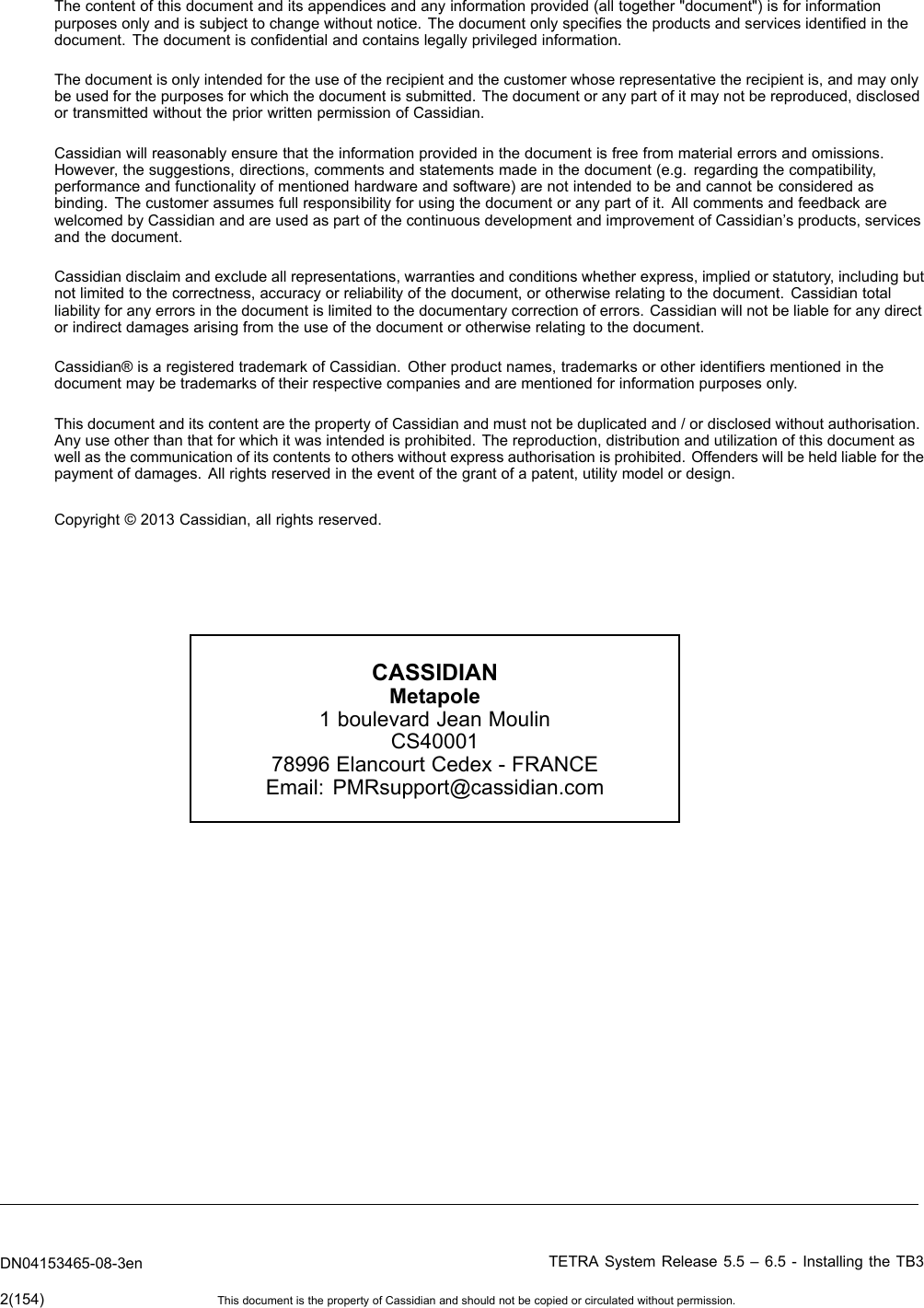
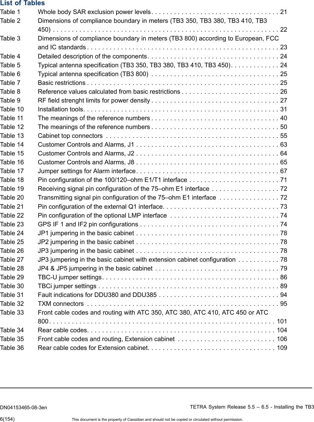


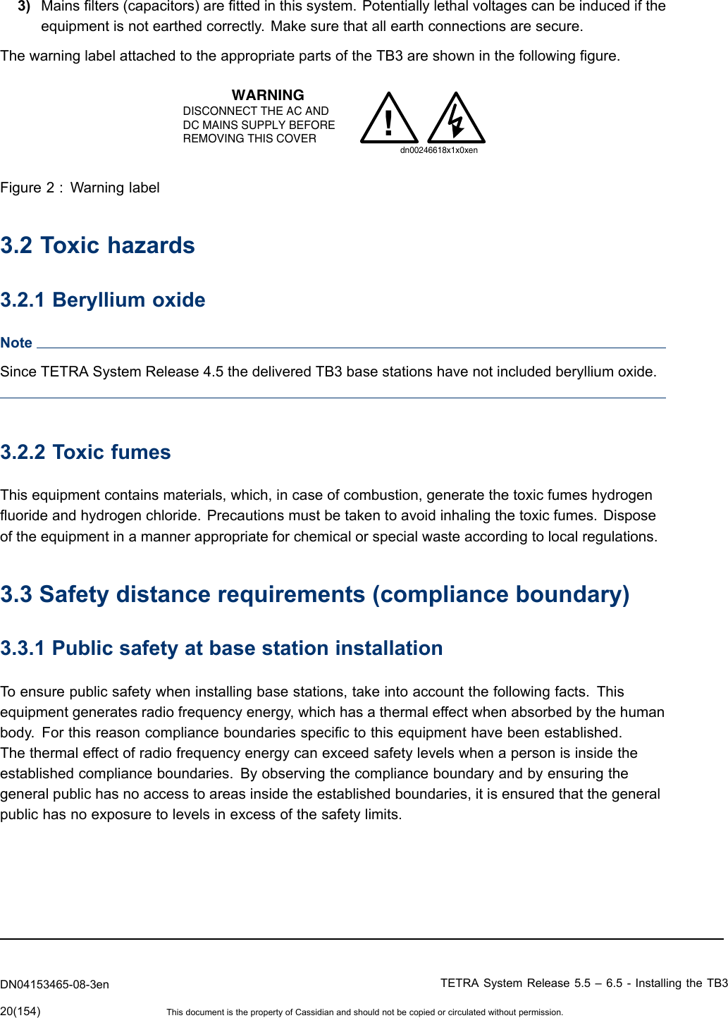
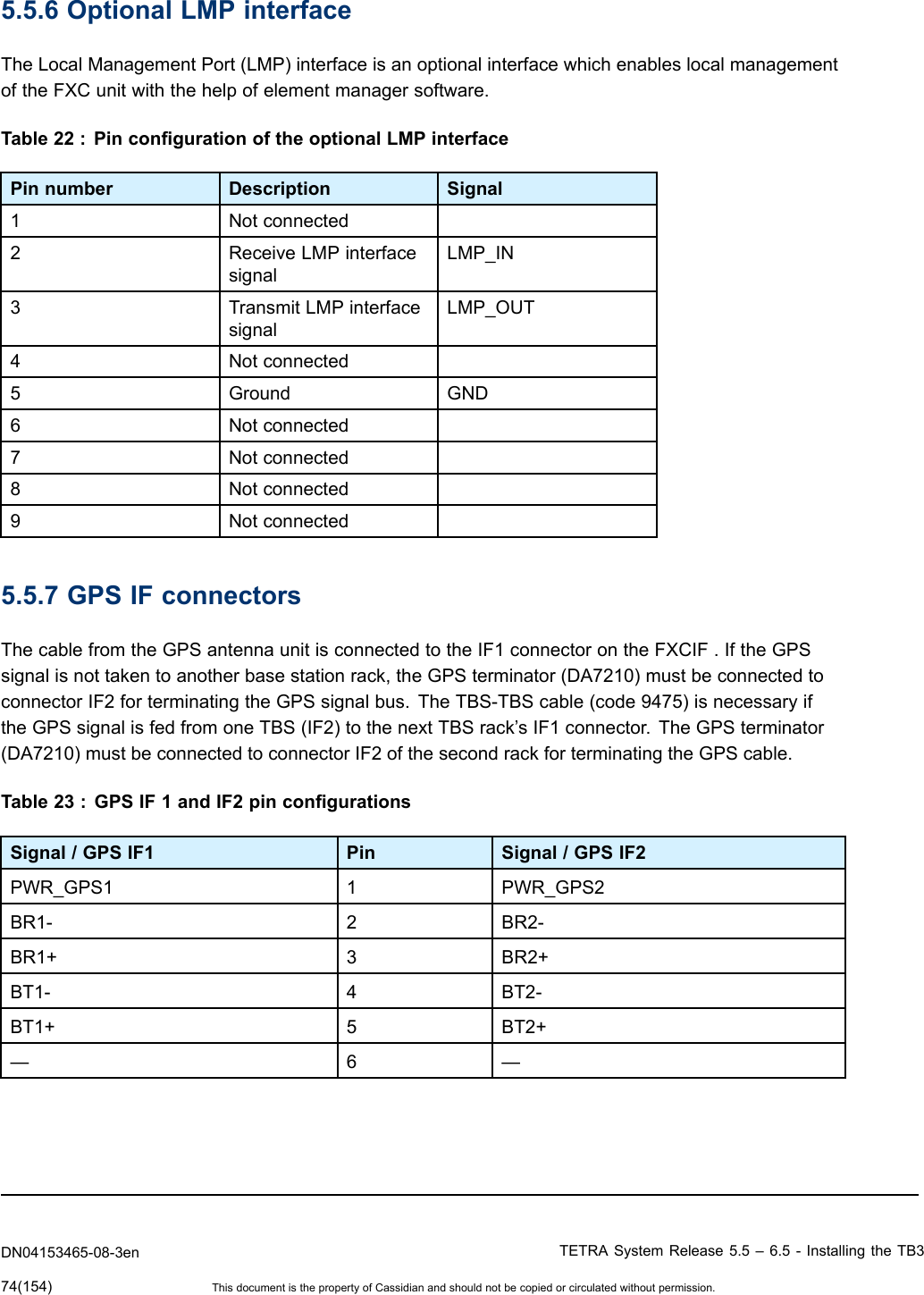
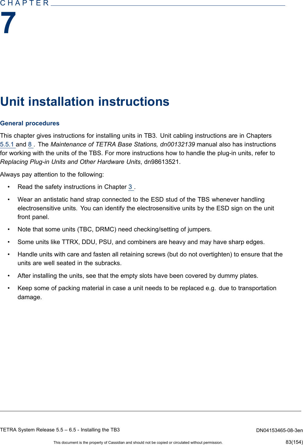
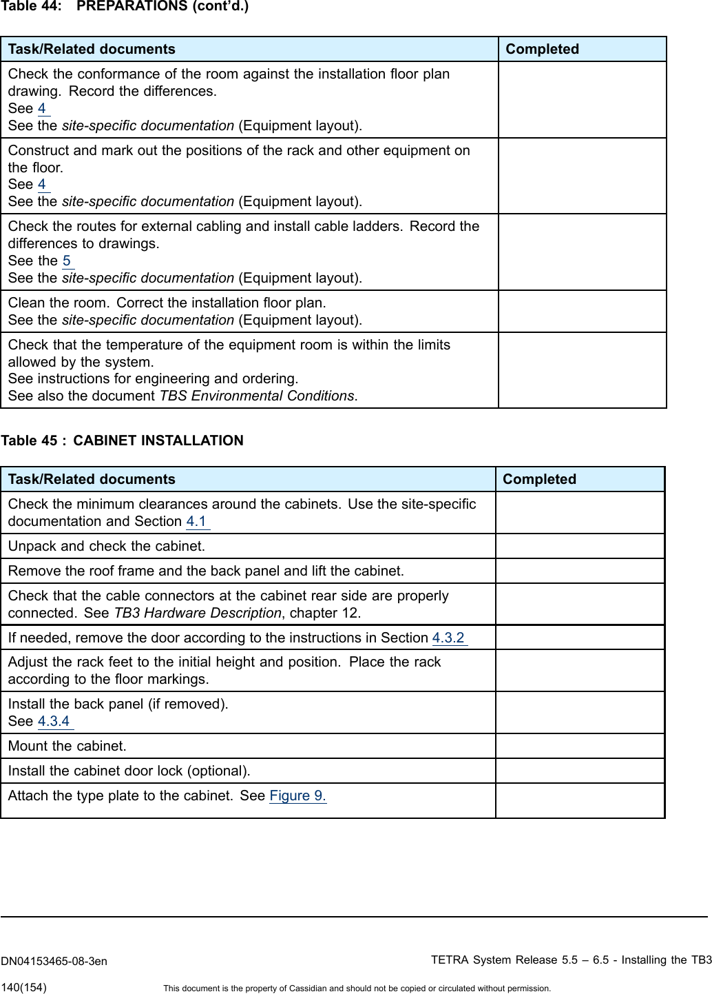
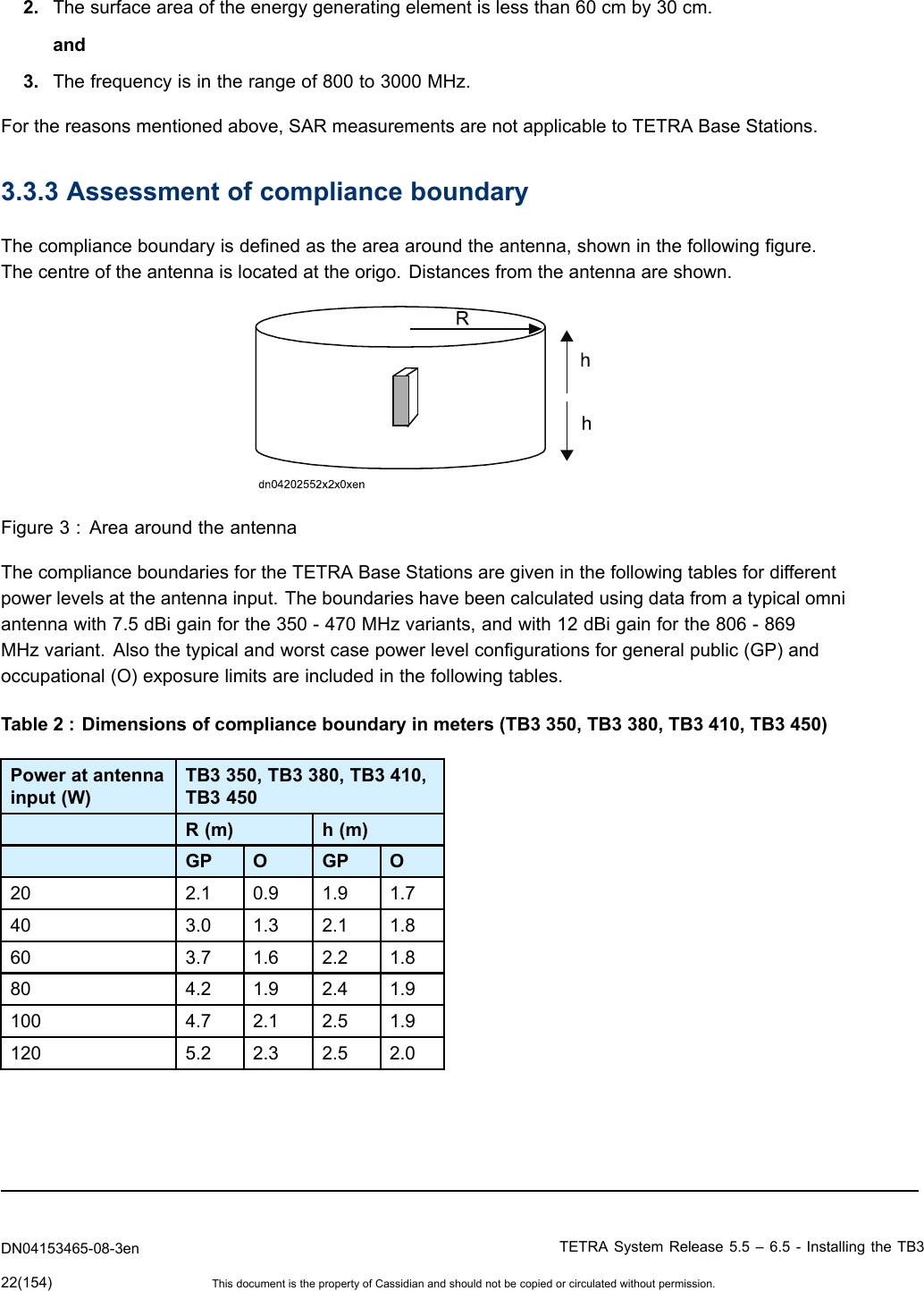
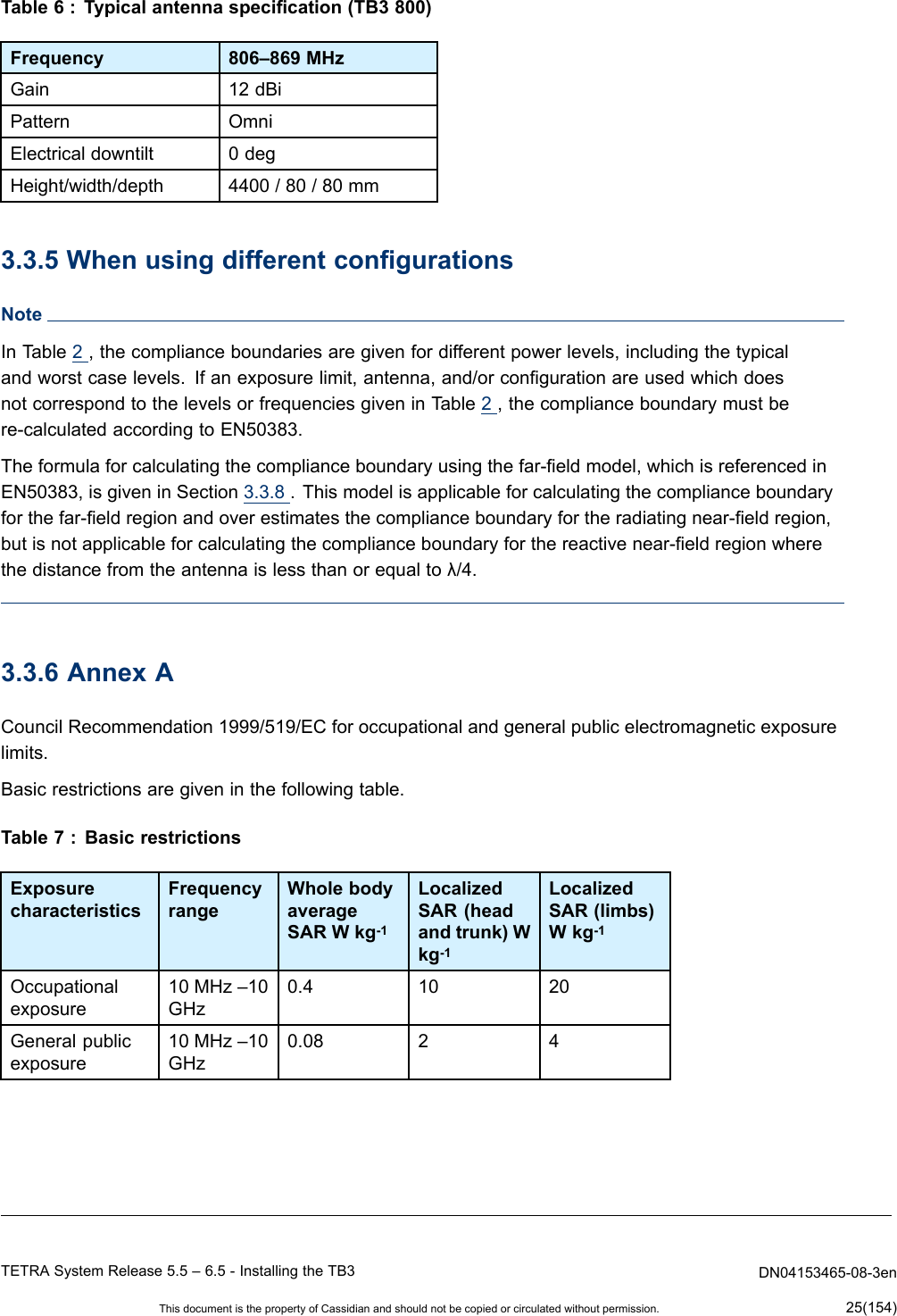
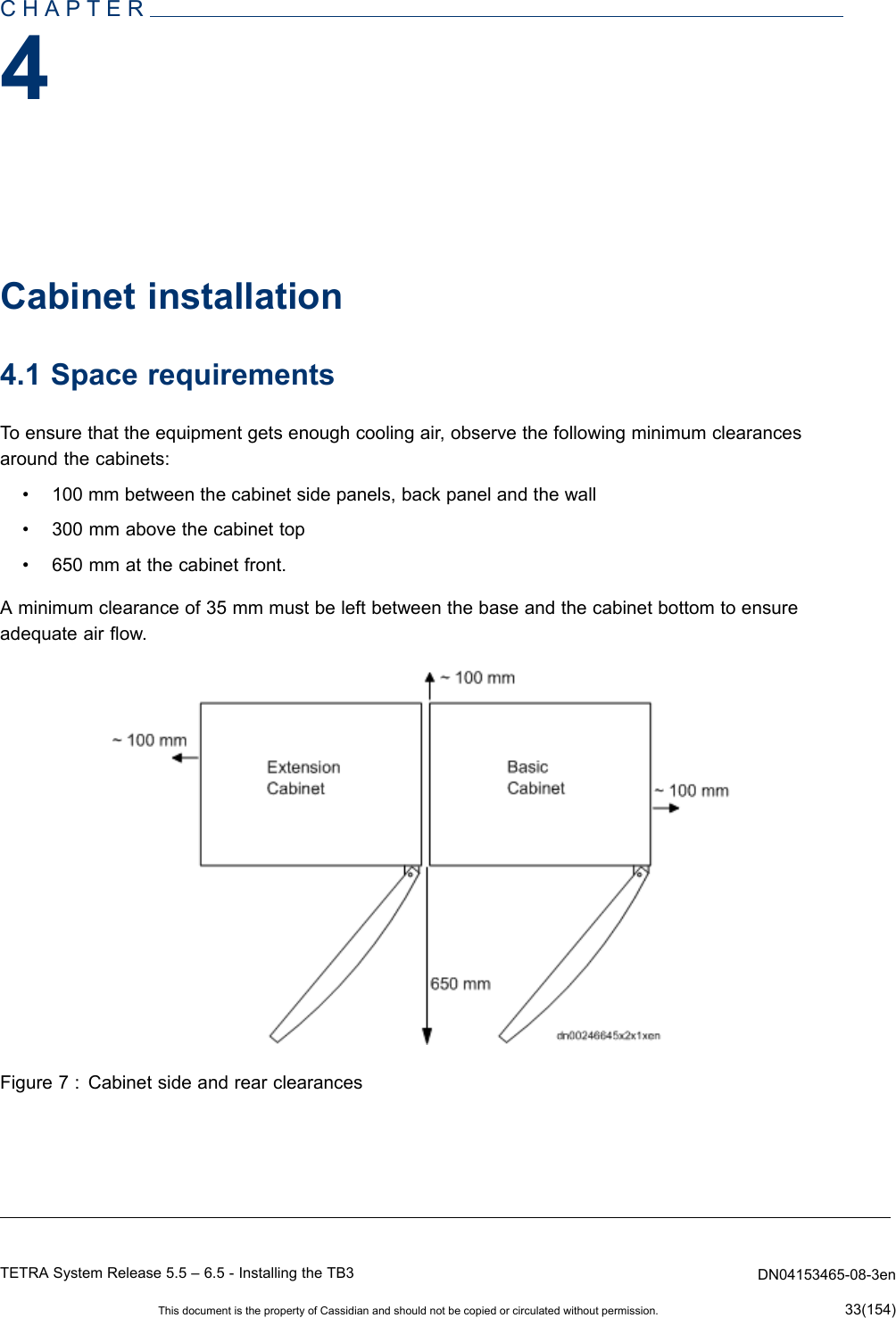
![Toensureinstallersafetywheninstallingbasestations,installationengineersneedtobeawareofthepotentialriskofthethermaleffectsofradiofrequencyenergyandofwhatprecautionstotakeagainstunduerisk.Whenworkingclosetotransmitterantennas,thepropersafetydistancesmustbeobserved.Theminimumsafedistancefromanantennaismeasuredinmetres.WARNINGDonotgoanyclosertoaliveantennathanthecomplianceboundary.Theradiofrequencyenergygeneratedbytheantennaposesaserioushealthrisk.AVERTISSEMENTNepass’approcherd’uneantenneactiveplusprèsquelalimitedeconformité.L’énergieradiofréquencegénéréeparl’antenneposedesérieuxrisquespourlasanté.Whenassessingtheapplicablecomplianceboundaries,EuropeanstandardsEN50383,EN50384,EN50385andCouncilRecommendation1999/519/ECforoccupationalandgeneralpublicelectromagneticexposurelimitshavebeenapplied(seeSection3.3.6).ComplianceboundariesfortheTB3800havealsobeencalculatedaccordingtoFCC1.1310andIndustryCanadaRSS-102requirements(seeTable3andSection3.3.7).3.3.2AssessmentapplyingSARmeasurementsEuropeanstandardsEN50383,EN50384andEN50385donotincludespecicationsforwholebodySpecicabsorptionrate(SAR)measurements.WholebodySARmeasurementsarenotrequiredfortransmittersthathavemaximumoutputpowerlevelstoolowtoresultinexposurelevelsthatcanreachthewholebodySARcompliancelimitsunderanyconditions.WholebodySARexclusionpowerlevelshavebeenbasedonworst-caseassumptions.Fordetails,seethefollowingtable.Table1:WholebodySARexclusionpowerlevelsExposurecategoryMaximumoutputpower(rms)GeneralPublicMaxpower[W]=generalpublicwholebodySARlimit0.08[W/kg]4-yearoldchildmass12.5[kg]=1WOccupationalMaxpower[W]=occupationalwholebodySARlimit0.4[W/kg]16-yearoldworker42[kg]=16.8WLocalizedSARmeasurementcanbeusedonlywhen:1.Theseparationbetweenthephantomandtheoutersurfaceoftheenergygeneratingelementis40cmorless.andTETRASystemRelease5.5–6.5-InstallingtheTB3DN04153465-08-3enThisdocumentisthepropertyofCassidianandshouldnotbecopiedorcirculatedwithoutpermission.21(154)](https://usermanual.wiki/Cassidian-Finland/DAH7974/User-Guide-2055937-Page-21.png)
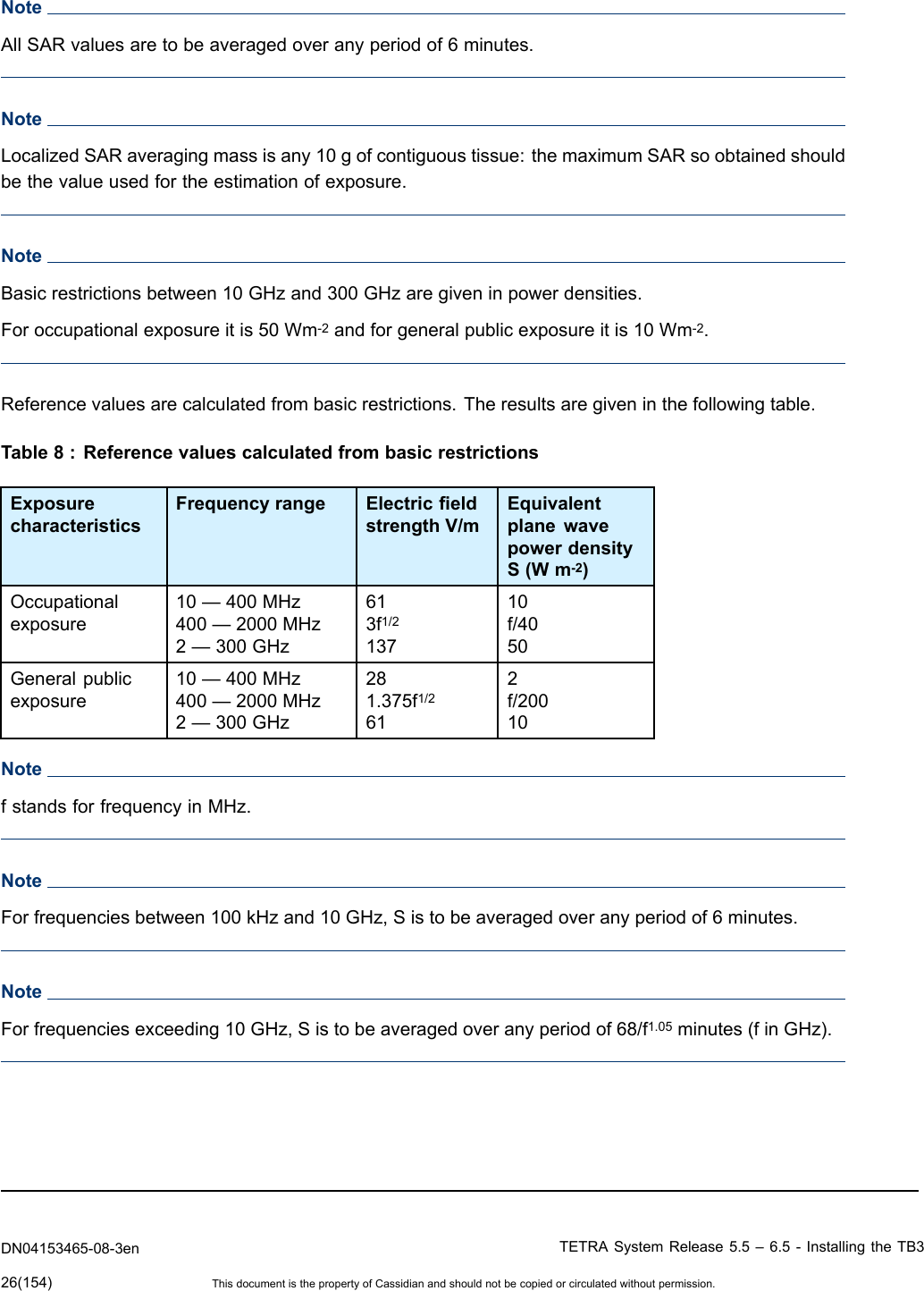
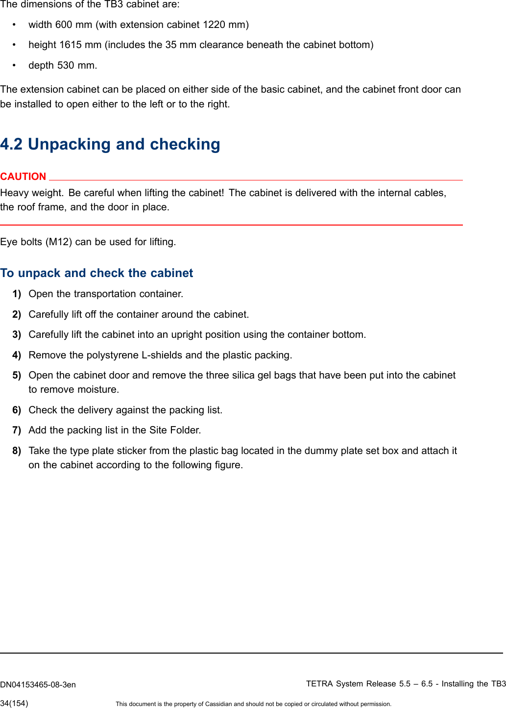


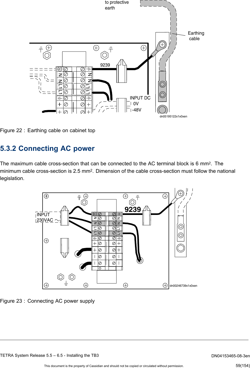
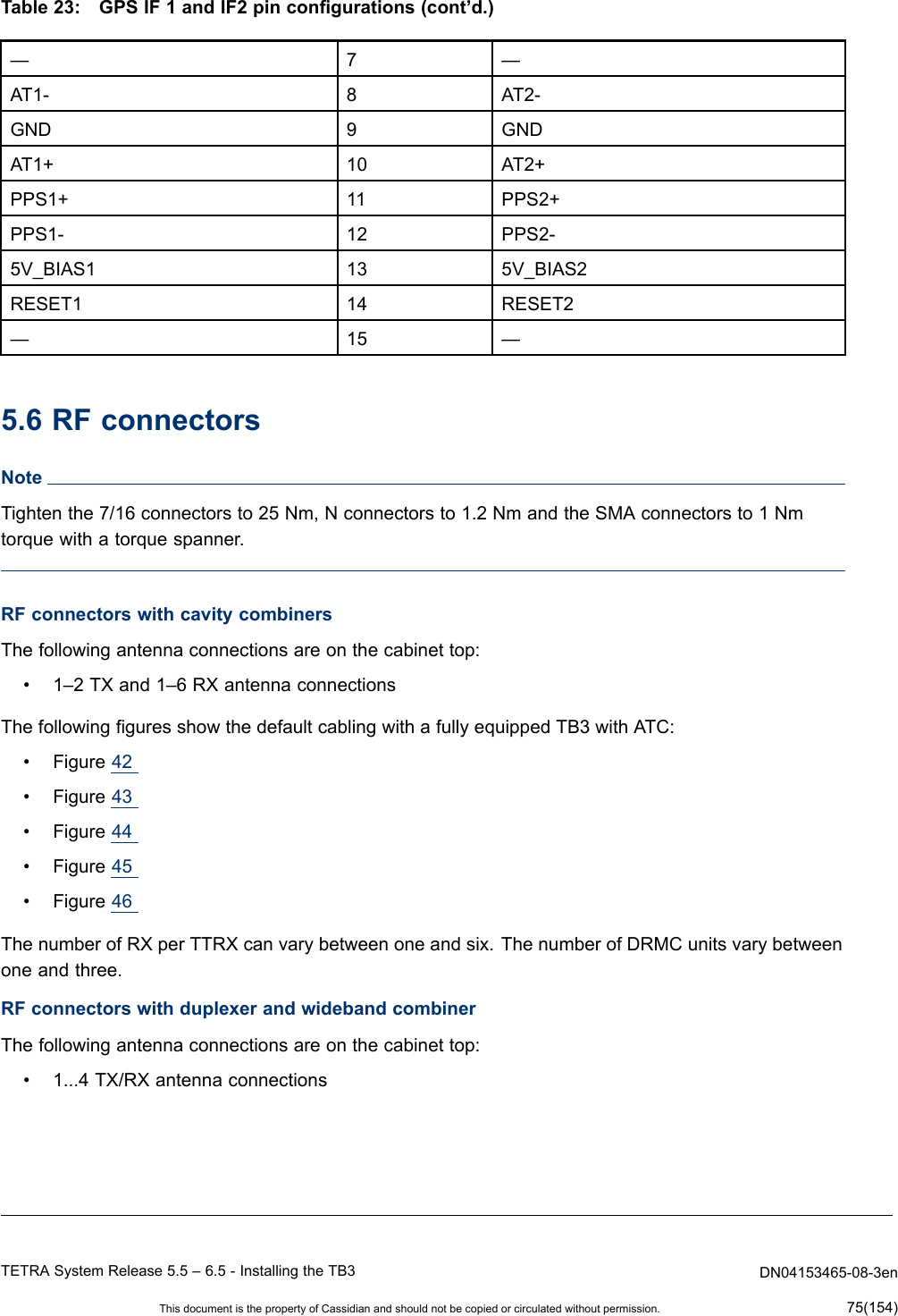
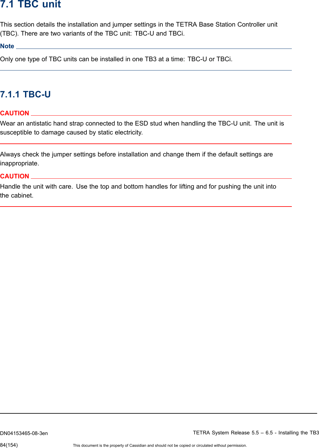
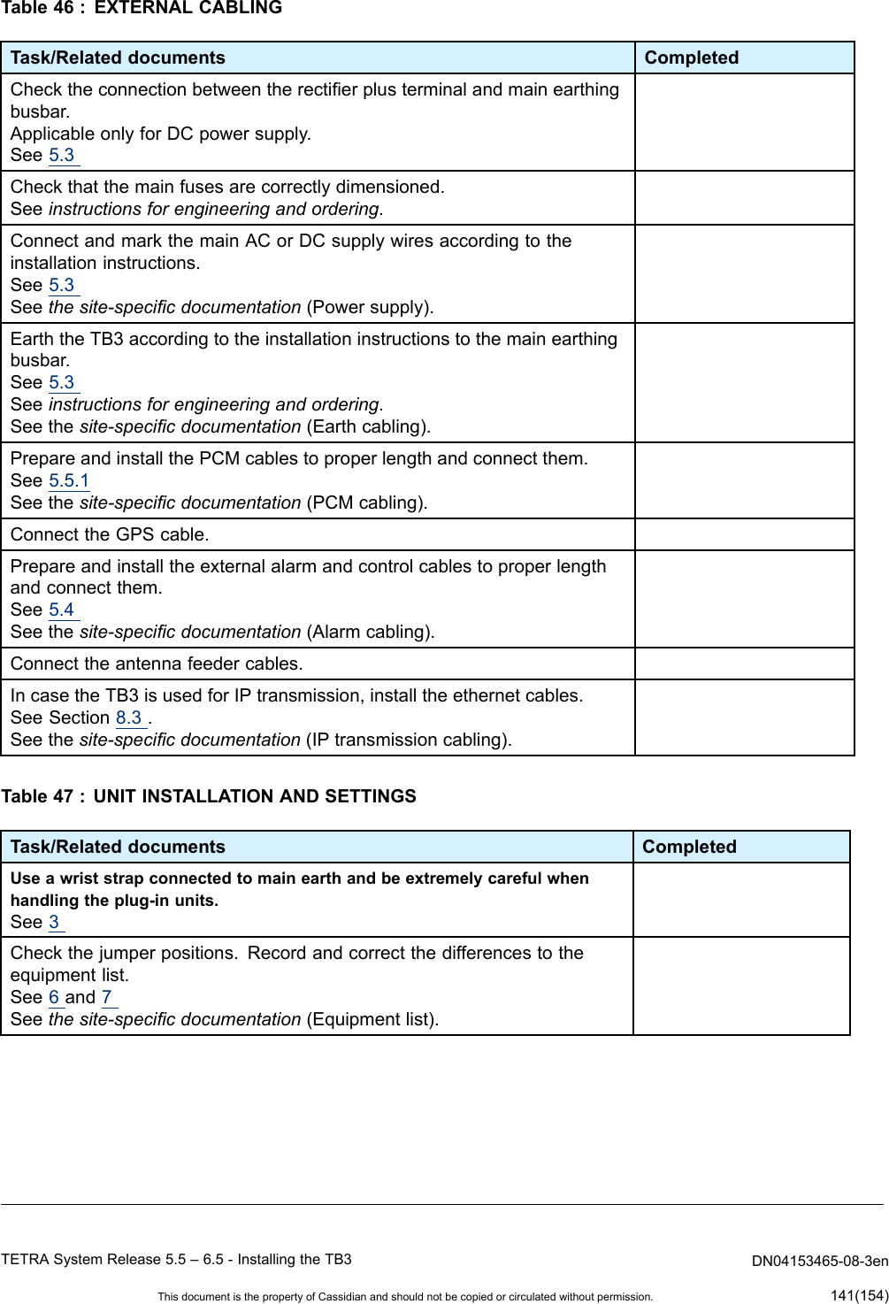
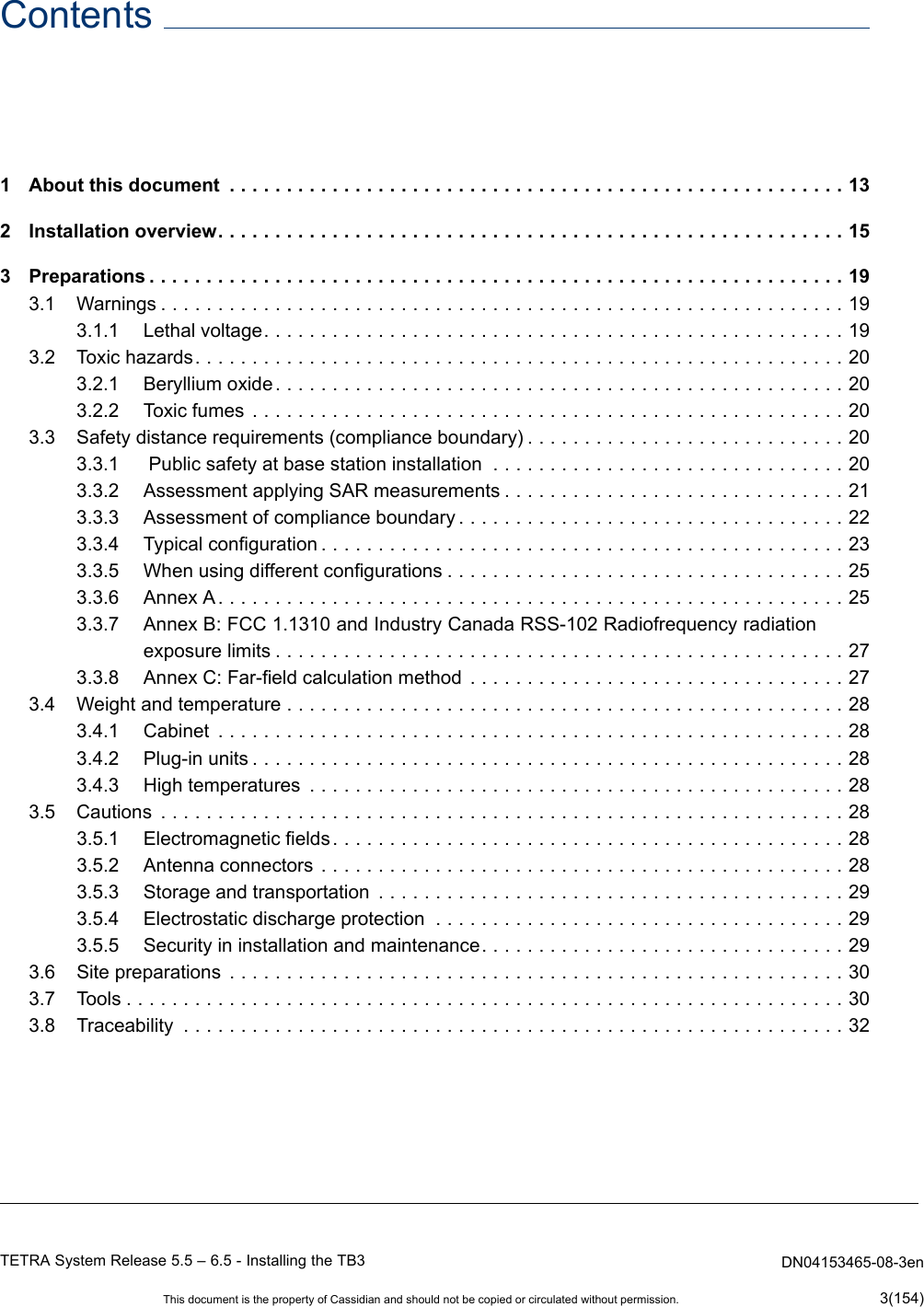
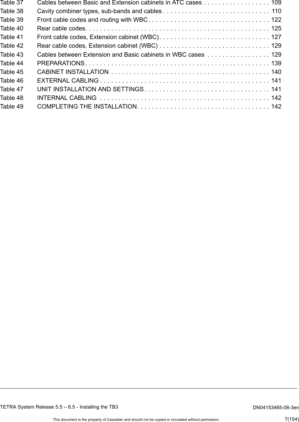
![ToconnecttheACpowertothecabinet1)Checkthatthecabinetisproperlyearthed.2)CutthethreewiresoftheACpowercablesothattheearthwireisabout2cmlongerthantheothertwowires.Stripthewiresfor1cm.3)Inserttheearthwiretotheearthterminalandsecurethewiretotheterminalblockwithascrewdriver.4)Removetheplasticshieldsfromthe[N]and[L1]terminalsandloosenthescrewsoftheterminals.5)Inserttheneutralwiretothe[N]terminalandsecurethewiretotheterminalblockwithascrewdriver.6)Insertthelivewiretothe[L1]terminalandsecurethewiretotheterminalblockwithascrewdriver.7)Securethepowercablewiththecableclamp.8)Replacetheplasticshieldsto[N]and[L1]terminals.5.3.3DCpowersupplyDimensionofthecablecross-sectionmustconformtonationalrequirements.•Themaximumcablecross-sectionthatcanbeconnectedtotheDCterminalblockis25mm2.•Theminimumrecommendedcablecross-sectionis16mm2.Itisalsorecommendedthatfuturecapacity(powerconsumptiongrowth)isusedasaguidelineforselectingthecable.Currentsupto50AshouldbehandledbytheDCinputcabling.AlsocablelossesmustbetakenintoaccountsothattheinputvoltagetotheTB3stayswellwithinspeciedvalues.Approximatevoltagedropfortherst4.5mof16mm2cablewith50Aloadis0.5V.DN04153465-08-3enTETRASystemRelease5.5–6.5-InstallingtheTB360(154)ThisdocumentisthepropertyofCassidianandshouldnotbecopiedorcirculatedwithoutpermission.](https://usermanual.wiki/Cassidian-Finland/DAH7974/User-Guide-2055937-Page-60.png)
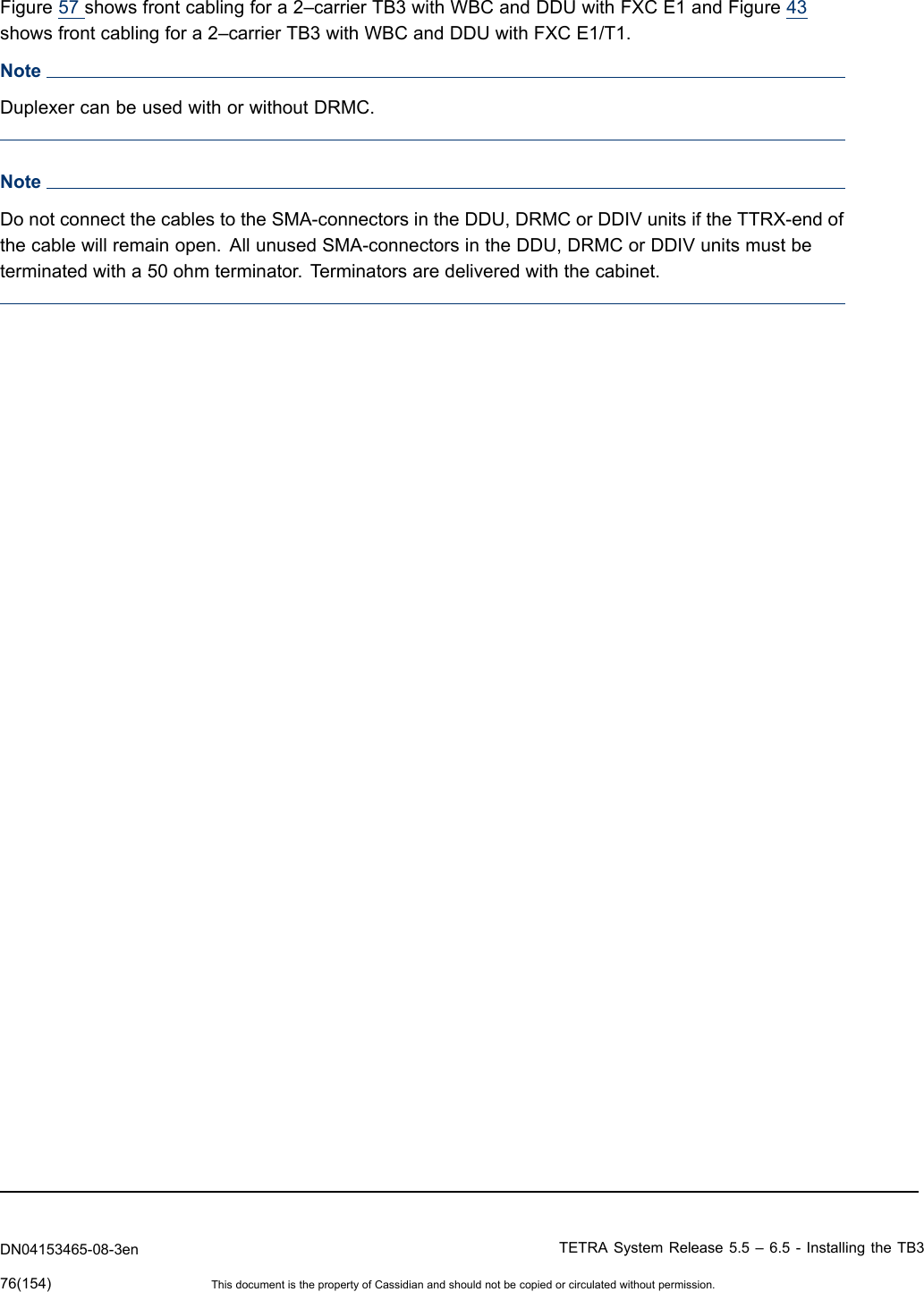
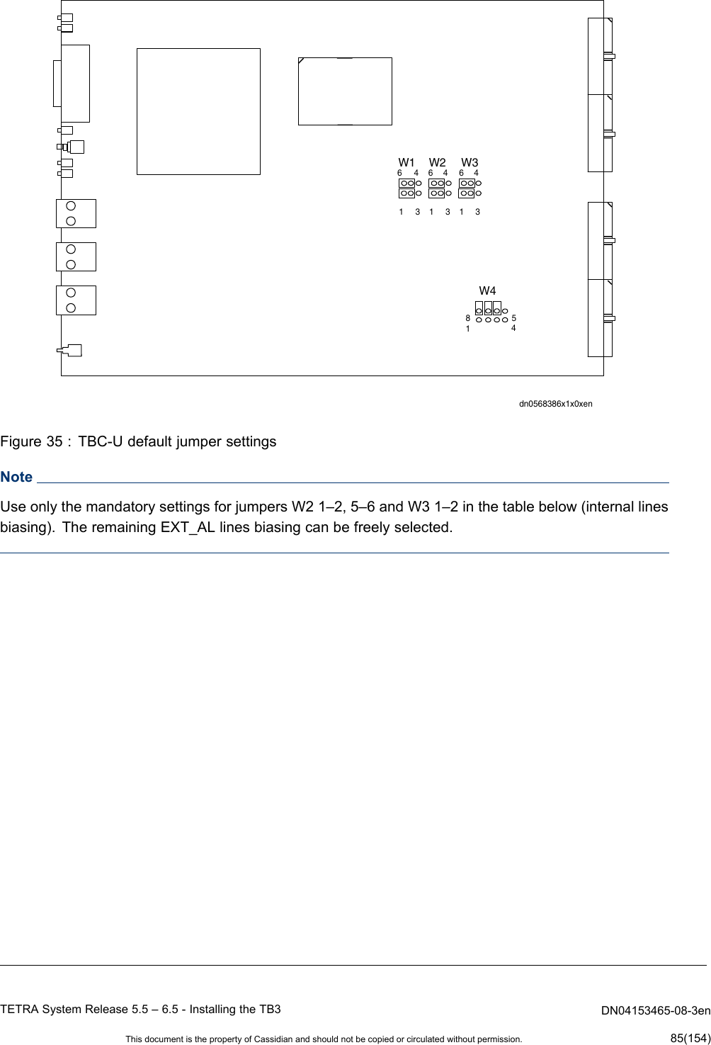
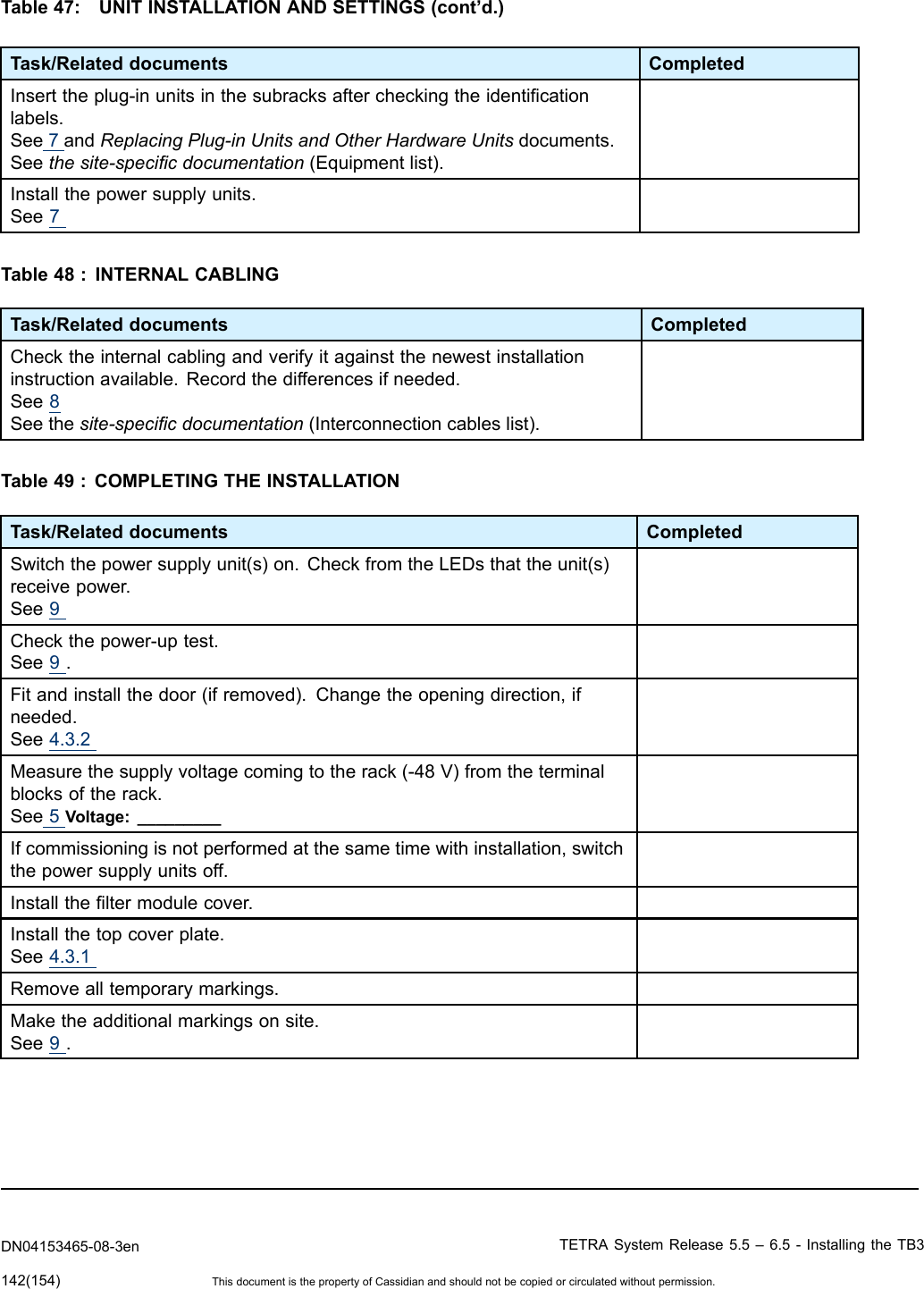
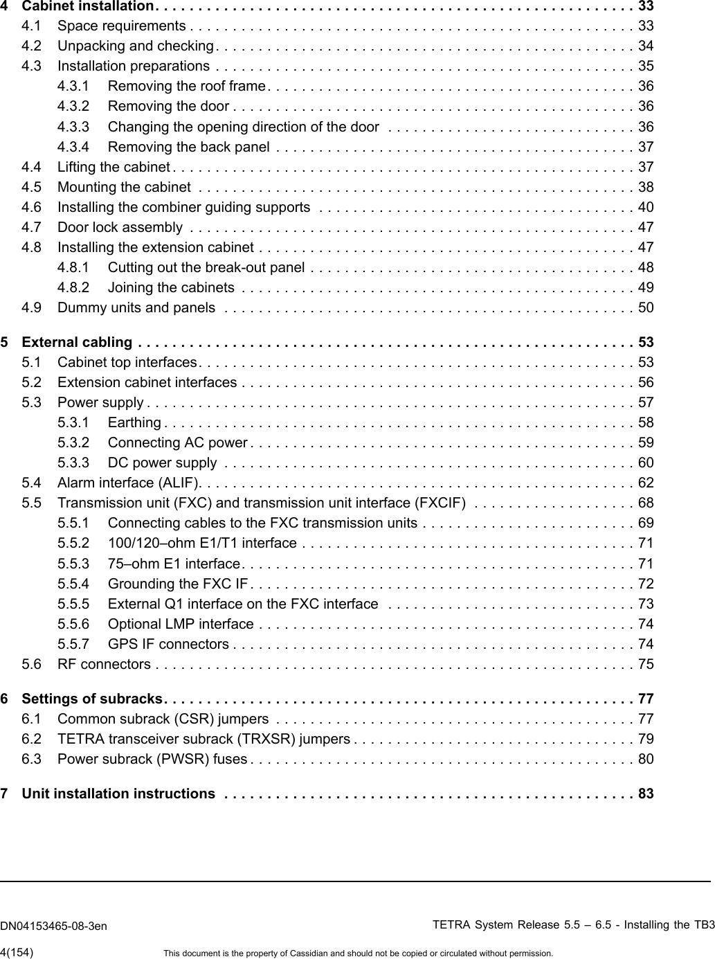
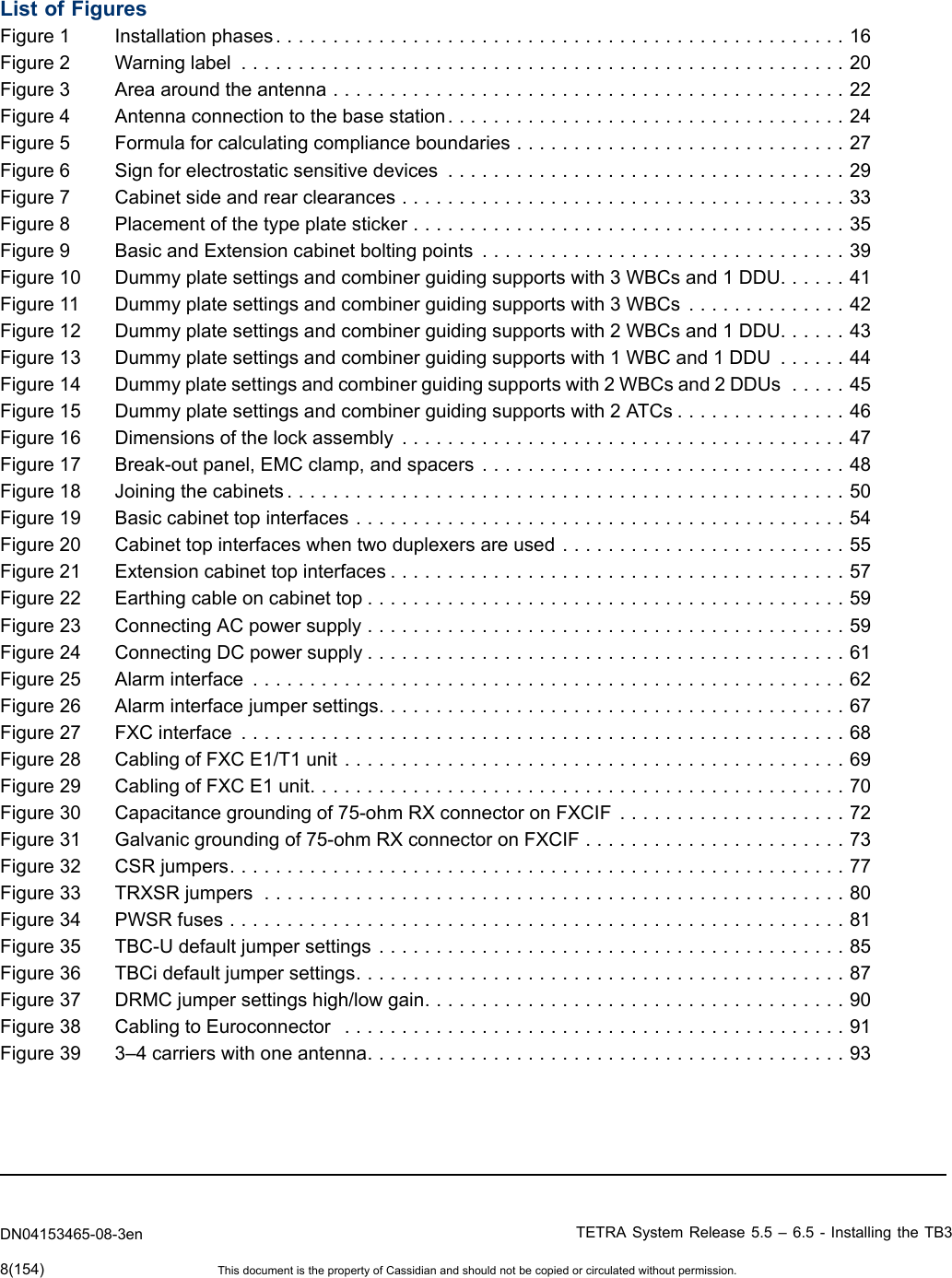
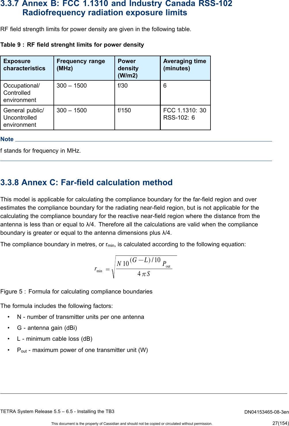
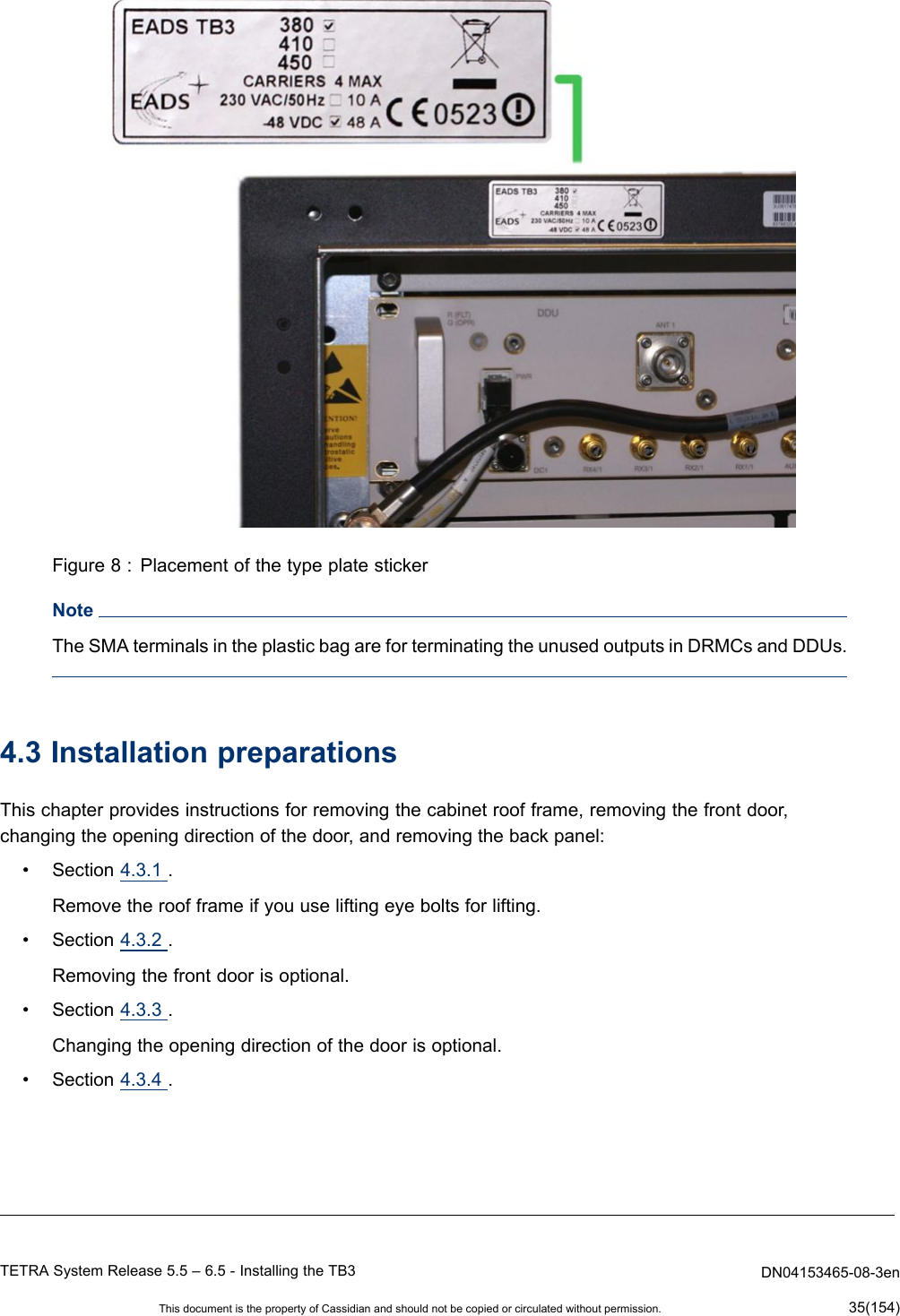
![dn05195134x1x0xenN NNNL1L1L1L1INPUT DC0V-48V9239Figure24:ConnectingDCpowersupplyToconnecttheDCpowertothecabinet1)Checkthatthecabinetisproperlyearthed.2)Stripthe[+]and[-]wiresfor1cm.3)Removetheplasticshieldfromthe[+]and[-]terminalsandloosenthescrewsoftheterminals.4)Insertthenegativewiretothe[-]terminalandsecurethewiretotheterminalblockwithascrewdriver.5)Insertthepositivewiretothe[+]terminalandsecurethewiretotheterminalblockwithascrewdriver.6)Securethewiresbythecableclamp.7)Replacetheplasticshieldstothe[-]and[+]terminals.TETRASystemRelease5.5–6.5-InstallingtheTB3DN04153465-08-3enThisdocumentisthepropertyofCassidianandshouldnotbecopiedorcirculatedwithoutpermission.61(154)](https://usermanual.wiki/Cassidian-Finland/DAH7974/User-Guide-2055937-Page-61.png)