Cassidian Finland DAH7974 TETRA base station transceiver type TB3 TTRX800 User Manual
Cassidian Finland Oy TETRA base station transceiver type TB3 TTRX800
User manual

DEFENDINGWORLDSECURITY
InstallingtheTB3
InstallingtheTB3
TETRASYSTEMRELEASE5.5–6.5
DN04153465-08-3en
08/2013

Thecontentofthisdocumentanditsappendicesandanyinformationprovided(alltogether"document")isforinformation
purposesonlyandissubjecttochangewithoutnotice.Thedocumentonlyspeciestheproductsandservicesidentiedinthe
document.Thedocumentiscondentialandcontainslegallyprivilegedinformation.
Thedocumentisonlyintendedfortheuseoftherecipientandthecustomerwhoserepresentativetherecipientis,andmayonly
beusedforthepurposesforwhichthedocumentissubmitted.Thedocumentoranypartofitmaynotbereproduced,disclosed
ortransmittedwithoutthepriorwrittenpermissionofCassidian.
Cassidianwillreasonablyensurethattheinformationprovidedinthedocumentisfreefrommaterialerrorsandomissions.
However,thesuggestions,directions,commentsandstatementsmadeinthedocument(e.g.regardingthecompatibility,
performanceandfunctionalityofmentionedhardwareandsoftware)arenotintendedtobeandcannotbeconsideredas
binding.Thecustomerassumesfullresponsibilityforusingthedocumentoranypartofit.Allcommentsandfeedbackare
welcomedbyCassidianandareusedaspartofthecontinuousdevelopmentandimprovementofCassidian’sproducts,services
andthedocument.
Cassidiandisclaimandexcludeallrepresentations,warrantiesandconditionswhetherexpress,impliedorstatutory,includingbut
notlimitedtothecorrectness,accuracyorreliabilityofthedocument,orotherwiserelatingtothedocument.Cassidiantotal
liabilityforanyerrorsinthedocumentislimitedtothedocumentarycorrectionoferrors.Cassidianwillnotbeliableforanydirect
orindirectdamagesarisingfromtheuseofthedocumentorotherwiserelatingtothedocument.
Cassidian®isaregisteredtrademarkofCassidian.Otherproductnames,trademarksorotheridentiersmentionedinthe
documentmaybetrademarksoftheirrespectivecompaniesandarementionedforinformationpurposesonly.
ThisdocumentanditscontentarethepropertyofCassidianandmustnotbeduplicatedand/ordisclosedwithoutauthorisation.
Anyuseotherthanthatforwhichitwasintendedisprohibited.Thereproduction,distributionandutilizationofthisdocumentas
wellasthecommunicationofitscontentstootherswithoutexpressauthorisationisprohibited.Offenderswillbeheldliableforthe
paymentofdamages.Allrightsreservedintheeventofthegrantofapatent,utilitymodelordesign.
Copyright©2013Cassidian,allrightsreserved.
CASSIDIAN
Metapole
1boulevardJeanMoulin
CS40001
78996ElancourtCedex-FRANCE
Email:PMRsupport@cassidian.com
DN04153465-08-3enTETRASystemRelease5.5–6.5-InstallingtheTB3
2(154)ThisdocumentisthepropertyofCassidianandshouldnotbecopiedorcirculatedwithoutpermission.

Contents
1Aboutthisdocument......................................................13
2Installationoverview.......................................................15
3Preparations.............................................................19
3.1Warnings............................................................19
3.1.1Lethalvoltage...................................................19
3.2Toxichazards.........................................................20
3.2.1Berylliumoxide..................................................20
3.2.2Toxicfumes....................................................20
3.3Safetydistancerequirements(complianceboundary)............................20
3.3.1Publicsafetyatbasestationinstallation...............................20
3.3.2AssessmentapplyingSARmeasurements..............................21
3.3.3Assessmentofcomplianceboundary..................................22
3.3.4Typicalconguration..............................................23
3.3.5Whenusingdifferentcongurations...................................25
3.3.6AnnexA.......................................................25
3.3.7AnnexB:FCC1.1310andIndustryCanadaRSS-102Radiofrequencyradiation
exposurelimits..................................................27
3.3.8AnnexC:Far-eldcalculationmethod.................................27
3.4Weightandtemperature.................................................28
3.4.1Cabinet.......................................................28
3.4.2Plug-inunits....................................................28
3.4.3Hightemperatures...............................................28
3.5Cautions............................................................28
3.5.1Electromagneticelds.............................................28
3.5.2Antennaconnectors..............................................28
3.5.3Storageandtransportation.........................................29
3.5.4Electrostaticdischargeprotection....................................29
3.5.5Securityininstallationandmaintenance................................29
3.6Sitepreparations......................................................30
3.7Tools...............................................................30
3.8Traceability..........................................................32
TETRASystemRelease5.5–6.5-InstallingtheTB3DN04153465-08-3en
ThisdocumentisthepropertyofCassidianandshouldnotbecopiedorcirculatedwithoutpermission.3(154)

4Cabinetinstallation........................................................33
4.1Spacerequirements....................................................33
4.2Unpackingandchecking.................................................34
4.3Installationpreparations.................................................35
4.3.1Removingtheroofframe...........................................36
4.3.2Removingthedoor...............................................36
4.3.3Changingtheopeningdirectionofthedoor.............................36
4.3.4Removingthebackpanel..........................................37
4.4Liftingthecabinet......................................................37
4.5Mountingthecabinet...................................................38
4.6Installingthecombinerguidingsupports.....................................40
4.7Doorlockassembly....................................................47
4.8Installingtheextensioncabinet............................................47
4.8.1Cuttingoutthebreak-outpanel......................................48
4.8.2Joiningthecabinets..............................................49
4.9Dummyunitsandpanels................................................50
5Externalcabling..........................................................53
5.1Cabinettopinterfaces...................................................53
5.2Extensioncabinetinterfaces..............................................56
5.3Powersupply.........................................................57
5.3.1Earthing.......................................................58
5.3.2ConnectingACpower.............................................59
5.3.3DCpowersupply................................................60
5.4Alarminterface(ALIF)...................................................62
5.5Transmissionunit(FXC)andtransmissionunitinterface(FXCIF)...................68
5.5.1ConnectingcablestotheFXCtransmissionunits.........................69
5.5.2100/120–ohmE1/T1interface.......................................71
5.5.375–ohmE1interface..............................................71
5.5.4GroundingtheFXCIF.............................................72
5.5.5ExternalQ1interfaceontheFXCinterface.............................73
5.5.6OptionalLMPinterface............................................74
5.5.7GPSIFconnectors...............................................74
5.6RFconnectors........................................................75
6Settingsofsubracks.......................................................77
6.1Commonsubrack(CSR)jumpers..........................................77
6.2TETRAtransceiversubrack(TRXSR)jumpers.................................79
6.3Powersubrack(PWSR)fuses.............................................80
7Unitinstallationinstructions................................................83
DN04153465-08-3enTETRASystemRelease5.5–6.5-InstallingtheTB3
4(154)ThisdocumentisthepropertyofCassidianandshouldnotbecopiedorcirculatedwithoutpermission.

7.1TBCunit............................................................84
7.1.1TBC-U........................................................84
7.1.2TBCi.........................................................87
7.2DRMCunitjumpersettings...............................................90
7.3ATCinstallation.......................................................90
7.3.1Troubleshooting.................................................92
7.4WBCandDDUinstallation...............................................92
7.4.1Troubleshooting.................................................94
7.5TXantennamonitoringunit(TXM)..........................................94
8Internalcabling...........................................................97
8.1Cavitycombiners......................................................98
8.1.1Cabinetfrontcabling(4-carrierTB3withATC)...........................98
8.1.2Cabinetrearcabling(4-carrierTB3withATC)...........................102
8.1.3Extensioncabinetfrontcabling.....................................105
8.1.4Extensioncabinetrearcabling......................................107
8.1.5Cablingforalternativecavitycombinertypes...........................109
8.1.5.1Auto-tunedcavitycombiners................................112
8.1.5.2380MHzmanuallytunedcavitycombiner(DA7004)...............113
8.1.5.3410MHzmanuallytunedcavitycombiner(DA7065)...............117
8.2Widebandcombiner(WBC)anddualduplexer(DDU)...........................119
8.2.1Cabinetfrontcabling(2-carrierTB3withWBC)..........................119
8.2.2Rearcabling(WBC).............................................123
8.2.3Extensioncabinetfrontcabling(WBC)................................125
8.2.4Extensioncabinetrearcabling(WBC)................................127
8.2.5Cablingforalternativecongurations.................................130
8.2.5.1Radiofrequency(RF)cabling................................130
8.3IPtransmissioncabling.................................................133
9Completingtheinstallation.................................................137
9.1Power-uptest........................................................137
10Installationchecklist.....................................................139
ATB3backplanewiring.....................................................145
.
TETRASystemRelease5.5–6.5-InstallingtheTB3DN04153465-08-3en
ThisdocumentisthepropertyofCassidianandshouldnotbecopiedorcirculatedwithoutpermission.5(154)

ListofTables.
Table1WholebodySARexclusionpowerlevels..................................21
Table2Dimensionsofcomplianceboundaryinmeters(TB3350,TB3380,TB3410,TB3
450)............................................................22
Table3Dimensionsofcomplianceboundaryinmeters(TB3800)accordingtoEuropean,FCC
andICstandards...................................................23
Table4Detaileddescriptionofthecomponents...................................24
Table5Typicalantennaspecication(TB3350,TB3380,TB3410,TB3450).............24
Table6Typicalantennaspecication(TB3800)..................................25
Table7Basicrestrictions...................................................25
Table8Referencevaluescalculatedfrombasicrestrictions..........................26
Table9RFeldstrenghtlimitsforpowerdensity..................................27
Table10Installationtools....................................................31
Table11Themeaningsofthereferencenumbers..................................40
Table12Themeaningsofthereferencenumbers..................................50
Table13Cabinettopconnectors..............................................55
Table14CustomerControlsandAlarms,J1......................................63
Table15CustomerControlsandAlarms,J2......................................64
Table16CustomerControlsandAlarms,J8......................................65
Table17JumpersettingsforAlarminterface......................................67
Table18Pincongurationofthe100/120–ohmE1/T1interface........................71
Table19Receivingsignalpincongurationofthe75–ohmE1interface..................72
Table20Transmittingsignalpincongurationofthe75–ohmE1interface................72
Table21PincongurationoftheexternalQ1interface...............................73
Table22PincongurationoftheoptionalLMPinterface.............................74
Table23GPSIF1andIF2pincongurations.....................................74
Table24JP1jumperinginthebasiccabinet......................................78
Table25JP2jumperinginthebasiccabinet......................................78
Table26JP3jumperinginthebasiccabinet......................................78
Table27JP3jumperinginthebasiccabinetwithextensioncabinetconguration...........78
Table28JP4&JP5jumperinginthebasiccabinet.................................79
Table29TBC-Ujumpersettings...............................................86
Table30TBCijumpersettings................................................89
Table31FaultindicationsforDDU380andDDU385................................94
Table32TXMconnectors...................................................95
Table33FrontcablecodesandroutingwithATC350,ATC380,ATC410,ATC450orATC
800............................................................101
Table34Rearcablecodes..................................................104
Table35Frontcablecodesandrouting,Extensioncabinet..........................106
Table36RearcablecodesforExtensioncabinet..................................109
DN04153465-08-3enTETRASystemRelease5.5–6.5-InstallingtheTB3
6(154)ThisdocumentisthepropertyofCassidianandshouldnotbecopiedorcirculatedwithoutpermission.

Table37CablesbetweenBasicandExtensioncabinetsinATCcases..................109
Table38Cavitycombinertypes,sub-bandsandcables.............................110
Table39FrontcablecodesandroutingwithWBC.................................122
Table40Rearcablecodes..................................................125
Table41Frontcablecodes,Extensioncabinet(WBC)..............................127
Table42Rearcablecodes,Extensioncabinet(WBC)..............................129
Table43CablesbetweenExtensionandBasiccabinetsinWBCcases.................129
Table44PREPARATIONS..................................................139
Table45CABINETINSTALLATION...........................................140
Table46EXTERNALCABLING..............................................141
Table47UNITINSTALLATIONANDSETTINGS..................................141
Table48INTERNALCABLING..............................................142
Table49COMPLETINGTHEINSTALLATION....................................142
TETRASystemRelease5.5–6.5-InstallingtheTB3DN04153465-08-3en
ThisdocumentisthepropertyofCassidianandshouldnotbecopiedorcirculatedwithoutpermission.7(154)

ListofFigures.
Figure1Installationphases..................................................16
Figure2Warninglabel.....................................................20
Figure3Areaaroundtheantenna.............................................22
Figure4Antennaconnectiontothebasestation...................................24
Figure5Formulaforcalculatingcomplianceboundaries.............................27
Figure6Signforelectrostaticsensitivedevices...................................29
Figure7Cabinetsideandrearclearances.......................................33
Figure8Placementofthetypeplatesticker......................................35
Figure9BasicandExtensioncabinetboltingpoints................................39
Figure10Dummyplatesettingsandcombinerguidingsupportswith3WBCsand1DDU......41
Figure11Dummyplatesettingsandcombinerguidingsupportswith3WBCs..............42
Figure12Dummyplatesettingsandcombinerguidingsupportswith2WBCsand1DDU......43
Figure13Dummyplatesettingsandcombinerguidingsupportswith1WBCand1DDU......44
Figure14Dummyplatesettingsandcombinerguidingsupportswith2WBCsand2DDUs.....45
Figure15Dummyplatesettingsandcombinerguidingsupportswith2ATCs...............46
Figure16Dimensionsofthelockassembly.......................................47
Figure17Break-outpanel,EMCclamp,andspacers................................48
Figure18Joiningthecabinets.................................................50
Figure19Basiccabinettopinterfaces...........................................54
Figure20Cabinettopinterfaceswhentwoduplexersareused.........................55
Figure21Extensioncabinettopinterfaces........................................57
Figure22Earthingcableoncabinettop..........................................59
Figure23ConnectingACpowersupply..........................................59
Figure24ConnectingDCpowersupply..........................................61
Figure25Alarminterface....................................................62
Figure26Alarminterfacejumpersettings.........................................67
Figure27FXCinterface.....................................................68
Figure28CablingofFXCE1/T1unit............................................69
Figure29CablingofFXCE1unit...............................................70
Figure30Capacitancegroundingof75-ohmRXconnectoronFXCIF....................72
Figure31Galvanicgroundingof75-ohmRXconnectoronFXCIF.......................73
Figure32CSRjumpers......................................................77
Figure33TRXSRjumpers...................................................80
Figure34PWSRfuses......................................................81
Figure35TBC-Udefaultjumpersettings.........................................85
Figure36TBCidefaultjumpersettings...........................................87
Figure37DRMCjumpersettingshigh/lowgain.....................................90
Figure38CablingtoEuroconnector............................................91
Figure393–4carrierswithoneantenna..........................................93
DN04153465-08-3enTETRASystemRelease5.5–6.5-InstallingtheTB3
8(154)ThisdocumentisthepropertyofCassidianandshouldnotbecopiedorcirculatedwithoutpermission.

Figure40TX-antennamonitoringunit(TXM)......................................95
Figure41Cablecodelabel...................................................97
Figure42Frontcablingfora4-carrierTB3withATC(FXCE1).........................99
Figure43Frontcablingfora4-carrierTB3withATC(FXCE1/T1)......................100
Figure44Rearcabling.....................................................103
Figure45Frontcablingofextensioncabinet(examplefor390–396MHzrange)............105
Figure46Extensioncabinetrearcabling........................................108
Figure47RFcablingbetweenAuto-tunedcavitycombinersandTX-antennaconnector:4-carrier
conguration.....................................................112
Figure48RFcablingbetweenAuto-tunedcavitycombinersandTX-antennaconnector:6-carrier
conguration.....................................................112
Figure49RFcablingbetweenAuto-tunedcavitycombinersandTX-antennaconnector:8-carrier
conguration.....................................................113
Figure50380MHzmanuallytunedcavitycombinercables...........................114
Figure51RFcablingbetweenmanuallytunedCB380andTX-antennaconnector:4-carrier
conguration.....................................................115
Figure52RFcablingbetweenmanuallytunedCB380andTX-antennaconnector:6-carrier
conguration....................................................116
Figure53RFcablingbetweenmanuallytunedCB380andTX-antennaconnector:8-carrier
conguration....................................................116
Figure54RFcablingbetweenmanuallytunedCB410andTX-antennaconnector:4-carrier
conguration.....................................................117
Figure55RFcablingbetweenmanuallytunedCB410andTX-antennaconnector:6-carrier
conguration.....................................................118
Figure56RFcablingbetweenmanuallytunedCB410andTX-antennaconnector:8-carrier
conguration.....................................................118
Figure57Cabinetfrontcablingfor2-carrierTB3withWBC(FXCE1)...................120
Figure58Cabinetfrontcablingfor2-carrierTB3withWBC(FXCE1/T1).................121
Figure59Rearcabling(WBC)................................................124
Figure60Extensioncabinetfrontcabling(WBC),oneDDIV..........................126
Figure61Extensioncabinetrearcabling(WBC),threeDDIVs.........................128
Figure62WBCcongurations,oneantenna......................................131
Figure63WBCcongurations,2antennas.......................................132
Figure64WBCcongurations,road............................................133
Figure65CablingbetweenTBCiandbasic-cabinettop-plateinterfaces(IPtransmission).....135
Figure66Basiccabinet,commonsubrack,connectorsforP15,P16,P18andX1,X2........146
Figure67Basiccabinet,commonsubrack,connectorsforP13andP14.................147
Figure68Basicorextensioncabinet,TTRXsubrack,connectorforP5:cablepointingup.....148
Figure69Basiccabinet,powersubrack,connectorsforP9...........................149
Figure70Basicandextensioncabinets,connectorsforfans:cablespointingleft...........150
TETRASystemRelease5.5–6.5-InstallingtheTB3DN04153465-08-3en
ThisdocumentisthepropertyofCassidianandshouldnotbecopiedorcirculatedwithoutpermission.9(154)
DOCUMENTAMENDMENTS
VERSIONDATECOMMENTSCHAPTERUPDATED
08-308/2013UpdatedforTB3800FCCapproval.3.3.1
3.3.3
3.3.8
08-205/2013FCC1.1310andIndustryCanadaRSS-102
Radiofrequencyradiationexposurelimitsadded.
3.3
08-103/2013Customeralarms24-35(J3)changedto(J8).5.4
InformationaddedaboutTB3TBCisupportforIP
transmission.
Sections1,8.1.1,
8.2.1,8.3,T ables
33,39,Figure65
Instructionsaddedfortakingcarethatthebackplane
connectorsarepluggedintherightway.
Sections8.1.4,
8.2.4andAppendix
A
TBCiadded.Figures19,20,21,
25,27,36,T ables
13,33,Sections
7.1,7.1.2
Correctedcablecodes:changed9726as9762Figures44,59,61
,Table43
Correctedcablecode:changed9721as9761Table40
07-108/2011
Minormodications.Throughout
07-002/2009ExtendedTB3alarmsaddedandillustrationsupdated
tocorrespondtothecurrentcabinetversion.
4,5,6
References
1.TETRASystem:Auto-tunedCombinersforTBS,dn00132115
2.TETRASystem:CommissioningtheTB3,dn04153477
3.TETRASystem:FXCE1andE1/T1TransmissionUnitDescriptionforTETRA,dn05100057
4.TETRASystem:Glossary,dn00126469
5.TETRASystem:GuidelinesforInstallingtheGPSUnit,dn00126909
6.TETRASystem:GuidetoTETRADocumentation,dn00126445
7.TETRASystem:InstallingandOperatingtheEADSTBSWinMMI,dn00274177
8.TETRASystem:MaintenanceofTETRABaseStations,dn00132139
DN04153465-08-3enTETRASystemRelease5.5–6.5-InstallingtheTB3
10(154)ThisdocumentisthepropertyofCassidianandshouldnotbecopiedorcirculatedwithoutpermission.

9.TETRASystem:TBSEnvironmentalConditions,dn00132142
10.TETRASystem:TB3HardwareDescription,dn04161675
11.TETRASystem:TB3MMIReferenceManual,dn0526038
12.TETRASystem:TB3ProductDescription,dn04102617
TETRASystemRelease5.5–6.5-InstallingtheTB3DN04153465-08-3en
ThisdocumentisthepropertyofCassidianandshouldnotbecopiedorcirculatedwithoutpermission.11(154)

PAGEINTENTIONALLYLEFTBLANK
DN04153465-08-3enTETRASystemRelease5.5–6.5-InstallingtheTB3
12(154)ThisdocumentisthepropertyofCassidianandshouldnotbecopiedorcirculatedwithoutpermission.

CHAPTER
1
Aboutthisdocument
ThepurposeofthisdocumentistogiveinstructionsfortheinstallationoftheTETRABaseStationTB3
andtoensurethatinstallationiscarriedoutcorrectly.Descriptionsofantenna,powerequipment,and
otherauxiliarysysteminstallationsarenotincludedinthisdocument.
CassidianherebydeclaresthatthisTB3isincompliancewiththeessentialrequirementsandother
relevantprovisionsofDirective1999/5/EC.
Note
CablinginstructionsfortheATC8004–channel150kHz(DA7938)canbefoundfromthedocument
Auto-tunedCombinersforTBS,dn00132115.
Note
TheTB3TBCisupportsIPtransmissionfromtheTETRASystemRelease6.5onwards.
Howtousethisdocument
Thismanualprovidesthefollowinginformation:
•Chapter1Aboutthisdocument(thischapter)introducesthestructureofthedocument.
•Chapter2givesanoverviewoftheinstallationphasesandtheirpurpose.
•Chapter3liststhepreparationsofthesiteandequipmentincludingthesafetyprecautions.
•Chapter4givesinstallationinstructionsforthecabinets.
•Chapter5givesinstructionsforconnectingearthing,powersupply,transmission,GPS,customer
alarms,customercontrolsandantennafeedercablestothecabinet.
•Chapter6describesthejumpersoftheCSRandTRXSR,aswellasPWSRfuses.
•Chapter7detailstheunitinstallationandjumpersettingsoftheTBCandDRMC.
•Chapter8givesinstructionsforconnectingandcheckingthecablingwithinthecabinet.
TETRASystemRelease5.5–6.5-InstallingtheTB3DN04153465-08-3en
ThisdocumentisthepropertyofCassidianandshouldnotbecopiedorcirculatedwithoutpermission.13(154)

•Chapter9describesthecompletiontasksrelatedtotheinstallationoftheTB3.
•Chapter10givesanexampleofaninstallationchecklist.
•AppendixAprovidesinstructionsforwiringtheTB3backplanetomakesurethattheconnectors
arepluggedintherightway.
TheGlossarysectionexplainsthecentraltermsandconceptsusedinthisdocumentaswellasthe
abbreviations.ThefullversionoftheglossaryisprovidedasaseparatedocumentTETRASystem:
Glossary,dn0126469.
Wewelcomeanysuggestionsforfurtherimprovementofthisdocument.Also,shouldyoundany
errorsoromissionsinthisdocument,pleaseforwardyourcommentstoyournearestCassidian
representativeortothee-mailaddresstetra.cudo@cassidian.com.
DN04153465-08-3enTETRASystemRelease5.5–6.5-InstallingtheTB3
14(154)ThisdocumentisthepropertyofCassidianandshouldnotbecopiedorcirculatedwithoutpermission.

CHAPTER
2
Installationoverview
ThepurposeofTB3installationisto:
•Checkthedelivery.
•InstalltheTB3onthesite.
•SettheTB3andthesitereadyforcommissioning.
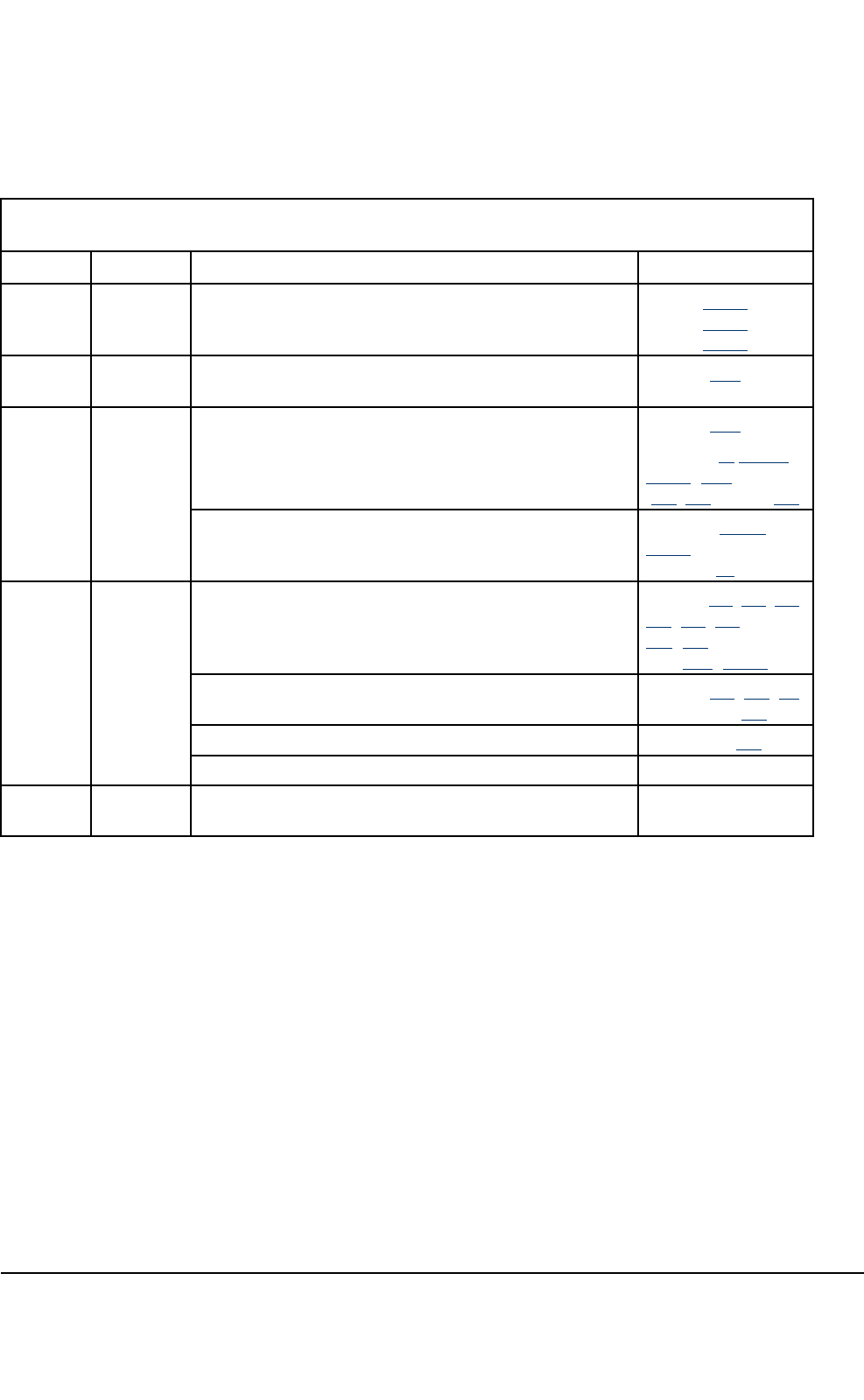
TheTB3isdeliveredwithplug-inunitsremovedfromthesubracks.Figure1liststhephasesofthe
installation,whichareclariedbelow.
TETRASystemRelease5.5–6.5-InstallingtheTB3DN04153465-08-3en
ThisdocumentisthepropertyofCassidianandshouldnotbecopiedorcirculatedwithoutpermission.15(154)
Dn05220799x2x0en
1
Preparations
2
Cabinetinstallation
3
Settingsofsubracks
5
Unitinstallation
6
Internalcabling
7
Completinginstallation
4
Settingsofsubracks
3
Settingsofsubracks
3
Externalcabling
Figure1:Installationphases
Preparations
Purpose:
Checkingthatallthematerialanddocumentsareavailableandtheworkcanstart.Gettingfamiliarwith
theWarningsandCautionssectionsofthismanual.
SeeChapter3.
Cabinetinstallation
Purpose:
Unpacking,checking,andinstallingtheTB3.
SeeChapter4.
Externalcabling
Purpose:
DN04153465-08-3enTETRASystemRelease5.5–6.5-InstallingtheTB3
16(154)ThisdocumentisthepropertyofCassidianandshouldnotbecopiedorcirculatedwithoutpermission.

Connectingearthing,powersupply,transmission,GPS,customeralarms,customercontrolsand
antennafeedercablestothecabinet.
SeeChapter5.
Settingsofsubracks
Purpose:
JumperingtheCSRandTRXSR,resettingthePWSRfuses.
SeeChapter6.
Unitinstallation
Purpose:
Checkingthejumpersettingsofunitsandinstallingtheplug-inunitstothecabinet.
SeeChapter7.
Internalcabling
Purpose:
Connectingandcheckingthecablingwithinthecabinet.
SeeChapter8.
Completingtheinstallation
Purpose:
Finishinginstallationandsite-specicdocumentsandcleaningthesite.
SeeChapter9.
TETRASystemRelease5.5–6.5-InstallingtheTB3DN04153465-08-3en
ThisdocumentisthepropertyofCassidianandshouldnotbecopiedorcirculatedwithoutpermission.17(154)

PAGEINTENTIONALLYLEFTBLANK
DN04153465-08-3enTETRASystemRelease5.5–6.5-InstallingtheTB3
18(154)ThisdocumentisthepropertyofCassidianandshouldnotbecopiedorcirculatedwithoutpermission.

CHAPTER
3
Preparations
3.1Warnings
Thischapterdetailstherecommendedsafetyprecautionstobefollowedwhenworkingwiththe
TETRABaseStationTB3.
Thesafetyguidelinesaredesignedinthefollowingway:
•Warningsalertthereadertodangerswhichmaycausephysicalinjuryorillhealthinanyform,
potentiallyincludinglossoflife.
•Cautionsareusedtodenotepossibledamagetoequipmentbutnotdangerstopersonnel.
Installation,commissioning,integration,andmaintenancemeasuresconcerningtheTB3smaybe
performedonlybyproperlytrainedandauthorizedpersonnel.Theequipmentshouldbeinstalledand
locatedsothatonlyauthorizedpersonnelhaveaccesstoitspotentiallydangerousparts.
3.1.1Lethalvoltage
Potentiallylethalvoltagesarepresentwithinthissystem.Allpersonswhoperformanymeasureson
thisequipmentmustbemadeawareofthisandobservethefollowingprecautionstominimizetherisk:
Tominimizetheriskoflethalvoltage
1)Beforeattemptinganymaintenancework(otherthanreplacingalowvoltageplug-inunitin
respectofwhichthepersondoingthereplacementiscertainthatitcanbedonewithoutthese
measures),makesurethatallpowersupplyunitsarecompletelyisolatedbysettingallthepower
switchesoff,includingthesitemainspowerswitch,disconnectingallrelevantconnectorsand
removingallrelevantfuses.Donotrelyonswitchesalonetoisolateasupply.
2)Makesurethathighvoltagesafetyprecautionsareobservedbeforeattemptingtoworkonthe
systemwiththepowerconnected.
TETRASystemRelease5.5–6.5-InstallingtheTB3DN04153465-08-3en
ThisdocumentisthepropertyofCassidianandshouldnotbecopiedorcirculatedwithoutpermission.19(154)

3)Mainslters(capacitors)arettedinthissystem.Potentiallylethalvoltagescanbeinducedifthe
equipmentisnotearthedcorrectly.Makesurethatallearthconnectionsaresecure.
ThewarninglabelattachedtotheappropriatepartsoftheTB3areshowninthefollowinggure.
WARNING
DISCONNECT THE AC AND
DC MAINS SUPPLY BEFORE
REMOVING THIS COVER
!
dn00246618x1x0xen
Figure2:Warninglabel
3.2Toxichazards
3.2.1Berylliumoxide
Note
SinceTETRASystemRelease4.5thedeliveredTB3basestationshavenotincludedberylliumoxide.
3.2.2Toxicfumes
Thisequipmentcontainsmaterials,which,incaseofcombustion,generatethetoxicfumeshydrogen
uorideandhydrogenchloride.Precautionsmustbetakentoavoidinhalingthetoxicfumes.Dispose
oftheequipmentinamannerappropriateforchemicalorspecialwasteaccordingtolocalregulations.
3.3Safetydistancerequirements(complianceboundary)
3.3.1Publicsafetyatbasestationinstallation
Toensurepublicsafetywheninstallingbasestations,takeintoaccountthefollowingfacts.This
equipmentgeneratesradiofrequencyenergy,whichhasathermaleffectwhenabsorbedbythehuman
body.Forthisreasoncomplianceboundariesspecictothisequipmenthavebeenestablished.
Thethermaleffectofradiofrequencyenergycanexceedsafetylevelswhenapersonisinsidethe
establishedcomplianceboundaries.Byobservingthecomplianceboundaryandbyensuringthe
generalpublichasnoaccesstoareasinsidetheestablishedboundaries,itisensuredthatthegeneral
publichasnoexposuretolevelsinexcessofthesafetylimits.
DN04153465-08-3enTETRASystemRelease5.5–6.5-InstallingtheTB3
20(154)ThisdocumentisthepropertyofCassidianandshouldnotbecopiedorcirculatedwithoutpermission.

Toensureinstallersafetywheninstallingbasestations,installationengineersneedtobeawareofthe
potentialriskofthethermaleffectsofradiofrequencyenergyandofwhatprecautionstotakeagainst
unduerisk.
Whenworkingclosetotransmitterantennas,thepropersafetydistancesmustbeobserved.The
minimumsafedistancefromanantennaismeasuredinmetres.
WARNING
Donotgoanyclosertoaliveantennathanthecomplianceboundary.Theradiofrequencyenergy
generatedbytheantennaposesaserioushealthrisk.
AVERTISSEMENTNepass’approcherd’uneantenneactiveplusprèsquelalimitedeconformité.
L’énergieradiofréquencegénéréeparl’antenneposedesérieuxrisquespourlasanté.
Whenassessingtheapplicablecomplianceboundaries,EuropeanstandardsEN50383,EN50384,EN
50385andCouncilRecommendation1999/519/ECforoccupationalandgeneralpublicelectromagnetic
exposurelimitshavebeenapplied(seeSection3.3.6).
ComplianceboundariesfortheTB3800havealsobeencalculatedaccordingtoFCC1.1310and
IndustryCanadaRSS-102requirements(seeTable3andSection3.3.7).
3.3.2AssessmentapplyingSARmeasurements
EuropeanstandardsEN50383,EN50384andEN50385donotincludespecicationsforwholebody
Specicabsorptionrate(SAR)measurements.WholebodySARmeasurementsarenotrequiredfor
transmittersthathavemaximumoutputpowerlevelstoolowtoresultinexposurelevelsthatcanreach
thewholebodySARcompliancelimitsunderanyconditions.WholebodySARexclusionpowerlevels
havebeenbasedonworst-caseassumptions.Fordetails,seethefollowingtable.
Table1:WholebodySARexclusionpowerlevels
ExposurecategoryMaximumoutputpower(rms)
GeneralPublicMaxpower[W]=generalpublicwholebodySARlimit
0.08[W/kg]
4-yearoldchildmass12.5[kg]=1W
OccupationalMaxpower[W]=occupationalwholebodySARlimit
0.4[W/kg]
16-yearoldworker42[kg]=16.8W
LocalizedSARmeasurementcanbeusedonlywhen:
1.Theseparationbetweenthephantomandtheoutersurfaceoftheenergygeneratingelementis
40cmorless.
and
TETRASystemRelease5.5–6.5-InstallingtheTB3DN04153465-08-3en
ThisdocumentisthepropertyofCassidianandshouldnotbecopiedorcirculatedwithoutpermission.21(154)
2.Thesurfaceareaoftheenergygeneratingelementislessthan60cmby30cm.
and
3.Thefrequencyisintherangeof800to3000MHz.
Forthereasonsmentionedabove,SARmeasurementsarenotapplicabletoTETRABaseStations.
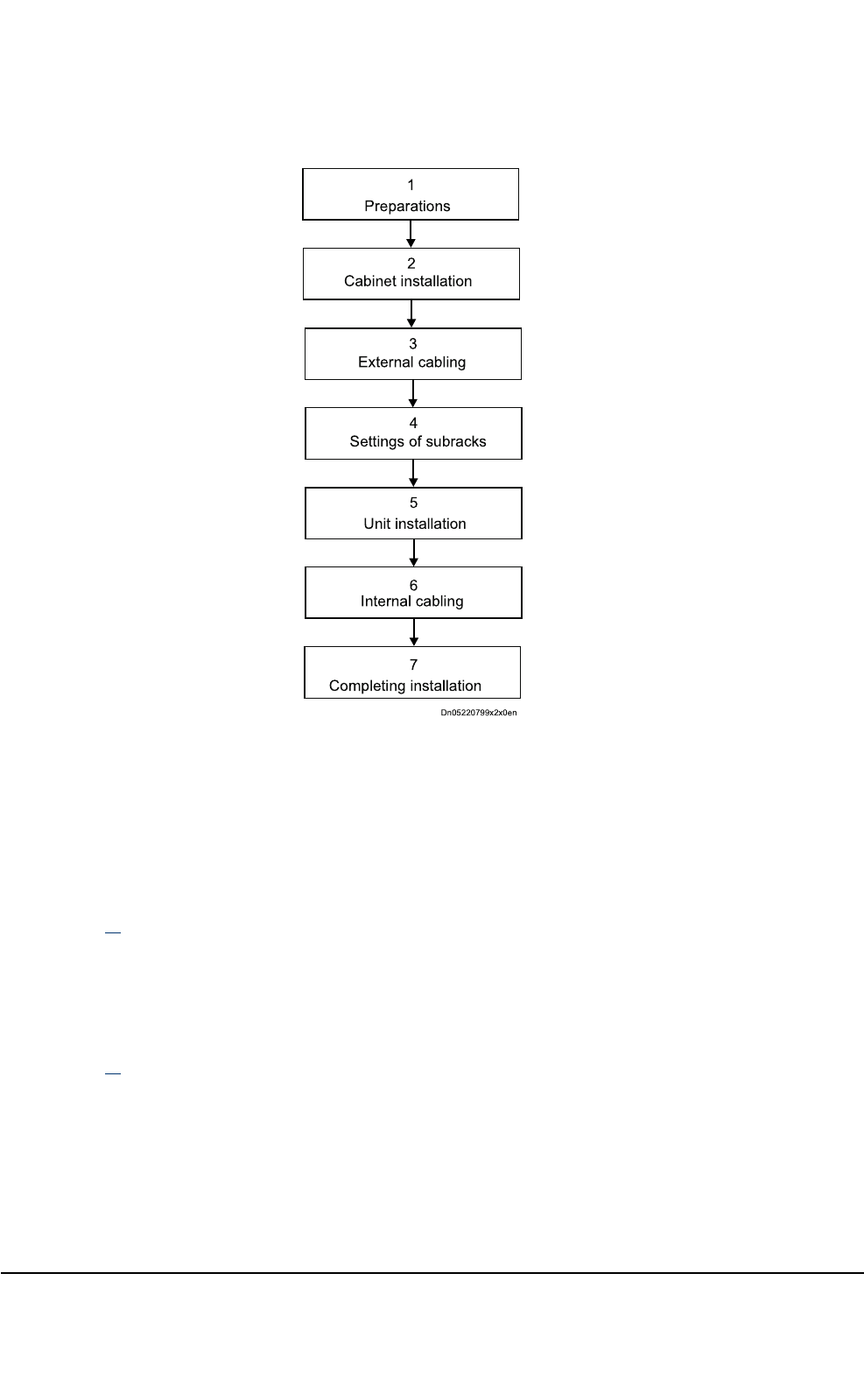
3.3.3Assessmentofcomplianceboundary
Thecomplianceboundaryisdenedastheareaaroundtheantenna,showninthefollowinggure.
Thecentreoftheantennaislocatedattheorigo.Distancesfromtheantennaareshown.
R
h
h
dn 04202552 x
2
x0xen
Figure3:Areaaroundtheantenna
ThecomplianceboundariesfortheTETRABaseStationsaregiveninthefollowingtablesfordifferent
powerlevelsattheantennainput.Theboundarieshavebeencalculatedusingdatafromatypicalomni
antennawith7.5dBigainforthe350-470MHzvariants,andwith12dBigainforthe806-869
MHzvariant.Alsothetypicalandworstcasepowerlevelcongurationsforgeneralpublic(GP)and
occupational(O)exposurelimitsareincludedinthefollowingtables.
Table2:Dimensionsofcomplianceboundaryinmeters(TB3350,TB3380,TB3410,TB3450)
Poweratantenna
input(W)
TB3350,TB3380,TB3410,
TB3450
R(m)h(m)
GPOGPO
202.10.91.91.7
403.01.32.11.8
603.71.62.21.8
804.21.92.41.9
1004.72.12.51.9
1205.22.32.52.0
DN04153465-08-3enTETRASystemRelease5.5–6.5-InstallingtheTB3
22(154)ThisdocumentisthepropertyofCassidianandshouldnotbecopiedorcirculatedwithoutpermission.

Table2:Dimensionsofcomplianceboundaryinmeters(TB3350,TB3380,TB3410,TB3
450)(cont’d.)
Poweratantenna
input(W)
TB3350,TB3380,TB3410,
TB3450
R(m)h(m)
GPOGPO
1405.62.52.62.0
1606.02.72.72.0
Table3:Dimensionsofcomplianceboundaryinmeters(TB3800)accordingtoEuropean,
FCCandICstandards
Poweratantenna
input(W)
TB3800
Europeanstandards
TB3800
FCC1.1310andICRSS-102
R(m)h(m)R(m)h(m)
GPOGPOGPOGPO
202.41.12.42.32.10.92.32.3
403.41.52.42.33.01.32.42.3
604.21.92.52.33.71.62.52.3
804.92.22.52.44.21.92.52.3
1005.42.42.62.44.72.12.52.3
1206.02.72.62.45.22.32.62.4
1406.42.92.62.45.62.52.62.4
1606.93.12.72.46.02.72.62.4
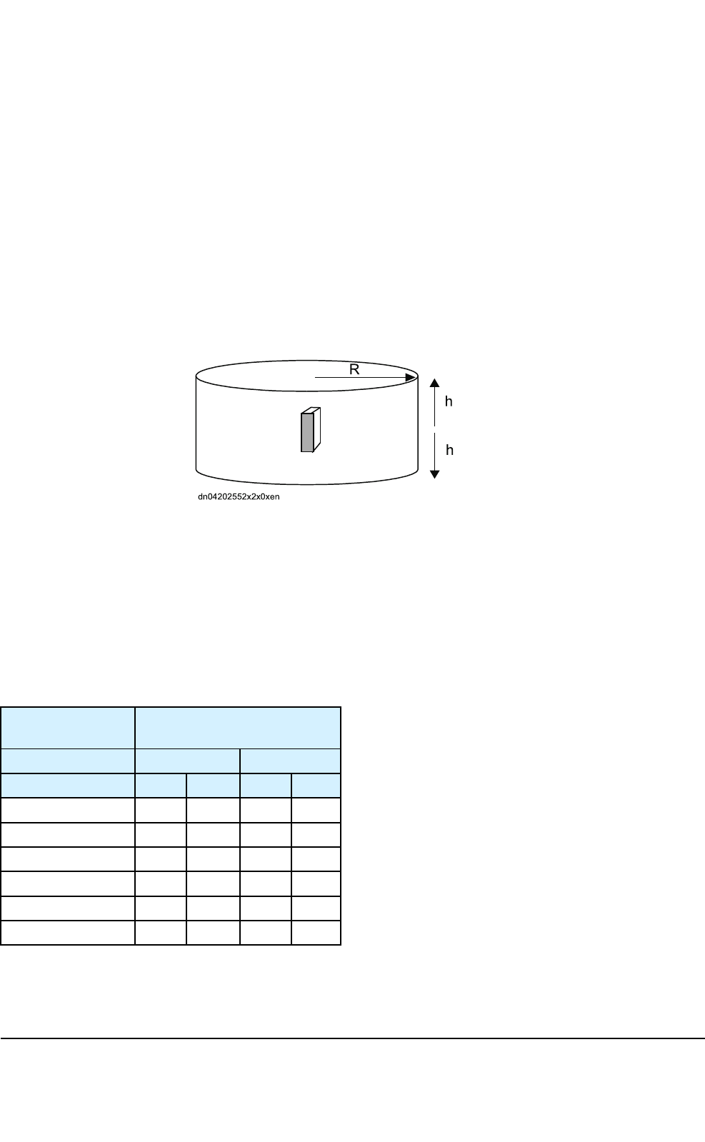
3.3.4Typicalconguration
Theantennaisconnectedthroughaconnectorandcable(s)tothebasestationasshowninthe
followinggure.Adetaileddescriptionofthecomponentsisgiveninthetablesbelow.
TETRASystemRelease5.5–6.5-InstallingtheTB3DN04153465-08-3en
ThisdocumentisthepropertyofCassidianandshouldnotbecopiedorcirculatedwithoutpermission.23(154)
Antenna connector
Cable
To the base station
dn04202564x1x0xen
Antenna
Figure4:Antennaconnectiontothebasestation
Table4:Detaileddescriptionofthecomponents
ComponentTypical
case
Worst
case
Power(Pout)25W25W
Totalconnectorloss0.0dB0.0dB
Totalcableloss1.0dB1.0dB
TotalLoss(L)=Totalconnectorloss+Totalcable
loss
1.0dB1.0dB
Numberoftransmitterunits(N)28
Poweratantennainput=40W160W
Table5:Typicalantennaspecication(TB3350,TB3380,TB3410,TB3450)
Frequency350–470MHz
Gain7.5dBi
PatternOmni
Electricaldowntilt0deg
Height/width/depth3000/100/100mm
DN04153465-08-3enTETRASystemRelease5.5–6.5-InstallingtheTB3
24(154)ThisdocumentisthepropertyofCassidianandshouldnotbecopiedorcirculatedwithoutpermission.
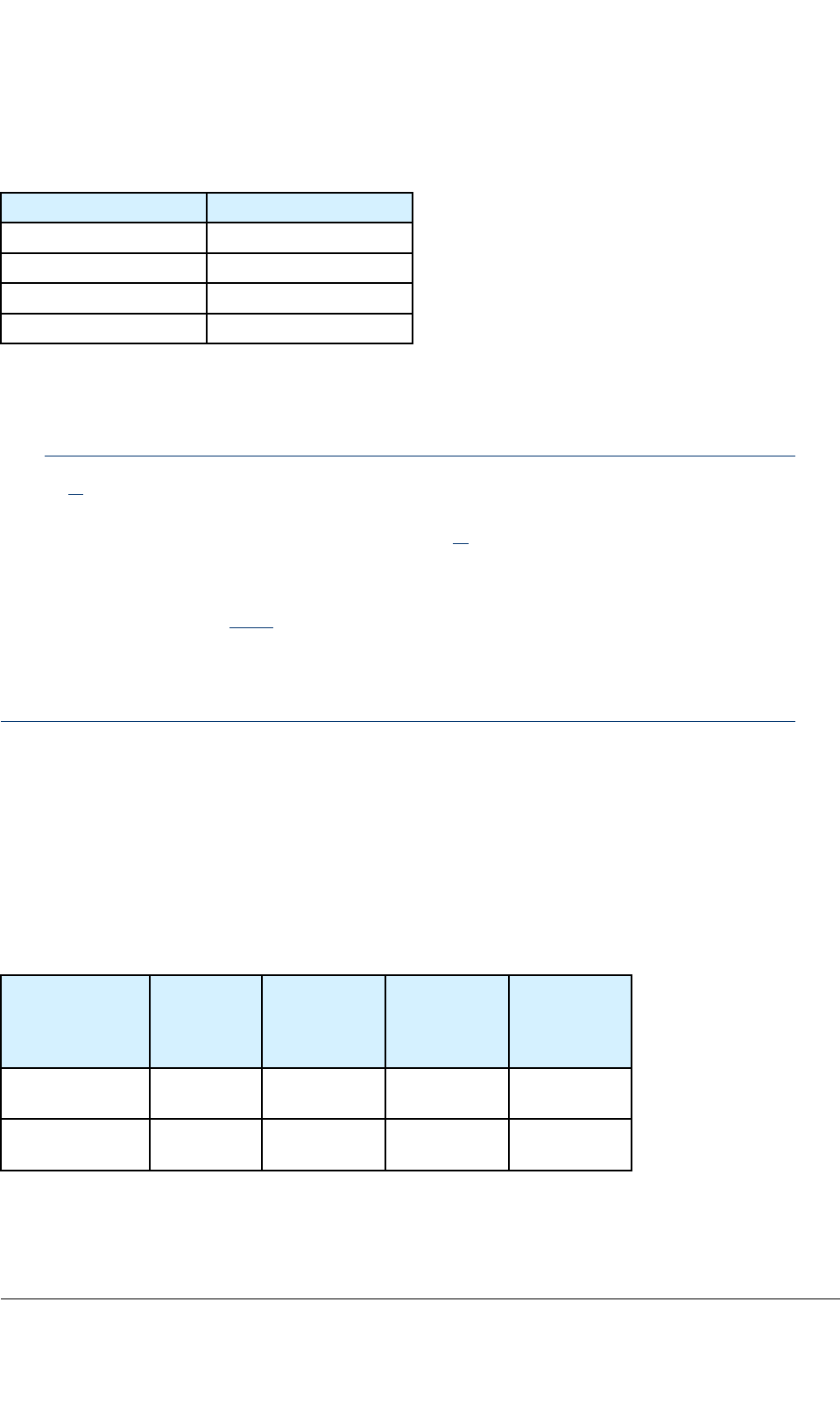
Table6:Typicalantennaspecication(TB3800)
Frequency806–869MHz
Gain12dBi
PatternOmni
Electricaldowntilt0deg
Height/width/depth4400/80/80mm
3.3.5Whenusingdifferentcongurations
Note
InTable2,thecomplianceboundariesaregivenfordifferentpowerlevels,includingthetypical
andworstcaselevels.Ifanexposurelimit,antenna,and/orcongurationareusedwhichdoes
notcorrespondtothelevelsorfrequenciesgiveninT able2,thecomplianceboundarymustbe
re-calculatedaccordingtoEN50383.
Theformulaforcalculatingthecomplianceboundaryusingthefar-eldmodel,whichisreferencedin
EN50383,isgiveninSection3.3.8.Thismodelisapplicableforcalculatingthecomplianceboundary
forthefar-eldregionandoverestimatesthecomplianceboundaryfortheradiatingnear-eldregion,
butisnotapplicableforcalculatingthecomplianceboundaryforthereactivenear-eldregionwhere
thedistancefromtheantennaislessthanorequaltoλ/4.
3.3.6AnnexA
CouncilRecommendation1999/519/ECforoccupationalandgeneralpublicelectromagneticexposure
limits.
Basicrestrictionsaregiveninthefollowingtable.
Table7:Basicrestrictions
Exposure
characteristics
Frequency
range
Wholebody
average
SARWkg-1
Localized
SAR(head
andtrunk)W
kg-1
Localized
SAR(limbs)
Wkg-1
Occupational
exposure
10MHz–10
GHz
0.41020
Generalpublic
exposure
10MHz–10
GHz
0.0824
TETRASystemRelease5.5–6.5-InstallingtheTB3DN04153465-08-3en
ThisdocumentisthepropertyofCassidianandshouldnotbecopiedorcirculatedwithoutpermission.25(154)

Note
AllSARvaluesaretobeaveragedoveranyperiodof6minutes.
Note
LocalizedSARaveragingmassisany10gofcontiguoustissue:themaximumSARsoobtainedshould
bethevalueusedfortheestimationofexposure.
Note
Basicrestrictionsbetween10GHzand300GHzaregiveninpowerdensities.
Foroccupationalexposureitis50Wm-2andforgeneralpublicexposureitis10Wm-2.
Referencevaluesarecalculatedfrombasicrestrictions.Theresultsaregiveninthefollowingtable.
Table8:Referencevaluescalculatedfrombasicrestrictions
Exposure
characteristics
FrequencyrangeElectriceld
strengthV/m
Equivalent
planewave
powerdensity
S(Wm-2)
Occupational
exposure
10—400MHz
400—2000MHz
2—300GHz
61
3f1/2
137
10
f/40
50
Generalpublic
exposure
10—400MHz
400—2000MHz
2—300GHz
28
1.375f1/2
61
2
f/200
10
Note
fstandsforfrequencyinMHz.
Note
Forfrequenciesbetween100kHzand10GHz,Sistobeaveragedoveranyperiodof6minutes.
Note
Forfrequenciesexceeding10GHz,Sistobeaveragedoveranyperiodof68/f1.05minutes(finGHz).
DN04153465-08-3enTETRASystemRelease5.5–6.5-InstallingtheTB3
26(154)ThisdocumentisthepropertyofCassidianandshouldnotbecopiedorcirculatedwithoutpermission.
3.3.7AnnexB:FCC1.1310andIndustryCanadaRSS-102
Radiofrequencyradiationexposurelimits
RFeldstrengthlimitsforpowerdensityaregiveninthefollowingtable.
Table9:RFeldstrenghtlimitsforpowerdensity
Exposure
characteristics
Frequencyrange
(MHz)
Power
density
(W/m2)
Averagingtime
(minutes)
Occupational/
Controlled
environment
300–1500f/306
Generalpublic/
Uncontrolled
environment
300–1500f/150FCC1.1310:30
RSS-102:6
Note
fstandsforfrequencyinMHz.
3.3.8AnnexC:Far-eldcalculationmethod
Thismodelisapplicableforcalculatingthecomplianceboundaryforthefar-eldregionandover
estimatesthecomplianceboundaryfortheradiatingnear-eldregion,butisnotapplicableforthe
calculatingthecomplianceboundaryforthereactivenear-eldregionwherethedistancefromthe
antennaislessthanorequaltoλ/4.Thereforeallthecalculationsarevalidwhenthecompliance
boundaryisgreaterorequaltotheantennadimensionsplusλ/4.
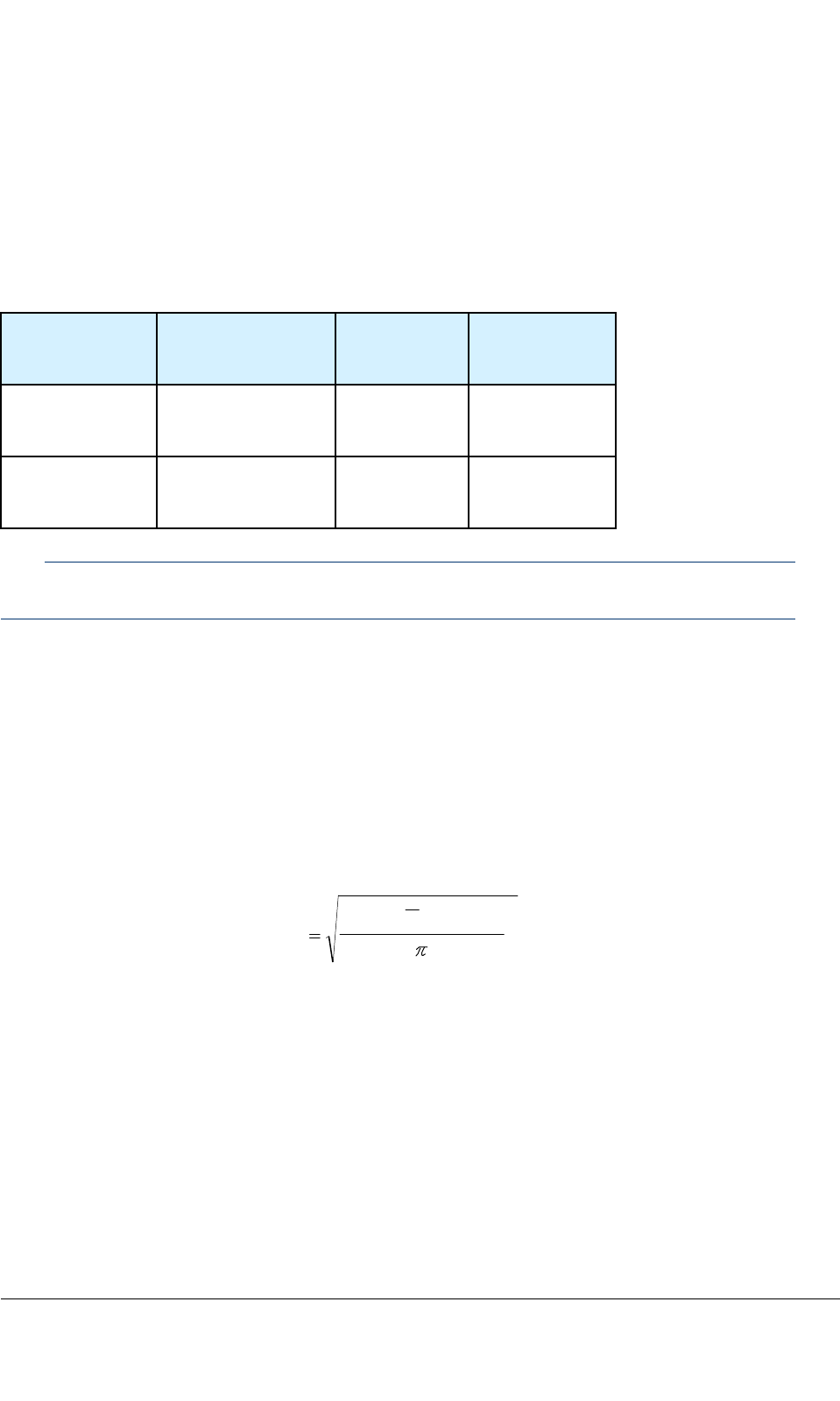
Thecomplianceboundaryinmetres,orrmin,iscalculatedaccordingtothefollowingequation:
S
P
LG
N
r
4
10/)(
10
out
min
Figure5:Formulaforcalculatingcomplianceboundaries
Theformulaincludesthefollowingfactors:
•N-numberoftransmitterunitsperoneantenna
•G-antennagain(dBi)
•L-minimumcableloss(dB)
•Pout-maximumpowerofonetransmitterunit(W)
TETRASystemRelease5.5–6.5-InstallingtheTB3DN04153465-08-3en
ThisdocumentisthepropertyofCassidianandshouldnotbecopiedorcirculatedwithoutpermission.27(154)

•S-powerdensitylimit(W/m2)
Inthefar-eld,theeldcalculationdoesnottakeintoaccounttheantennasize,whichisassumedtobe
apointsource.Thereforewhencalculatingthecomplianceboundary,thefar-elddata,antennasize,
andreactiveeldcriteriahavetobetakenintoaccount.
3.4Weightandtemperature
3.4.1Cabinet
Caremustbetakenwhenhandlingthecabinets.Installcabinetliftingeyeletsanduseamechanical
liftingequipmenttoliftacabinet.
3.4.2Plug-inunits
Caremustbetakenwhenhandlingheavyplug-inunits.Theseareequippedwithwarninglabels.
WARNING
Donotcarryheavyunitsfromthehandle.Thehandleisonlyforpullingtheunitoutoftherack.
3.4.3Hightemperatures
Caremustbetakenwhentouchingunitsastheymayreachhightemperatures.
3.5Cautions
3.5.1Electromagneticelds
Wheninstallingtheantennas,theemissionofotherantennasnearbyhastobeknownbeforehand.
3.5.2Antennaconnectors
DonotdisconnecttheantennaconnectorswhentheTB3ispoweredon.
DN04153465-08-3enTETRASystemRelease5.5–6.5-InstallingtheTB3
28(154)ThisdocumentisthepropertyofCassidianandshouldnotbecopiedorcirculatedwithoutpermission.

3.5.3Storageandtransportation
Duringstorageandtransportation,theunitsmustremainintheiroriginalpackagesinorderto:
•avoidmechanicaldamage
•maintaintraceability
•protecttheunitsagainststaticelectricity.
3.5.4Electrostaticdischargeprotection
Anelectrostaticsensitivedeviceisanelectroniccomponentthatmaybepermanentlydamagedby
electrostaticchargesencounteredinroutinehandling,testing,andtransportation.
Electrostaticsensitivedevicesarelabelledasfollows:
Figure6:Signforelectrostaticsensitivedevices
Electrostaticdischargeiscausedbydirectcontactoranelectrostaticeld.Ifachargedbody
approachesanelectricallyconductingsurface,theacquiredpotentialisdischarged.Anequalizing
currentcanthenowintheassociatedcircuitryandgeneratepermanentlydamagingvoltagesby
induction.
CAUTION
Alwayswearaclose-ttingearthinghandstraparoundyouruncoveredwristwhenhandling
electrosensitiveTB3units.
Thehumanbodyshouldbeearthedatthesamepotentialasthecomponentorequipmentbeing
handled.Thehandstrapcreatesanequipotentelectricalconnectionbetweentheobjectandthe
human.ThereisanearthstudinallTB3cabinetstowhichthehandstrapmustbeconnected.
3.5.5Securityininstallationandmaintenance
Theinstructionsinreferencesmustbefollowedwheninstallingthisequipment.Itmaybedangerousto
theinstallationpersonneltoneglecttheinstructions.
TETRASystemRelease5.5–6.5-InstallingtheTB3DN04153465-08-3en
ThisdocumentisthepropertyofCassidianandshouldnotbecopiedorcirculatedwithoutpermission.29(154)

Theinstructionsinreferencesmustbefollowedwhenperforminganymaintenancemeasuresonthis
equipment.Neglectingtheinstructionsmaybedangeroustomaintenancepersonnel.
3.6Sitepreparations
Thecabinetinstallationphaserequiresthatthesiteisproperlysurveyedandprepared,andallrequired
externalservicescorrectlyinstalled.Thesitesurveymustidentifyanyspecialrequirementsforthe
installation,suchasliftingequipment.
Topreparethesiteforthecabinetinstallation
1)Checktheaccessibilitytothecabinet.
2)Inspectthesitevisuallyandmakesurethefollowingrequirementsarefullled:
•Thesite-specicinstallationinstructionsareavailable.
•Thesiteispreparedaccordingtotheinstructions.
•Thesitesurveyiscompleted.
•Thesitesurveyreportisavailable.
•Thesiteisclean.
3)Verifythatallexternalconnectionsforthecabinetareavailable:
•earthingpoint
•mainspowerwithcorrectratingandcomplyingwithnationalrequirements(ACorDC
poweraccordingtothesite)
•transmissioninterfacetotheexchange
•TXandRXantennacables
•cablefromGlobalPositioningSystem(GPS)antennaunit(optional)
•customeralarmcable(optional).
4)Ensurethecabinetcanbeinstalledsafelybyverifyingthefollowing:
•Theliftingandotherequipmentisavailable.
•Thereisadequateworkingspace.
5)Checkthatthedeliveryiscomplete.
3.7Tools
Theinstallationpersonnelmustbefamiliarwiththetoolslistedinthefollowingtableandcompetentin
usingthem.
DN04153465-08-3enTETRASystemRelease5.5–6.5-InstallingtheTB3
30(154)ThisdocumentisthepropertyofCassidianandshouldnotbecopiedorcirculatedwithoutpermission.

Table10:Installationtools
ToolQuantity
Rollrule,3m1
Rollrule,20m1
Calliperrule1
Spiritlevel,>1m1
Feltpen,1mm2
Maskingtape,25mm1
Screwdriverset(forslotted5andcrossrecessPZ1,PZ2)and
TorxT10,T20,T30
1
SetofAllenkeys(long)1
TorxT850mmLongPowerBit1
Open-endorboxwrenches8,10,16,and171
Ratchethandle,extensionshaft,andsocket19mm1
TorquewrenchforSMA,Nand7/16connectors1
Side-cuttingpliers1
Combinedpliers1
Pointedpliers1
Strippingpliersfor2.5and4mm2wires1
Plasticmallet1
Knife1
Scissors1
CablepliersmaxCu50mm21
Strippingknife1
CrimpingtoolforconnectorsC16+16,C25+25andC50
+50
1
Multimeter(tolerance0.1%)1
(Solderingironandtin1)
CrimperforBNCandSMBconnectors1
(Hammerdrill,15mmbit1)
Thetoolsinparenthesesarenotabsolutelynecessaryforasuccessfulinstallation,butmaybeneeded
insomecases.
TETRASystemRelease5.5–6.5-InstallingtheTB3DN04153465-08-3en
ThisdocumentisthepropertyofCassidianandshouldnotbecopiedorcirculatedwithoutpermission.31(154)

3.8Traceability
Unitsarelabelledwithpermanentlyattachedproductidenticationlabels.Thelabelsaredesigned
tobepermanentthroughoutthelifespanoftheTB3.Makesurethattheproductidenticationlabels
areintheirplacesandundamaged.
DN04153465-08-3enTETRASystemRelease5.5–6.5-InstallingtheTB3
32(154)ThisdocumentisthepropertyofCassidianandshouldnotbecopiedorcirculatedwithoutpermission.
CHAPTER
4
Cabinetinstallation
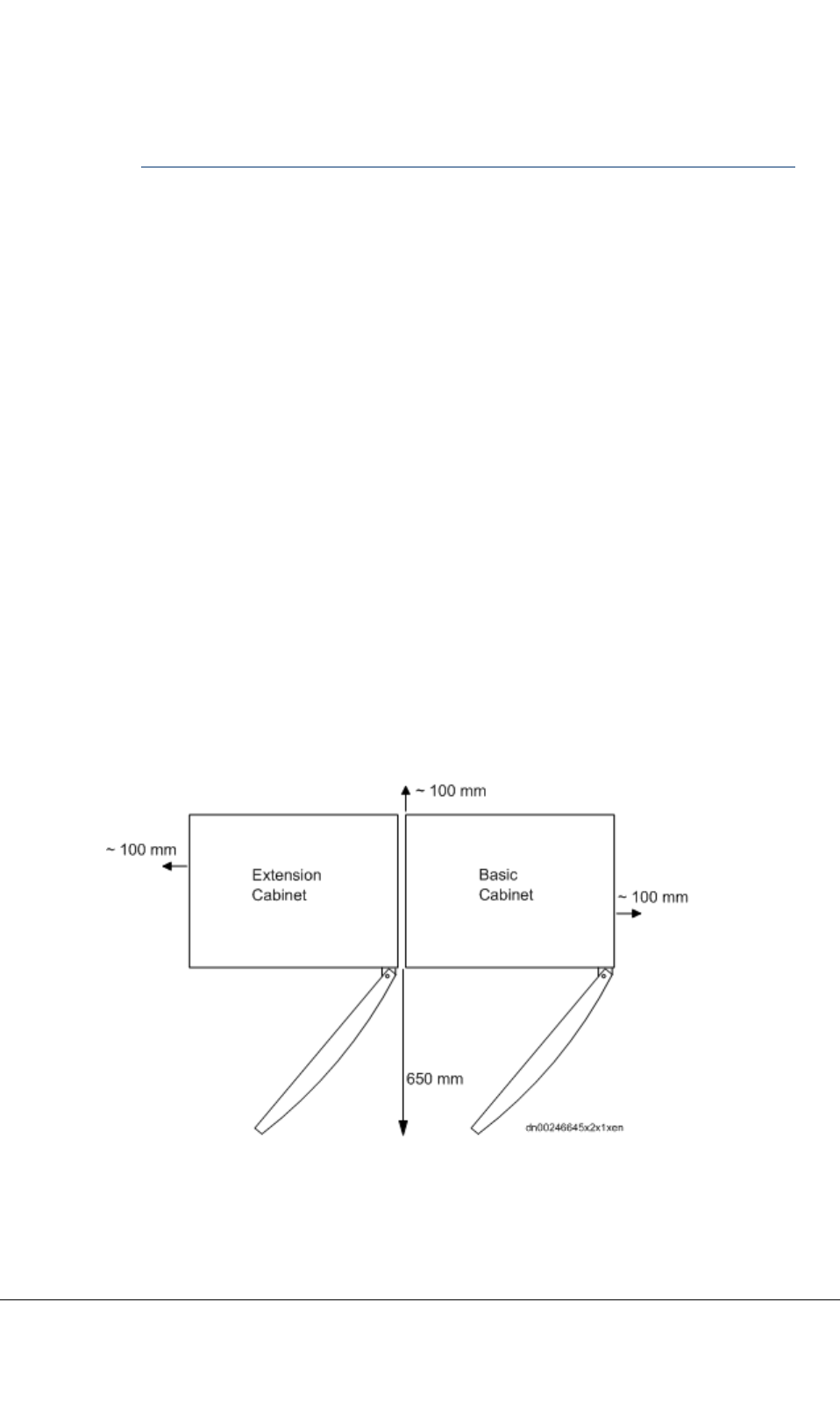
4.1Spacerequirements
Toensurethattheequipmentgetsenoughcoolingair,observethefollowingminimumclearances
aroundthecabinets:
•100mmbetweenthecabinetsidepanels,backpanelandthewall
•300mmabovethecabinettop
•650mmatthecabinetfront.
Aminimumclearanceof35mmmustbeleftbetweenthebaseandthecabinetbottomtoensure
adequateairow.
Figure7:Cabinetsideandrearclearances
TETRASystemRelease5.5–6.5-InstallingtheTB3DN04153465-08-3en
ThisdocumentisthepropertyofCassidianandshouldnotbecopiedorcirculatedwithoutpermission.33(154)

ThedimensionsoftheTB3cabinetare:
•width600mm(withextensioncabinet1220mm)
•height1615mm(includesthe35mmclearancebeneaththecabinetbottom)
•depth530mm.
Theextensioncabinetcanbeplacedoneithersideofthebasiccabinet,andthecabinetfrontdoorcan
beinstalledtoopeneithertotheleftortotheright.
4.2Unpackingandchecking
CAUTION
Heavyweight.Becarefulwhenliftingthecabinet!Thecabinetisdeliveredwiththeinternalcables,
theroofframe,andthedoorinplace.
Eyebolts(M12)canbeusedforlifting.
Tounpackandcheckthecabinet
1)Openthetransportationcontainer.
2)Carefullyliftoffthecontaineraroundthecabinet.
3)Carefullyliftthecabinetintoanuprightpositionusingthecontainerbottom.
4)RemovethepolystyreneL-shieldsandtheplasticpacking.
5)Openthecabinetdoorandremovethethreesilicagelbagsthathavebeenputintothecabinet
toremovemoisture.
6)Checkthedeliveryagainstthepackinglist.
7)AddthepackinglistintheSiteFolder.
8)T akethetypeplatestickerfromtheplasticbaglocatedinthedummyplatesetboxandattachit
onthecabinetaccordingtothefollowinggure.
DN04153465-08-3enTETRASystemRelease5.5–6.5-InstallingtheTB3
34(154)ThisdocumentisthepropertyofCassidianandshouldnotbecopiedorcirculatedwithoutpermission.
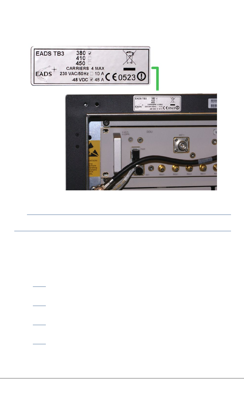
Figure8:Placementofthetypeplatesticker
Note
TheSMAterminalsintheplasticbagareforterminatingtheunusedoutputsinDRMCsandDDUs.
4.3Installationpreparations
Thischapterprovidesinstructionsforremovingthecabinetroofframe,removingthefrontdoor,
changingtheopeningdirectionofthedoor,andremovingthebackpanel:
•Section4.3.1.
Removetheroofframeifyouuseliftingeyeboltsforlifting.
•Section4.3.2.
Removingthefrontdoorisoptional.
•Section4.3.3.
Changingtheopeningdirectionofthedoorisoptional.
•Section4.3.4.
TETRASystemRelease5.5–6.5-InstallingtheTB3DN04153465-08-3en
ThisdocumentisthepropertyofCassidianandshouldnotbecopiedorcirculatedwithoutpermission.35(154)

Removingthebackpanelisnecessaryonlyifyouboltthecabinettothebasethroughtherear
boltingholes.Thefrontandmiddleboltingholesareaccessiblethroughthefrontdoor.
Note
Openingthedoororremovingthebackpanelwillcauseanalarmintheexchange.
4.3.1Removingtheroofframe
Toremovetheroofframe
1)Loosen,butdonotcompletelyremove,thefourroofframexingscrews.
2)Workingfromthebackofthecabinet,pulltheroofframetowardyouandliftitoff.
Rettheroofframebyreversingthestepsabove.
4.3.2Removingthedoor
Removingthefrontdoorisnotnecessarybutitispossible.
CAUTION
Heavyweight.Becarefulwhenliftingthedoor.
Toremovethecabinetfrontdoor
1)Openthedoortoa90degreeangle.
2)Removethegroundcablefromthedoorxingpoint.
3)LoosentheM5screwsofthelowerhinge(cabinetside)withan8mmwrench.
4)Liftthedoorofftheupperhinge.
5)Lowerthedooroffthelowerhinge.
Retthedoorbyreversingthestepsabove.
4.3.3Changingtheopeningdirectionofthedoor
Thecabinetdoorcanbeinstalledtobeopenedeitherfromtherightortheleft.Followtheinstructions
belowforchangingtheopeningdirection.
Tochangetheopeningdirectionofthedoor
1)Openthedoortoa90degreeangle.
DN04153465-08-3enTETRASystemRelease5.5–6.5-InstallingtheTB3
36(154)ThisdocumentisthepropertyofCassidianandshouldnotbecopiedorcirculatedwithoutpermission.

2)Removethegroundcablefromthedoorxingpoint.
3)LoosentheM5screwsofthelowerhinge(cabinetside)withan8mmwrench.
4)Liftthedoorofftheupperhinge.
5)Lowerthedooroffthelowerhingeandlayittooneside.
6)Removethelowerhinge.
7)Installthelowerhingeastheupperhingeontheotherside.
8)Removetheupperhinge.
9)Installtheupperhingeasthelowerhingeontheotherside.
Note
Leavethelowerhingeintheupperpositionanddonottightenthescrewsyet.
10)Liftthedoorontheupperhinge.
11)Slidethelowerhingeintothelowerpositionandtightenallscrews.
12)Re-attachthegroundcabletothedoorxing.
4.3.4Removingthebackpanel
Youwillneedtoremovethebackpanel,ifyouboltthecabinettothebasefromtherearofthecabinet.
CAUTION
Heavyweight.Becarefulwhenliftingthecabinetbackpanel.
ThebackpanelisattachedtothecabinetwitheightTorxscrews.
Toremovethebackpanel
1)FirstremovetheroofframeasinstructedinSection4.3.1.
2)Startingfromthebottom,loosenalltheTorxscrewsusingtheT orxkey.
3)Liftthepanelandpullitawayfromthecabinet.
Reinstallthebackpanelbyreversingthestepsabove.
4.4Liftingthecabinet
CAUTION
Liftthecabinetwithouttheunitsinstalled.
TETRASystemRelease5.5–6.5-InstallingtheTB3DN04153465-08-3en
ThisdocumentisthepropertyofCassidianandshouldnotbecopiedorcirculatedwithoutpermission.37(154)

Whenusingamechanicalliftingdevice,useallfourM12liftingeyeboltsforlifting.
Liftthecabinettoitsplacebycraneorsomeothermechanicalliftingmethod.
Toliftthecabinet
1)Removethecabinetroofframe.
2)FastenallfourM12liftingboltstothecabinettop.
3)Attachtheliftingropestotheliftingeyebolts.
4)Liftthecabinetdirectlyupward.
5)Positionthecabinettothecorrectlocation.
6)Removetheliftingropes.
Theliftingeyeboltscanbeleftinplaceorremovedforreuse.
4.5Mountingthecabinet
Althoughthecabinetcanbeleftstandingonitsfeet,boltingittothebaseisrecommended.The
maximumboltsizeisM12.Theboltsareincludedinthedelivery.
Notethefollowingcaution:
CAUTION
Ifthereistheslightestdangerofthecabinettopplingover,asinearthquakeareas,thecabinetmust
beboltedtothebase.Thecabinethassixboltingpointsatthecabinetbottomforanchorbolts.The
frontandmiddleboltingpointsareaccessiblethroughthefrontdoor.Foraccesstothefrontbolting
points,theairdeectormustberemoved.Foraccesstothemidboltingpoints,thefanunitcover
plateandthefanunitsmustberemoved.Foraccesstotherearboltingpoints,thecabinetback
panelmustberemoved.
DN04153465-08-3enTETRASystemRelease5.5–6.5-InstallingtheTB3
38(154)ThisdocumentisthepropertyofCassidianandshouldnotbecopiedorcirculatedwithoutpermission.
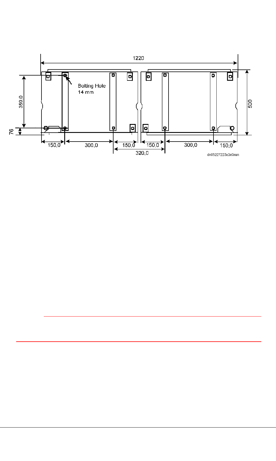
Figure9:BasicandExtensioncabinetboltingpoints
Aminimumclearanceof35mmmustbeleftbetweenthebaseandthecabinetbottomtoensure
adequateairow.
Tomountthecabinettothebase
1)Ifnecessary,removethecabinetdoor,fanunitcoverplate,fanunit,airdeector,andtheback
panel.
2)Useaspiritleveltoverifythatthecabinetishorizontal.Ifthecabinetisnothorizontal,adjust
thecabinet’sfeetuntilitis.
Toboltthecabinettothebase
1)Insertatleastfouranchorboltsinthebase.
2)Insertnutsandwasherstotheboltsandadjusttheirheightsothattheyarehorizontalandonthe
samelevelfromthebaseasthecabinet’sfeet.Checkwithaspiritlevel.
CAUTION
Ifyouboltthecabinettothebase,makesurethecabinetrestsbothontheboltsandthecabinet’s
feetsothatthecabinetbottomishorizontal.Unevenboltingmaydamagethecabinet.
3)Liftthecabinetinplace.
4)Insertnutsandwasherstotheboltsonthecabinetbottomsideandtighten.
5)Adjustthecabinet’sfeetuntilthecabinetrestsonboththeboltsandonthefeet.
TETRASystemRelease5.5–6.5-InstallingtheTB3DN04153465-08-3en
ThisdocumentisthepropertyofCassidianandshouldnotbecopiedorcirculatedwithoutpermission.39(154)

4.6Installingthecombinerguidingsupports
Thecombinerguidingsupportscanbeinstalledinseveraldifferentcongurations.Theguresonthe
followingpagesillustratethedifferentpossiblecongurations.Themeaningsofthereferencenumbers
intheguresareexplainedinthetablebelow.
Table11:Themeaningsofthereferencenumbers
Ref.numberObjectname
2Dummyplate0.5U
3Dummyplate1.5U
4Dummyplate1U
52U-frontpanel
6Guidesupport
7TXscrewM6X12
10dummyplate3/4U
11Dummyplate2U
DN04153465-08-3enTETRASystemRelease5.5–6.5-InstallingtheTB3
40(154)ThisdocumentisthepropertyofCassidianandshouldnotbecopiedorcirculatedwithoutpermission.
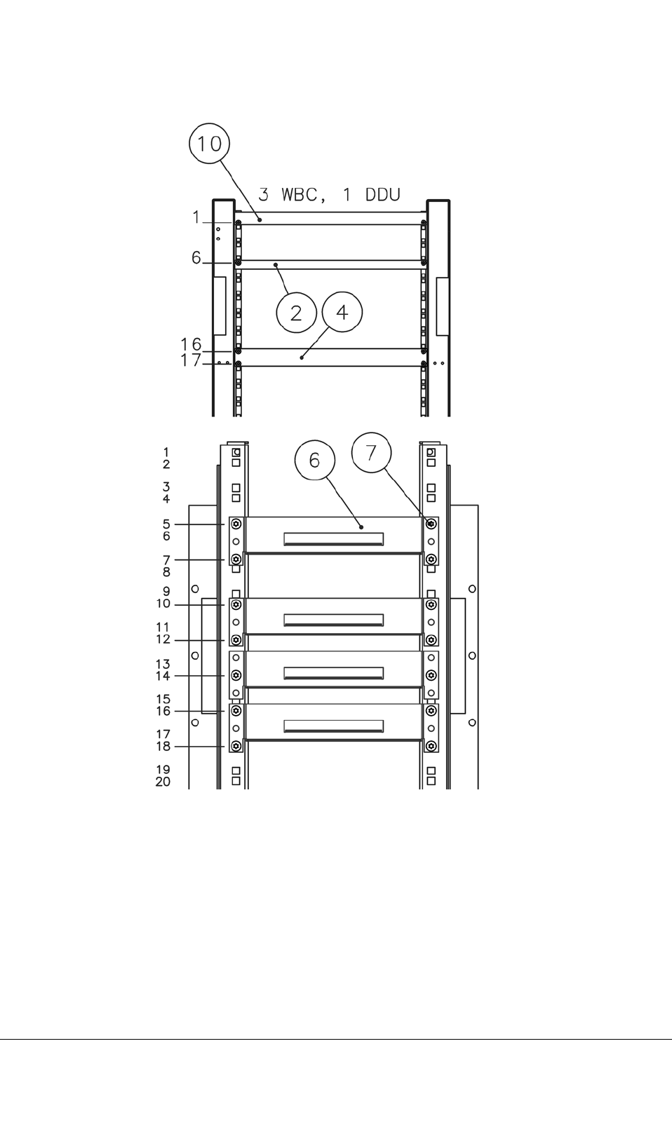
Figure10:Dummyplatesettingsandcombinerguidingsupportswith3WBCsand1DDU
TETRASystemRelease5.5–6.5-InstallingtheTB3DN04153465-08-3en
ThisdocumentisthepropertyofCassidianandshouldnotbecopiedorcirculatedwithoutpermission.41(154)
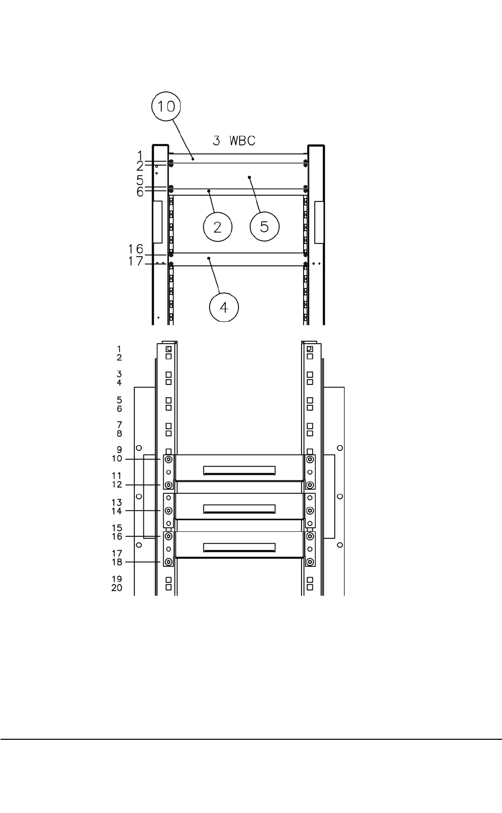
Figure11:Dummyplatesettingsandcombinerguidingsupportswith3WBCs
DN04153465-08-3enTETRASystemRelease5.5–6.5-InstallingtheTB3
42(154)ThisdocumentisthepropertyofCassidianandshouldnotbecopiedorcirculatedwithoutpermission.
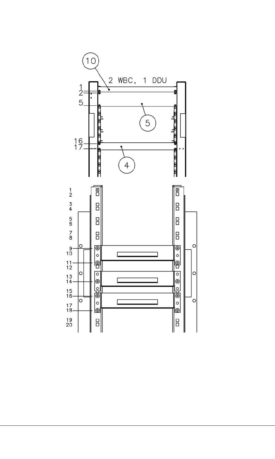
Figure12:Dummyplatesettingsandcombinerguidingsupportswith2WBCsand1DDU
TETRASystemRelease5.5–6.5-InstallingtheTB3DN04153465-08-3en
ThisdocumentisthepropertyofCassidianandshouldnotbecopiedorcirculatedwithoutpermission.43(154)
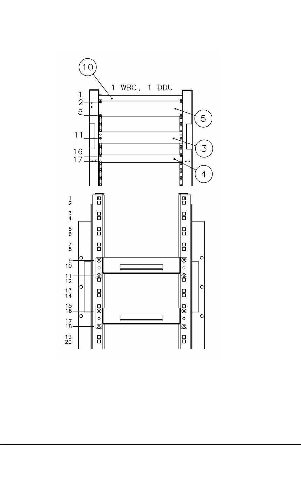
Figure13:Dummyplatesettingsandcombinerguidingsupportswith1WBCand1DDU
DN04153465-08-3enTETRASystemRelease5.5–6.5-InstallingtheTB3
44(154)ThisdocumentisthepropertyofCassidianandshouldnotbecopiedorcirculatedwithoutpermission.
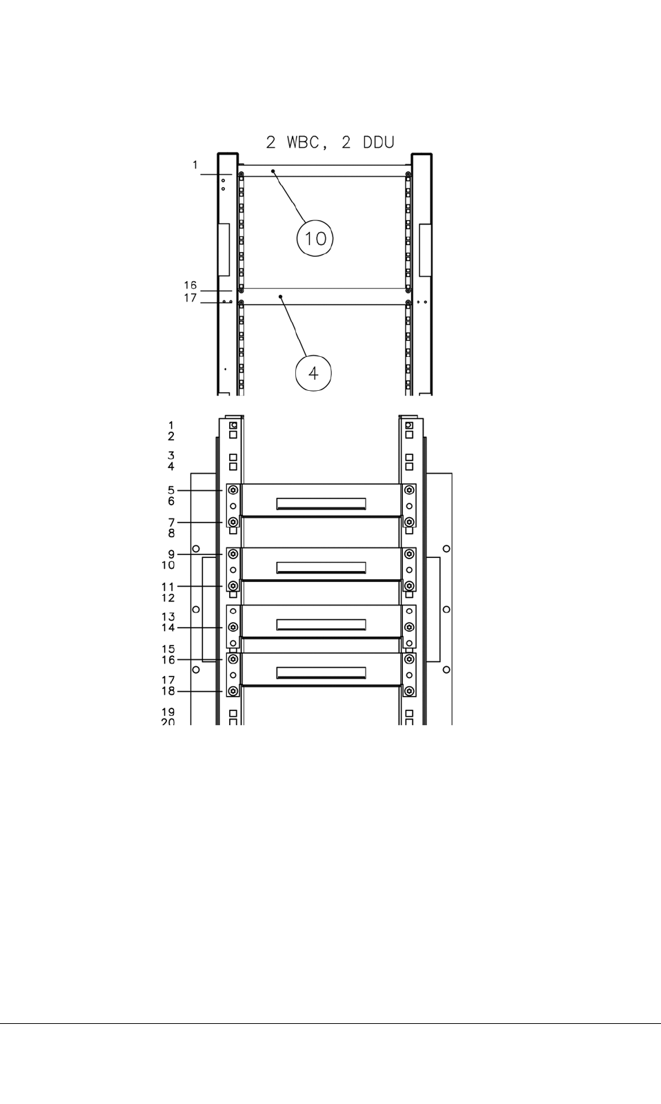
Figure14:Dummyplatesettingsandcombinerguidingsupportswith2WBCsand2DDUs
TETRASystemRelease5.5–6.5-InstallingtheTB3DN04153465-08-3en
ThisdocumentisthepropertyofCassidianandshouldnotbecopiedorcirculatedwithoutpermission.45(154)
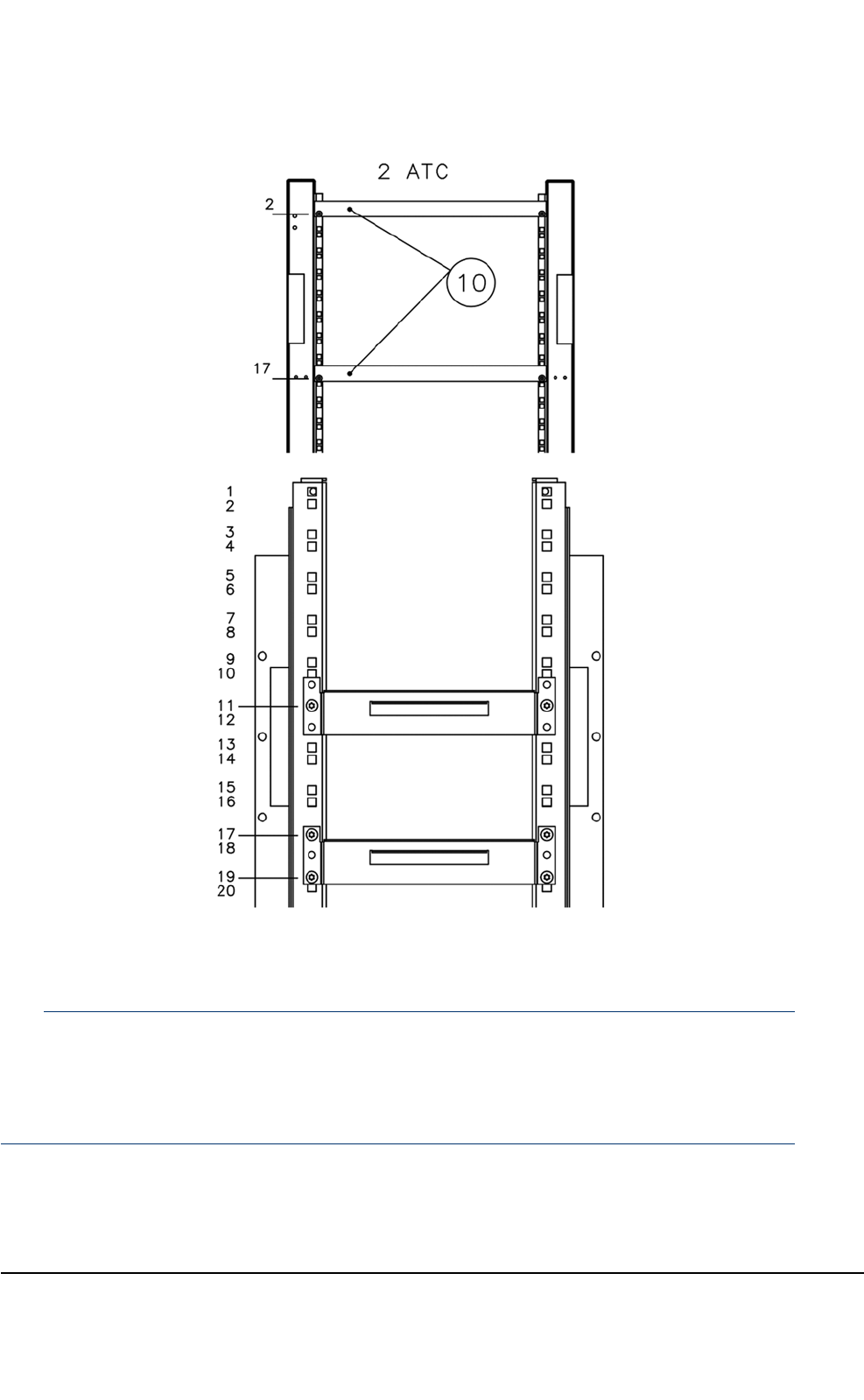
Figure15:Dummyplatesettingsandcombinerguidingsupportswith2ATCs
Note
Becausetheguidingsupport’sxingholesarelargerthanthediameterofthexingscrews,makesure
thatyoupushtheupperguidingsupportashighasitwillgobeforetighteningthescrews.Similarly,
pushthelowerguidingsupportaslowasitwillgo.Thiswayyouwillensurethatthereismaximum
spacebetweentheguidingsupports.
DN04153465-08-3enTETRASystemRelease5.5–6.5-InstallingtheTB3
46(154)ThisdocumentisthepropertyofCassidianandshouldnotbecopiedorcirculatedwithoutpermission.
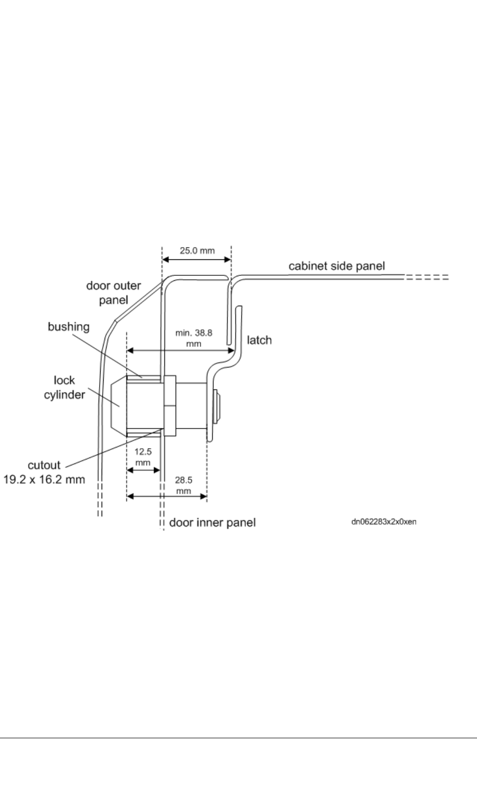
4.7Doorlockassembly
Alockcanbettedonthedoorofthecabinet,butitisnotpartofthedeliveryandmustbepurchased
separately.Inthefollowing,examplesofsuitablelockingdevicesaregiven:
•ASSAABLOYtype3277C(cylinder)+434852(cam)
•SOUTHCOtypeCM-2–3C101–2SB(cylinder)+CM-C210(cam).
Notethatthebushingrequiredinthelockinstallationisdeliveredwiththecabinet,inaplasticbag
attachedtotheinnerpanelofthecabinetdoor.
Thefollowinggureshowsthedimensionsofthelockassembly.
Figure16:Dimensionsofthelockassembly
4.8Installingtheextensioncabinet
Theextensioncabinetcanbeinstalledtoeithersideofthebasiccabinetsothatthecabinetsfacein
thesamedirectionandthereisa20mmgapbetweenthem.Adoublecabinetinstallationconsists
ofthefollowingprocedures:
•Preparingthecableopeningsonopposingsidesofthecabinets.
TETRASystemRelease5.5–6.5-InstallingtheTB3DN04153465-08-3en
ThisdocumentisthepropertyofCassidianandshouldnotbecopiedorcirculatedwithoutpermission.47(154)
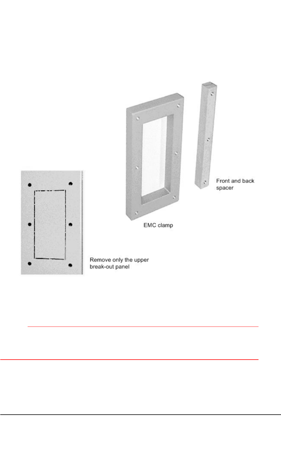
•JoiningthecabinetswiththeEMCclamproundthecableopeningandwithaspacer.
•Boltingthecabinetstothebasewhennecessary.
Figure17:Break-outpanel,EMCclamp,andspacers
4.8.1Cuttingoutthebreak-outpanel
CAUTION
Usesidecuttersforthisprocedure.Neveruseahacksaw:theresultingmetaldustandfragments
woulddamagetheequipment.Becarefulwhenpreparingthecableopenings.Thecutedgesof
theopeningmaycauseinjury.
DN04153465-08-3enTETRASystemRelease5.5–6.5-InstallingtheTB3
48(154)ThisdocumentisthepropertyofCassidianandshouldnotbecopiedorcirculatedwithoutpermission.

Tocutoutthebreak-outpanels
Note
Removeonlytheupperbreak-outpanelinbothcabinets.
1)Withsidecutters,cutalongtheperforatedlineatthetopofthebasiccabinetsideuntilthe
break-outpanelcanberemoved.
2)Repeatfortheopposingsideintheextensioncabinet.
3)Cleanawaypossiblemetaldustandfragments.
4)Paintthecutedgesofthecableopeningwithfast-dryingcorrectionpaint.Waituntilthepaintis
drybeforemountingtheEMCclamp.
4.8.2Joiningthecabinets
Tojointhecabinets
1)TheEMCclampandspacersarefastenedtooneofthecabinetswithM6andM5screwsand
washers.Seethefollowinggure.
2)Movethecabinetssidebysidesothecabinetfrontsareush.
3)TheothercabinetisfastenedtotheclampandspacerswithM6andM5screwsandwashers.
4)Boltthecabinetstothebasewhennecessary.
TETRASystemRelease5.5–6.5-InstallingtheTB3DN04153465-08-3en
ThisdocumentisthepropertyofCassidianandshouldnotbecopiedorcirculatedwithoutpermission.49(154)
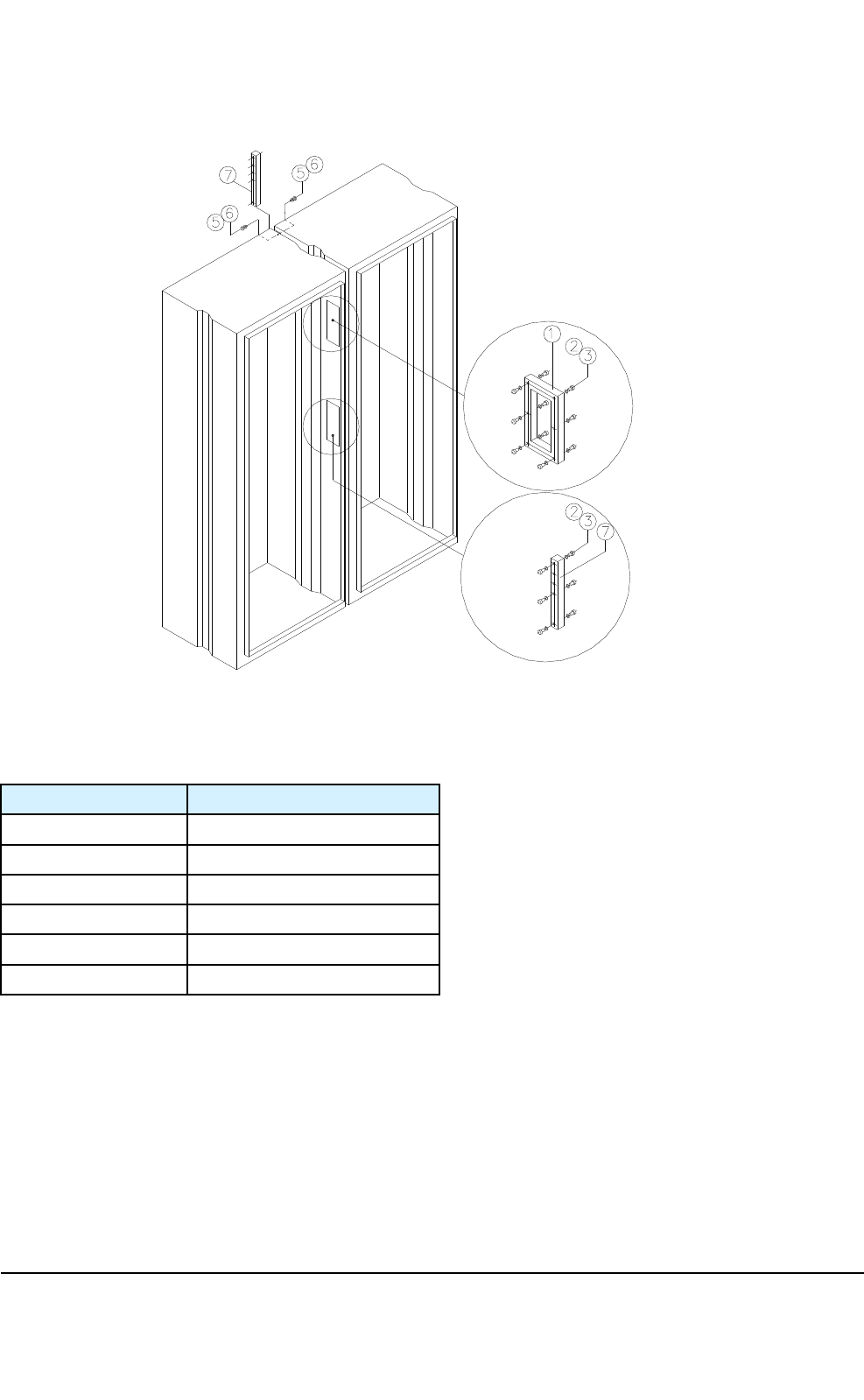
Figure18:Joiningthecabinets
Table12:Themeaningsofthereferencenumbers
Ref.numberObjectname
1EMCclamp
2M6screw
3B6washer
5M5screw
6B5washer
7spacer
4.9Dummyunitsandpanels
Tosecureproperventilation,theemptyTTRXunitlocationsmustbeequippedwiththedelivered
dummyunits.Alltheotheremptyplug-inunitlocationsmustbettedwithdummypanels.
DN04153465-08-3enTETRASystemRelease5.5–6.5-InstallingtheTB3
50(154)ThisdocumentisthepropertyofCassidianandshouldnotbecopiedorcirculatedwithoutpermission.

Note
Thedummyunitsanddummypanelsmustbeinstalledbeforethefrontcablingisdone.
TETRASystemRelease5.5–6.5-InstallingtheTB3DN04153465-08-3en
ThisdocumentisthepropertyofCassidianandshouldnotbecopiedorcirculatedwithoutpermission.51(154)

PAGEINTENTIONALLYLEFTBLANK
DN04153465-08-3enTETRASystemRelease5.5–6.5-InstallingtheTB3
52(154)ThisdocumentisthepropertyofCassidianandshouldnotbecopiedorcirculatedwithoutpermission.

CHAPTER
5
Externalcabling
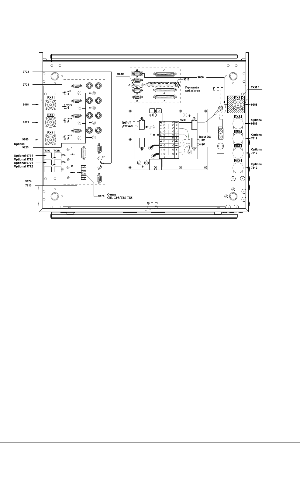
5.1Cabinettopinterfaces
ReadcarefullySection3.1ofthisdocumentbeforecommencinginstallationofcables.
Usethesite-specicInstallationCheckListtorecordthecompletionoftasksdetailedinthisdocument.
AnexampleoftheInstallationCheckListcanbefoundattheendofthismanual.
Thetopcablingandconnectorsconsistofthefollowing:
•earthing
•AC/DCpowersupplyterminalblocks(ltermodule)
•externalalarmsandcontrolsconnectors
•TXandRXantennaconnectors
•transmissionconnectors
•GPSconnectors
•Q1connector
•LMPconnector
Allexternalconnectorsareonthecabinettop.Theconnectortypesaredetailedinthefollowing
gureandinT able13.
TETRASystemRelease5.5–6.5-InstallingtheTB3DN04153465-08-3en
ThisdocumentisthepropertyofCassidianandshouldnotbecopiedorcirculatedwithoutpermission.53(154)
L1 L1
NN
L1L1 N N
9239
TX1
ETH-1
ETH-2
E1
RX1
RX2
RX3
9648
9679
9680
9722
TX2
RX4
RX5
RX6
9474
Optional9771
Optional9772
Optional9772
Optional9771
9516
J1
J2
J3
J4
J5
J6
J1
J8
P1
J7
TBCi(0) TBCi(1)
9688
J17
P12
P11
P10
P9
9724
9689
7812
7812
7812
Optional
Optional
Optional
Optional
TXM1
9649
9650
9725
Optional
7210
9475 Opt ion
CBLGPS/T BS-T BS
0V
-48V
InputDC
J2
Toprotect ive
earthofhouse
INPUT
230VAC
Figure19:Basiccabinettopinterfaces
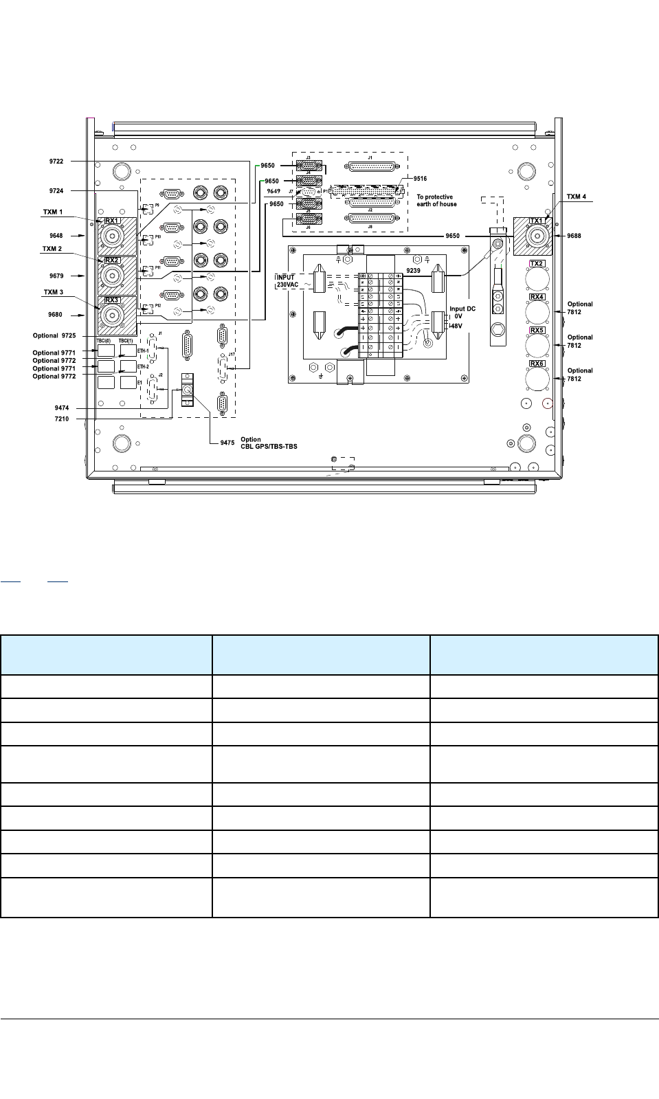
Thefollowinggureshowsacabinettopwiththemaximumnumber(4)ofTXantennamonitoringunits
(TXMs)whentwoduplexersareused.
DN04153465-08-3enTETRASystemRelease5.5–6.5-InstallingtheTB3
54(154)ThisdocumentisthepropertyofCassidianandshouldnotbecopiedorcirculatedwithoutpermission.
L1 L1
NN
L1L1 N N
9239
RX1
RX6
ETH-1
TBCi(0) TBCi(1)
RX2
9648
9679
9680
9722
9474
RX3
9516
J1
J2
J3
J4
J5
J6
J1
J8
P1
J7
TXM1
TXM2
TXM3
9650
9650
9650
ETH-2
E1
9688
TX1
TX2
RX4
RX5
J17
P12
P11
P10
P9
9724
Optional9771
Optional9772
Optional9772
Optional9771
7812
7812
7812
Optional
Optional
Optional
TXM4
9649
9650
9725
Optional
7210
9475 Option
CBL GPS/TBS-TBS
0V
-48V
InputDC
J2
Toprotective
earthofhouse
INPUT
230VAC
Figure20:Cabinettopinterfaceswhentwoduplexersareused
ThefollowingtablepresentsallthecabinettopconnectorsincludingtheonesnotdepictedinFigures
19and20.
Table13:Cabinettopconnectors
Interfaceconnectorname
writtenonthecabinetroof
InterfaceconnectorConnectortype
TX1TX1antennaconnector7/16connector,female
TX2TX2antennaconnector(optional)7/16connector,female
RX1RX1antennaconnector7/16connector,female
RX2RX2antennaconnector7/16connector,female
RX3RX3antennaconnector7/16connector,female
RX4RX4antennaconnector(optional)7/16connector,female
RX5RX5antennaconnector(optional)7/16connector,female
RX6RX6antennaconnector(optional)7/16connector,female
75ΩRx
75ΩTx
E175-ohmconnectorsBNCconnector,female
TETRASystemRelease5.5–6.5-InstallingtheTB3DN04153465-08-3en
ThisdocumentisthepropertyofCassidianandshouldnotbecopiedorcirculatedwithoutpermission.55(154)

Table13:Cabinettopconnectors(cont’d.)
Interfaceconnectorname
writtenonthecabinetroof
InterfaceconnectorConnectortype
100Ω/120ΩE1/T1100/120-ohmconnectors9-pinD-type,female
GPSIF1GPS15-pinD-type,female
GPSIF2GPS/TBS-TBS15-pinD-type,femaleor7210
terminator
Customercontrols0–7and
alarms0–35
CustomerAlarmsandcontrols
connectors
3x37-pinD-type,female
Q1IFExternalQ19–pinD-typefemale
LMPIFLMP9–pinD-typefemale
TXM1TXM19–pinD-typefemale
TXM2TXM29–pinD-typefemale
TXM3TXM39–pinD-typefemale
TXM4TXM49–pinD-typefemale
TBCi(0)ETH-1,ETH-2Ethernet8/8RJ45female
TBCi(1)ETH-1,ETH-2Ethernet8/8RJ45female
5.2Extensioncabinetinterfaces
Thetopcablingandconnectorsconsistofthefollowing:
•earthing
•AC/DCpowersupplyterminalblocks(ltermodule)
•TX/RXconnectors.
Thetopinterfacesareshownbelow.
DN04153465-08-3enTETRASystemRelease5.5–6.5-InstallingtheTB3
56(154)ThisdocumentisthepropertyofCassidianandshouldnotbecopiedorcirculatedwithoutpermission.
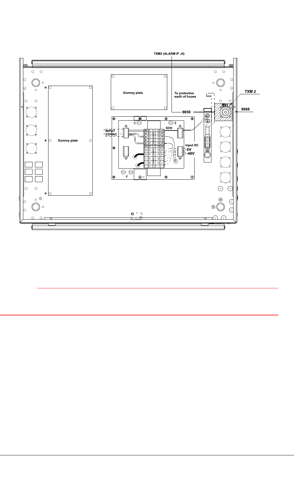
9650
InputDC
TX1
L1 L1
NN
L1L1 N N
9239
0V
-48V
Toprotective
earthofhouse
INPUT
230VAC
Dummyplate
Dummyplate
TXM2
TXM2(ALARMIFJ4)
9688
Figure21:Extensioncabinettopinterfaces
5.3Powersupply
WARNING
Mainsvoltage!Makesurethatthesitemainspowerisdisconnectedbeforemakingconnectionsto
thecabinet!
Thepersonconnectingthepowermustbeauthorizedtodosoasdenedinthenationallegislation.
Note
Removethecabinetroofframeandtheltermodulecoverandreplacethemaftertheinterface
connections.
Therearetwoalternativepowersupplyunits:
•PWR230AC(AC,230V).
•PWR-48VDC(DC,–48V).
TETRASystemRelease5.5–6.5-InstallingtheTB3DN04153465-08-3en
ThisdocumentisthepropertyofCassidianandshouldnotbecopiedorcirculatedwithoutpermission.57(154)

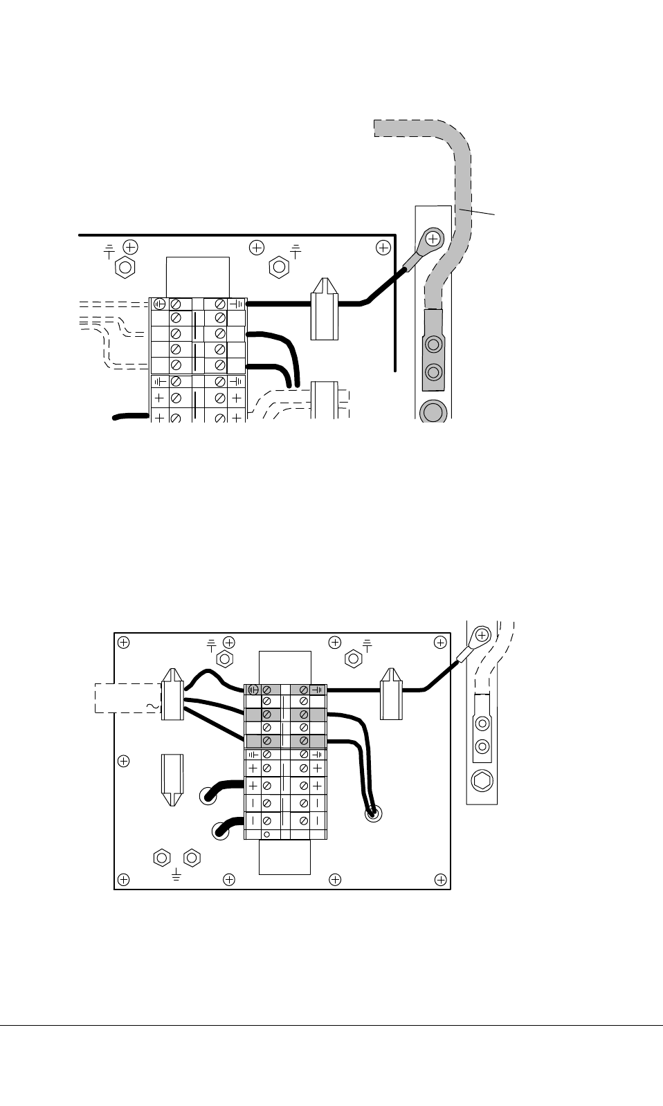
5.3.1Earthing
Note
Earththecabinetbeforemakinganyotherconnections!
Removethecabinetroofframeandtheltermodulecoverandreplacethemaftertheinterface
connections.
CheckgroundpotentialtoearthingbusbarbetweentheTBScabinetandthesiteearthingbusbar.
Thecabinetearthconnectorisacableshoewiththecablecross-sectionof16mm2.Thereisa
pre-installedearthcablebetweentheltermoduleandtheearthingbusbaronthecabinettop.
Toearththecabinet
1)Checkthatthepre-installedearthcablebetweentheltermoduleandtheearthingbaronthe
cabinettopiscorrectlyinstalled.
2)Stripthemainearthcableendfor1cm.
3)RemovethecableshoefromtheearthingbarwithaTorxkey.
4)Insertthestrippedendofthemainearthingcableintothecableshoeandcrimpwithacrimping
tool.
5)ReplacethecableshoetotheearthingbaroftheTBS.
6)Connectthemainearthingcabletotheprotectiveearthofthesite.
DN04153465-08-3enTETRASystemRelease5.5–6.5-InstallingtheTB3
58(154)ThisdocumentisthepropertyofCassidianandshouldnotbecopiedorcirculatedwithoutpermission.
N N
N NL1
L1
L1L1
9239
INPUT DC
0V
-48V
Earthing
cable
to protective
earth
dn05195122x1x0xen
Figure22:Earthingcableoncabinettop
5.3.2ConnectingACpower
Themaximumcablecross-sectionthatcanbeconnectedtotheACterminalblockis6mm2.The
minimumcablecross-sectionis2.5mm2.Dimensionofthecablecross-sectionmustfollowthenational
legislation.
dn00246739x1x0xen
INPUT
230VAC
N N
N
N
L1
L1
L1
L1
9239
Figure23:ConnectingACpowersupply
TETRASystemRelease5.5–6.5-InstallingtheTB3DN04153465-08-3en
ThisdocumentisthepropertyofCassidianandshouldnotbecopiedorcirculatedwithoutpermission.59(154)

ToconnecttheACpowertothecabinet
1)Checkthatthecabinetisproperlyearthed.
2)CutthethreewiresoftheACpowercablesothattheearthwireisabout2cmlongerthan
theothertwowires.
Stripthewiresfor1cm.
3)Inserttheearthwiretotheearthterminalandsecurethewiretotheterminalblockwitha
screwdriver.
4)Removetheplasticshieldsfromthe[N]and[L1]terminalsandloosenthescrewsoftheterminals.
5)Inserttheneutralwiretothe[N]terminalandsecurethewiretotheterminalblockwitha
screwdriver.
6)Insertthelivewiretothe[L1]terminalandsecurethewiretotheterminalblockwithascrewdriver.
7)Securethepowercablewiththecableclamp.
8)Replacetheplasticshieldsto[N]and[L1]terminals.
5.3.3DCpowersupply
Dimensionofthecablecross-sectionmustconformtonationalrequirements.
•Themaximumcablecross-sectionthatcanbeconnectedtotheDCterminalblockis25mm2.
•Theminimumrecommendedcablecross-sectionis16mm2.
Itisalsorecommendedthatfuturecapacity(powerconsumptiongrowth)isusedasaguidelinefor
selectingthecable.Currentsupto50AshouldbehandledbytheDCinputcabling.Alsocablelosses
mustbetakenintoaccountsothattheinputvoltagetotheTB3stayswellwithinspeciedvalues.
Approximatevoltagedropfortherst4.5mof16mm2cablewith50Aloadis0.5V.
DN04153465-08-3enTETRASystemRelease5.5–6.5-InstallingtheTB3
60(154)ThisdocumentisthepropertyofCassidianandshouldnotbecopiedorcirculatedwithoutpermission.
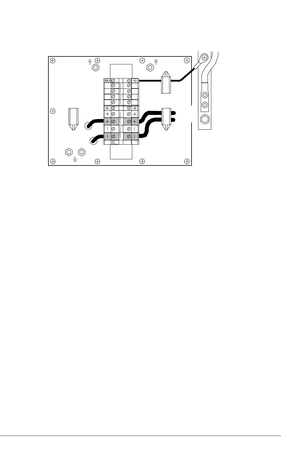
dn05195134x1x0xen
N N
N
N
L1
L1
L1
L1
INPUT DC
0V
-48V
9239
Figure24:ConnectingDCpowersupply
ToconnecttheDCpowertothecabinet
1)Checkthatthecabinetisproperlyearthed.
2)Stripthe[+]and[-]wiresfor1cm.
3)Removetheplasticshieldfromthe[+]and[-]terminalsandloosenthescrewsoftheterminals.
4)Insertthenegativewiretothe[-]terminalandsecurethewiretotheterminalblockwitha
screwdriver.
5)Insertthepositivewiretothe[+]terminalandsecurethewiretotheterminalblockwitha
screwdriver.
6)Securethewiresbythecableclamp.
7)Replacetheplasticshieldstothe[-]and[+]terminals.
TETRASystemRelease5.5–6.5-InstallingtheTB3DN04153465-08-3en
ThisdocumentisthepropertyofCassidianandshouldnotbecopiedorcirculatedwithoutpermission.61(154)
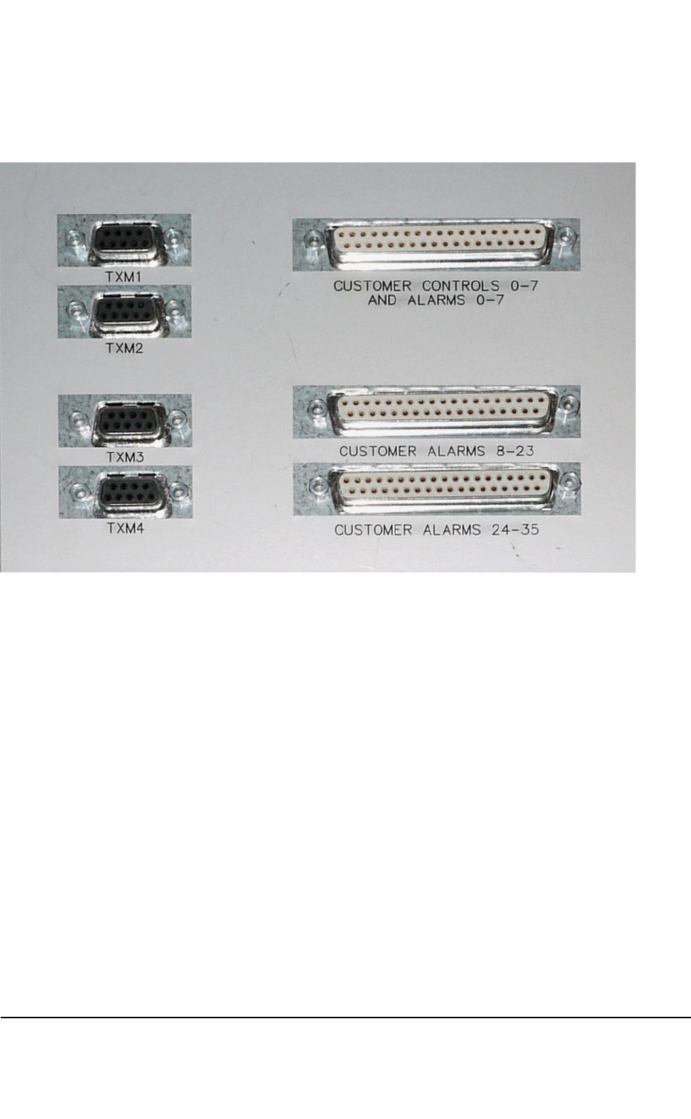
5.4Alarminterface(ALIF)
Figure25:Alarminterface
TheAlarminterfaceconnectscustomer-specicexternalalarminputsandcontroloutputstotheTB3.
Inadditiontotheexternalalarmsandcontrols,theALIFBprovidessupplyvoltageandsignalinterfaces
totheTXMunit.Thealarminterfaceislocatedonthetopofthecabinet.
TheAlarminterfacehasthefollowingexternalinterfaces:
•Customercontrols0–7andalarms0–7(J1):female37-pinD-connectorforexternalcontrols
andalarmlines.
•Customeralarms8–23(J2):female37-pinD-connectorforexternalalarmlines.
•Customeralarms24–35(J8):female37-pinD-connectorforexternalalarmlines.
•TXM1(J3),TXM2(J4),TXM3(J5),TXM4(J6):female9–poleD-connectorsforTXantennaline
monitoringsignallinesandsupplyvoltage.
DN04153465-08-3enTETRASystemRelease5.5–6.5-InstallingtheTB3
62(154)ThisdocumentisthepropertyofCassidianandshouldnotbecopiedorcirculatedwithoutpermission.

Table14:CustomerControlsandAlarms,J1
PinnumberSignalnameNote
01EXT_CO0Forcustomeruse
02EXT_CO1Forcustomeruse
03EXT_CO2Forcustomeruse
04EXT_CO3Forcustomeruse
05EXT_CO4Forcustomeruse
06EXT_CO5Forcustomeruse
07EXT_CO6Forcustomeruse
08EXT_CO7Forcustomeruse
09EXT_AL0Forcustomeruse
10EXT_AL1Forcustomeruse
11EXT_AL2Forcustomeruse
12EXT_AL3Forcustomeruse
13EXT_AL4Forcustomeruse
14EXT_AL5Forcustomeruse
15EXT_AL6Forcustomeruse
16EXT_AL7Forcustomeruse
17NC
18NC
19GNDForcustomeruse
20GNDForcustomeruse
21GNDForcustomeruse
22GNDForcustomeruse
23GNDForcustomeruse
24GNDForcustomeruse
25GNDForcustomeruse
26GNDForcustomeruse
27GNDForcustomeruse
28GNDForcustomeruse
29GNDForcustomeruse
30GNDForcustomeruse
31GNDForcustomeruse
TETRASystemRelease5.5–6.5-InstallingtheTB3DN04153465-08-3en
ThisdocumentisthepropertyofCassidianandshouldnotbecopiedorcirculatedwithoutpermission.63(154)

Table14:CustomerControlsandAlarms,J1(cont’d.)
PinnumberSignalnameNote
32GNDForcustomeruse
33GNDForcustomeruse
34GNDForcustomeruse
35NC
36NC
37GNDForcustomeruse
Table15:CustomerControlsandAlarms,J2
PinnumberSignalnameNote
01EXT_AL8Forcustomeruse
02EXT_AL9Forcustomeruse
03EXT_AL10Forcustomeruse
04EXT_AL11Forcustomeruse
05EXT_AL12Forcustomeruse
06EXT_AL13Forcustomeruse
07EXT_AL14Forcustomeruse
08EXT_AL15Forcustomeruse
09EXT_AL16Forcustomeruse
10EXT_AL17Forcustomeruse
11EXT_AL18Forcustomeruse
12EXT_AL19Forcustomeruse
13EXT_AL20Forcustomeruse
14EXT_AL21Forcustomeruse
15EXT_AL22Forcustomeruse
16EXT_AL23Forcustomeruse
17NC
18NC
19GNDForcustomeruse
20GNDForcustomeruse
21GNDForcustomeruse
DN04153465-08-3enTETRASystemRelease5.5–6.5-InstallingtheTB3
64(154)ThisdocumentisthepropertyofCassidianandshouldnotbecopiedorcirculatedwithoutpermission.

Table15:CustomerControlsandAlarms,J2(cont’d.)
PinnumberSignalnameNote
22GNDForcustomeruse
23GNDForcustomeruse
24GNDForcustomeruse
25GNDForcustomeruse
26GNDForcustomeruse
27GNDForcustomeruse
28GNDForcustomeruse
29GNDForcustomeruse
30GNDForcustomeruse
31GNDForcustomeruse
32GNDForcustomeruse
33GNDForcustomeruse
34GNDForcustomeruse
35NC
36NC
37GNDForcustomeruse
Table16:CustomerControlsandAlarms,J8
PinnumberSignalnameNote
01EXT_AL24Forcustomeruse
02EXT_AL25Forcustomeruse
03EXT_AL26Forcustomeruse
04EXT_AL27Forcustomeruse
05EXT_AL28Forcustomeruse
06EXT_AL29Forcustomeruse
07EXT_AL30Forcustomeruse
08EXT_AL31Forcustomeruse
09EXT_AL32Forcustomeruse
10EXT_AL33Forcustomeruse
11EXT_AL34Forcustomeruse
TETRASystemRelease5.5–6.5-InstallingtheTB3DN04153465-08-3en
ThisdocumentisthepropertyofCassidianandshouldnotbecopiedorcirculatedwithoutpermission.65(154)

Table16:CustomerControlsandAlarms,J8(cont’d.)
PinnumberSignalnameNote
12EXT_AL35Forcustomeruse
13NC
14NC
15TestsignalReservedfortesting,leaveopen
16TestsignalReservedfortesting,leaveopen
17NC
18NC
19GNDForcustomeruse
20GNDForcustomeruse
21GNDForcustomeruse
22GNDForcustomeruse
23GNDForcustomeruse
24GNDForcustomeruse
25GNDForcustomeruse
26GNDForcustomeruse
27GNDForcustomeruse
28GNDForcustomeruse
29GNDForcustomeruse
30GNDForcustomeruse
31GNDForcustomeruse
32GNDForcustomeruse
33GNDForcustomeruse
34GNDForcustomeruse
35NC
36NC
37GNDForcustomeruse
DN04153465-08-3enTETRASystemRelease5.5–6.5-InstallingtheTB3
66(154)ThisdocumentisthepropertyofCassidianandshouldnotbecopiedorcirculatedwithoutpermission.
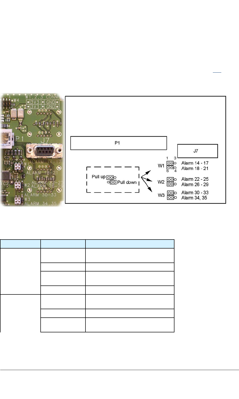
Jumpersettingsforcustomeralarms0-35
Customeralarmsignalsaredividedintotengroups(0-3,4-7,8-11,12-13,14-17,18-21,22-25,26-29,
30-33,and34-35).Eachofthealarmsignalgroups,exceptalarms12-13,canbeprovidedwitheithera
pull-uporpull-downresistor.Biasingingroups0-13isselectedbyjumpersontheTBCunit(see7.1).
Biasingingroups14-35areselectedbyjumperssituatedontheundersideoftheAlarminterfaceboard
(seegure27andtable16forinstructions).Defaultjumpersettingsaremarkedwithboldintable16.
Figure26:Alarminterfacejumpersettings
Table17:JumpersettingsforAlarminterface
JumpergroupPinsconnectedEffect
W11-2
(default)
biasingEXT_AL14-17high(+3.3V)
2–3biasingEXT_AL14-17low(ground)
5–6
(default)
biasingEXT_AL18-21high(+3.3V)
4–5biasingEXT_AL18–21low(ground)
W21-2
(default)
biasingEXT_AL22-25high(+3.3V)
2–3biasingEXT_AL22-25low(ground)
5–6
(default)
biasingEXT_AL26-29high(+3.3V)
TETRASystemRelease5.5–6.5-InstallingtheTB3DN04153465-08-3en
ThisdocumentisthepropertyofCassidianandshouldnotbecopiedorcirculatedwithoutpermission.67(154)
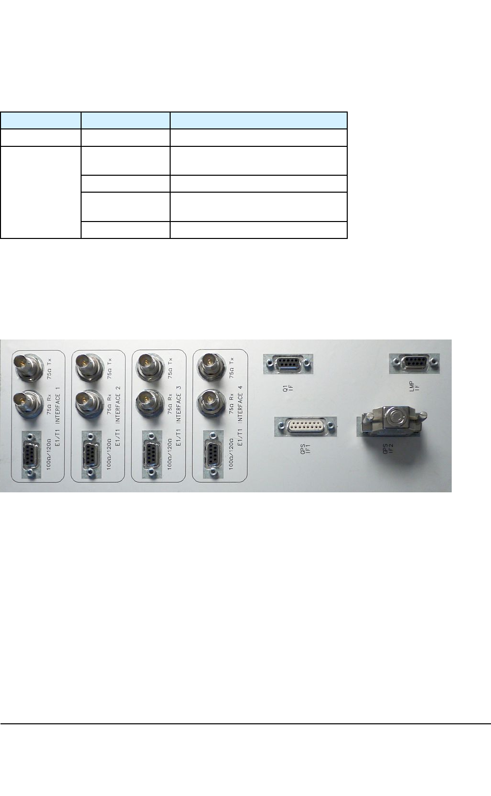
Table17:JumpersettingsforAlarminterface(cont’d.)
JumpergroupPinsconnectedEffect
4–5biasingEXT_AL26-29low(ground)
W31-2
(default)
biasingEXT_AL30-33high(+3.3V))
2–3biasingEXT_AL30-33low(ground)
5–6
(default)
biasingEXT_AL34–35high(+3.3V)
4–5biasingEXT_AL34–35low(ground)
5.5Transmissionunit(FXC)andtransmissionunitinterface
(FXCIF)
TheFXCinterfaceislocatedonthetopofthecabinet.
Figure27:FXCinterface
TheFXCIFhasthefollowingconnectorsforexternalinterfaces:
•fourfemale9pinD-connectorsforbalanced100/120–ohmE1/T1interfaces1–4
•eightfemaleBNCconnectorsforunbalanced75–ohmE1interfaces1–4(separateTXand
RXconnectors)
•onefemale9pinD-connectorforexternalQ1interface
•onefemale15pinD-connectorforGPSAntennaunitcable(GPSIF1)
•onefemale15pinD-connectorGPS/TBS-TBScable(GPSIF2)
•onefemale9pinD-connectorforoptionalLMPinterface.
DN04153465-08-3enTETRASystemRelease5.5–6.5-InstallingtheTB3
68(154)ThisdocumentisthepropertyofCassidianandshouldnotbecopiedorcirculatedwithoutpermission.
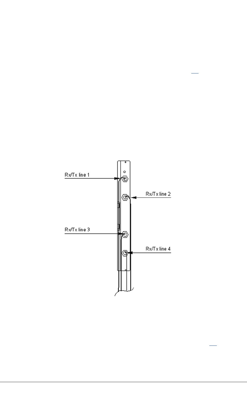
5.5.1ConnectingcablestotheFXCtransmissionunits
FXCE1/T1
TheFXCE1/T1unithasfour100/120ohmTx/Rxconnectors(typeTQ).SeeFigure28.
FormoreinformationontheFXCunitrefertothedocumentFXCE1andE1/T1TransmissionUnit
DescriptionforTETRA,dn05100057.
Steps
1)Connectthecables(code9724)fromtheFXCIFtothe100/120ohmTx/Rxconnectorson
theFXCE1/T1frontpanel.
2)Tightentheconnectornutproperly.Thetorqueneededis2Nm(1.5ft-lb).
3)Makesurethatthecableconnectorandshrinkingsleevecombinationisnottoolongsothatthe
cablehasenoughspacetobendwhenyouclosethecabinetdoor.
Figure28:CablingofFXCE1/T1unit
FXCE1
TheFXCE1unithasfourpairsof75ohmconnectors(typeBT-43).Eachpairformsatransmission
interface(IF).TheupperconnectorisalwaystheTxconnectorofanygiventransmissioninterface.The
lowerconnectorisalwaystheRxconnectorofanygiventransmissioninterface.SeeFigure29.
TETRASystemRelease5.5–6.5-InstallingtheTB3DN04153465-08-3en
ThisdocumentisthepropertyofCassidianandshouldnotbecopiedorcirculatedwithoutpermission.69(154)
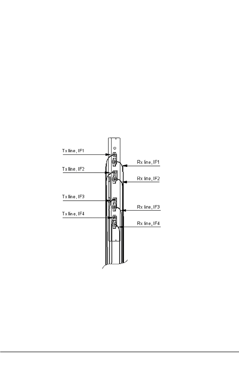
FormoreinformationontheFXCunitrefertoFXCE1andE1/T1TransmissionUnitDescriptionfor
TETRA,dn05100057.
Steps
1)Connectthecable(code9725)ofthereceived(Rx)signallinefromtheFXCIFtothe75ohmRx
connectorontheIF1.Notethatthecablescoded9710aresuppliedwiththeFXCE1unit.
2)Connectthecable(code9725)ofthetransmitted(Tx)signalfromtheFXCIFlinetothe75ohm
TxconnectorontheIF1.
3)CabletheotherIFsinthesamemanner.
4)Makesurethatthecableconnectorandshrinkingsleevecombinationisnottoolongsothatthe
cablehasenoughspacetobendwhenyouclosethecabinetdoor.
Figure29:CablingofFXCE1unit
GroundingtheRxconnector
ThegroundingoftheFXCE1’sRxconnectorisimplementedwithagroundingwasherundertheRx
connector.Itconnectstheoutmostwiresoftheconnector.
TogroundtheoutmostwireoftheRxconnectordirectly,leavethegroundingwasherinplace.
DN04153465-08-3enTETRASystemRelease5.5–6.5-InstallingtheTB3
70(154)ThisdocumentisthepropertyofCassidianandshouldnotbecopiedorcirculatedwithoutpermission.

TogroundtheoutmostwireoftheRxconnectorcapacitively,removethegroundingwasher.Loosenthe
connectorandpullthegroundingwasheroff.Storeitforfutureuse.
Note
ThegroundingoftheRXinterfaceontheFXCIFlocatedonthecabinettopmustcorrespondtothe
groundingmethodselectedontheRXconnectorsoftheFXCE1unit.RefertoSection5.5.4.
Note
Remembertotightentheconnectornutsproperlyafterthegroundingbridgehasbeenremoved!The
torqueis1.5Nm(1.11ft-lb).
5.5.2100/120–ohmE1/T1interface
TheconnectortypeofthefourE1/T1100/120–ohminterfacesusea9–pinfemaleD-connector.
Thepincongurationoftheconnectorsisdetailedinthetablebelow.
Table18:Pincongurationofthe100/120–ohmE1/T1interface
PinnumberDescriptionSignal(n=1–4)
1ReceiveE1/T1linesignalRXBALnA
2GroundGND
3GroundGND
4GroundGND
5TransmitE1/T1linesignalTXBALnA
6ReceiveE1/T1linesignalRXBALnB
7Notconnected
8Notconnected
9TransmitE1/T1linesignalTXBALnB
5.5.375–ohmE1interface
TheconnectortypeoftheE1interfaceisacoaxialfemaleBNCconnector.OntheFXCinterface,
theseinterfacesare:
TETRASystemRelease5.5–6.5-InstallingtheTB3DN04153465-08-3en
ThisdocumentisthepropertyofCassidianandshouldnotbecopiedorcirculatedwithoutpermission.71(154)
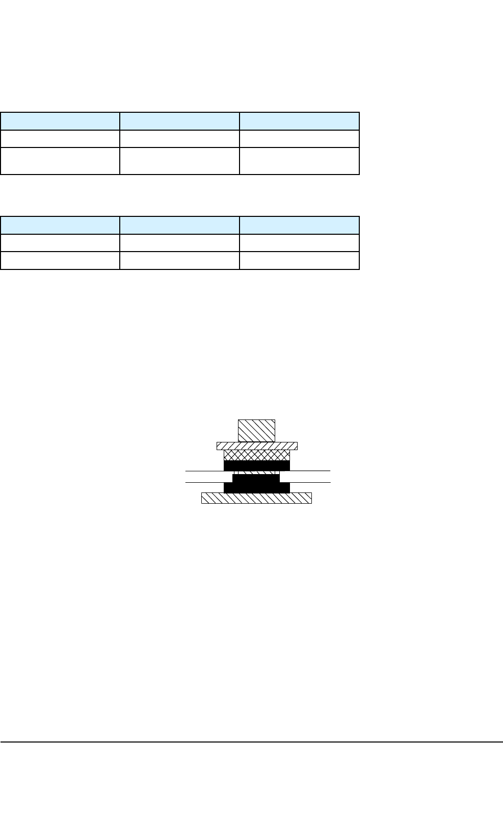
Table19:Receivingsignalpincongurationofthe75–ohmE1interface
PinnumberDescriptionSignal(n=1–4)
CentercontactReceiveE1LinesignalRXUNBn
OutercontactGroundRXGNDn
Table20:Transmittingsignalpincongurationofthe75–ohmE1interface
PinnumberDescriptionSignal(n=1–4)
CentercontactTransmitE1linesignalTXUNBn
OutercontactGroundGND
5.5.4GroundingtheFXCIF
TheFXC75-ohmRXinterfaceisgroundedontheFXCIFlocatedonthecabinettop.Theconnector
bodyisseparatedfromthecabinetearthwithcapacitorsasfactorydefault.
Groundingischangedfromcapacitancetogalvanicbyrearrangingtheorderofwashersinthe75-ohm
RXconnector.
UsethesettingsshownbelowwhentheTBSsareconnectedtodifferentearthingpoints.
Nut
Metal Washer
Plastic Washer
TBS Roof
Plastic Washer
BNC connector
dn00246836x1x0xen
Figure30:Capacitancegroundingof75-ohmRXconnectoronFXCIF
UsethesettingsshownbelowwhentheTBSsareconnectedtothesameearthingpoint.
DN04153465-08-3enTETRASystemRelease5.5–6.5-InstallingtheTB3
72(154)ThisdocumentisthepropertyofCassidianandshouldnotbecopiedorcirculatedwithoutpermission.
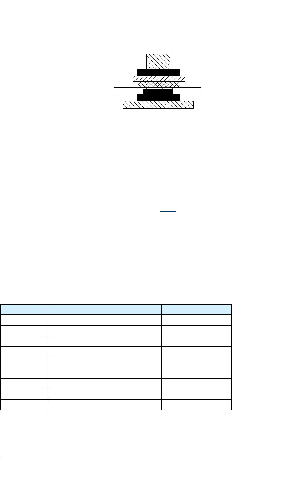
Stored Washer
Nut
Metal Washer
TBS Roof
Plastic Washer
BNC connector
dn00246848x1x0xen
Figure31:Galvanicgroundingof75-ohmRXconnectoronFXCIF
TorecongurethefourwasherpositionsontheFXCIF
1)UnscrewthenutoftheRXconnector.
2)Removethemetalandplasticwashers.
3)Replacethemetalwasher.
4)Repositionandtightenthenut.Storetheplasticwasherabovethenut.
SeealsotheT opicGroundingtheRxconnectorinSection5.5.1.
5.5.5ExternalQ1interfaceontheFXCinterface
TheconnectortypeoftheExternalQ1interfaceontheFXCinterfaceonthecabinettopisa9–pin
femaleD-connector.
TheExternalQ1interfacecanbeusedforconnectingexternalNSNspecicequipmenttotheTB3.
Reservedforfutureuse.
Table21:PincongurationoftheexternalQ1interface
PinnumberDescriptionSignal
1TransmitQ1interfacesignalQ1EXTD_N
2Notconnected
3GroundGND
4Notconnected
5ReceiveQ1interfacesignalQ1EXTU_N
6TransmitQ1interfacesignalQ1EXTD_P
7Notconnected
8Notconnected
9ReceiveQ1interfacesignalQ1EXTU_P
TETRASystemRelease5.5–6.5-InstallingtheTB3DN04153465-08-3en
ThisdocumentisthepropertyofCassidianandshouldnotbecopiedorcirculatedwithoutpermission.73(154)

5.5.6OptionalLMPinterface
TheLocalManagementPort(LMP)interfaceisanoptionalinterfacewhichenableslocalmanagement
oftheFXCunitwiththehelpofelementmanagersoftware.
Table22:PincongurationoftheoptionalLMPinterface
PinnumberDescriptionSignal
1Notconnected
2ReceiveLMPinterface
signal
LMP_IN
3TransmitLMPinterface
signal
LMP_OUT
4Notconnected
5GroundGND
6Notconnected
7Notconnected
8Notconnected
9Notconnected
5.5.7GPSIFconnectors
ThecablefromtheGPSantennaunitisconnectedtotheIF1connectorontheFXCIF.IftheGPS
signalisnottakentoanotherbasestationrack,theGPSterminator(DA7210)mustbeconnectedto
connectorIF2forterminatingtheGPSsignalbus.TheTBS-TBScable(code9475)isnecessaryif
theGPSsignalisfedfromoneTBS(IF2)tothenextTBSrack’sIF1connector.TheGPSterminator
(DA7210)mustbeconnectedtoconnectorIF2ofthesecondrackforterminatingtheGPScable.
Table23:GPSIF1andIF2pincongurations
Signal/GPSIF1PinSignal/GPSIF2
PWR_GPS11PWR_GPS2
BR1-2BR2-
BR1+3BR2+
BT1-4BT2-
BT1+5BT2+
—6—
DN04153465-08-3enTETRASystemRelease5.5–6.5-InstallingtheTB3
74(154)ThisdocumentisthepropertyofCassidianandshouldnotbecopiedorcirculatedwithoutpermission.

Table23:GPSIF1andIF2pincongurations(cont’d.)
—7—
AT1-8AT2-
GND9GND
AT1+10AT2+
PPS1+11PPS2+
PPS1-12PPS2-
5V_BIAS1135V_BIAS2
RESET114RESET2
—15—
5.6RFconnectors
Note
Tightenthe7/16connectorsto25Nm,Nconnectorsto1.2NmandtheSMAconnectorsto1Nm
torquewithatorquespanner.
RFconnectorswithcavitycombiners
Thefollowingantennaconnectionsareonthecabinettop:
•1–2TXand1–6RXantennaconnections
ThefollowingguresshowthedefaultcablingwithafullyequippedTB3withATC:
•Figure42
•Figure43
•Figure44
•Figure45
•Figure46
ThenumberofRXperTTRXcanvarybetweenoneandsix.ThenumberofDRMCunitsvarybetween
oneandthree.
RFconnectorswithduplexerandwidebandcombiner
Thefollowingantennaconnectionsareonthecabinettop:
•1...4TX/RXantennaconnections
TETRASystemRelease5.5–6.5-InstallingtheTB3DN04153465-08-3en
ThisdocumentisthepropertyofCassidianandshouldnotbecopiedorcirculatedwithoutpermission.75(154)

Figure57showsfrontcablingfora2–carrierTB3withWBCandDDUwithFXCE1andFigure43
showsfrontcablingfora2–carrierTB3withWBCandDDUwithFXCE1/T1.
Note
DuplexercanbeusedwithorwithoutDRMC.
Note
DonotconnectthecablestotheSMA-connectorsintheDDU,DRMCorDDIVunitsiftheTTRX-endof
thecablewillremainopen.AllunusedSMA-connectorsintheDDU,DRMCorDDIVunitsmustbe
terminatedwitha50ohmterminator.Terminatorsaredeliveredwiththecabinet.
DN04153465-08-3enTETRASystemRelease5.5–6.5-InstallingtheTB3
76(154)ThisdocumentisthepropertyofCassidianandshouldnotbecopiedorcirculatedwithoutpermission.
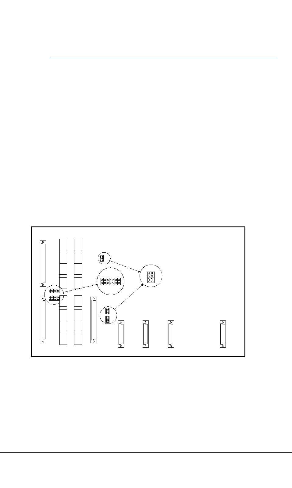
CHAPTER
6
Settingsofsubracks
6.1Commonsubrack(CSR)jumpers
TheCommonSubrack(CSR)hasjumpersfortheTBSHWconguration,12.96MHzsystemclock
termination,andD-bustermination.NotethatTBC1andTBC2mustbeidenticallyjumpered.The
jumpersareaccessibleviathesubrackfront.
J8
J9
P1
P2
P3
P4
P5
P6
P7
P8
J4
J10 J11 J12 J13
FXCA/
FXC TBC1 TBC2
OPT1
RMC1 RMC2 RMC3 OPT2
JP2
JP1
JP3
1
3
5
7
2
4
6
8
JP1-3
JP4
JP5
1 3 5 7
2 4 6 8
JP4-5
91113
101214
Figure32:CSRjumpers
TETRASystemRelease5.5–6.5-InstallingtheTB3DN04153465-08-3en
ThisdocumentisthepropertyofCassidianandshouldnotbecopiedorcirculatedwithoutpermission.77(154)
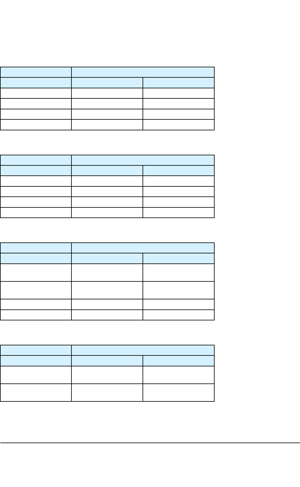
Table24:JP1jumperinginthebasiccabinet
JumperJP1usage
PinnumbersDescriptionSetting
1–2NotusedJumperoff
3–4NotusedJumperoff
5–6NotusedJumperoff
7–8NotusedJumperoff
Table25:JP2jumperinginthebasiccabinet
JumperJP2usage
PinnumbersDescriptionSetting
1–2NotusedJumperoff
3–4NotusedJumperoff
5–6NotusedJumperoff
7–8NotusedJumperoff
Table26:JP3jumperinginthebasiccabinet
JumperJP3usageinsinglecabinetconguration
PinnumbersDescriptionSetting
1–212.96MHzclock
termination
Jumperon
3–412.96MHzclock
termination
Jumperon
5–6NCJumperoff
7–8NCJumperoff
Table27:JP3jumperinginthebasiccabinetwithextensioncabinetconguration
JumperJP3usagewithextensioncabinetconguration
PinnumbersDescriptionSetting
1–212.96MHzclock
termination
Jumperoff
3–412.96MHzclock
termination
Jumperoff
DN04153465-08-3enTETRASystemRelease5.5–6.5-InstallingtheTB3
78(154)ThisdocumentisthepropertyofCassidianandshouldnotbecopiedorcirculatedwithoutpermission.

Table27:JP3jumperinginthebasiccabinetwithextensioncabinetconguration(cont’d.)
JumperJP3usagewithextensioncabinetconguration
PinnumbersDescriptionSetting
5–6NCJumperoff
7–8NCJumperoff
Table28:JP4&JP5jumperinginthebasiccabinet
JumperPinsDescription
JP4
JP5
1–2
13–14
SYNC-termination
SYNC+termination
JP43–4
5–6
RDAT1+termination
RDAT1–termination
JP47–8
9–10
TDAT1+termination
TDAT1–termination
JP411–12
13–14
MFCLK+termination
MFCLK–termination
JP51–2
3–4
CK2M+termination
CK2M–termination
JP55–6
7–8
RDAT2+termination
RDAT2–termination
JP59–10
11–12
TDAT2+termination
TDAT2–termination
Setting
Allpinsofbothjumpersneedtobejumpered(defaultsetting)whenan
extensioncabinetisnotused.Removealljumperswhenanextensioncabinet
istakenintouse.
ThereisnoneedtojumpertheCSRintheextensioncabinet.
6.2TETRAtransceiversubrack(TRXSR)jumpers
Thesubrackaddresscanbeselectedbymeansofjumpers.Inthebasicsubrack,bothjumpersare
insertedandintheextensionsubrackADDR3jumpered.Thesubrackjumpersareaccessiblevia
thesubrackfront.
TETRASystemRelease5.5–6.5-InstallingtheTB3DN04153465-08-3en
ThisdocumentisthepropertyofCassidianandshouldnotbecopiedorcirculatedwithoutpermission.79(154)

dn00246875x2x0xen
Pin1
W2 W1
TRXSR
W1/1-W2/1 Address bit ADDR2 of TTRX subrack
W1/2-W2/2 Address bit ADDR3 of TTRX subrack
Jumpers of basic cabinet's TTRX subrack (default):
W1/1-W2/1 jumpered
W1/2-W2/2 jumpered
Jumpers of extension cabinet's (TBS with 8 channels) TTRX subrack:
W1/1-W2/1 no jumpers
W1/2-W2/2 jumpered
Figure33:TRXSRjumpers
6.3Powersubrack(PWSR)fuses
Resetthefusesbypressingthebuttonsonthefuses.
Thesubrackfusesareaccessibleviathesubrackfront.
DN04153465-08-3enTETRASystemRelease5.5–6.5-InstallingtheTB3
80(154)ThisdocumentisthepropertyofCassidianandshouldnotbecopiedorcirculatedwithoutpermission.

dn05225143x2x0xen
F5
F1
F2
F3
PWSR
Fuses (reset type):
F1 +12 V power supply common subrack
F2 +26 V power supply to ATC and fans
F3 +26 V power supply to common subrack
F5 +5 V power supply to common subrack
Figure34:PWSRfuses
CAUTION
Donotresetthefuseswiththepowerturnedon.
TETRASystemRelease5.5–6.5-InstallingtheTB3DN04153465-08-3en
ThisdocumentisthepropertyofCassidianandshouldnotbecopiedorcirculatedwithoutpermission.81(154)

PAGEINTENTIONALLYLEFTBLANK
DN04153465-08-3enTETRASystemRelease5.5–6.5-InstallingtheTB3
82(154)ThisdocumentisthepropertyofCassidianandshouldnotbecopiedorcirculatedwithoutpermission.

CHAPTER
7
Unitinstallationinstructions
Generalprocedures
ThischaptergivesinstructionsforinstallingunitsinTB3.UnitcablinginstructionsareinChapters
5.5.1and8.TheMaintenanceofTETRABaseStations,dn00132139manualalsohasinstructions
forworkingwiththeunitsoftheTBS.Formoreinstructionshowtohandletheplug-inunits,referto
ReplacingPlug-inUnitsandOtherHardwareUnits,dn98613521.
Alwayspayattentiontothefollowing:
•ReadthesafetyinstructionsinChapter3.
•WearanantistatichandstrapconnectedtotheESDstudoftheTBSwheneverhandling
electrosensitiveunits.YoucanidentifytheelectrosensitiveunitsbytheESDsignontheunit
frontpanel.
•Notethatsomeunits(TBC,DRMC)needchecking/settingofjumpers.
•SomeunitslikeTTRX,DDU,PSU,andcombinersareheavyandmayhavesharpedges.
•Handleunitswithcareandfastenallretainingscrews(butdonotovertighten)toensurethatthe
unitsarewellseatedinthesubracks.
•Afterinstallingtheunits,seethattheemptyslotshavebeencoveredbydummyplates.
•Keepsomeofpackingmaterialincaseaunitneedstobereplacede.g.duetotransportation
damage.
TETRASystemRelease5.5–6.5-InstallingtheTB3DN04153465-08-3en
ThisdocumentisthepropertyofCassidianandshouldnotbecopiedorcirculatedwithoutpermission.83(154)

7.1TBCunit
ThissectiondetailstheinstallationandjumpersettingsintheTETRABaseStationControllerunit
(TBC).TherearetwovariantsoftheTBCunit:TBC-UandTBCi.
Note
OnlyonetypeofTBCunitscanbeinstalledinoneTB3atatime:TBC-UorTBCi.
7.1.1TBC-U
CAUTION
WearanantistatichandstrapconnectedtotheESDstudwhenhandlingtheTBC-Uunit.Theunitis
susceptibletodamagecausedbystaticelectricity.
Alwayscheckthejumpersettingsbeforeinstallationandchangethemifthedefaultsettingsare
inappropriate.
CAUTION
Handletheunitwithcare.Usethetopandbottomhandlesforliftingandforpushingtheunitinto
thecabinet.
DN04153465-08-3enTETRASystemRelease5.5–6.5-InstallingtheTB3
84(154)ThisdocumentisthepropertyofCassidianandshouldnotbecopiedorcirculatedwithoutpermission.

6 4
1 3
6 4
1 3
6 4
1 3
W1 W2 W3
W4
dn0568386x1x0xen
8 5
1 4
Figure35:TBC-Udefaultjumpersettings
Note
UseonlythemandatorysettingsforjumpersW21–2,5–6andW31–2inthetablebelow(internallines
biasing).TheremainingEXT_ALlinesbiasingcanbefreelyselected.
TETRASystemRelease5.5–6.5-InstallingtheTB3DN04153465-08-3en
ThisdocumentisthepropertyofCassidianandshouldnotbecopiedorcirculatedwithoutpermission.85(154)

Table29:TBC-Ujumpersettings
JumpergroupPinsconnectedEffect
W11-2
(default)
biasingEXT_AL4-7high(+5V)
2–3biasingEXT_AL4-7low(ground)
5–6
(default)
biasingEXT_AL0-3high(+5V)
4–5biasingEXT_AL0-3low(ground)
W21-2
(mandatory)
SeeNoteabove!
biasinginternalsignalsforTXM4
andALIFserialdatahigh(+5V)
2–3biasinginternalsignalsforTXM4and
ALIFserialdatalow(ground)
5–6
(mandatory)
SeeNoteabove!
biasinginternalsignalsforTXM2
andTXM3high(+5V)
4–5biasinginternalsignalsforTXM2and
TXM3low(ground)
W31-2
(mandatory)
SeeNoteabove!
biasingEXT_AL12-13andinternal
signalsforTXM1high(+5V)
2–3biasingEXT_AL12-13andinternal
signalsforTXM1low(ground)
5–6
(default)
biasingEXT_AL8–11high(+5V)
4–5biasingEXT_AL8–11low(ground)
W41-8disableredundancybysettingthe
jumperingon
2–7enablebootashprogrammingby
settingthejumperingon
3–6disablewatchdogbysettingthe
jumperingon
4–5NA
DN04153465-08-3enTETRASystemRelease5.5–6.5-InstallingtheTB3
86(154)ThisdocumentisthepropertyofCassidianandshouldnotbecopiedorcirculatedwithoutpermission.
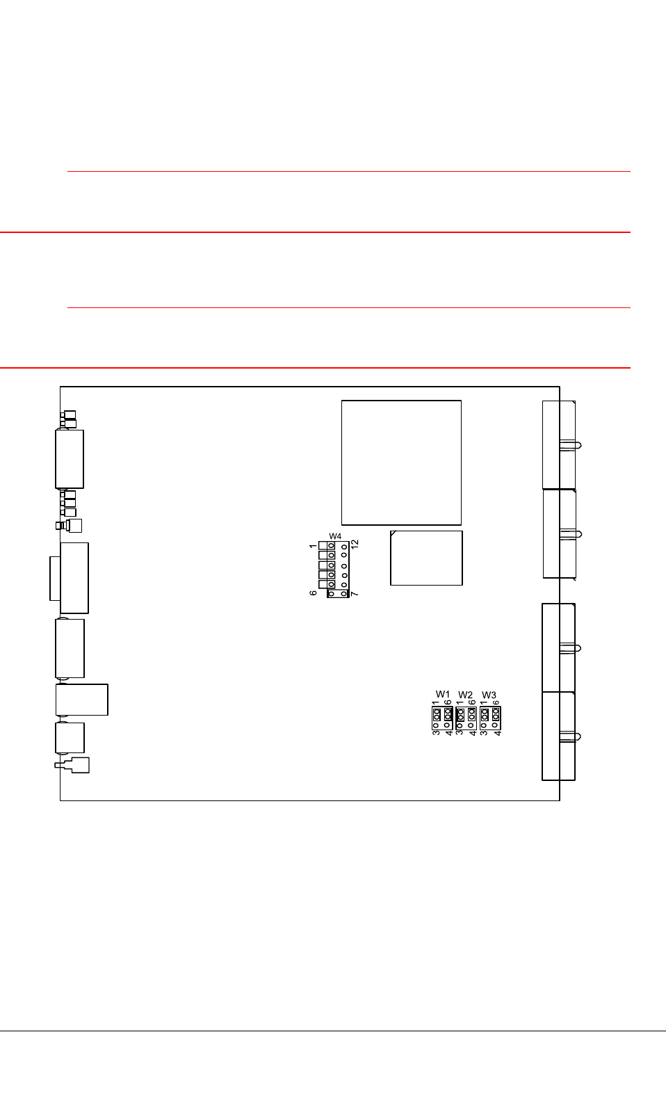
7.1.2TBCi
CAUTION
WearanantistatichandstrapconnectedtotheESDstudwhenhandlingtheTBCiunit.Theunitis
susceptibletodamagecausedbystaticelectricity.
Alwayscheckthejumpersettingsbeforeinstallationandchangethemifthedefaultsettingsare
inappropriate.
CAUTION
Handletheunitwithcare.Usethetopandbottomhandlesforliftingandforpushingtheunitinto
thecabinet.
W4
W1 W2 W3
6
6
6
3
4
6
3
4
3
4
7
1
12
1
1
1
Figure36:TBCidefaultjumpersettings
TETRASystemRelease5.5–6.5-InstallingtheTB3DN04153465-08-3en
ThisdocumentisthepropertyofCassidianandshouldnotbecopiedorcirculatedwithoutpermission.87(154)

Note
UseonlythemandatorysettingsforjumpersW21–2,5–6andW31–2inthetablebelow(internallines
biasing).TheremainingEXT_ALlinesbiasingcanbefreelyselected.
DN04153465-08-3enTETRASystemRelease5.5–6.5-InstallingtheTB3
88(154)ThisdocumentisthepropertyofCassidianandshouldnotbecopiedorcirculatedwithoutpermission.

Table30:TBCijumpersettings
JumpergroupPinsconnectedEffect
W11-2
(default)
biasingEXT_AL4-7high(+5V)
2–3biasingEXT_AL4-7low(ground)
5–6
(default)
biasingEXT_AL0-3high(+5V)
4–5biasingEXT_AL0-3low(ground)
W21-2
(mandatory)
SeeNoteabove!
biasinginternalsignalsforTXM4
andALIFserialdatahigh(+5V)
2–3biasinginternalsignalsforTXM4and
ALIFserialdatalow(ground)
5–6
(mandatory)
SeeNoteabove!
biasinginternalsignalsforTXM2
andTXM3high(+5V)
4–5biasinginternalsignalsforTXM2and
TXM3low(ground)
W31-2
(mandatory)
SeeNoteabove!
biasingEXT_AL12-13andinternal
signalsforTXM1high(+5V)
2–3biasingEXT_AL12-13andinternal
signalsforTXM1low(ground)
5–6
(default)
biasingEXT_AL8–11high(+5V)
4–5biasingEXT_AL8–11low(ground)
W41-12NA
2-11disableredundancybysettingthe
jumperingon
3-10connectSERVtofrontplatebysetting
thejumperingon
4–9connectConsoletofrontplateby
settingthejumperingon
5–8disablex86watchdogbysettingthe
jumperingon
6–7
(default)
disablePPCwatchdogbysettingthe
jumperingon
TETRASystemRelease5.5–6.5-InstallingtheTB3DN04153465-08-3en
ThisdocumentisthepropertyofCassidianandshouldnotbecopiedorcirculatedwithoutpermission.89(154)
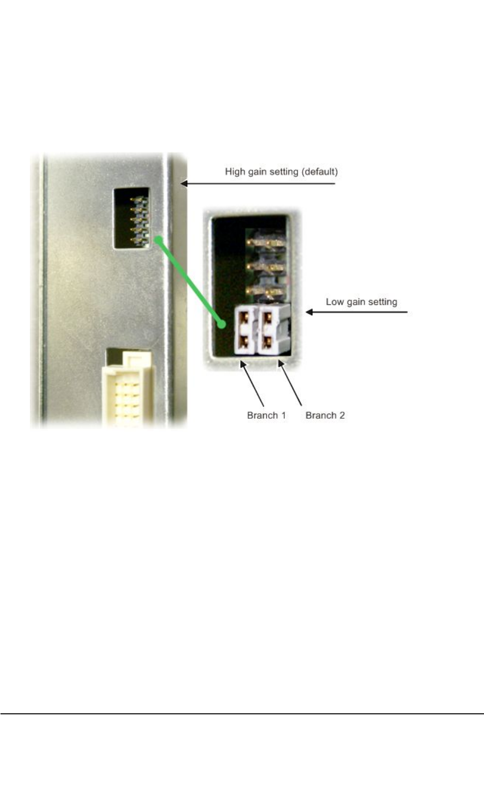
7.2DRMCunitjumpersettings
IncaseMHAisused,itispossibletoreduceRXpathgainintheDRMCbyswitchingtheinternal10dB
step-attenuatorbythejumpersettingsatthebacksideoftheDRMCunit.Seethefollowinggure.
Figure37:DRMCjumpersettingshigh/lowgain
Whenthejumpersarenotinstalled(defaultsetting),bothDRMCbranchesareinahighgainmode.
Whenthejumperisinstalled,thebranchinquestionisswitchedtolowgainmode.
7.3ATCinstallation
Beforetheinstallation
Beforeyoustarttheactualinstallation,dothefollowing:
1.Removethecombinerfromthepacking.
2.Checkthatthecombinerhasnotbeendamagedduringtransportation.
Ifthecombinerisdamaged,returnitforrepairandleaclaimreport.
DN04153465-08-3enTETRASystemRelease5.5–6.5-InstallingtheTB3
90(154)ThisdocumentisthepropertyofCassidianandshouldnotbecopiedorcirculatedwithoutpermission.
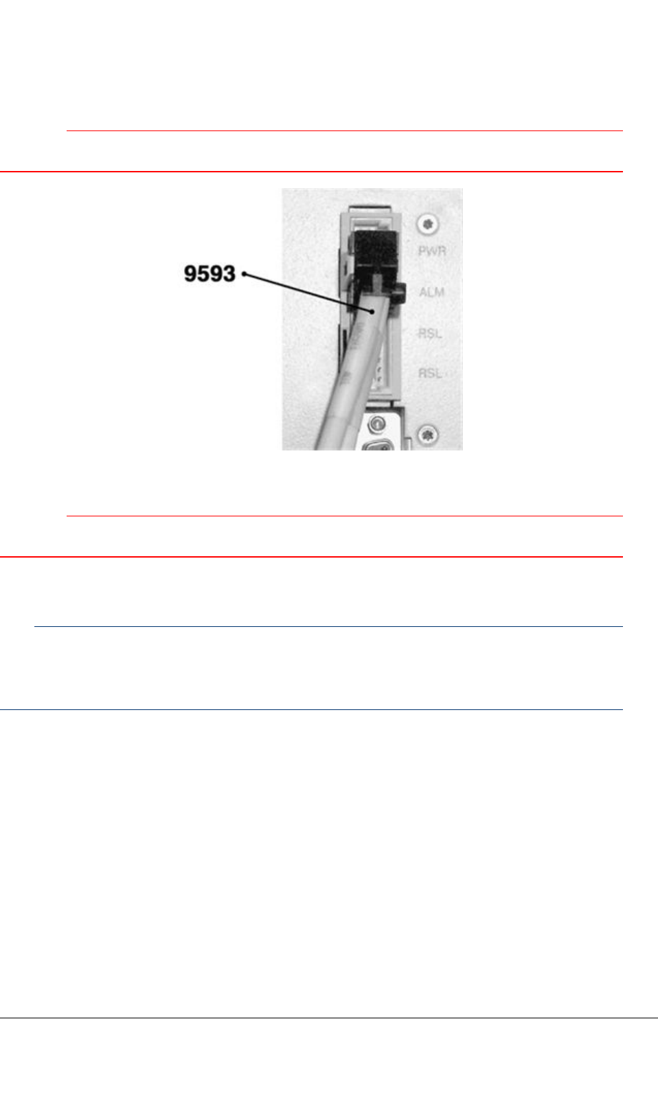
CAUTION
Checkthecablelabelsandpossiblesitespecicinstructionstoensurecorrectcableconnections.
Figure38:CablingtoEuroconnector
CAUTION
Connectingthealarmandpwrcableincorrectlymaydamagethecombiner.
Toinstallthecombiner
Note
ItisnotrecommendedtoinstallATC380unitsfromdifferentvendorsinthesamecabinet.Ifyouneed
todoit,installtheunitfromCombilent(withheatsinksonthefrontpanel)belowtheunitfromKathrein
toensureproperairowtotheheatsinksonthefront.
1)Slidethecombinerintothebasestationrack.
2)Usingthefourrackscrews,xthecombinertotherack.
3)Removetheprotectivecapsfromtheconnectors.
4)Connectthefollowingcablestothecombiner:
•Basestationinterfacecable
•Antennacable
•TXcableNo.1
•TXcableNo.2
TETRASystemRelease5.5–6.5-InstallingtheTB3DN04153465-08-3en
ThisdocumentisthepropertyofCassidianandshouldnotbecopiedorcirculatedwithoutpermission.91(154)

Thecombinerisnowreadyforuse.
Whenthepowersupplyofthebasestationisturnedon,thecombinerturnsonautomatically.The
greenLED(markedOPR)onthefrontpanellightsup,indicatingthatthecombinerreceivesDCpower
andisoperative.
Asarstactionitisrecommendedthatyouparkthecavities:presstheRESETbuttononthefrontpanel.
TheyellowLED(markedALM)andthegreenLEDwillbothlightup,indicatingthatthecavitiesare
parkedandthattheDCpowerison.
7.3.1Troubleshooting
SeethedocumentAuto-tunedCombinersforTBS,dn00132115.
7.4WBCandDDUinstallation
Beforetheinstallation
Beforeyoustarttheactualinstallation,dothefollowing:
1.Removethecombinerandduplexerfromtheirpackings.
2.Checkthatthecombinerandduplexerhavenotbeendamagedduringtransport.
Ifeitherofthemisdamaged,returnitforrepairandleaclaimreport.
CAUTION
Checkthecablelabelsandpossiblesitespecicinstructionstoensurecorrectcableconnections.
Connectthe9593combinercablessothatwhenoneDDUisused,thecablemarkedCB1isconnected
toit.IftwoDDUsareused,connectthecablemarkedCB1toDDU1(lower)andcablemarkedCB2to
DDU2(upper).
CAUTION
ConnectingthealarmandpowercableincorrectlymaydamagetheDDU.
WARNING
Heavyweight.BecarefulwhenhandlingtheDDU.
ToinstallthecombinerandDDU
1)SlidethecombinerandDDU(bysupportingitfromthebottom)intothebasestationrack.
2)Usingthefourrackscrews,xthecombinerandDDUtotherack.
3)Removetheprotectivecapsfromtheconnectors.
DN04153465-08-3enTETRASystemRelease5.5–6.5-InstallingtheTB3
92(154)ThisdocumentisthepropertyofCassidianandshouldnotbecopiedorcirculatedwithoutpermission.
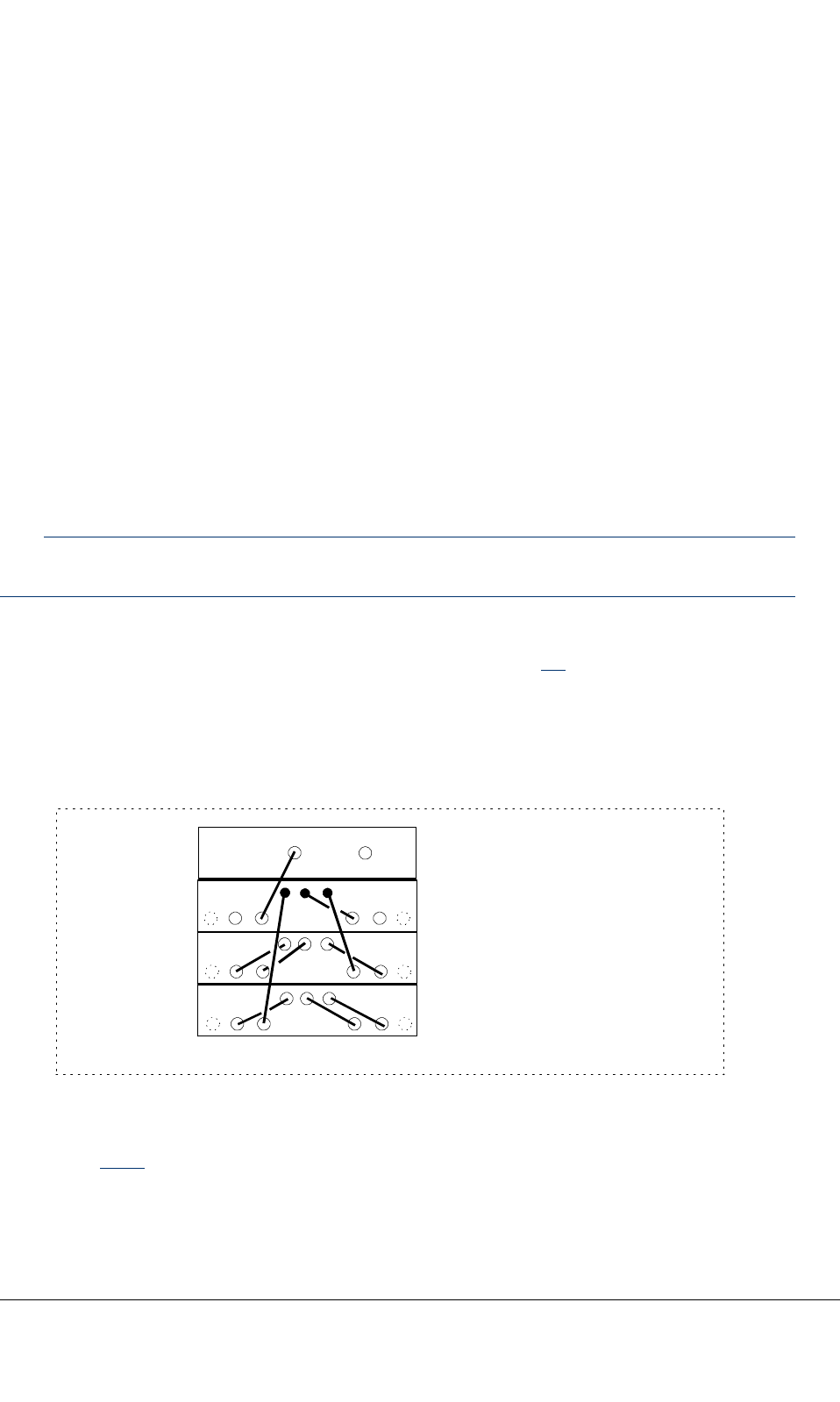
4)Connectthefollowingcablestothecombiner:
•TXcableNo1.
•TXcableNo2.
•WBC-DDUcable(s)1...2.
•Basestationinterfacecable(cablemarkedCB1toDDU1).
•DDU-TTRXRXcable(s)1...8.(Connectonlythosecablesthatwillbeusedandterminate
allunusedSMA-portsintheDDUwitha50ohmterminator.)
•Antennacable(s)1...2.
ThecombinerandDDUarenowreadyforuse.
Whenthepowersupplyofthebasestationisturnedon,theDDUturnsonautomatically.ThegreenLED
(markedOPR)onthefrontpanellightsup,indicatingthattheDDUreceivesDCpowerandisoperative.
Note
UnusedDDUoutputsneedtobeterminated.
Ifyouareusing3–4carrierswithasingleantenna,connecttheWBCunitsusingtheinbuiltcablesin
theWBCunits.Tomaketheconnection,dothefollowing(seeFigure39):
1.OpentheHYBIN1(inbuilt)cablefromtheIsolator1OUTconnectorintheWBC3andconnectit
totheHYBOUT1connectorintheWBC1.
2.OpentheHYBIN2(inbuilt)cablefromtheIsolator2OUTconnectorintheWBC3andconnectit
totheHYBOUT2connectorintheWBC2.
3-4 channels:
TX1 TX2
ISOLATOR1
OUT
ISOLATOR2
OUT
HYB
OUT1
HYB
OUT2
DDU1
WBC1
WBC2
WBC3
WBC 4:1
dn0600631
Figure39:3–4carrierswithoneantenna
SeeSection8.2.5forinformationhowtoaddmorechannels.
TETRASystemRelease5.5–6.5-InstallingtheTB3DN04153465-08-3en
ThisdocumentisthepropertyofCassidianandshouldnotbecopiedorcirculatedwithoutpermission.93(154)

7.4.1Troubleshooting
ThefollowingtableshowsthefaultindicationsforDDU380andDDU385.
Table31:FaultindicationsforDDU380andDDU385
FaultindicationPossiblecausesRecovery
TheLEDisOFFThepowersupplymaynotbe
properlyconnected.
Connectthepowersupply
properly.
ThefuseinsidetheDDUmay
beblown.
ReturntheDDUforrepair.
TheLEDisredFailureintheLNAinoneor
bothhalvesoftheDDU.
ReturntheDDUforrepair.
TBCreportsbothMHA1and
MHA2alarms
WrongHWcongurationat
TBC.
CheckthatMHAshavenot
beenconguredinTBCif
theyarenotused.
7.5TXantennamonitoringunit(TXM)
TXM(s)areusedformonitoringTXantennalinecondition.BasiccabinetsupportstheuseoffourTXMs
mountedonthebasestation’sTX-connector(s)locatedontheroofofthebasestationcabinet(s).The
antennalineismonitoredbymeasuringitsforwardandreversepowerwithdirectionalcouplerand
detectorcircuit.Detectorcircuitisatrue-RMStypeandhaslinear-in-dBresponse.Theunitgenerates
twoanalogoutputsignals:oneforforwardpower(FWD)andanotherforreversepower(REV).
TheTXMhastwofrequencyvariants:
•336-470MHzvariantforTB3350,TB3380,TB3410andTB3450
•851-869MHzvariantforTB3800
SeethefollowingguretoseetheTXManditsconnectors.
DN04153465-08-3enTETRASystemRelease5.5–6.5-InstallingtheTB3
94(154)ThisdocumentisthepropertyofCassidianandshouldnotbecopiedorcirculatedwithoutpermission.
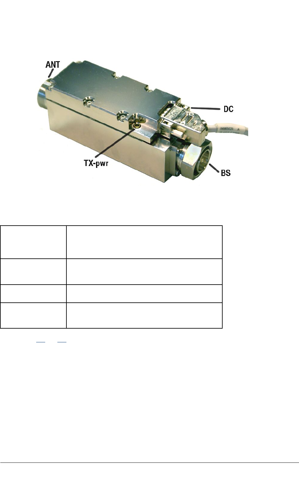
Figure40:TX-antennamonitoringunit(TXM)
Table32:TXMconnectors
BSconnector7/16male
UsedformountingTXM(s)onthebasestation’s
antennaconnector(s)locatedontheroofofthebase
stationcabinet.
ANTconnector7/16female
UsedforconnectingtheTB3antennacabletothe
TXM(s).
DCconnectorFemale9-pinsubD-connector
Cable9650toAlarminterface(ALIFB)
TX-PWRconnectorMCXfemale
Normallyunconnected.Canbeusedforonline
monitoringpurpose.
SeeFigures19and20.
TETRASystemRelease5.5–6.5-InstallingtheTB3DN04153465-08-3en
ThisdocumentisthepropertyofCassidianandshouldnotbecopiedorcirculatedwithoutpermission.95(154)

PAGEINTENTIONALLYLEFTBLANK
DN04153465-08-3enTETRASystemRelease5.5–6.5-InstallingtheTB3
96(154)ThisdocumentisthepropertyofCassidianandshouldnotbecopiedorcirculatedwithoutpermission.
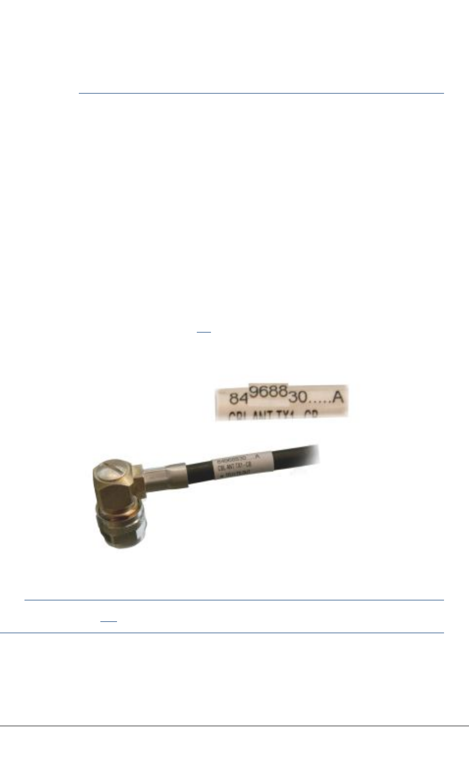
CHAPTER
8
Internalcabling
Thecabinetsaredeliveredwithpreinstalledinternalcabling.Normallyonlyexternalandunitfront
panelcablesneedtobeconnected.
Everycablecarriesalabelwhichgivesyouthefour-digitcablecode,the3rd–6thinthenumber
sequenceofthelabel(inthefollowingFigure41,forexample,thecablecodeis9688).
Figure41:Cablecodelabel
Note
ReadcarefullySection3.1ofthisdocumentbeforecommencinginstallationofcables.
TETRASystemRelease5.5–6.5-InstallingtheTB3DN04153465-08-3en
ThisdocumentisthepropertyofCassidianandshouldnotbecopiedorcirculatedwithoutpermission.97(154)

Usethesite-specicInstallationCheckListtorecordthecompletionoftasksdetailedinthisdocument.
AnexampleoftheInstallationCheckListcanbefoundattheendofthismanual.
CAUTION
Takecarenottobendcablesunnecessarily.Checkalsothatthereisenoughroomforclosingthe
cabinetdoor.ImproperhandlingmayaffectRFcharacteristicsanddamageconnectors.
8.1Cavitycombiners
CAUTION
TakecarenottobendcombinerRFcablesunnecessarily.Checkalsothatthereisenoughroomfor
closingthecabinetdoor.ImproperhandlingmayaffectRFcharacteristicsanddamageconnectors.
CAUTION
Checkthecablelabelsandpossiblesitespecicinstructionstoensurecorrectcableconnections.
8.1.1Cabinetfrontcabling(4-carrierTB3withATC)
Refertopossiblesite-specicinstructionsforcabling.Thecablecodesandquantitymaydifferfromthe
followinggure.
DN04153465-08-3enTETRASystemRelease5.5–6.5-InstallingtheTB3
98(154)ThisdocumentisthepropertyofCassidianandshouldnotbecopiedorcirculatedwithoutpermission.
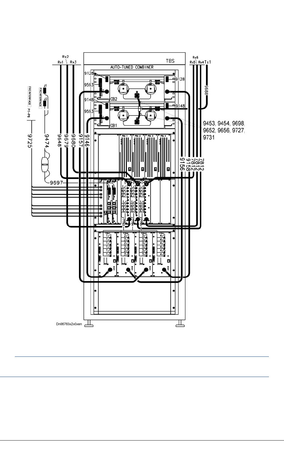
Figure42:Frontcablingfora4-carrierTB3withATC(FXCE1)
Note
Cables9128and9148arenotusedwithATC380andATC800.
TETRASystemRelease5.5–6.5-InstallingtheTB3DN04153465-08-3en
ThisdocumentisthepropertyofCassidianandshouldnotbecopiedorcirculatedwithoutpermission.99(154)
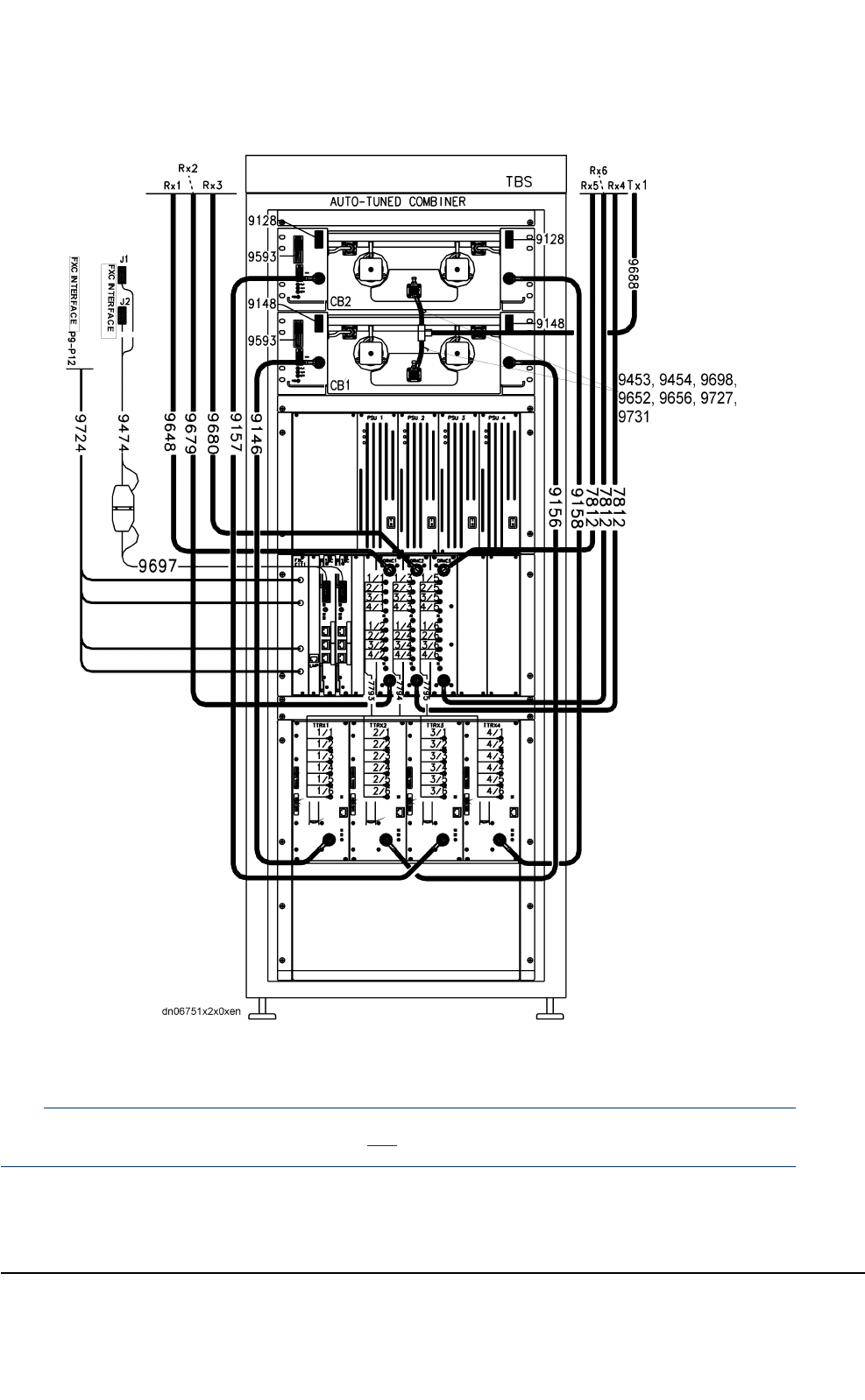

Table33:FrontcablecodesandroutingwithATC350,ATC380,ATC410,ATC450orATC800
CablecodeQuantityFromTo
91281)1setCombiner2RearCSRP16
91481)1setCombiner1RearCSRP16
95931setCSRP14/PWSRP9Combiner1and2system
connector
9727
(ATC350)
2Combiner1Combiner2
9652or9656
(ATC380)
2Combiner1Combiner2
9453or9454
(ATC410)
2Combiner1Combiner2
9698
(ATC450)
2Combiner1Combiner2
9731
(ATC800)
2Combiner1Combiner2
96881Combiner1TXant.conn.
91461TTRX1Combiner1
91561TTRX2Combiner1
91571TTRX3Combiner2
91581TTRX4Combiner2
96481RX1ant.conn.DRMC1/ANT1
96791RX2ant.conn.DRMC1/ANT2
96801RX3ant.conn.DRMC2/ANT1
78123RX4ant.conn.
RX5ant.conn.
RX6ant.conn.
DRMC2/ANT2
DRMC3/ANT1
DRMC3/ANT2
77931setDRMC1TTRX1–4/RX1&RX2
77941setDRMC2TTRX1–4/RX3&RX4
77951setDRMC3TTRX1–4/RX5&RX6
96971TBC1&2Cable9474
94741TBC
•toTBC1ifoneTBCisused
•tocable9697iftwoTBCs
areused
FXCIFJ1&J2
TETRASystemRelease5.5–6.5-InstallingtheTB3DN04153465-08-3en
ThisdocumentisthepropertyofCassidianandshouldnotbecopiedorcirculatedwithoutpermission.101(154)

Table33:FrontcablecodesandroutingwithATC350,ATC380,ATC410,ATC450orATC
800(cont’d.)
CablecodeQuantityFromTo
97232)1FXCAX5LMPPanel
97241setFXCE1/T1FCXIFP9–12
97251set
(optional)
FXCE1FXCIFP1–8
97713)2TBCi1/ETH1,ETH2TBCi(0)/ETH-1,ETH-2
97723)2TBCi2/ETH1,ETH2TBCi(1)/ETH-1,ETH-2
1)NotusedwithATC380andATC800.
2)Internalcable
3)Optional.Ethernetcables9771and9772areonlyusedwithTBCiforIPtransmission.
SeeSection8.3.
RefertoTB3HardwareDescription,dn04161675,formoreinformation.
8.1.2Cabinetrearcabling(4-carrierTB3withATC)
CAUTION
TakecarenottobendcombinerRFcablesunnecessarily.Checkalsothatthereisenoughroomfor
closingthecabinetdoor.ImproperhandlingmayaffectRFcharacteristicsanddamageconnectors.
CAUTION
Checkthecablelabelsandpossiblesitespecicinstructionstoensurecorrectcableconnections.
Refertopossiblesitespecicinstructionsforcabling.Thecablingandquantityofcablesmaydiffer
fromthefollowinggure.
DN04153465-08-3enTETRASystemRelease5.5–6.5-InstallingtheTB3
102(154)ThisdocumentisthepropertyofCassidianandshouldnotbecopiedorcirculatedwithoutpermission.
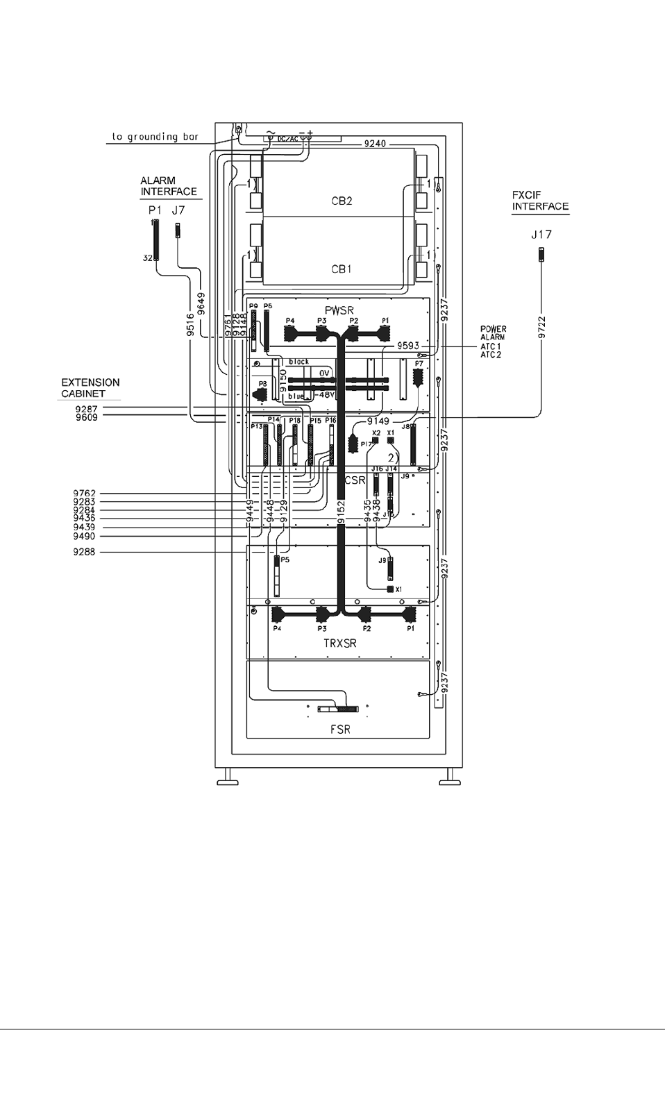
Figure44:Rearcabling
TETRASystemRelease5.5–6.5-InstallingtheTB3DN04153465-08-3en
ThisdocumentisthepropertyofCassidianandshouldnotbecopiedorcirculatedwithoutpermission.103(154)

Table34:Rearcablecodes
CablecodeQuantityFromTo
91521setPWSRP1...P4TRXSRP1...P4
91491PWSRP7CSRP17
91501PWSRP5CSRP151sthalf
95931setPWSRP9
CSRP14
ATC1/DDU1
ATC2/DDU2
96491PWSRP9ALIFJ7
94491PWSRP9FSR
94481CSRP131sthalfFSR
91291CSRP181stquarterTRXSRP51stquarter
91281setCSRP166th/8(tofront,seeTable10)
Combiner2
91481setCSRP165th/8(tofront,seeTable10)
Combiner1
94351CSRX2TRXSRX1
94381CSRJ16TRXSRJ9
97221CSRJ8Roof,FXCIFJ17
95161CSRP14,2ndhalfRoof,AlarmIFP1
92373SubrackgndRackgnd
97611CSRP15,7th/8Doorandrearpanel
alarmswitches
92401RackgndGndbaroncabinettop
Pwrwiring,
AC/DC
1CabinettopPWSRP8/LC-lter
RefertoTB3HardwareDescription,dn04161675,chapter12,formoreinformation.
DN04153465-08-3enTETRASystemRelease5.5–6.5-InstallingtheTB3
104(154)ThisdocumentisthepropertyofCassidianandshouldnotbecopiedorcirculatedwithoutpermission.
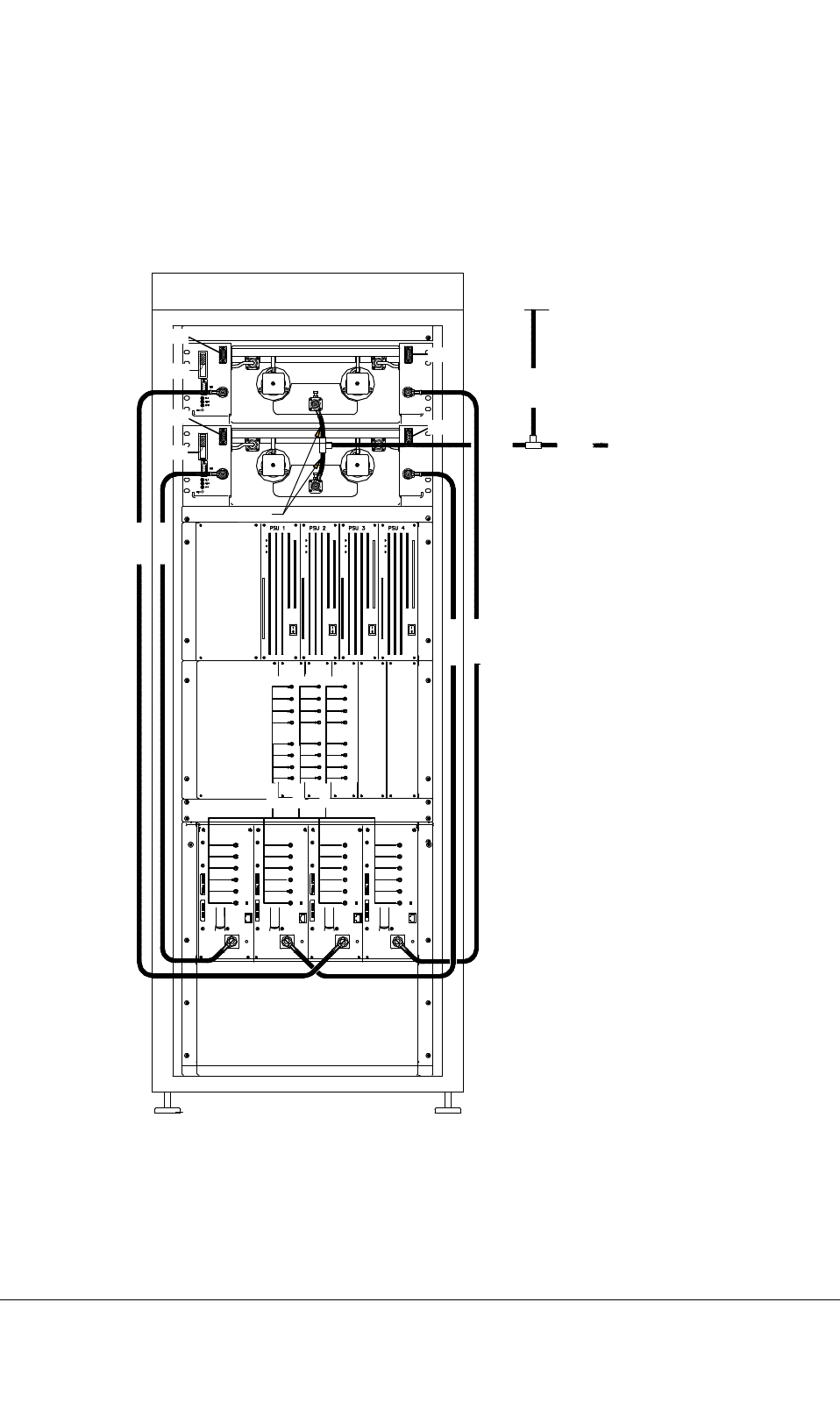
8.1.3Extensioncabinetfrontcabling
Refertopossiblesitespecicinstructionsforcabling.Thecablecodesandquantitymaydifferfromthe
followinggure.
TBS
DA 7629 AUTO-TUNED COMBINER
390-396 MHz
CB3
CB4
9146
9157
9158
9156
9652
9653
9688
9284
9283
9284
9609
9609
9283
1/2
2/2
3/2
4/2
Tx 1
9655 CB1/CB2
7795
7793
7794
dn06833x1x0xen
DDIV 1 DDIV 2 DDIV 3
1/1
2/1
3/1
4/1
1/4
2/4
3/4
4/4
1/3
2/3
3/3
4/3
1/6
2/6
3/6
4/6
1/5
2/5
3/5
4/5
TTRX1 TTRX2 TTRX3 TTRX4
1/1
1/2
1/3
1/4
1/6
1/5
2/1
2/2
2/3
2/4
2/6
2/5
3/1
3/2
3/3
3/4
3/6
3/5
4/1
4/2
4/3
4/4
4/6
4/5
Figure45:Frontcablingofextensioncabinet(examplefor390–396MHzrange)
TETRASystemRelease5.5–6.5-InstallingtheTB3DN04153465-08-3en
ThisdocumentisthepropertyofCassidianandshouldnotbecopiedorcirculatedwithoutpermission.105(154)

Note
Cables9283and9284arenotusedwithATC380andATC800.
Table35:Frontcablecodesandrouting,Extensioncabinet
CablecodeQuantityFromTo
91461TTRX1Combiner3
91561TTRX2Combiner3
91571TTRX3Combiner4
91581TTRX4Combiner4
77931setDDIV1TTRX1–4/RX1&RX2
77941setDDIV2TTRX1–4/RX3&RX4
77951setDDIV3TTRX1–4/RX5&RX6
RefertoTB3HardwareDescription,dn04161675,formoreinformation.
DN04153465-08-3enTETRASystemRelease5.5–6.5-InstallingtheTB3
106(154)ThisdocumentisthepropertyofCassidianandshouldnotbecopiedorcirculatedwithoutpermission.

8.1.4Extensioncabinetrearcabling
CAUTION
WhenwiringtheTB3backplane,itisadvicedtotakespecialcarethattheconnectorsarepluggedin
therightway.Formoreinformation,seeAppendixAinthisdocumentandChapterInternalcablingin
TBSHardwareDescription,dn04161675.
Refertopossiblesite-speciccablinginstructions.Thecablesmaydifferfromthefollowinggure.
TETRASystemRelease5.5–6.5-InstallingtheTB3DN04153465-08-3en
ThisdocumentisthepropertyofCassidianandshouldnotbecopiedorcirculatedwithoutpermission.107(154)
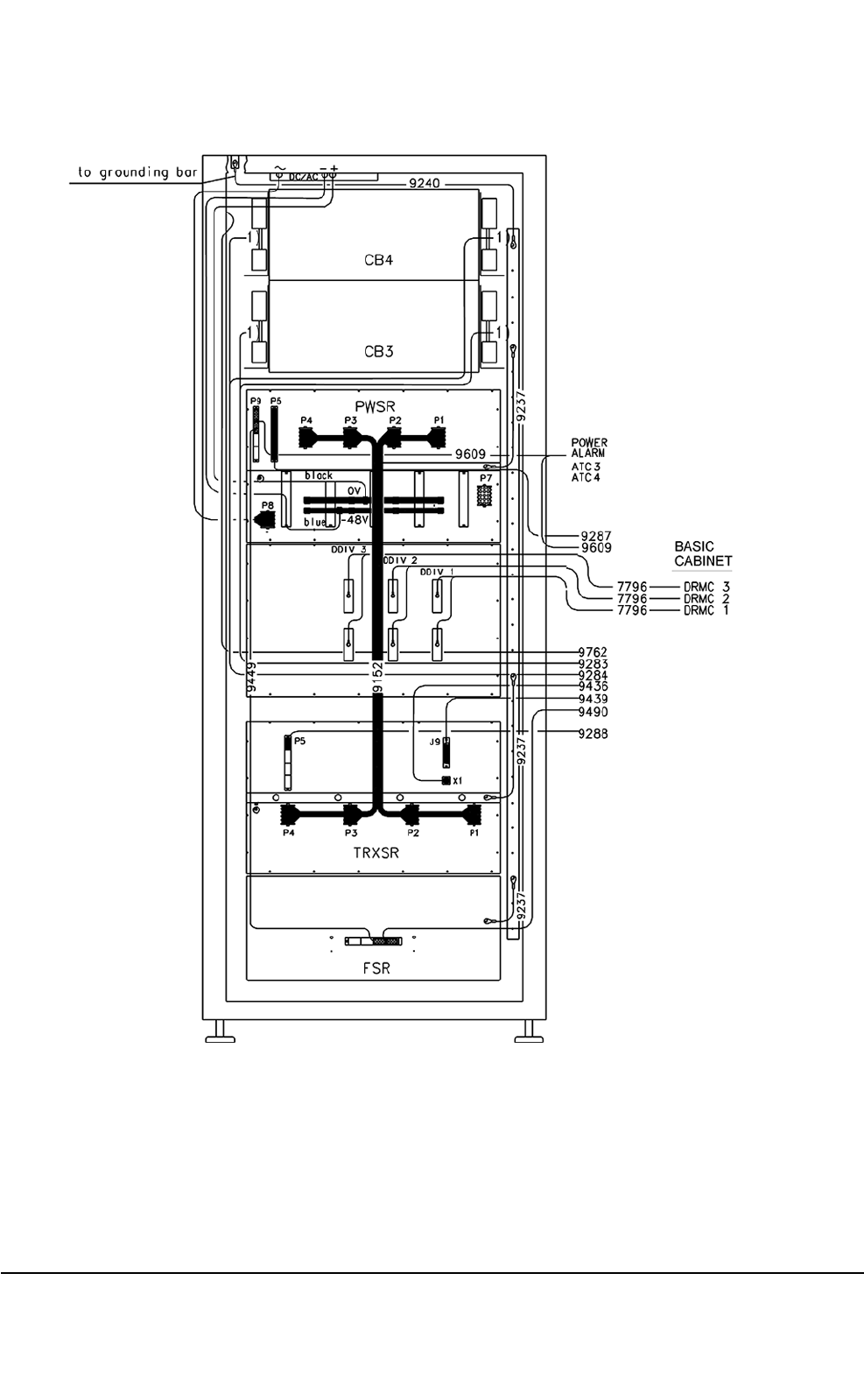
Figure46:Extensioncabinetrearcabling
DN04153465-08-3enTETRASystemRelease5.5–6.5-InstallingtheTB3
108(154)ThisdocumentisthepropertyofCassidianandshouldnotbecopiedorcirculatedwithoutpermission.

Table36:RearcablecodesforExtensioncabinet
CablecodeQuantityFromTo
91521setPWSRP1...P4TRXSRP1...P4
94491PWSRP9FSR
92372Subrackgnd.Rackgnd.
92401Rackgnd.Gndbaroncabinettop
Pwr.wiring,
AC/DC
CabinettopPWSRP8/LC-lter
RefertoTB3HardwareDescription,dn04161675,formoreinformation.SeealsoAppendixA.
Table37:CablesbetweenBasicandExtensioncabinetsinATCcases
Cable
code
QuantityFrom(Ext.cabinet)To(Basiccabinet)
96091setATC3&4/PWSRP9
1st/4
CSRP142nd/4
92871PWSRP5CSRP153rd/4
97621DooralarmswitchCSRP158th/8
92831)1setCombiner3CSRP167th/8
92841)1setCombiner4CSRP168th/8
94361TRXSRX1CSRX1
94391TRXSRJ9CSRJ14
94901FSRFan41st/4CSRP132nd/2
92881TRXSRP51st/4CSRP182nd/4
77963DDIV1
DDIV2
DDIV3
DRMC1/AUX1,AUX2
DRMC2/AUX1,AUX2
DRMC3/AUX1,AUX2
TXRF-cablingCombiner3&4Combiner1&2
1)NotusedwithATC380andATC800.
RefertoTB3HardwareDescription,dn04161675,formoreinformation.SeealsoAppendixA.
8.1.5Cablingforalternativecavitycombinertypes
Cablingforthealternativecombinertypesisshowninthefollowinggures.
TETRASystemRelease5.5–6.5-InstallingtheTB3DN04153465-08-3en
ThisdocumentisthepropertyofCassidianandshouldnotbecopiedorcirculatedwithoutpermission.109(154)
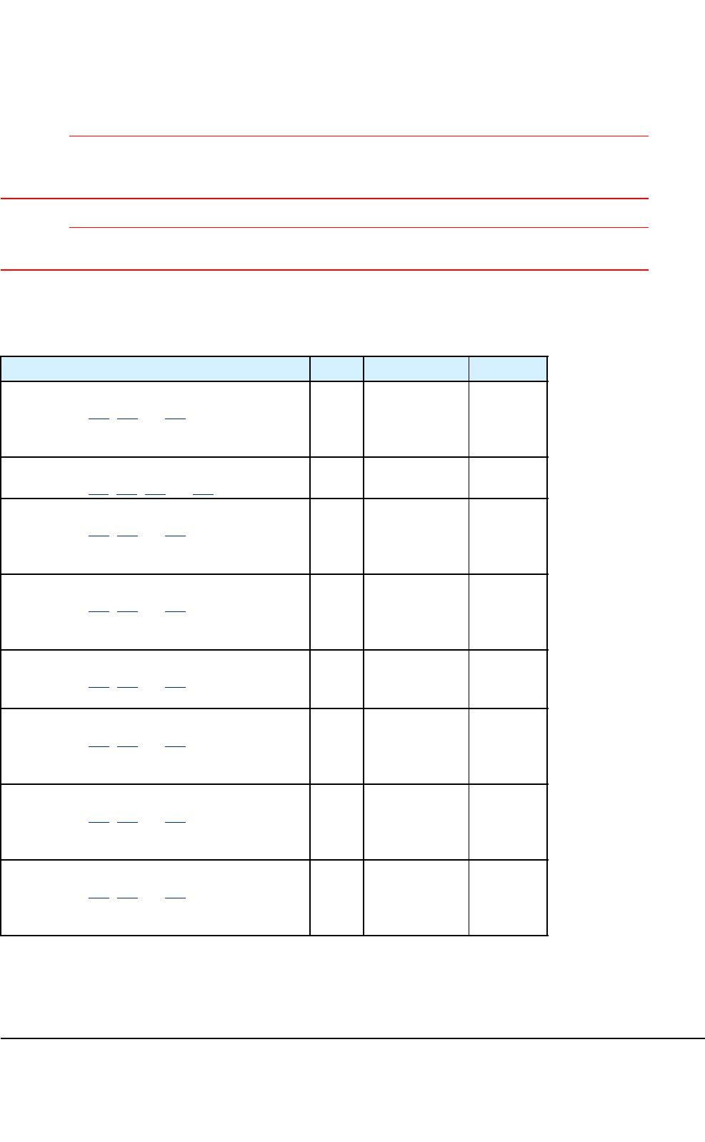
CAUTION
TakecarenottobendcombinerRFcablesunnecessarily.Checkalsothatthereisenoughroomfor
closingthecabinetdoor.ImproperhandlingmayaffectRFcharacteristicsanddamageconnectors.
CAUTION
Checkthecablelabelsandpossiblesitespecicinstructionstoensurecorrectcableconnections.
RefertothedocumentTB3HardwareDescription,dn04161675,formoreinformation.
Table38:Cavitycombinertypes,sub-bandsandcables
CombinertypeIDSub-bandCables
ATC350
SeeFigures47,48and49
7971360–370MHzA=9727
B=9728
C=9729
D=3730
Cavitycombiner380
SeeFigures50,51,52and53
7004390-400MHzS=7096
L=7097
ATC380
SeeFigures47,48and49
7629390-396MHzA=9652
B=9653
C=9654
D=9655
ATC380
SeeFigures47,48and49
7629395-400MHzA=9656
B=9657
C=9658
D=9659
Cavitycombiner410
SeeFigures54,55and56
7065420-430MHzA=7102
B=7103
C=7104
ATC410
SeeFigures47,48and49
7141420-426MHzA=9453
B=9457
C=9461
D=9465
ATC410
SeeFigures47,48and49
7141425-431MHzA=9454
B=9458
C=9462
D=9466
ATC450
SeeFigures47,48and49
7835460-466MHzA=9698
B=9699
C=9700
D=9701
DN04153465-08-3enTETRASystemRelease5.5–6.5-InstallingtheTB3
110(154)ThisdocumentisthepropertyofCassidianandshouldnotbecopiedorcirculatedwithoutpermission.

Table38:Cavitycombinertypes,sub-bandsandcables(cont’d.)
CombinertypeIDSub-bandCables
ATC800(300kHz)
SeeFigures47,48and49
7996851–865MHzA=9731
B=9732
C=9733
D=9734
ATC800(300kHz)
SeeFigures47,48and49
7996855–869MHzA=9731
B=9736
C=9737
D=9738
ATC800(150kHz)
SeeFigures47,48and49
7997851–865MHzA=9731
B=9732
C=9733
D=9734
ATC800(150kHz)
SeeFigures47,48and49
7997855–869MHzA=9731
B=9736
C=9737
D=9738
Note
ATC800A-cable9731ismatchedforthewhole851to869MHzbandwidth.
TETRASystemRelease5.5–6.5-InstallingtheTB3DN04153465-08-3en
ThisdocumentisthepropertyofCassidianandshouldnotbecopiedorcirculatedwithoutpermission.111(154)
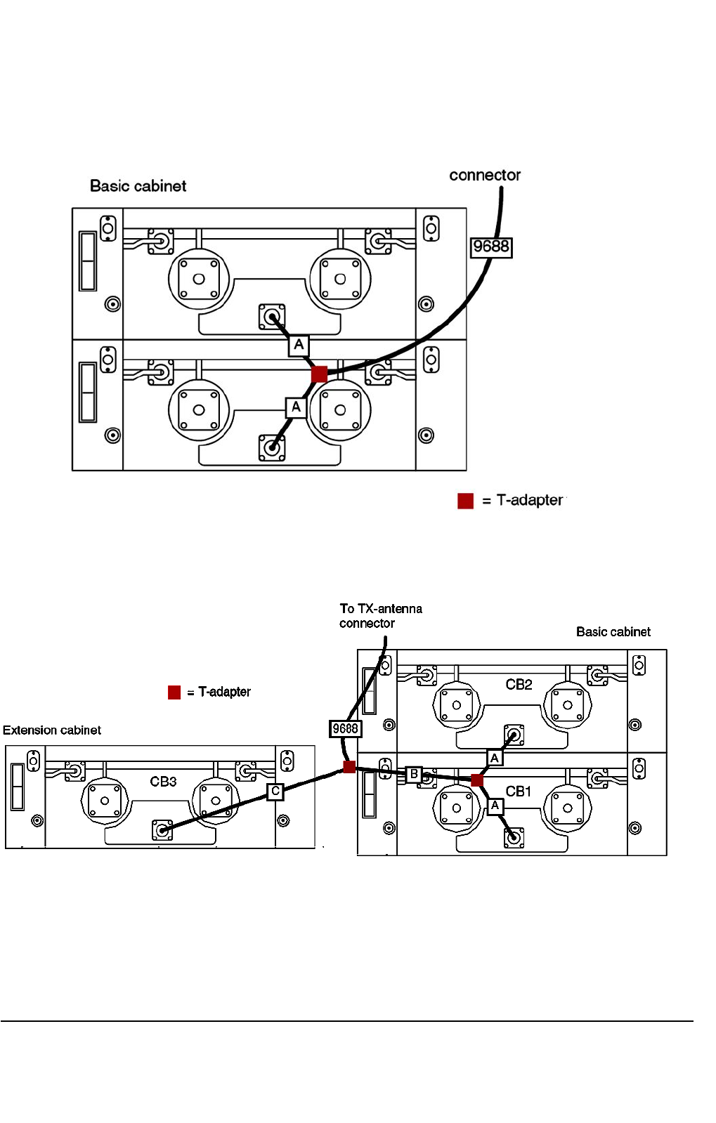
8.1.5.1Auto-tunedcavitycombiners
Figure47:RFcablingbetweenAuto-tunedcavitycombinersandTX-antennaconnector:4-carrier
conguration
Figure48:RFcablingbetweenAuto-tunedcavitycombinersandTX-antennaconnector:6-carrier
conguration
DN04153465-08-3enTETRASystemRelease5.5–6.5-InstallingtheTB3
112(154)ThisdocumentisthepropertyofCassidianandshouldnotbecopiedorcirculatedwithoutpermission.
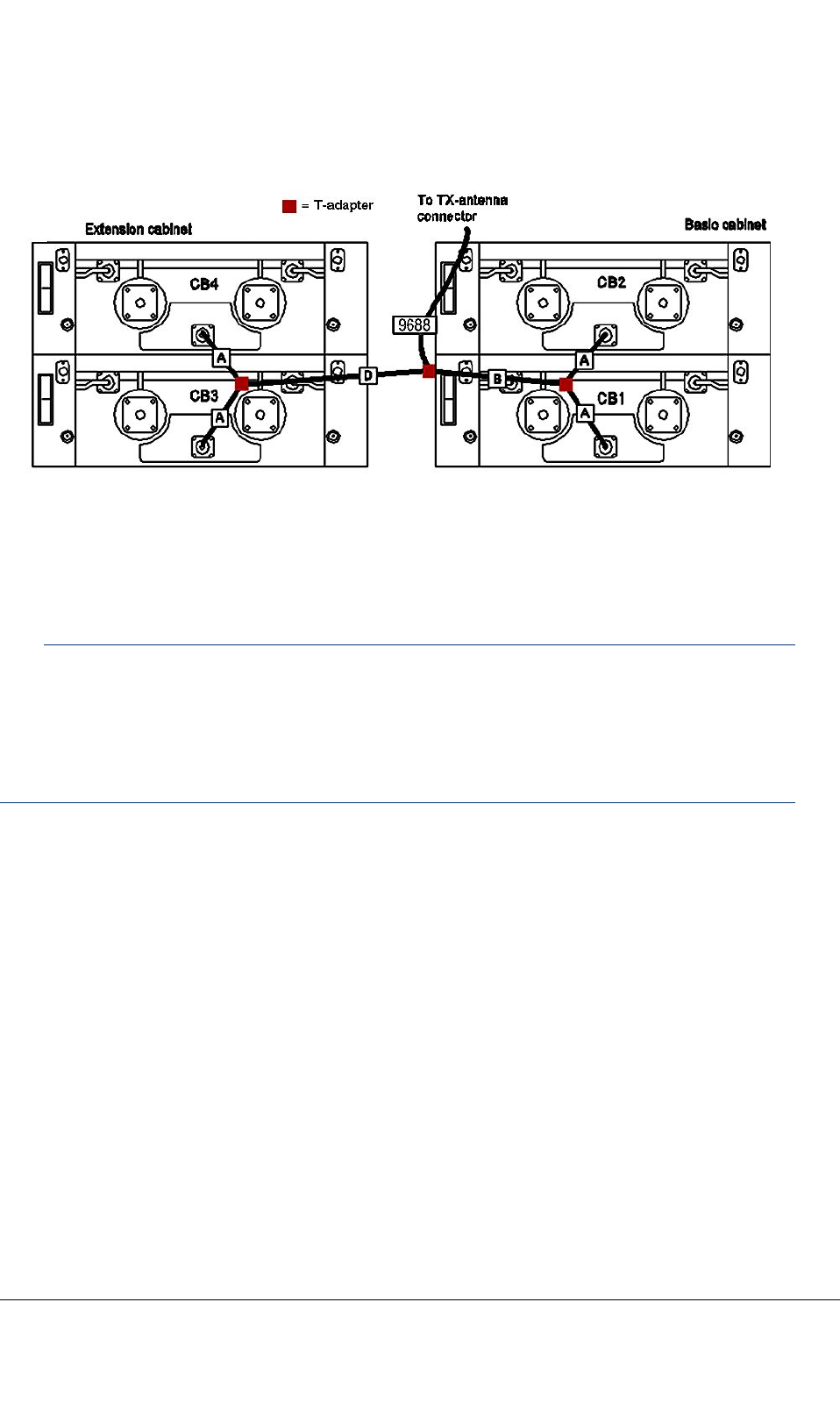
Figure49:RFcablingbetweenAuto-tunedcavitycombinersandTX-antennaconnector:8-carrier
conguration
8.1.5.2380MHzmanuallytunedcavitycombiner(DA7004)
Note
Whenusing380MHzmanualcombiners,thecombinerclosesttotheantennashouldusethelowest
frequencies,thenextnearestcombinershouldusethesecondlowestfrequencies,andsoon.Within
eachcombiner,thereisnosignicanceinwhichcavityinputthelowerofthetwofrequenciesis.The
frequencyorderisespeciallyimportantfor5to8channelsystems,whereitmakesabigdifferenceon
insertionlossandoutputreturnloss.
TETRASystemRelease5.5–6.5-InstallingtheTB3DN04153465-08-3en
ThisdocumentisthepropertyofCassidianandshouldnotbecopiedorcirculatedwithoutpermission.113(154)
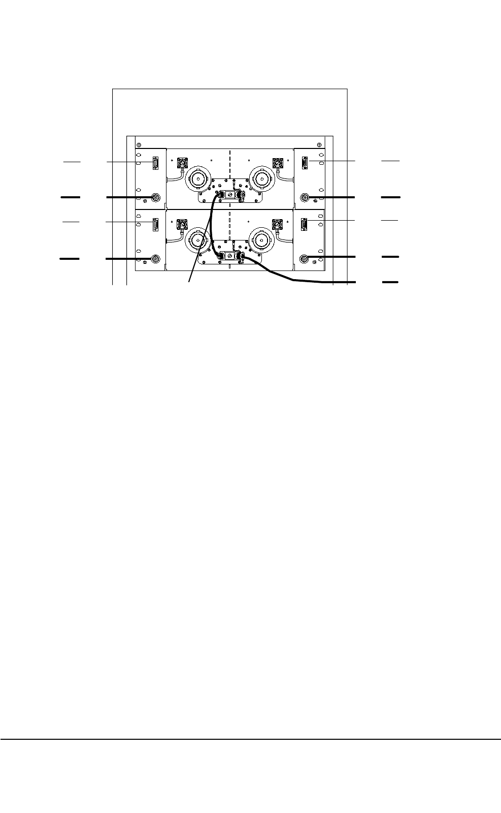
TBS
DA 7004 CAVITY COMBINER
7096
CB1
CB2
9148
9156
9128
9158
9128
9157
9148
9146
9688
Figure50:380MHzmanuallytunedcavitycombinercables
DN04153465-08-3enTETRASystemRelease5.5–6.5-InstallingtheTB3
114(154)ThisdocumentisthepropertyofCassidianandshouldnotbecopiedorcirculatedwithoutpermission.
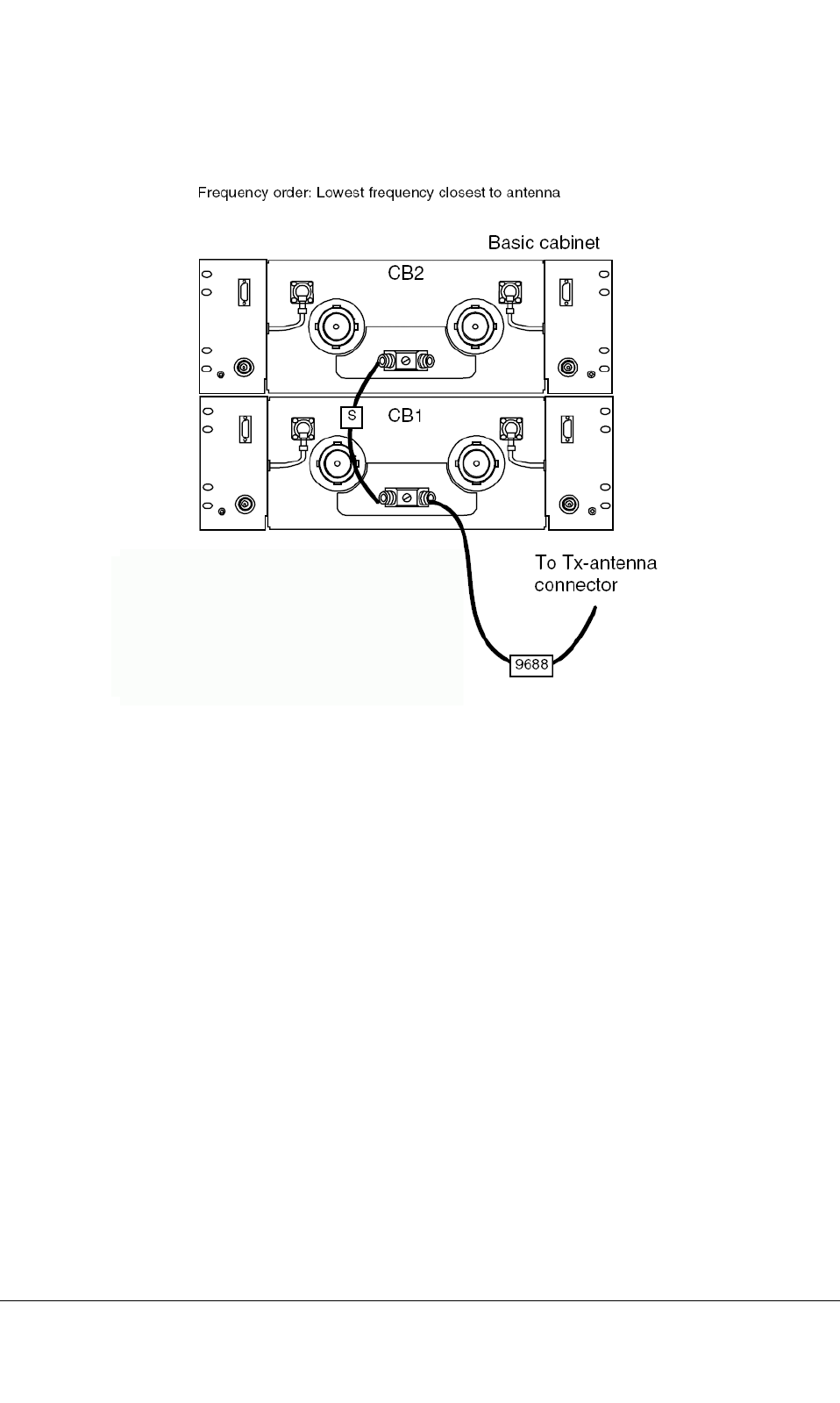
Figure51:RFcablingbetweenmanuallytunedCB380andTX-antennaconnector:4-carrier
conguration
TETRASystemRelease5.5–6.5-InstallingtheTB3DN04153465-08-3en
ThisdocumentisthepropertyofCassidianandshouldnotbecopiedorcirculatedwithoutpermission.115(154)
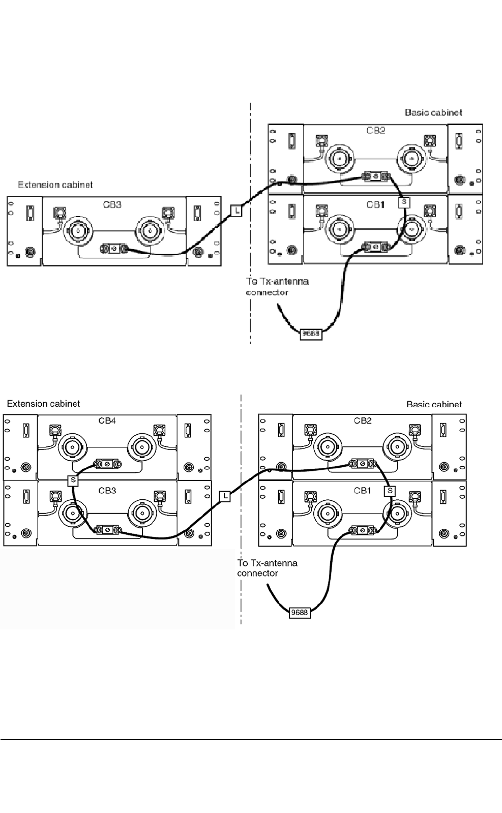
Figure52:RFcablingbetweenmanuallytunedCB380andTX-antennaconnector:6-carrier
conguration
Figure53:RFcablingbetweenmanuallytunedCB380andTX-antennaconnector:8-carrier
conguration
DN04153465-08-3enTETRASystemRelease5.5–6.5-InstallingtheTB3
116(154)ThisdocumentisthepropertyofCassidianandshouldnotbecopiedorcirculatedwithoutpermission.
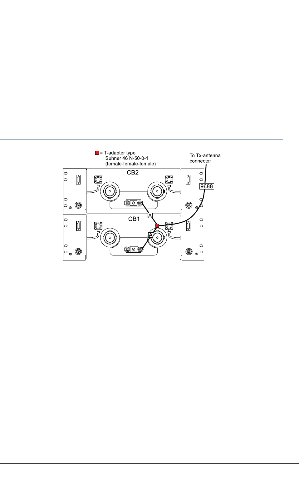
8.1.5.3410MHzmanuallytunedcavitycombiner(DA7065)
Note
In2and4chcongurationsthefrequencyorderisfree.
In6and8chcongurationsfrequenciesofCBs3and4(orCBsnearesttoantenna)aretobehigher
thanfrequenciesofCBs1and2(orCBsfarthesttoantenna).
CablesBandCcanbereversedrespectingthefrequencyorder:CombinersconnectedtocableC
shallhavehigherfrequenciesthatcombinersconnectedtocableB.
CB2
CB1
AA
= T-adaptertype
Suhner46N-50-0-1
(female-female-female)
To Tx-antenna
connector
9688
A
Figure54:RFcablingbetweenmanuallytunedCB410andTX-antennaconnector:4-carrier
conguration
TETRASystemRelease5.5–6.5-InstallingtheTB3DN04153465-08-3en
ThisdocumentisthepropertyofCassidianandshouldnotbecopiedorcirculatedwithoutpermission.117(154)
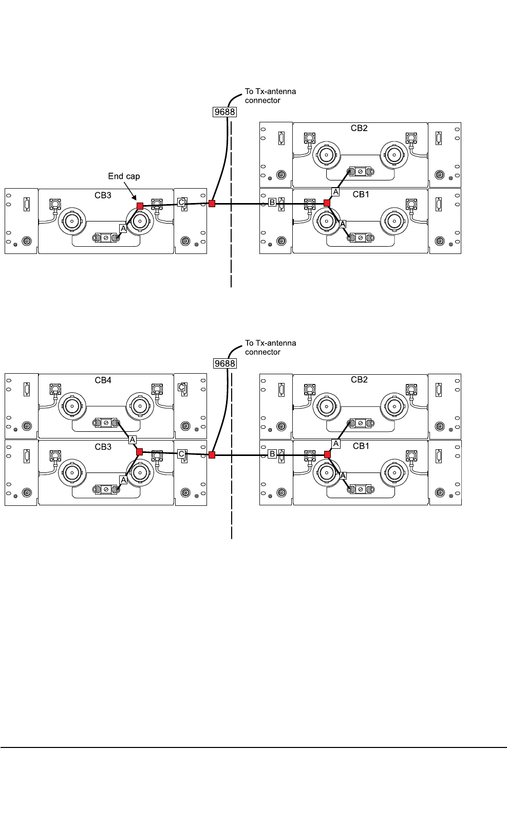
CB2
CB1
AA
A
To Tx-antenna
connector
CB3
9688
Endcap
BC
A
Figure55:RFcablingbetweenmanuallytunedCB410andTX-antennaconnector:6-carrier
conguration
CB2
CB1
AA
A
To Tx-antenna
connector
9688
B
CB3
C
A
CB4
C
A
Figure56:RFcablingbetweenmanuallytunedCB410andTX-antennaconnector:8-carrier
conguration
DN04153465-08-3enTETRASystemRelease5.5–6.5-InstallingtheTB3
118(154)ThisdocumentisthepropertyofCassidianandshouldnotbecopiedorcirculatedwithoutpermission.

8.2Widebandcombiner(WBC)anddualduplexer(DDU)
CAUTION
TakecarenottobendcombinerRFcablesunnecessarily.Checkalsothatthereisenoughroomfor
closingthecabinetdoor.ImproperhandlingmayaffectRFcharacteristicsanddamageconnectors.
CAUTION
Checkthecablelabelsandpossiblesitespecicinstructionstoensurecorrectcableconnections.
8.2.1Cabinetfrontcabling(2-carrierTB3withWBC)
Refertopossiblesite-specicinstructionsforcabling.Thecablecodesandquantitymaydifferfrom
thefollowinggures.
TETRASystemRelease5.5–6.5-InstallingtheTB3DN04153465-08-3en
ThisdocumentisthepropertyofCassidianandshouldnotbecopiedorcirculatedwithoutpermission.119(154)
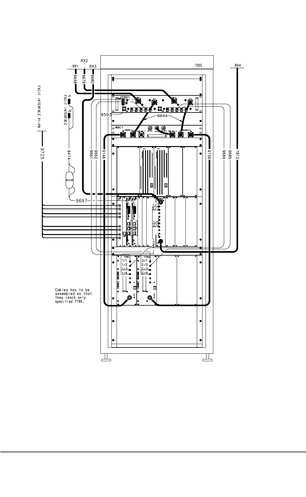
dn06857x1x0xen
Figure57:Cabinetfrontcablingfor2-carrierTB3withWBC(FXCE1)
DN04153465-08-3enTETRASystemRelease5.5–6.5-InstallingtheTB3
120(154)ThisdocumentisthepropertyofCassidianandshouldnotbecopiedorcirculatedwithoutpermission.
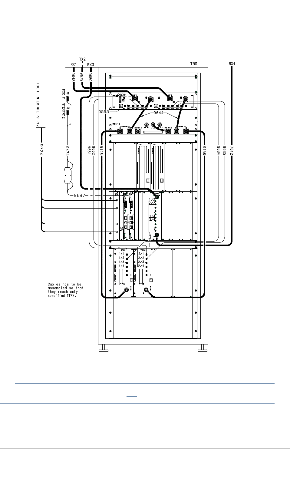

Table39:FrontcablecodesandroutingwithWBC
CablecodeQuantityFromTo
91461TTRX1/TXWBC1/Isolator1IN
91561TTRX2/TXWBC1/Isolator2IN
96442WBC1/Isolator1
OUT
WBC1/Isolator2
OUT
DDU1/TX1
DDU1/TX2
95931setRearCSRP14/
PWSRP9
DDU1and2system
connector
96481RX1ant.conn.DDU1/ANT1
96791RX2ant.conn.DDU1/ANT2
96801RX3ant.conn.DRMC2/ANT1
78121RX4ant.conn.DRMC2/ANT2
96611DDU1/RX1/1TTRX1/RX1
96621DDU1/RX2/1TTRX2/RX1
96841DDU1/RX1/2TTRX1/RX2
96851DDU1/RX2/2TTRX2/RX2
96971TBC1&2Cable9474
94741TBC
•toTBC1ifone
TBCisused
•tocable9697
iftwoTBCs
areused
FXCIFJ1&J2
77941setDRMC2TTRX1–2/RX3&RX4
97231)1FXCAX5LMPPanel
97241setFXCE1/T1FCXIFP9–12
97251set
(optional)
FXCE1FXCIFP1–8
97712)2TBCi1/ETH1,ETH2TBCi(0)/ETH-1,ETH-2
97722)2TBCi2/ETH1,ETH2TBCi(1)/ETH-1,ETH-2
1)Internalcable
2)Optional.Ethernetcables9771and9772areonlyusedwithTBCifor
IPtransmission.SeeSection8.3.
DN04153465-08-3enTETRASystemRelease5.5–6.5-InstallingtheTB3
122(154)ThisdocumentisthepropertyofCassidianandshouldnotbecopiedorcirculatedwithoutpermission.

RefertoTB3HardwareDescription,dn04161675,formoreinformation.
8.2.2Rearcabling(WBC)
Refertopossiblesite-specicinstructionsforcabling.Thecablecodesandquantitymaydifferfromthe
followinggure.
TETRASystemRelease5.5–6.5-InstallingtheTB3DN04153465-08-3en
ThisdocumentisthepropertyofCassidianandshouldnotbecopiedorcirculatedwithoutpermission.123(154)
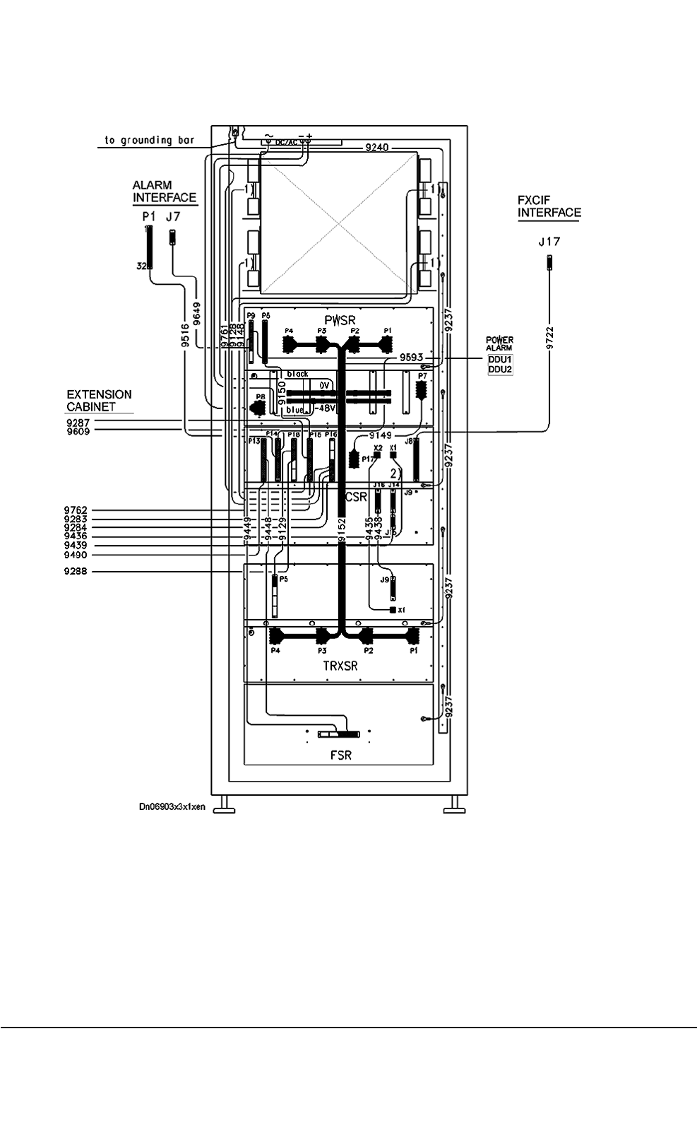
Figure59:Rearcabling(WBC)
DN04153465-08-3enTETRASystemRelease5.5–6.5-InstallingtheTB3
124(154)ThisdocumentisthepropertyofCassidianandshouldnotbecopiedorcirculatedwithoutpermission.

Table40:Rearcablecodes
CablecodeQuantityFromTo
91521setPWSRP1...P4TRXSRP1...P4
91491PWSRP7CSRP17
91501PWSRP5CSRP151sthalf
95931setPWSRP9
CSRP14
DDU1
DDU2
96491PWSRP93rd/4ALIFJ7
94491PWSRP92nd/4FSR2nd/4
94481CSRP131sthalfFSR1st/4
91291CSRP181stquarterTRXSRP51stquarter
91281setCSRP166th/8(notinuse)
91481setCSRP165th/8(notinuse)
94351CSRX2TRXSRX1
94381CSRJ16TRXSRJ9
97221CSRJ8Roof,FXCIFJ17
95161CSRP14,2ndhalfRoof,AlarmIFP1
92374SubrackgndRackgnd
97611CSRP15,7th/8Dooralarmswitch
92401RackgndGndbaroncabinettop
Pwr.wiring,
AC/DC
1CabinettopPWSRP8/LC-lter
RefertoTETRASystem:TB3HardwareDescription,dn04161675formoreinformationandforthe
extensioncabinetcombinercabling.
8.2.3Extensioncabinetfrontcabling(WBC)
Refertopossiblesite-specicinstructionsforcabling.Thecablecodesandquantitymaydifferfromthe
followinggure.
TETRASystemRelease5.5–6.5-InstallingtheTB3DN04153465-08-3en
ThisdocumentisthepropertyofCassidianandshouldnotbecopiedorcirculatedwithoutpermission.125(154)
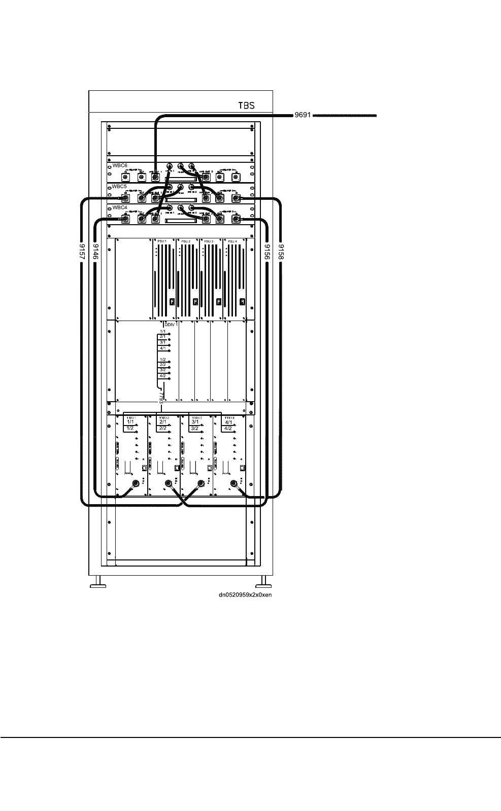
WBC6
WBC5
WBC4
9157
9146
9156
9158
9691
DDIV1
1/1
2/1
3/1
4/1
1/2
2/2
3/2
4/2
PSU1 PSU2 PSU3 PSU4
7793
1/1
1/2
2/1
2/2
3/1
3/2
4/1
4/2
dn0520959x2x0xen
Figure60:Extensioncabinetfrontcabling(WBC),oneDDIV
DN04153465-08-3enTETRASystemRelease5.5–6.5-InstallingtheTB3
126(154)ThisdocumentisthepropertyofCassidianandshouldnotbecopiedorcirculatedwithoutpermission.

Table41:Frontcablecodes,Extensioncabinet(WBC)
CablecodeQuantityFromTo
91461TTRX1/TXWBC4/Isolator1IN
91561TTRX2/TXWBC4/Isolator2IN
91571TTRX3/TXWBC5/Isolator1IN
91581TTRX4/TXWBC5/Isolator2IN
77931setDDIV1TTRX1–4/RX1&RX2
96911WBC6/HYBOUT1DDU1/TX2
8.2.4Extensioncabinetrearcabling(WBC)
CAUTION
WhenwiringtheTB3backplane,itisadvicedtotakespecialcarethattheconnectorsarepluggedin
therightway.Formoreinformation,seeAppendixA.
Refertopossiblesite-specicinstructionsforcabling.
Thecablecodesandquantitymaydifferfromthefollowinggure.
TETRASystemRelease5.5–6.5-InstallingtheTB3DN04153465-08-3en
ThisdocumentisthepropertyofCassidianandshouldnotbecopiedorcirculatedwithoutpermission.127(154)
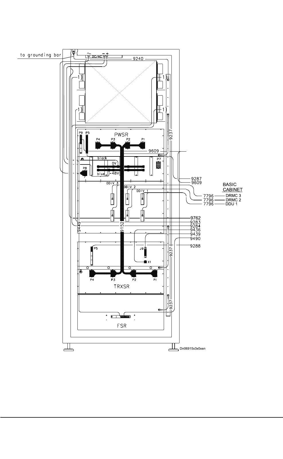
Dn06915x3x0xen
DDU1
DRMC2
DRMC3
BASIC
CABINET
9762
Figure61:Extensioncabinetrearcabling(WBC),threeDDIVs
DN04153465-08-3enTETRASystemRelease5.5–6.5-InstallingtheTB3
128(154)ThisdocumentisthepropertyofCassidianandshouldnotbecopiedorcirculatedwithoutpermission.

Table42:Rearcablecodes,Extensioncabinet(WBC)
CablecodeQuantityFromTo
91521setPWSRP1...P4TRXSRP1...P4
94491PWSRP9FSR
92373SubrackgndRackgnd
92401RackgndGndbaroncabinettop
Pwr.wiring,
AC/DC
CabinettopPWSRP8/LC-lter
ThefollowingtableshowsthecablesbetweenextensionandbasiccabinetsinWBCcases.
Table43:CablesbetweenExtensionandBasiccabinetsinWBCcases
Cable
code
QuantityFrom
(Extension
cabinet)
To(Basic
cabinet)
Note!
96091set(ATC3&4/
PWSRP9)
CSRP142nd/4Notin
use
92871PWSRP5CSRP153rd/4
97621Dooralarm
switch
CSRP158th/8
92831set(Combiner3)CSRP167th/8Notin
use
92841set(Combiner4)CSRP168th/8Notin
use
94361TRXSRX1CSRX1
94391TRXSRJ9CSRJ14
94901FSRFan41st/4CSRP132nd/2
92881TRXSRP5CSRP182nd/4
96911WBC6/
HYBOUT1
DDU1/TX2
77961setDDIV1
DDIV1
DDIV2
DDIV2
DDIV3
DDIV3
DDU1/AUX1
DDU1/AUX2
DRMC2/AUX1
DRMC2/AUX2
DRMC3/AUX1
DRMC3/AUX2
RefertoTB3HardwareDescription,dn04161675,formoreinformation.SeealsoAppendixA.
TETRASystemRelease5.5–6.5-InstallingtheTB3DN04153465-08-3en
ThisdocumentisthepropertyofCassidianandshouldnotbecopiedorcirculatedwithoutpermission.129(154)

8.2.5Cablingforalternativecongurations
8.2.5.1Radiofrequency(RF)cabling
ConnecttheRFcablesaccordingtoconguration.Seethefollowinggures.
CAUTION
Installthecablescarefully.Checkespeciallythattheextensioncabinetcableswillnotbesharplybent
neartheconnectorswhenthecabinetdoorsareclosed.Improperhandlingwilldamagethecables.
DN04153465-08-3enTETRASystemRelease5.5–6.5-InstallingtheTB3
130(154)ThisdocumentisthepropertyofCassidianandshouldnotbecopiedorcirculatedwithoutpermission.
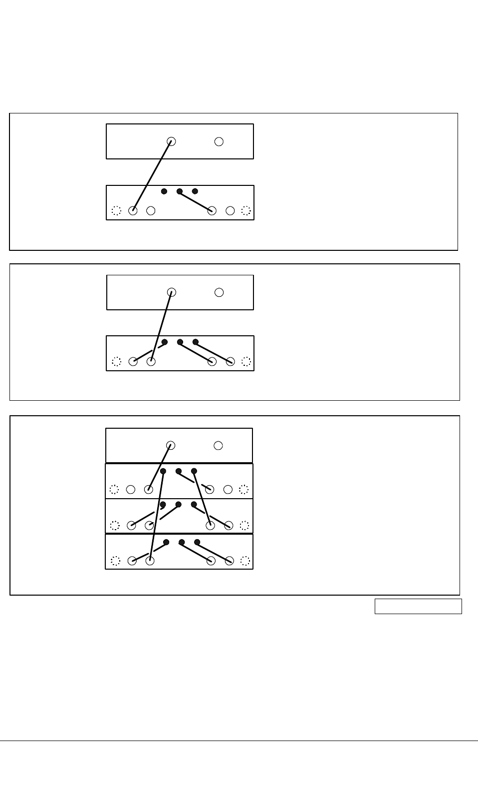
2 channels:
3-4 channels:
1 channel:
TX1 TX2
ISOLATOR1
OUT
ISOLATOR2
OUT
HYB
OUT1
HYB
OUT2
TX1 TX2
DDU1
WBC
ONE ANTENNA
ISOLATOR1
OUT
ISOLATOR2
OUT
HYB
OUT1
HYB
OUT2
DDU1
WBC1
WBC2
WBC3
dn02194298x2x0xen
ISOLATOR1
OUT
ISOLATOR2
OUT
HYB
OUT1
HYB
OUT2
TX1 TX2
DDU1
WBC
By-pass
WBC 2:1
WBC 4:1
Figure62:WBCcongurations,oneantenna
TETRASystemRelease5.5–6.5-InstallingtheTB3DN04153465-08-3en
ThisdocumentisthepropertyofCassidianandshouldnotbecopiedorcirculatedwithoutpermission.131(154)
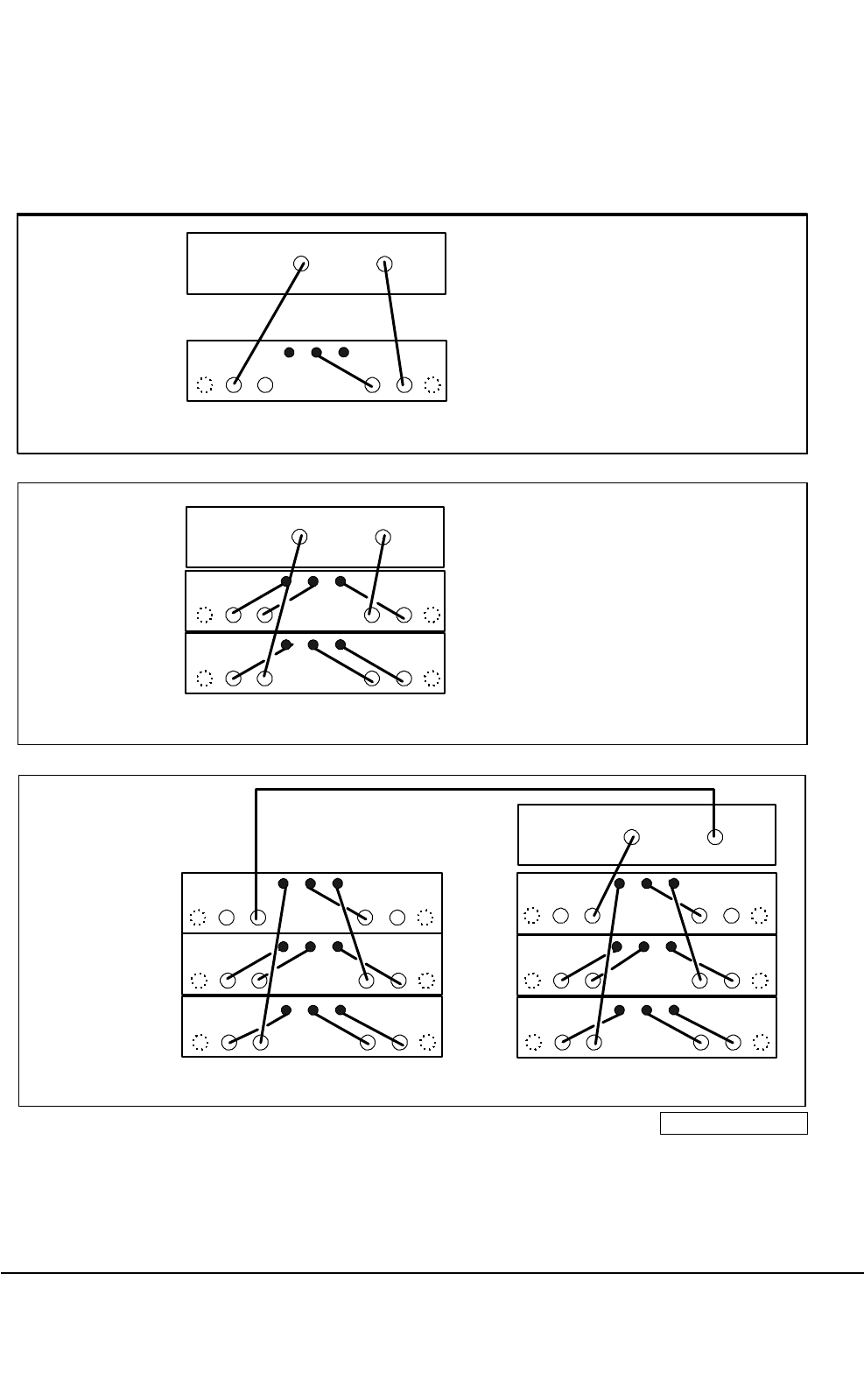
1-2 channels:
3-4 channels:
5-8 channels:
TX1 TX2
ISOLATOR1
OUT
ISOLATOR2
OUT
HYB
OUT1
HYB
OUT2
TX1 TX2
DDU1
WBC
HYB
LOAD
2 ANTENNAS
ISOLATOR1
OUT
ISOLATOR2
OUT
HYB
OUT1
HYB
OUT2
WBC2
WBC1
DDU1
ISOLATOR1
OUT
ISOLATOR2
OUT
HYB
OUT1
HYB
OUT2
WBC4
WBC5
WBC6
TX1 TX2
WBC1
WBC2
WBC3
DDU1
dn02194165x2x0xen
By-pass
WBC 2:1
WBC 4:1
Figure63:WBCcongurations,2antennas
DN04153465-08-3enTETRASystemRelease5.5–6.5-InstallingtheTB3
132(154)ThisdocumentisthepropertyofCassidianandshouldnotbecopiedorcirculatedwithoutpermission.
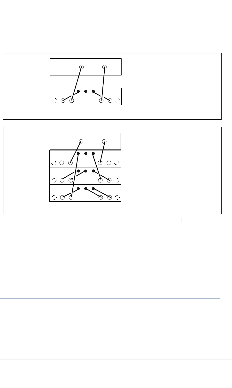
1-2 channels:
3-4 channels: TX1 TX2
ISOLATOR1
OUT
ISOLATOR2
OUT
HYB
OUT1
HYB
OUT2
TX1 TX2
DDU1
WBC
ROAD, 2 ANTENNAS
ISOLATOR1
OUT
ISOLATOR2
OUT
HYB
OUT1
HYB
OUT2
DDU1
WBC1
WBC2
WBC3
dn02194441x2x0xen
WBC 2:1
WBC 4:1
Figure64:WBCcongurations,road
8.3IPtransmissioncabling
IPtransmissionwiththeTBCiisoptional.ItisanalternativetoE1transmission.
Note
TheTB3canonlybeusedforonetypeoftransmissionatatime.
InthecaseofIPtransmission,ethernetcables9771and9772areused.Twoorfourcablesare
required,dependingonwhetheraredundantTBCiisused.Thecablesneedtobeorderedseparately
withthefollowingproductcodes:
TETRASystemRelease5.5–6.5-InstallingtheTB3DN04153465-08-3en
ThisdocumentisthepropertyofCassidianandshouldnotbecopiedorcirculatedwithoutpermission.133(154)

•DA9771:IPcablesforTBCi
•DA9772:IPcablesfortheredundantTBCi
Figure65showstheoptionalIPtransmissioncablingconnectionsbetweentheTBCicardstothe
basic-cabinettop-plateinterfaces.
DN04153465-08-3enTETRASystemRelease5.5–6.5-InstallingtheTB3
134(154)ThisdocumentisthepropertyofCassidianandshouldnotbecopiedorcirculatedwithoutpermission.
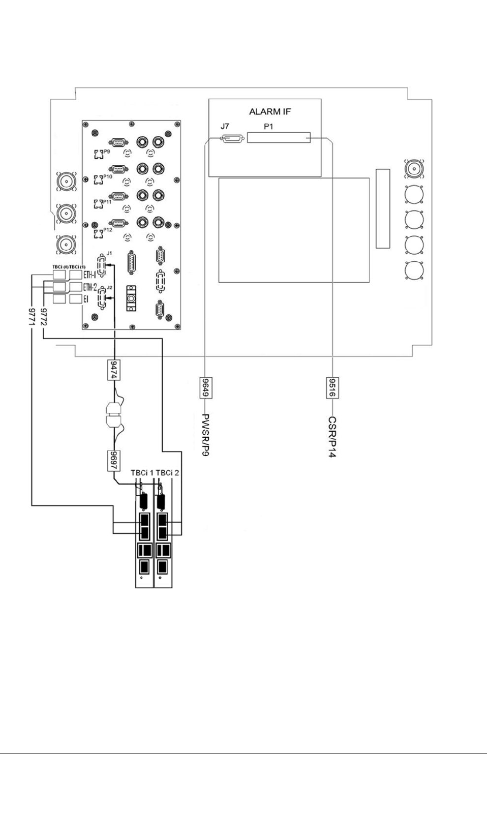
Figure65:CablingbetweenTBCiandbasic-cabinettop-plateinterfaces(IPtransmission)
Furtherinformation
ForinformationonhowtoreplaceTBC-UwiththeTBCiplug-inunit,seeMaintenanceofTETRA
BaseStations,dn00132139.
TETRASystemRelease5.5–6.5-InstallingtheTB3DN04153465-08-3en
ThisdocumentisthepropertyofCassidianandshouldnotbecopiedorcirculatedwithoutpermission.135(154)

PAGEINTENTIONALLYLEFTBLANK
DN04153465-08-3enTETRASystemRelease5.5–6.5-InstallingtheTB3
136(154)ThisdocumentisthepropertyofCassidianandshouldnotbecopiedorcirculatedwithoutpermission.

CHAPTER
9
Completingtheinstallation
ThischapterdetailsthecompletiontasksrelatedtotheinstallationoftheTB3.
Whentheinstallationiscompleted,theequipmentandthesitemustbebroughtinasuitablestatefor
commissioningandthepaperworkmustbecompletedandled.
WhencommissioningtheTB3,thesystemwillbepowereduptomakesurethattheTB3isinasuitable
congurationforthecommissioningprocedure.
9.1Power-uptest
Note
Thepower-uptestshouldbemadeonlyincasethattheinstallationisimmediatelyfollowedby
commissioning.
CAUTION
DonotturnpoweronbeforeproperTXantenna(ordummyload)connectionsaremade.TheTB3may
turnthetransmitteron,iftheTB3hasearlierbeenconguredtooperateinthefallbackmode.
TopoweruptheTB3
1)Removethecabinetroofframe.
2)Removetheltermodulecover.
3)CheckthattheinstallationiscarriedoutaccordingtotheInstallationCheckList.
4)Checkthatthecabinetiscorrectlyearthed.
5)Checkthatthereisincomingmainspowersupplyavailable.
6)Checkthattheantennafeedersareconnectedandearthedcorrectly.
TETRASystemRelease5.5–6.5-InstallingtheTB3DN04153465-08-3en
ThisdocumentisthepropertyofCassidianandshouldnotbecopiedorcirculatedwithoutpermission.137(154)

7)Checkthevoltages:
MeasuretheinputACvoltageattheACT erminalBlockpinsontopofthecabinet.TheinputAC
voltage(nominal230VACat50Hz)mustbewithinspecications.
or
MeasuretheinputDCvoltageattheDCTerminalBlockpinsontopofthecabinet.Theinput
DCvoltage(nominal-48VDC)mustbewithinspecications.
8)Replacetheltermodulecover.
9)Replacethecabinetroofframe.
10)Turnonthepowersupplyunit(s).
11)Checktheplug-inunitLEDs:
AstheTB3hasnotyetbeencorrectlycongured,somealarmswillbegenerated.Allunits
should,however,havesomeLEDon.IfnoLEDsareturnedon,thereisapowerfailure.
12)Checkthatthefanunitsstartoperating.
Ifthefanunitsdonotstartoperating,checkfromtheTBCthattheyareconguredcorrectly.For
detailedinstructions,seetheTB3MMIReferenceManual,dn0526038.
13)Switchoffthepowersupplyunit(s).
14)AttachtheInstallationCheckListtotheSiteFolder.
15)CloseandlocktheTB3.
16)Cleanthesite.
DN04153465-08-3enTETRASystemRelease5.5–6.5-InstallingtheTB3
138(154)ThisdocumentisthepropertyofCassidianandshouldnotbecopiedorcirculatedwithoutpermission.

CHAPTER
10
Installationchecklist
Note
Thisisanexampleofaninstallationchecklist.Theactualchecklistsaresite-specicanddiffer
fromtheonepresentedhere.
Table44:PREPARATIONS
Task/RelateddocumentsCompleted
GeneraloverviewoftheTB3installation.
See2
Makesureyouunderstandtheprocedurefromthebeginningtotheendof
theinstallation.
Checktheavailabilityoftools.
See3.7
Makesureyouarefamiliarwiththewarningsandprecautions.
See33
Checkthepositionoftherack:
•istheplacesafe
•isthereanyriskofbrokenpipesorotherliquidsdamagingthebatteries
Checktheavailabilityofdocuments.
SeeReferences.
Checkthenumberofcasesagainstthepackinglist.Recordshortcomings.
Theoorsmustbeprotectedwithcardboardtopreventdamages.
Seethepackinglist.
Inspecttransportdamagesandrecordthem.
TETRASystemRelease5.5–6.5-InstallingtheTB3DN04153465-08-3en
ThisdocumentisthepropertyofCassidianandshouldnotbecopiedorcirculatedwithoutpermission.139(154)

Table44:PREPARATIONS(cont’d.)
Task/RelateddocumentsCompleted
Checktheconformanceoftheroomagainsttheinstallationoorplan
drawing.Recordthedifferences.
See4
Seethesite-specicdocumentation(Equipmentlayout).
Constructandmarkoutthepositionsoftherackandotherequipmenton
theoor.
See4
Seethesite-specicdocumentation(Equipmentlayout).
Checktheroutesforexternalcablingandinstallcableladders.Recordthe
differencestodrawings.
Seethe5
Seethesite-specicdocumentation(Equipmentlayout).
Cleantheroom.Correcttheinstallationoorplan.
Seethesite-specicdocumentation(Equipmentlayout).
Checkthatthetemperatureoftheequipmentroomiswithinthelimits
allowedbythesystem.
Seeinstructionsforengineeringandordering.
SeealsothedocumentTBSEnvironmentalConditions.
Table45:CABINETINSTALLATION
Task/RelateddocumentsCompleted
Checktheminimumclearancesaroundthecabinets.Usethesite-specic
documentationandSection4.1
Unpackandcheckthecabinet.
Removetheroofframeandthebackpanelandliftthecabinet.
Checkthatthecableconnectorsatthecabinetrearsideareproperly
connected.SeeTB3HardwareDescription,chapter12.
Ifneeded,removethedooraccordingtotheinstructionsinSection4.3.2
Adjusttherackfeettotheinitialheightandposition.Placetherack
accordingtotheoormarkings.
Installthebackpanel(ifremoved).
See4.3.4
Mountthecabinet.
Installthecabinetdoorlock(optional).
Attachthetypeplatetothecabinet.SeeFigure9.
DN04153465-08-3enTETRASystemRelease5.5–6.5-InstallingtheTB3
140(154)ThisdocumentisthepropertyofCassidianandshouldnotbecopiedorcirculatedwithoutpermission.

Table46:EXTERNALCABLING
Task/RelateddocumentsCompleted
Checktheconnectionbetweentherectierplusterminalandmainearthing
busbar.
ApplicableonlyforDCpowersupply.
See5.3
Checkthatthemainfusesarecorrectlydimensioned.
Seeinstructionsforengineeringandordering.
ConnectandmarkthemainACorDCsupplywiresaccordingtothe
installationinstructions.
See5.3
Seethesite-specicdocumentation(Powersupply).
EarththeTB3accordingtotheinstallationinstructionstothemainearthing
busbar.
See5.3
Seeinstructionsforengineeringandordering.
Seethesite-specicdocumentation(Earthcabling).
PrepareandinstallthePCMcablestoproperlengthandconnectthem.
See5.5.1
Seethesite-specicdocumentation(PCMcabling).
ConnecttheGPScable.
Prepareandinstalltheexternalalarmandcontrolcablestoproperlength
andconnectthem.
See5.4
Seethesite-specicdocumentation(Alarmcabling).
Connecttheantennafeedercables.
IncasetheTB3isusedforIPtransmission,installtheethernetcables.
SeeSection8.3.
Seethesite-specicdocumentation(IPtransmissioncabling).
Table47:UNITINSTALLATIONANDSETTINGS
Task/RelateddocumentsCompleted
Useawriststrapconnectedtomainearthandbeextremelycarefulwhen
handlingtheplug-inunits.
See3
Checkthejumperpositions.Recordandcorrectthedifferencestothe
equipmentlist.
See6and7
Seethesite-specicdocumentation(Equipmentlist).
TETRASystemRelease5.5–6.5-InstallingtheTB3DN04153465-08-3en
ThisdocumentisthepropertyofCassidianandshouldnotbecopiedorcirculatedwithoutpermission.141(154)

Table47:UNITINSTALLATIONANDSETTINGS(cont’d.)
Task/RelateddocumentsCompleted
Inserttheplug-inunitsinthesubracksaftercheckingtheidentication
labels.
See7andReplacingPlug-inUnitsandOtherHardwareUnitsdocuments.
Seethesite-specicdocumentation(Equipmentlist).
Installthepowersupplyunits.
See7
Table48:INTERNALCABLING
Task/RelateddocumentsCompleted
Checktheinternalcablingandverifyitagainstthenewestinstallation
instructionavailable.Recordthedifferencesifneeded.
See8
Seethesite-specicdocumentation(Interconnectioncableslist).
Table49:COMPLETINGTHEINSTALLATION
Task/RelateddocumentsCompleted
Switchthepowersupplyunit(s)on.CheckfromtheLEDsthattheunit(s)
receivepower.
See9
Checkthepower-uptest.
See9.
Fitandinstallthedoor(ifremoved).Changetheopeningdirection,if
needed.
See4.3.2
Measurethesupplyvoltagecomingtotherack(-48V)fromtheterminal
blocksoftherack.
See5Voltage:_________
Ifcommissioningisnotperformedatthesametimewithinstallation,switch
thepowersupplyunitsoff.
Installtheltermodulecover.
Installthetopcoverplate.
See4.3.1
Removealltemporarymarkings.
Maketheadditionalmarkingsonsite.
See9.
DN04153465-08-3enTETRASystemRelease5.5–6.5-InstallingtheTB3
142(154)ThisdocumentisthepropertyofCassidianandshouldnotbecopiedorcirculatedwithoutpermission.

Table49:COMPLETINGTHEINSTALLATION(cont’d.)
Task/RelateddocumentsCompleted
Checkthecorrectionsinthedrawingsusedduringtheinstallation.
Seethesite-specicdocumentation(Equipmentlist)(Equipmentlayout).
Cleantheinstallationsite.
FillintheInstallationCerticateofCompletion.
TETRASystemRelease5.5–6.5-InstallingtheTB3DN04153465-08-3en
ThisdocumentisthepropertyofCassidianandshouldnotbecopiedorcirculatedwithoutpermission.143(154)

PAGEINTENTIONALLYLEFTBLANK
DN04153465-08-3enTETRASystemRelease5.5–6.5-InstallingtheTB3
144(154)ThisdocumentisthepropertyofCassidianandshouldnotbecopiedorcirculatedwithoutpermission.

APPENDIX
A
TB3backplanewiring
WhenwiringtheTB3cabinetbackplane,itisadvicedtotakespecialcarethattheconnectorsare
pluggedintherightway.
CAUTION
Ifthebackplaneconnectorsarepluggedinthewrongway,thereisariskofdamagingTB3modules
(e.g.TTRX)byareversecableconnection,becausethereisnomechanicalstopattheconnector
topreventthis.
Thefollowingguresillustratewhichwaythebackplaneconnectorsmustbepluggedin.
TETRASystemRelease5.5–6.5-InstallingtheTB3DN04153465-08-3en
ThisdocumentisthepropertyofCassidianandshouldnotbecopiedorcirculatedwithoutpermission.145(154)
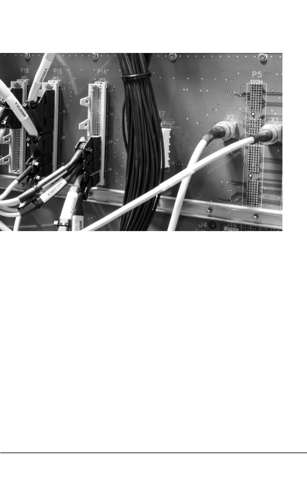
Figure66:Basiccabinet,commonsubrack,connectorsforP15,P16,P18andX1,X2
DN04153465-08-3enTETRASystemRelease5.5–6.5-InstallingtheTB3
146(154)ThisdocumentisthepropertyofCassidianandshouldnotbecopiedorcirculatedwithoutpermission.
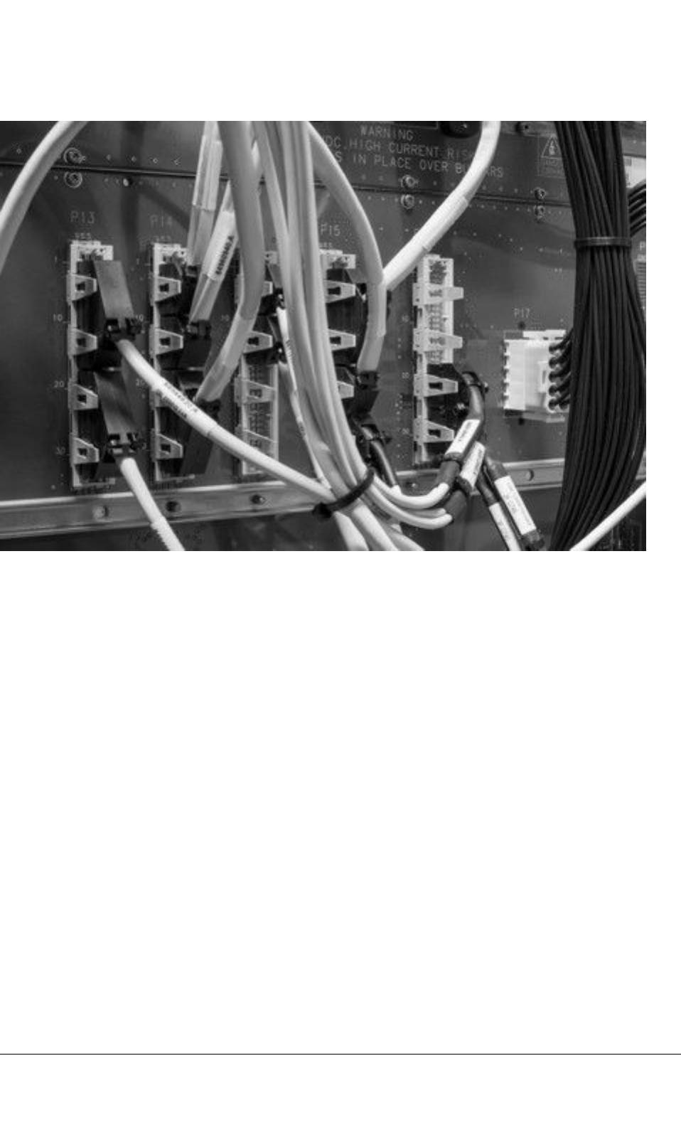
Figure67:Basiccabinet,commonsubrack,connectorsforP13andP14
TETRASystemRelease5.5–6.5-InstallingtheTB3DN04153465-08-3en
ThisdocumentisthepropertyofCassidianandshouldnotbecopiedorcirculatedwithoutpermission.147(154)
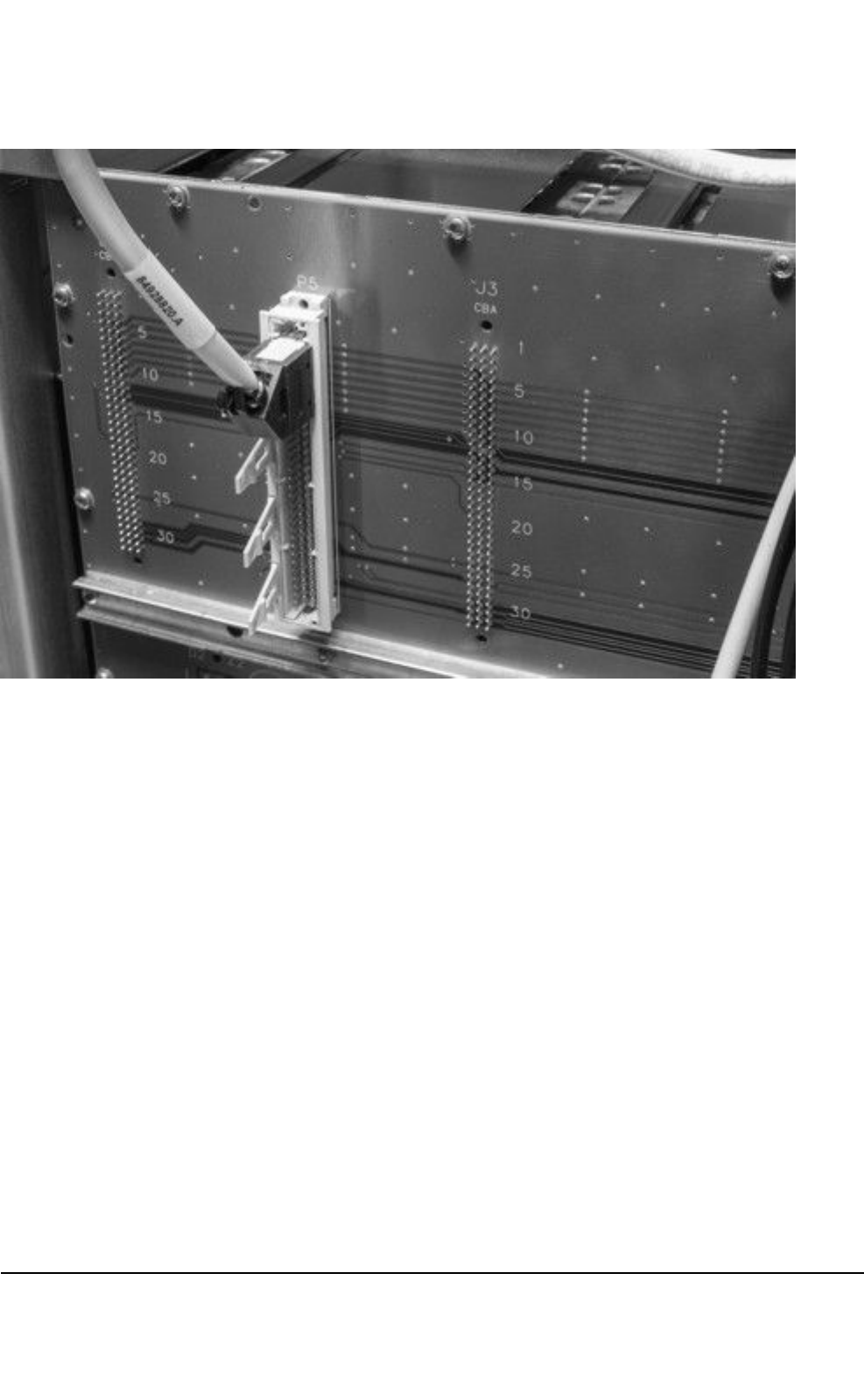
Figure68:Basicorextensioncabinet,TTRXsubrack,connectorforP5:cablepointingup
DN04153465-08-3enTETRASystemRelease5.5–6.5-InstallingtheTB3
148(154)ThisdocumentisthepropertyofCassidianandshouldnotbecopiedorcirculatedwithoutpermission.

Figure69:Basiccabinet,powersubrack,connectorsforP9
TETRASystemRelease5.5–6.5-InstallingtheTB3DN04153465-08-3en
ThisdocumentisthepropertyofCassidianandshouldnotbecopiedorcirculatedwithoutpermission.149(154)
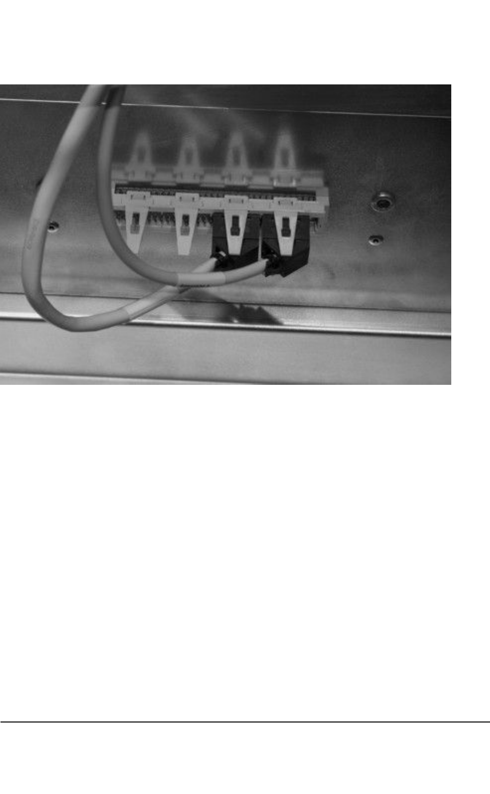
Figure70:Basicandextensioncabinets,connectorsforfans:cablespointingleft
DN04153465-08-3enTETRASystemRelease5.5–6.5-InstallingtheTB3
150(154)ThisdocumentisthepropertyofCassidianandshouldnotbecopiedorcirculatedwithoutpermission.

Glossary
Themeaningsofthetermsandacronymsusedinthisdocumentareexplainedbelow.
ForfurtherinformationonTETRAdenitions,termsandconceptsandthemeaningofallacronyms
andabbreviationsusedinTETRASystemcustomerdocumentation,seedocumentTETRASystem,
Glossary(DN00126469).
Term/acronymMeaning
ALIFAlarmInterface
ATCAuto-tunedCombiner
CSRCommonsubrack
D-BUSInternalcontrol/databusofTBS
DDIVDualDividerunit(usedinextensioncabinetonly)
DDUDualDuplexer
DRMCDualReceiverMulticoupler
EMCElectromagneticcompatibility
ESDElectrostaticDischarge
FSRFansubrack
FXCFlexibleCrossConnect
FXCIFFXCinterface
GPSGlobalPositioningSystem
LEDLightEmittingDiode
LMPLocalManagementPort
MHAMastheadAmplier
MMIManMachineInterface
PCMPulsecodemodulation
PWSRPowersubrack
Q1–BUSO&Mconnectiontotransmissionequipment
RFRadioFrequency
SARSpecicAbsorptionRate
TB3ThirdgenerationTETRABaseStation
TB3350TETRABaseStation,350–368MHz
TETRASystemRelease5.5–6.5-InstallingtheTB3DN04153465-08-3en
ThisdocumentisthepropertyofCassidianandshouldnotbecopiedorcirculatedwithoutpermission.151(154)

Term/acronymMeaning
TB3380TETRABaseStation,380–400MHz
TB3410TETRABaseStation,410–430MHz
TB3450TETRABaseStation,450–470MHz
TB3800TETRABaseStation,806–869MHz
TBCTETRABaseStationController.Twoproductvariantsexist:TBC-UandTBCi.
TBCiTETRABaseStationControllerHW(IPorE1transmission)
TBC-UTETRABaseStationControllerHW(E1transmission)
TBSTETRABaseStation
TRXSRTransceiversubrack
TTRXTETRATransceiver
TXMTXantennamonitoringunit
WBCWidebandCombiner
DN04153465-08-3enTETRASystemRelease5.5–6.5-InstallingtheTB3
152(154)ThisdocumentisthepropertyofCassidianandshouldnotbecopiedorcirculatedwithoutpermission.

INDEX
A
AlarmInterface(ALIFB)...................................62
ATC
troubleshooting............................................92
Auto-tunedCavityCombiner(ATC).................75
C
cabinet
externalconnections....................................30
cabinetinstallation
break-outpanel............................................48
completingthe............................................137
dummyunitsandpanels..............................50
extensioncabinet.........................................47
joiningthecabinets......................................49
liftingthecabinet..........................................37
mountingthecabinet....................................38
openingdirectionofthedoor.......................36
removingthebackpanel..............................37
removingthedoor........................................36
removingtheroof.........................................36
spacerequirements.....................................33
unpackingandchecking..............................34
cabling
380MHzmanualcavitycombiner..............114
410MHzmanualcavitycombiner..............117
alternativecavitycombiners.......................109
alternativecong(WBC&DDU)..................130
auto-tunedcombiners................................112
cabinfrontcabling(2–carrTB3+
WBC)........................................................119
cabinetrearcabling(4–carrTB3+
ATC).........................................................102
cabinettopinterfaces...................................53
Euroconnector..............................................91
extcabinfrontcabling(WBC)....................125
extcabinrearcabling(WBC).....................127
extcabinetrear..........................................107
extensioncabinetfrontcabling..................105
extensioncabinetinterfaces........................56
powersupply................................................57
rearcabling(WBC)....................................123
RFconnectors..............................................75
cautions
antennaconnectors.....................................28
electromagneticelds..................................28
electrostaticdischargeprotection................29
electrostaticsensitivedevices......................29
installationandmaintenance.......................29
storageandtransportation...........................29
D
DDU.................................................................76
DDUtroubleshooting
faultindicationsDDU380and385...............94
Dualduplexer(DDU).....................................119
installation....................................................92
E
Electromagneticcompatibility(EMC)
clamp.....................................................48–49
F
FXCinterface
100/120–ohmE1/T1interface......................71
75–ohmE1interface....................................71
ExternalQ1interface...................................73
LMPinterface...............................................74
G
GlobalPositioningSystem(GPS)....................53
IFconnectors...............................................74
TETRASystemRelease5.5–6.5-InstallingtheTB3DN04153465-08-3en
ThisdocumentisthepropertyofCassidianandshouldnotbecopiedorcirculatedwithoutpermission.153(154)

GlobalPositioningSystem(GPS)antenna
unit
cablefrom....................................................30
H
highgain/lowgainmode..................................90
I
installation
ATC..............................................................90
WBCandDDU.............................................92
installationchecklist........................................53
example.....................................................139
installationtools...............................................30
J
jumpersettings
DRMC..........................................................90
TBC-U..........................................................84
TBCi.............................................................87
jumperingofsubracks
commonsubrack(CSR)...............................77
powersubrack(PWSR)...............................80
TETRAtransceiver(TTRX)subrack............79
M
Mastheadamplier(MHA)...............................90
P
powersupply...................................................57
power-uptest.................................................137
productidenticationlabels.............................32
S
safetyprecautions...........................................19
sitepreparations..............................................30
Specicabsorptionrate(SAR)........................21
subrackjumpers
TETRATransceiver(TTRX).........................79
T
TETRATransceiver(TTRX)............................50
Transmissionunit(FXC)interface...................68
troubleshooting
DDU.............................................................94
TXantennaline
monitoring....................................................62
TXantennamonitoringunit.............................62
TXantennamonitoringunit(TXM)..................94
W
warnings
lethalvoltage................................................19
Safetydistancerequirements......................20
weightandtemperature...............................28
WBCcongurations
2antennas.................................................133
oneantenna...............................................132
road............................................................133
Widebandcombiner(WBC)
cabling........................................................119
installation....................................................92
DN04153465-08-3enTETRASystemRelease5.5–6.5-InstallingtheTB3
154(154)ThisdocumentisthepropertyofCassidianandshouldnotbecopiedorcirculatedwithoutpermission.