CastleNet Technology ASW915N ADSL2/2+ 11n Wireless Router User Manual ASW915N M505N UserMan 20090908
CastleNet Technology Inc. ADSL2/2+ 11n Wireless Router ASW915N M505N UserMan 20090908
UserManual.wiki
>
CastleNet Technology
>
ASW915N User Manual
ASW915N M505N UserMan 20090908
Navigation menu
Upload a User Manual
Namespaces
Wiki Guide
HTML
PDF
Info
Views
User Manual
Discussion / Help
Navigation
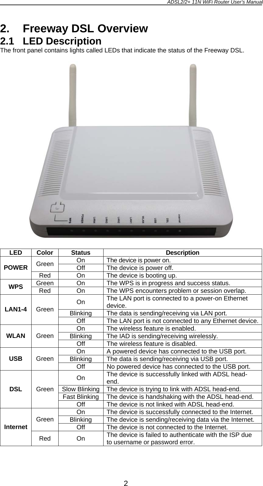
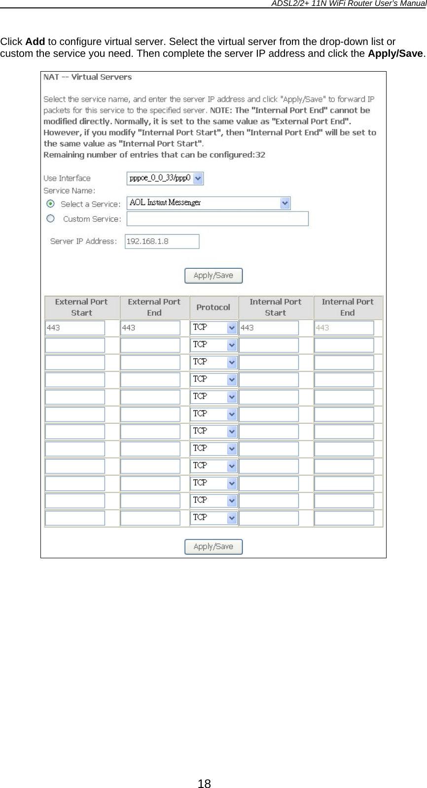
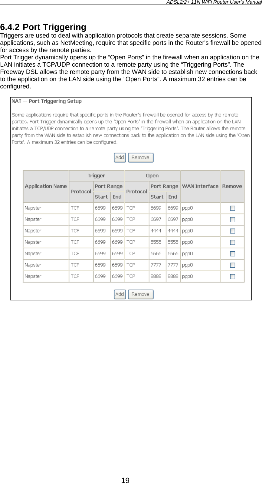
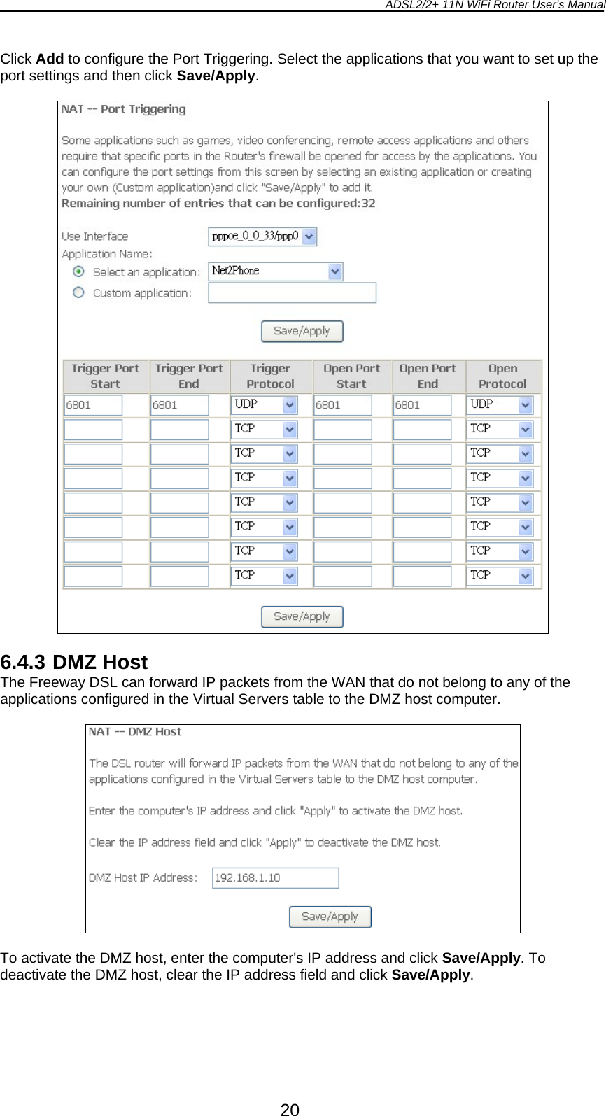
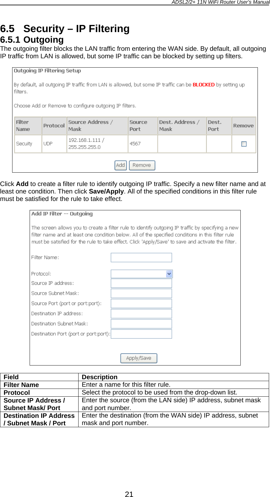
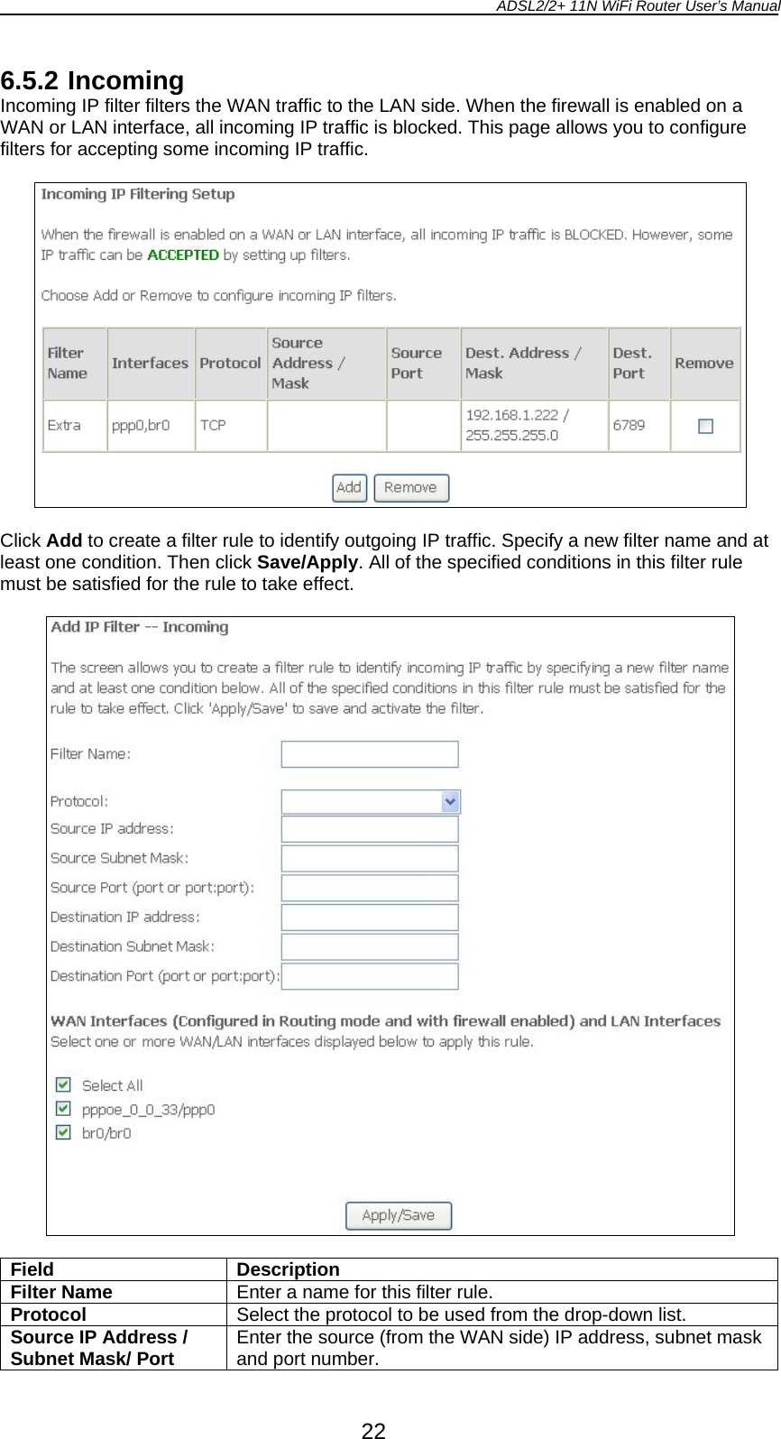
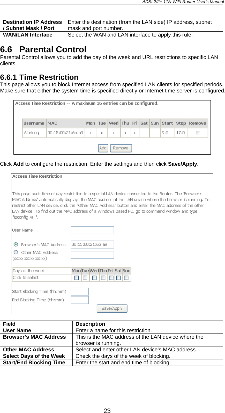
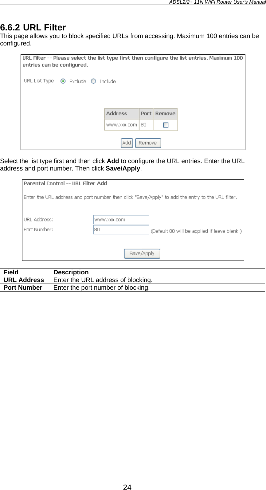
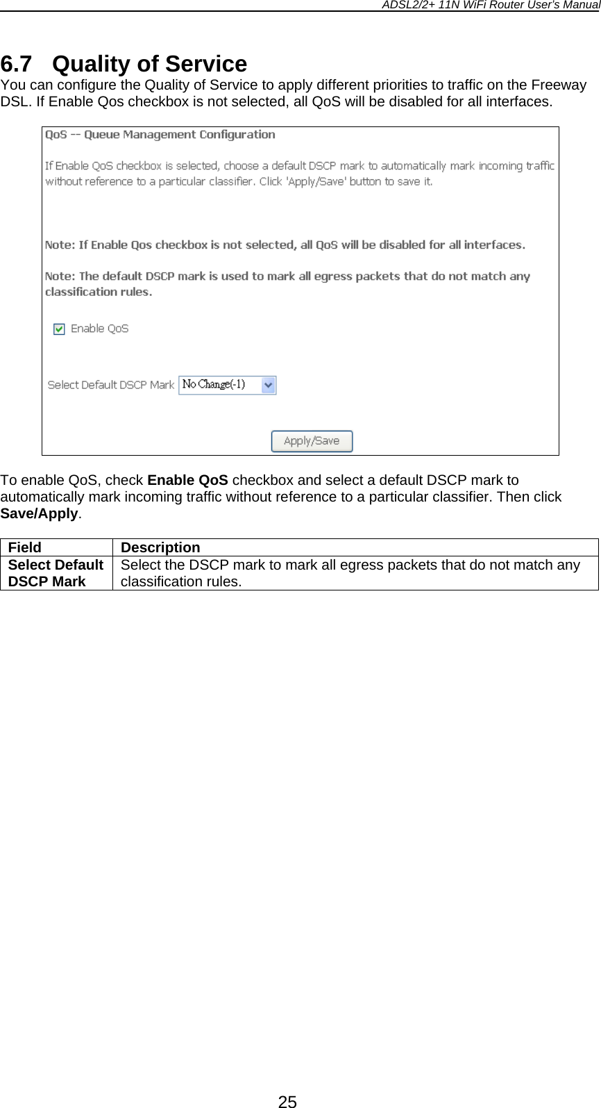
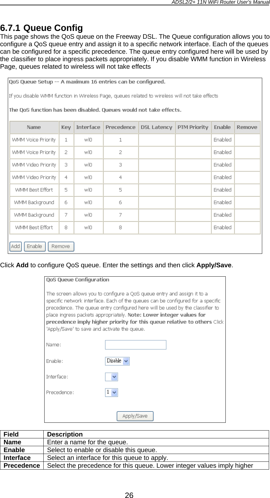
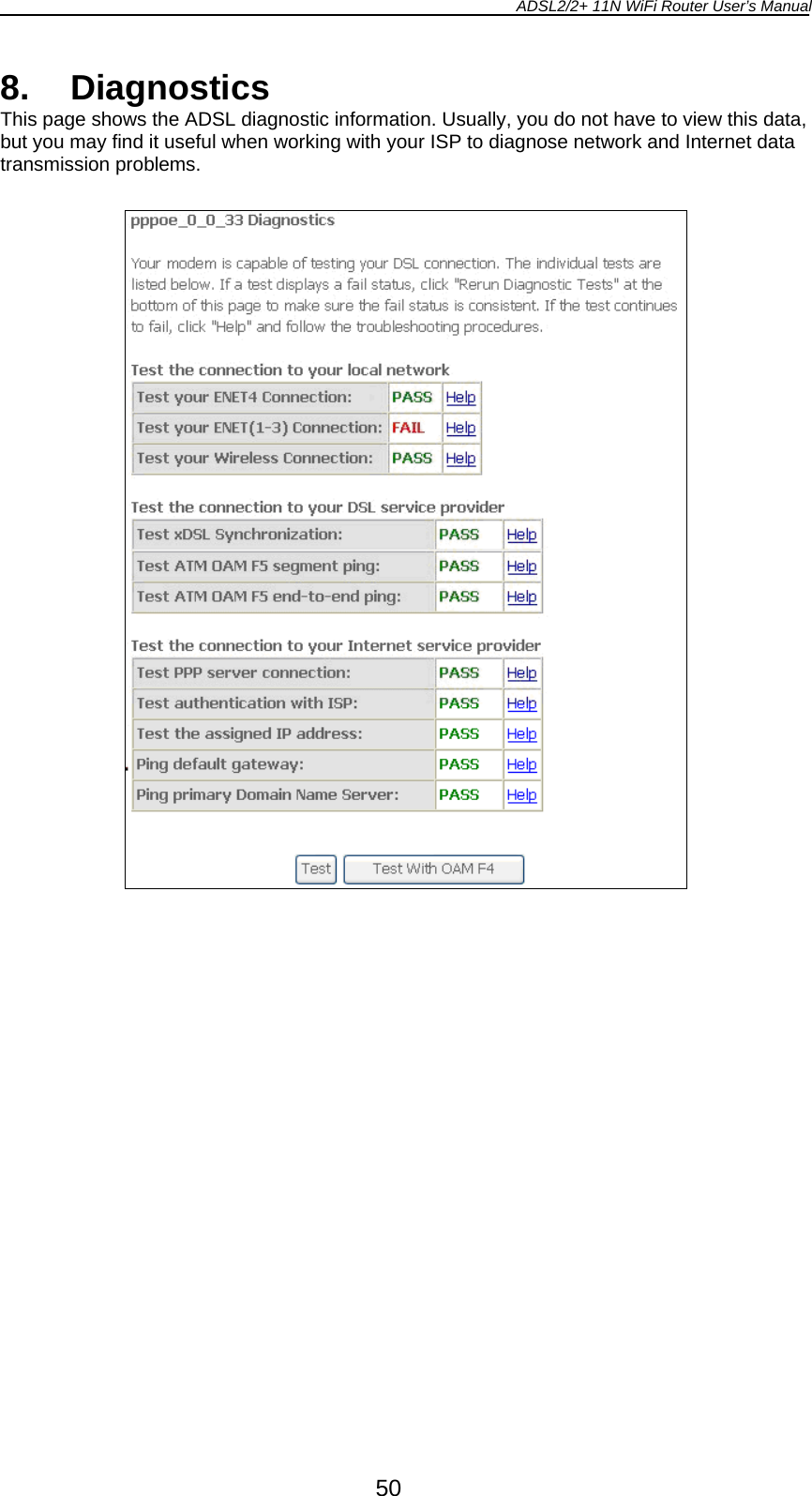
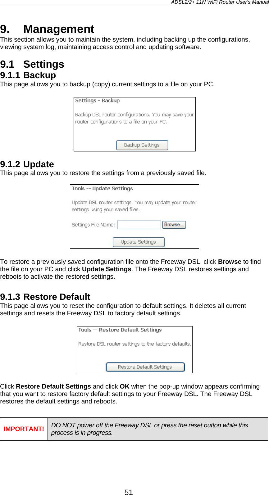
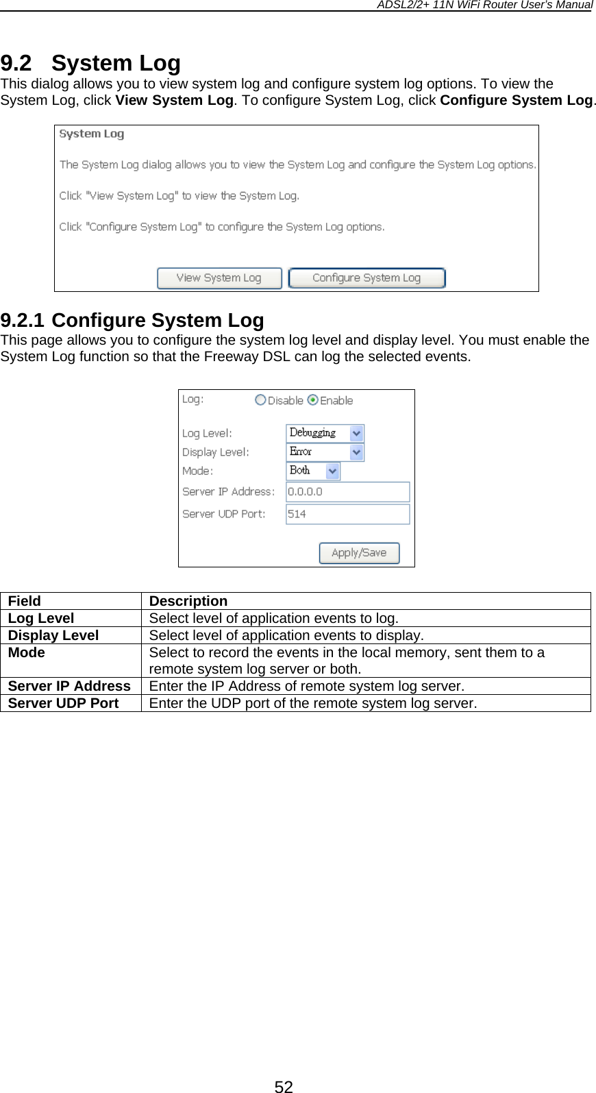
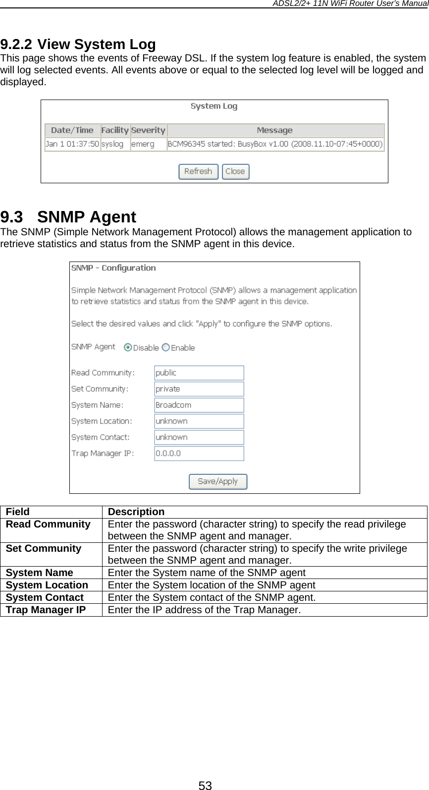
![ADSL2/2+ 11N WiFi Router User’s Manual 1 1. Introduction The Freeway DSL is a highly integrated device which enables ADSL2+, 11N WLAN, Router, Switch,] and File server together. It is positioned to enhance the user's triple play broadband experience with excellent QoS (Quality of Service) and traffic management. This new generation of platforms not only eases the deployment of DSL-based ADSL2+ but also provides new opportunities for the service provider to derive additional value from the emerging IP Video service. The Draft 2.0 IEEE802.11N solution of Freeway DSL can take advantage of the high throughput and extended range with MIMO core technology. Freeway DSL adopts the easy-to-use web-GUI management interface. Its user friendly interface will amaze you with total difference experience. Freeway DSL also supports SNMP agent and TR-069 which enable central management from the central offices and benefit the ISP much. 1.1 General Features y Comply with ITU ADSL, ADSL 2 and ADSL2+ standards y Compliant to DSL Forum TR-048, TR-067 and TR-100 Interoperability Test y Feature-Rich TR-069 supports Remote Registration / Remote Authentication / Remote Configuration y Complete solution for integration of ADSL, Router, Switch, and 11N Draft 2.0 WLAN y Advanced MIMO technology provides enhanced wireless speed/range and wide coverage area y WPS support for easy WLAN client setup y Easily expands network coverage using compatible WDS-enabled AP y Improves on the experience of user for audio, video and voice applications by QoS configuration y Easy to use file server for mass storage file sharing y Security supports WPA/WPA2-PSK, & 64/128-bit WEP Encryption y Remote / Local configuration & management through Web / Telnet configuration & management y Three levels access account management y Support Universal Plug and Play (UPnP) y Device management access control based on source IP addresses and incoming interfaces 1.2 System Requirement In order to use the Freeway DSL, you must have the following: y ADSL service up and running on your telephone line, with at least one public Internet address for your LAN y One or more computers each containing an Ethernet network interface card (NIC) and/or a single computer with a USB port y An Ethernet hub/switch, if you are connecting the device to more than one computer on an Ethernet network y For system configuration using the supplied web-based program: a web browser such as Internet Explorer v5.0 or later, Firefox v2.0 or later, or Netscape v6.1 or later](https://usermanual.wiki/CastleNet-Technology/ASW915N/User-Guide-1166367-Page-5.png)