Cattron North America 7700P15 Industrial Remote Control Transmitter User Manual Paddle Controller Manual Rev 007a
Laird Controls North America Inc. Industrial Remote Control Transmitter Paddle Controller Manual Rev 007a
user manual
©03/2007, CATTRON-THEIMEG
™
- i -
PADDLE CONTROLLER
OPERATION & MAINTENANCE INSTRUCTIONS
CUSTOMER:
MODEL NUMBER:
SERIAL NUMBER:
FREQUENCY ASSIGNMENT:
ADDRESS ASSIGNMENT:
MANUAL P/N: 68C-Paddle Rev. 006, 03/2007

©03/2007, CATTRON-THEIMEG
™
- i -
FCC and IC Statements
FCC and IC labeling can be found inside the user accessible lid of the battery compartment where it is
protected from damage.
FCC Warning Statements
Changes or modifications not expressly approved by the party responsible for compliance could void the
user's authority to operate the equipment
For Low Power License Exempt Units
FCC Warning Statements
Note: This equipment has been tested and found to comply with the limits for a Class A digital device,
pursuant to part 15 of the FCC Rules. These limits are designed to provide reasonable protection against
harmful interference when the equipment is operated in a commercial environment. This equipment
generates, uses, and can radiate radio frequency energy and, if not installed and used in accordance with
the instruction manual, may cause harmful interference to radio communications. Operation of this
equipment in a residential area is likely to cause harmful interference in which case the user will be
required to correct the interference at his own expense
.
This device complies with Part 15 of the FCC rules. Operation is subject to the following two
conditions: (1) This device may not cause harmful interference, and (2) This device must accept any
interference received, including interference that may cause undesired operation.
IC Warning Statements
This device complies with Industry Canada license-exempt RSS standard(s). Operation is subject to the
following two conditions: (1) this device may not cause interference, and (2) this device must accept any
interference, including interference that may cause undesired operation of the device.
Le présent appareil est conforme aux CNR d'Industrie Canada applicables aux appareils radio exempts
de licence. L'exploitation est autorisée aux deux conditions suivantes : (1) l'appareil ne doit pas produire
de brouillage, et (2) l'utilisateur de l'appareil doit accepter tout brouillage radioélectrique subi, même si
le brouillage est susceptible d'en compromettre le fonctionnement
This Class A digital apparatus complies with Canadian ICES-003.
Cet appareil numérique de la classe A est conforme à la norme NMB-003 du Canada
Page ii ©03/2007, CATTRON-THEIMEG
™
IMPORTANT NOTICES
Your new paddle controller has been pre-configured to operate on a specific frequency before leaving
our factory which cannot be changed by yourselves. We have assigned this frequency based upon our
existing records of control equipment previously supplied to yourselves. However, we strongly
recommend you satisfy yourselves that the frequency of your paddle controller does not match that of
any other radio remote control system located at, or around, your operating facility.
WARNING:
CATTRON-THEIMEG
™
MAKES EVERY EFFORT TO ENSURE THE
ADDRESS ASSIGNED TO YOUR NEW CONTROL SYSTEM IS NOT
DUPLICATED BASED UPON RECORDS WHICH INDICATE THE ADDRESSES
OF ALL PAST PORTABLE RADIO REMOTE CONTROL (PRRC) SYSTEMS AS
SHIPPED FROM OUR FACILITY TO YOURS.
THEREFORE IT SHOULD BE FULLY UNDERSTOOD THAT WHEN A PRRC
SYSTEM HAS LEFT OUR FACTORY, CATTRON-THEIMEG
™
HAS NO
CONTROL OF THE ADDRESS ASSIGNMENTS OF ANY OTHER PRRC
SYSTEM(S) THAT MAY BE IN OPERATION IN CLOSE PROXIMITY WITHIN
YOUR OPERATING AREA.
CONSEQUENTLY, AND PURSUANT TO THE ABOVE STATEMENT,
CATTRON-THEIMEG
™
SHALL NOT BE HELD LIABLE FOR PERSONAL
INJURY, DEATH, EQUIPMENT OR PROPERTY DAMAGE ARISING FROM
DUPLICATED ADDRESSES OF RADIO CONTROL SYSTEMS.
©03/2007, CATTRON-THEIMEG
™
- iii -
OPERATION & MAINTENANCE INSTRUCTIONS
IMPORTANT NOTICES, continued.
Your Remote Control System may include an optional ‘Reset’ function that must be activated from the
remote controller before motion control outputs are enabled on the controlled machine. You are advised
to review the customized drawing package provided with your Portable Remote Control (PRC) system
to see if this optional safety feature applies to your PRC system.
Alarm ( )/optional
‘Reset’ ( ) Function
Pushbutton
Controller
PTO Bar
When this ‘Reset’ function applies to your PRC system, the momentary Alarm/Reset pushbutton located
in the center of the controller’s PTO bar must be depressed immediately after the controller has
completed its Power On Self Test, and before holding the PTO bar down to activate a motion control
function. This will sound the system horn (when connected) and reset the Main Equipment Power
Contactor.
This equipment is firmware based, including encoder, decoder, transmitter, and receiver. Any
duplication of operating firmware without written consent of CATTRON-THEIMEG
™
is prohibited.
All firmware, product listings, assembly files, and this manual are protected by U.S. Copyright Laws.
As part of our continuous improvement policy, CATTRON-THEIMEG
™
reserves the right to change
specifications without notice.

Page iv ©03/2007, CATTRON-THEIMEG
™
List of Technical Abbreviations
The following abbreviations (acronyms) are frequently used in CATTRON-THEIMEG
™
Radio
Remote Control Technology and may be used in this manual:
AC Alternating Current LED Light Emitting Diode
ASO Automatic Safety Override MK Metal Keypad
BCH Bose-Chaudhuri-
Hocquenghem (data error
detection routines)
ML Mainline
CMOS Complimentary Metal
Oxide Semiconductor NEMA National Electrical
Manufacturer’s Association
CS Crane Specific Ni-Cad Nickel Cadmium
DC Direct Current OPR Operate
DOC Department of
Communication PRC Portable Remote Control
DP Dual Pressure PTO Push-to-Operate
EDP Electronic Data Processing RF Radio Frequency
EEPROM Electrically Erasable
Programmable Read Only
Memory
RFI Radio Frequency
Interference
EMI Electro-Magnetic
Interference RST Reset Relay
EOT Electrical Overhead
Traveling SP Single Pressure
EPROM Erasable Programmable
Read Only Memory SYNC Synchronization
FCC Federal Communications
Commission TS Transfer Switch
GND Ground VAC Volts Alternating Current
I/O Input/Output VDC Volts Direct Current
LCD Liquid Crystal Display VFD Variable Frequency Drive

©03/2007, CATTRON-THEIMEG
™
- v -
Introduction
How to use this Manual.
This manual contains generic operation and maintenance procedures applicable to the entire series of
CATTRON-THEIMEG
™
Radio Remote Paddle Controllers.
Because no two Paddle Controllers or Portable Remote Control (PRC) applications are exactly the same,
a General Operating Procedure is included in Section 3. This procedure is followed by Operator
Instructions for the two most popular control applications: (1) Cranes, and (2) Locomotives. By
selecting the application (1) or (2) closest to your PRC system, you should be able to familiarize
yourself with the basic operating procedures and control functions that apply to your system.
We emphasize that safety considerations are paramount when using portable remote controllers.
Accordingly, Section 2 should be read in its entirety. Also, for your consideration and possible
adoption, Recommended Safety Rules for Remote Controlled Cranes, and Recommended Safety Rules
for Radio Remote Controlled Locomotives are provided as an addendum at the end of this manual.
Page vi ©03/2007, CATTRON-THEIMEG
™
Safety Summary
WARNING and CAUTION statements have been strategically placed throughout all text prior to
operating or maintenance procedures, practices or conditions considered essential to the protection of
personnel (WARNING), or equipment and property (CAUTION). A WARNING and CAUTION will
apply each time the related step is repeated. Before starting any task, the WARNINGS or CAUTIONS
included in the text for the task shall be reviewed and understood. All WARNINGS and CAUTIONS
appearing in this manual are included below.
WARNINGS.
WARNINGS:
WITH THE EXCEPTION OF LOCOMOTIVES, ALL EQUIPMENT MUST
HAVE A MAINLINE (ML) CONTACTOR INSTALLED AND ALL TRACKED
EQUIPMENT (i.e. CRANES) HAVE A BRAKE INSTALLED.
THE REMOTE CONTROL OPERATE (OPR) RELAY MUST BE CONNECTED
TO THE MAINLINE SO THAT STOP COMMANDS OR FAULT CONDITIONS
MONITORED BY AUTOMATIC SAFETY OVERRIDE (ASO) CIRCUITRY
WILL DE-ENERGIZE THE MAINLINE CONTACTOR AND SET THE
EQUIPMENT BRAKE.
FAILURE TO COMPLY WITH THE ABOVE WARNINGS MAY RESULT IN
SERIOUS INJURY OR DEATH TO PERSONNEL AND DAMAGE TO
EQUIPMENT.
WARNING:
MORE THAN ONE REMOTE CONTROL SYSTEM MAY BE USED AT,
AROUND, OR NEARBY YOUR OPERATING FACILITY. THEREFORE, YOU
MUST INSURE THE ADDRESS CODE AND FREQUENCY OF YOUR
PADDLE CONTROLLER EXACTLY MATCHES THE ADDRESS CODE AND
FREQUENCY OF THE DESIRED EQUIPMENT TO BE OPERATED.
FAILURE TO COMPLY WITH THE ABOVE WARNING MAY RESULT IN
THE UNDESIRED OPERATION OF OTHER EQUIPMENT WHICH, IN
TURN, COULD RESULT IN SERIOUS INJURY OR DEATH TO PERSONNEL
AND DAMAGE TO EQUIPMENT.
WARNING:
NEVER DISABLE THE PUSH TO OPERATE (PTO) BAR SWITCH ON YOUR
REMOTE CONTROLLER. FAILURE TO COMPLY WITH THIS WARNING
MAY RESULT IN DAMAGE TO EQUIPMENT, SERIOUS INJURY, OR
DEATH.
©03/2007, CATTRON-THEIMEG
™
- vii -
WARNINGS, continued.
WARNING:
ON CAB AND REMOTE OPERATED CRANES OR CARRIERS AN AUDIBLE
OR VISUAL WARNING MEANS SHALL BE PROVIDED. IN ADDITION, ALL
EQUIPMENT SHALL HAVE AUDIO OR VISUAL ALARM INDICATIONS
MEETING GOVERNMENTAL REQUIREMENTS. FAILURE TO
IMPLEMENT THIS WARNING MAY RESULT IN SERIOUS INJURY OR
DEATH TO PERSONNEL AND DAMAGE TO EQUIPMENT.
WARNINGS:
UNCODED ADDRESS PLUG(S) SHALL BE PROGRAMMED WITH THE
SAME ADDRESS CODE AS SET IN THE TARGET RECEIVER/DECODER.
IT SHOULD BE FULLY UNDERSTOOD THAT CATTRON-THEIMEG
™
SHALL NOT BE HELD LIABLE FOR PERSONAL INJURY, DEATH,
EQUIPMENT OR PROPERTY DAMAGE ARISING FROM DUPLICATED,
INCORRECTLY PROGRAMMED OR INCORRECT CODE PLUG USAGE.
IT IS YOUR RESPONSIBILITY TO ESTABLISH A PROCEDURE THAT
INSURES ONLY THE CODE PLUG CONFIGURED FOR A PARTICULAR
ADDRESS IS INSTALLED IN EQUIPMENT DESIGNED TO OPERATE ON
THE SAME ADDRESS. NEVER PUT MORE THAN ONE CONTROLLER
INTO OPERATION ON THE SAME ADDRESS AT ANY GIVEN TIME.
CATTRON-THEIMEG
™
STRONGLY ADVISES YOU TO IMPLEMENT AND
REGULARLY UPDATE A REGISTER OF INDIVIDUAL ADDRESSES AND
OPERATING FREQUENCIES ASSIGNED TO EACH PORTABLE RADIO
REMOTE CONTROL (PRRC) SYSTEM LOCATED AT YOUR OPERATING
FACILITY. IN ADDITION, ANY SPARE CODE PLUGS, OR CODE PLUGS
INSTALLED IN EQUIPMENT THAT ARE CONFIGURED FOR THE SAME
ADDRESS OF EQUIPMENT THAT IS IN SERVICE, MUST BE HELD UNDER
LOCK AND KEY BY A DESIGNATED SUPERVISOR.
FAILURE TO COMPLY WITH THESE WARNINGS MAY RESULT IN
OPERATION OF UNDESIRED EQUIPMENT WHICH IN TURN COULD
RESULT IN SERIOUS INJURY OR DEATH TO PERSONNEL AND DAMAGE
TO EQUIPMENT.
Page viii ©03/2007, CATTRON-THEIMEG
™
WARNINGS, continued.
WARNINGS:
ALL TRACKED EQUIPMENT (i.e. LOCOMOTIVES) MUST HAVE A BRAKE
INSTALLED.
THE REMOTE CONTROL OPERATE (OPR) RELAY MUST BE
CONFIGURED SO THAT STOP COMMANDS OR FAULT CONDITIONS
MONITORED BY AUTOMATIC SAFETY OVERRIDE (ASO) CIRCUITRY
WILL SET THE THROTTLE TO IDLE, DISCONNECT THE GENERATOR
FIELD, AND SET THE INDEPENDENT BRAKE.
FAILURE TO COMPLY WITH THE ABOVE WARNINGS MAY RESULT IN
SERIOUS INJURY OR DEATH TO PERSONNEL AND DAMAGE TO
EQUIPMENT.
WARNING:
AFTER CHANGING AN ADDRESS OR FREQUENCY SELECTOR SWITCH,
YOU MUST, IN THE FIRST INSTANCE, INSURE THE TARGETED
MACHINE IS UNDER REMOTE CONTROL BEFORE OPERATING ANY
MOTION FUNCTION SWITCH. THIS MAY BE ACCOMPLISHED BY
OPERATING A NON MOTION FUNCTION SWITCH ON THE REMOTE
CONTROLLER SUCH AS A HORN OR LIGHT.
FAILURE TO COMPLY WITH THE ABOVE WARNING MAY RESULT IN
THE UNDESIRED OPERATION OF OTHER EQUIPMENT WHICH, IN
TURN, COULD RESULT IN SERIOUS INJURY OR DEATH TO PERSONNEL
AND DAMAGE TO EQUIPMENT.
WARNING:
ELECTRICAL POWER TO THE TARGET CONTROLLED EQUIPMENT
MUST BE COMPLETELY ISOLATED TO PREVENT OPERATION UNDER
REMOTE CONTROL IN THE SWITCH DIAGNOSTIC MODE.
FAILURE TO COMPLY WITH THE ABOVE WARNING MAY RESULT IN
THE UNDESIRED OPERATION OF EQUIPMENT WHICH, IN TURN, COULD
RESULT IN SERIOUS INJURY OR DEATH TO PERSONNEL AND DAMAGE
TO EQUIPMENT.
©03/2007, CATTRON-THEIMEG
™
- ix -
WARNINGS, continued.
WARNING:
DUE TO FCC PART 15 AND DOC RSS-210 RADIO TRANSMIT
REGULATIONS, THE OPR OUTPUT TO WHICH YOUR CONTROLLED
EQUIPMENT’S MAINLINE CONTACTOR IS CONNECTED WILL REMAIN
ENERGIZED FOR TEN MINUTES AFTER THE CONTROLLER POWER IS
SET TO ‘OFF’, OR FOR TEN MINUTES AFTER THE LAST TIME A
FUNCTION SWITCH IS ACTIVATED. CONSEQUENTLY, SPECIAL CARE
MUST BE TAKEN IF THE CRANE OR TRACKED MACHINE IS EQUIPPED
WITH A PARKING BRAKE THAT IS CONFIGURED TO ENGAGE WHEN
THE MAINLINE CONTACTOR DE-ENERGIZES.
TO PREVENT A POTENTIALLY HAZARDOUS SITUATION, YOU SHOULD
IMMEDIATELY SELECT THE RED ‘STOP’ FUNCTION ON YOUR
REMOTE CONTROLLER AFTER COMPLETION OF OPERATIONS. SUCH
ACTION WILL INSURE THE PARKING BRAKE (IF EQUIPPED AND
CONFIGURED AS ABOVE) IS SET, PREVENTING UNINTENTIONAL
MOVEMENT OF THE CRANE OR TRACKED MACHINE.
FAILURE TO COMPLY WITH THIS WARNING MAY RESULT IN SERIOUS
INJURY OR DEATH TO PERSONNEL AND DAMAGE TO EQUIPMENT.
CAUTIONS.
CAUTIONS:
(1) CATTRON-THEIMEG
™
Battery Conditioners are designed for use with
CATTRON-THEIMEG
™
Ni-Cad Battery Packs only.
(2) Battery Packs must be removed or disconnected from Battery Conditioners
within 48-hours of achieving the fully charged state.
Failure to comply with these Cautions may result in equipment and/or battery
damage and will void our warranty.
NOTE.
Important Safety Note:
When using the controller, operators are instructed to wear a factory approved
carrying harness with the controller attached at all times. If a controller must be
left unattended, the STOP switch (when installed to the controller) should be
depressed and the controller’s power ON/OFF switch set to ‘OFF’. If the power
ON/OFF switch is a key switch, the key should also be removed to prevent
unauthorized use of the controller.

Page x ©03/2007, CATTRON-THEIMEG
™
Safety Summary
, continued.
GENERAL.
The following are general safety precautions that are not related to any specific procedure and therefore
do not appear elsewhere in this manual. These are general safety precautions and instructions that
people must understand and apply during many phases of operation and maintenance to ensure personal
safety and health and the protection of your company property.
KEEP AWAY FROM LIVE CIRCUITS. Maintenance personnel must observe all safety
requirements at all times. Do not replace components or make adjustments inside the equipment with
the electrical supply turned on. Under certain conditions, danger may exist even when the power control
is in the off position due to charges retained by capacitors. To avoid injuries, always remove power,
discharge and ground a circuit before touching it. Adhere to all lock out/tag requirements.
DO NOT SERVICE OR ADJUST ALONE. Whenever possible, do not attempt internal service or
adjustment of equipment unless another person capable of rendering aid and resuscitation is present.
FINGER RINGS/JEWELRY. Finger rings have caused many serious injuries. Remove rings,
watches and other metallic objects which may cause shock or burn hazards.
SOLDERING/DE-SOLDERING. Avoid breathing fumes generated by soldering/de-soldering.
Perform all operations in a ventilated area. Eye protection is required.
CLEANING SOLVENTS. Some cleaners and solvents have adverse effects on skin, eyes, respiratory
tract and internal organs. These adverse effects range from discomfort to serious injury and death,
depending on the material and degree of exposure. Observe manufacturers’ warning labels and contact
your immediate supervisor if in any doubt.
Remember…. the person now reading these instructions
is primarily responsible for his or her own health and
safety.

©03/2007, CATTRON-THEIMEG
™
- xi -
This page intentionally left blank

©03/2007, CATTRON-THEIMEG
™
- i -
Table of Contents
Front Matter:
FCC and IC Warnings……………………………………………………………………i
Important Notices ……………………………………………………………………ii-iii
List of Technical Abbreviations .................................................................................... i v
How to use this Manual .................................................................................................. v
Safety Summary warnings and cautions..................................................................... vi-x
Section 1 – Product Data and Specifications:
Introduction ................................................................................................................. 1-1
Notable Performance and Safety features ................................................................... 1-2
Frequently asked questions ......................................................................................... 1-3
Standard Specifications ............................................................................................... 1-5
Overview of CATTRON-THEIMEG
™
Remote Control Systems .............................. 1-7
Section 2 – Safety Information:
Safety Considerations ................................................................................................. 2-1
Safety and Security Features ........................................................................... 2-1
Typical Method of Operation incorporating ................................................... 2-2
Safety & Security Features
Radio Control Operator’s Duties – General Equipment ............................................. 2-4
Radio Control Operator’s Duties – E.O.T. Crane ....................................................... 2-8
Radio Control Operator’s Duties – Locomotive ....................................................... 2-12
Section 3 – Operating Instructions:
Controls and Indicators ............................................................................................... 3-1
General Operating Procedure ...................................................................................... 3-5
Typical Crane Control Functions .............................................................................. 3-10
Typical Locomotive Control Functions .................................................................... 3-13
Switch Diagnostic Mode ........................................................................................... 3-17

Page ii ©03/2007, CATTRON-THEIMEG
™
Section 3 – Operating Instructions
, continued
:
Battery Packs and Battery Pack Charging ................................................................ 3-18
Battery Pack Replacement ............................................................................ 3-18
Battery Pack Conditioning/Charging – Ni-Cad Battery packs only ............. 3-20
Pre-Programmed Frequency Selection ..................................................................... 3-22
Pre-Programmed Option Selection ........................................................................... 3-25
Section 4 – Maintenance Instructions:
CATTRON-THEIMEG
™
Maintenance Philosophy ................................................... 4-1
Preventive Maintenance .............................................................................................. 4-1
Troubleshooting .......................................................................................................... 4-2
Troubleshooting Guide ................................................................................... 4-3
Corrective Maintenance .............................................................................................. 4-4
Functional Check ........................................................................................................ 4-4
Replacement Items ...................................................................................................... 4-4
Battery Pack .................................................................................................... 4-4
Address Code Plug .......................................................................................... 4-5
Side Lever (optional item) .............................................................................. 4-9
External Antenna (optional item) ..................................................................... 4-9
Section 5 – Replacement Items and Accessories:
Replacement Items ..................................................................................................... 5-1
Consumable Items and Optional Accessories ............................................................. 5-5
Index.
Appendices:
1. RECOMMENDED SAFETY RULES FOR PORTABLE REMOTE
CONTROLLED (PRC) CRANES.
2. RECOMMENDED SAFETY RULES FOR PORTABLE RADIO REMOTE
CONTROLLED (PRRC) LOCOMOTIVES.

©03/2007, CATTRON-THEIMEG
™
Section 1, Page 1
Section 1 – Product Data & Specifications
Introduction.
The CATTRON-THEIMEG
™
Paddle Controller has a unique shape and style that provide the equipment
operator with a controller that is extremely durable, convenient, and easy to operate. Designed
specifically for heavy duty in harsh working environments, the controller is ideally suitable for both
indoor and outdoor remote control applications within the steel, glass, automotive, shipping, mining,
distribution, and railroad industries. It can be used with all CATTRON-THEIMEG
™
AT Series or MP
Series receiver/decoder units as well as being used with existing CATTRON-THEIMEG
™
PRRC
systems as either a replacement or spare controller.
Your paddle controller is designed to duplicate the operating characteristics of the controls most
commonly found on the controlled machine, therefore the change from manual to radio remote control is
easily learned by the operator.
The CATTRON-THEIMEG
™
paddle controller employs advanced micro-computer electronics and
utilizes surface mount technology. A highly advanced encoder circuit board is built using industrial
grade components and incorporates a powerful microcomputer that uses sophisticated operating
software. The main housing that surrounds and protects the electronic circuitry is made of thick walled,
extruded aluminum with a protective exterior coating. The ends of the housing are rubber-coated plates
that make shock absorbing end ‘bumpers’ and switch/lever guards. Only the highest quality industrial
grade and ‘mil-spec’ switches whose reliability and construction have been field-tested and proven
under extreme conditions are used in your paddle controller. Total water and dust sealing makes these
switches suitable for indoor and outdoor operation.
CATTRON-THEIMEG
™
paddle controllers have room for up to six paddles and can be customized with
additional pushbuttons and toggle switches. In addition, all functions are identified by durable custom
engraved nameplates.
A variety of synthesized and crystal-controlled RF transmitter configurations can be provided with this
controller, allowing operation on licensed and non-licensed VHF and UHF radio channels. In addition,
all CATTRON-THEIMEG
™
paddle controllers meet the FCC's requirements regarding narrow band and
12.5 kHz bandwidths.

Section 1, Page 2 ©03/2007, CATTRON-THEIMEG
™
Notable Performance and Safety Features.
POWER ON SELF TEST (POST) DIAGNOSTICS - When the operator first turns the power switch on,
a sophisticated self-test routine tests the microcomputer and all function switch inputs to detect
unwanted commands in the system. All lever style switches are tested for neutral at this time. A small
speaker beeps twice when the test has been completed satisfactorily.
TRANSMIT/BATTERY CHARGE INDICATOR - The low battery detection circuit is a two stage
design. With a good battery, this indicator light flashes green for each burst of transmitted data. If the
battery voltage drops below the normal level, this LED flashes red during each transmission. A beeping
sound every 10 seconds alerts the operator. When this happens, the battery has approximately one hour
of operating time remaining. The controller stops transmitting before the voltage drops so low that
erratic operation could occur.
BATTERY SAVER – If the controller has not been operated for 15 minutes, a battery management
system detects this inactivity and puts the controller into a ‘deep sleep’ mode. To reset the controller,
the POWER ON/OFF SWITCH must be set to ‘OFF’, and then set to ‘ON’ again.
BATTERY PACK OPTIONS – Alkaline (disposable) & Ni-Cad (rechargeable) battery packs are
available from CATTRON-THEIMEG
™
. Whether you choose disposable or rechargeable battery
packs, changing the battery pack is easy - simply unlatch and open the gasketed battery door, drop the
battery pack in place and close and latch the battery door. There are no wires or connectors to insert into
the battery pack, which improves long-term reliability of this unit.
RUGGED HOUSING - The housing that surrounds and protects the electronic circuitry is a thick-walled
extruded aluminum, which has a hard epoxy powder coated exterior. The ends of the housing are rubber
coated plates that make shock absorbing end 'bumpers’.
DURABLE/OUTDOOR OPERATION – All switches are extremely long life units that are sealed,
providing water and dust protection. All modules and sub-components are gasketed, making your
controller suitable for outdoor operation in rain and snow.
LEVER AND SWITCH PLACEMENT - Each layout is customized according to user needs. The
switch levers are placed far enough apart to accommodate operators who wear heavy gloves.
SAFETY BAR - A long safety bar is provided to function as an enable device to all motion control
switches. It is a large full-length switch that is easily and naturally activated by a convenient and
comfortable part of the operator's hand any time he or she activates a motion switch. This push-to-
operate (PTO) safety bar electronically disconnects all motion switches when it is released, thus
stopping motion commands from these switches. This feature is programmable as some applications
may have lever switches removed from control of the PTO bar. An example of this would be some
locomotive braking functions.
ALARM/RESET FUNCTION (optional) – Your remote controller may incorporate this additional
safety function connected to the momentary pushbutton located in the center of the PTO Safety Bar.
Check the system drawings provided with your remote control system to see if this optional feature
applies to your controller. When applicable to your controller, this pushbutton must be depressed
immediately after the controller has completed its Power On Self Test and before holding the PTO Bar
down to activate a motion control function. This will sound the system horn (when connected) and reset
the main Equipment Power Contactor.

©03/2007, CATTRON-THEIMEG
™
Section 1, Page 3
Notable Performance and Safety Features
, continued
.
LEVER GUARD BAR (optional) – When additional lever switch protection against physical damage is
required, this fixed bar extends upwards from both ends and across the front of the controller.
INTERNAL TILT SWITCH – If the controller is tilted in any axis beyond 60 degrees of upright for
longer than the programmed time (typically 3 seconds), a programmable function is sent automatically.
This function can be assigned in the decoder to stop the equipment, sound an alarm, or both. Reset time
is also programmable.
OPERATING FREQUENCIES - A variety of RF transmitters are available allowing controller
operation in 72-76 MHz, 402-420 MHz, and 450-470 MHz bands on licensed radio channels and 447-
471 MHz on unlicensed channels. Most models in the 450 MHz range are synthesized (16 frequency
channels maximum).
APPLICATIONS - The paddle controller can operate any digital series receiver/decoder built by
CATTRON-THEIMEG
™
. It can be used with existing CATTRON-THEIMEG
™
systems as a
replacement or as an extra transmitter/encoder.
Frequently Asked Questions.
Refer to Table 1-1 below for the most frequently asked questions about your paddle controller.
Table 1-1. Paddle Controller, questions and answers
QUESTION ANSWER
SAFETY
Protection against operator
becoming disabled or falling down? YES - fitted with a tilt switch and Push to Operate (PTO) safety bar switch
as standard
Protection against accidental switch
operation? YES - PTO safety bar switch and toggle switches are protected by housing
design. Spring return to OFF
Simple operation by position and
feel (without looking at controller)? YES - Levers are large enough for easy glove operation. Unique shape
knobs available. Detent for speed steps (5)
High quality custom labeling? YES – Customized text and arrows, large size, durable mylar
Number of functions sent to activate
a motion? TWO (lever and PTO)
Protection against false commands
or data as battery discharges? YES - Low battery warning, then cut off prior to reaching unstable levels
Protection against stray radio signals
and other Remote Control systems? YES - Unique digital address sent at the beginning of each data message.
Protection against other digital data
radio (e.g.. pagers, cell, fax) or
radiation from computer equipment?
YES - Unique (non-standard) data baud rate, each motion command has
data in at least two bytes, very complex data error detection (BCH)
Protection against broken switches
or wiring sending motion
commands?
YES - Switches (potentiometers) are tested for neutral at power on and for
open or shorted wiring before each digital message. Potentiometers tested
for travel beyond end of range and digital A/D converters tested constantly
Withstand static discharge and high
magnetic fields? YES - Unit tested for EMI/RFI by independent lab. Passes and can carry
CE mark. Has been used successfully in high magnetic fields.

Section 1, Page 4 ©03/2007, CATTRON-THEIMEG
™
Frequently Asked Questions
, continued.
Table 1-1. Paddle Controller, questions and answers
QUESTION ANSWER
RELIABILITY
Durable case material? YES - Aluminum with epoxy coating. ‘Neoprene’ rubber bumper ends
Enclosure water/dust/oil resistant? YES - NEMA 12 (IP-65)
Long motion switch operating life? YES – Greater than 1 million operations
Reliable switch wiring? YES – Switches are potentiometers, wired using silver coated multi-strand
teflon coated wire and gold plated connectors. Only 3 wires per ‘switch’
Simple and reliable electrical
connection method to battery? YES - Stainless steel contacts that mate with stainless pads on battery.
Automatic wiping at each insertion into controller
Ability to survive repeated drops on
to concrete floor? YES - Tested by UL labs to mil-specs. Drops will not cause motion
Maximum number of function speed
steps per motor available? Uses potentiometers for all motion functions - 5 step each direction or
stepless typical
State of the art electronic construction
techniques? YES - Machine built PC board (1) using surface mount components
primarily
MAINTAINABILITY
High quality component grades used? YES - Industrial and mil-spec
Internal antenna? YES – Slot design, printed circuit board construction, integral part of lower
front housing on unlicensed controllers. Optional external antennas
available.
Operator diagnostics - battery
condition indication? YES - TWO stage battery condition indicator: flash GREEN – OK. Flash
RED – battery needs changing, audible beeps every 10 seconds anytime
red indicator is flashing.
Operator diagnostics - determining
switch operation condition? YES - Can be placed in switch beep mode by turning on power while unit
is tilted. Beep when a motion control function switch is operated indicates
switch functioning correctly.
Data transmit indicator? YES – GREEN LED flashes with each message being sent (will normally
be synchronized with receiver LED's)
Easy Disassembly and Assembly? YES - by CATTRON-THEIMEG
™
trained customer technicians only.
Minimal wires and few connections
PC diagnostics capability? YES - by CATTRON-THEIMEG
™
trained customer technicians only. PC
testing port, cable, and diagnostic software available. Helps real time
troubleshooting
Test method for RF frequency,
modulation and related tests? YES - by CATTRON-THEIMEG
™
trained customer technicians only. Unit
can be placed in a special test mode by holding PTO bar down while
turning on power (also prevent operator tampering)

©03/2007, CATTRON-THEIMEG
™
Section 1, Page 5
Frequently Asked Questions
, continued.
Table 1-1. Paddle Controller, questions and answers
QUESTION ANSWER
OPERATIONAL FEATURES
FCC approval for narrow band
licensed operation in new 12.5 kHz
channels?
YES - Approved for both non-licensed and licensed services with ongoing
designs for changing USA and Canadian rules and regulations.
Transmitters can be assigned 12.5kHz channels. In addition, units have a
wide number of approvals and frequency ranges for European, UK and
Australian operation
Operational range without Close
Start or Range limited receiver
/decoder (Maximum distance)?
Low power (unlicensed) units typically 300 feet for operation indoors in an
industrial environment. 500 feet outdoors under best conditions
Licensed units typically 800 to 1000 feet indoors. Higher power M840
option is available for operation up to 1 mile outdoors, depending on a
variety of operational and environmental factors which may reduce the
actual operating range. A typical example of the above would be a
locomotive application with TALKBACK
™
operating at 330 mW using an
‘on board’ 5dB antenna.
Special display features for operator? YES - LED (day/night) optional - selects data to be sent e.g., door number
to control. LCD or individual LED's available for Talkback
Weight? 3-paddle unit (P03) weighs approximately 6.5 pounds with battery pack.
Optional lightwieght end-caps available which will reduce weight by 1 lb
Carrying methods available to
provide comfortable, (all day)
operation?
YES - Normally carried using a belt and shoulder harness combination.
This places the unit at the belly. A back support (wide elastic) belt and
shoulder harness combination is optional
Standard Specifications.
Case Material: Epoxy powder coated Anodized Aluminum Extrusion with Molded
Rubber End Caps.
Weight: 3-Paddle Unit (P03) - approximately 6.5 lbs. (3 Kgs), including Battery
Pack.
Dimensions: 3-Paddle Unit (P03) - Height: 5.9" (15 cm) Depth: 6.7" (17 cm) Width:
9.5" (24 cm).
Environmental: -4° F to +140° F (-20° C to +60° C), RH 0 to 95% Non-condensing.
Switch Types: Spring Return to Center Toggle, Maintained Toggle, Momentary
Pushbutton, Rotary Select.
Lever Switch Detented (5-steps each side of center) or Stepless (analog) Spring Forward
Choices: Idle and 8-steps for Throttle, Etc.
Lever Styles: Large Flag. Special Shaped Lever Knobs Optional.

Section 1, Page 6 ©03/2007, CATTRON-THEIMEG
™
Standard Specifications
, continued.
Number of Motor 3 (3-Paddle), 4 (4-Paddle), 5 (5-Paddle), or 6 (6-Paddle). Additional
Functions: motor functions are available – contact your CATTRON-THEIMEG
™
sales representative for details
Auxiliary
Functions: 15 digital ON/OFF.
Push To Operate
Safety Bar: Standard.
Lever Guard Bar: Optional – extends from both sides across the front above the levers.
Labeling: Mylar, Multi-layer, Large
Keylock Switch: Optional (Power ON/OFF).
Antenna: Internal (external antenna optional on licensed versions only).
Low Battery
Indicator: 2 Color LED: GREEN - Battery Normal, RED - Battery Low.
Short Circuit
Protection: Automatically Resettable Polyswitch (no fuses).
Conformal Coating: Standard on PC Board.
Transmitter
Frequency: Synthesized and Crystal Control Models
72-76 MHz, 402-420 MHz, or 450-470 MHz - License Required.
447-471 MHz - No License Required.
Power Output: 450-470 MHz: typically between 20 and 40 mW.
402-420 MHz: typically between 20 and 40 mW.
72-76 MHz: 60 mW Nominal.
447-471 MHz: Maximum According to FCC Rules Part 15.
402-420 MHz, or 450-470 MHz M840 transmitter/transceiver
(licensed) option adjustable from 80-450 mW
Synthesized
Channels: 16 Maximum (Factory Programmed).
©03/2007, CATTRON-THEIMEG
™
Section 1, Page 7
Overview – CATTRON-THEIMEG
™
Radio Remote Control Systems
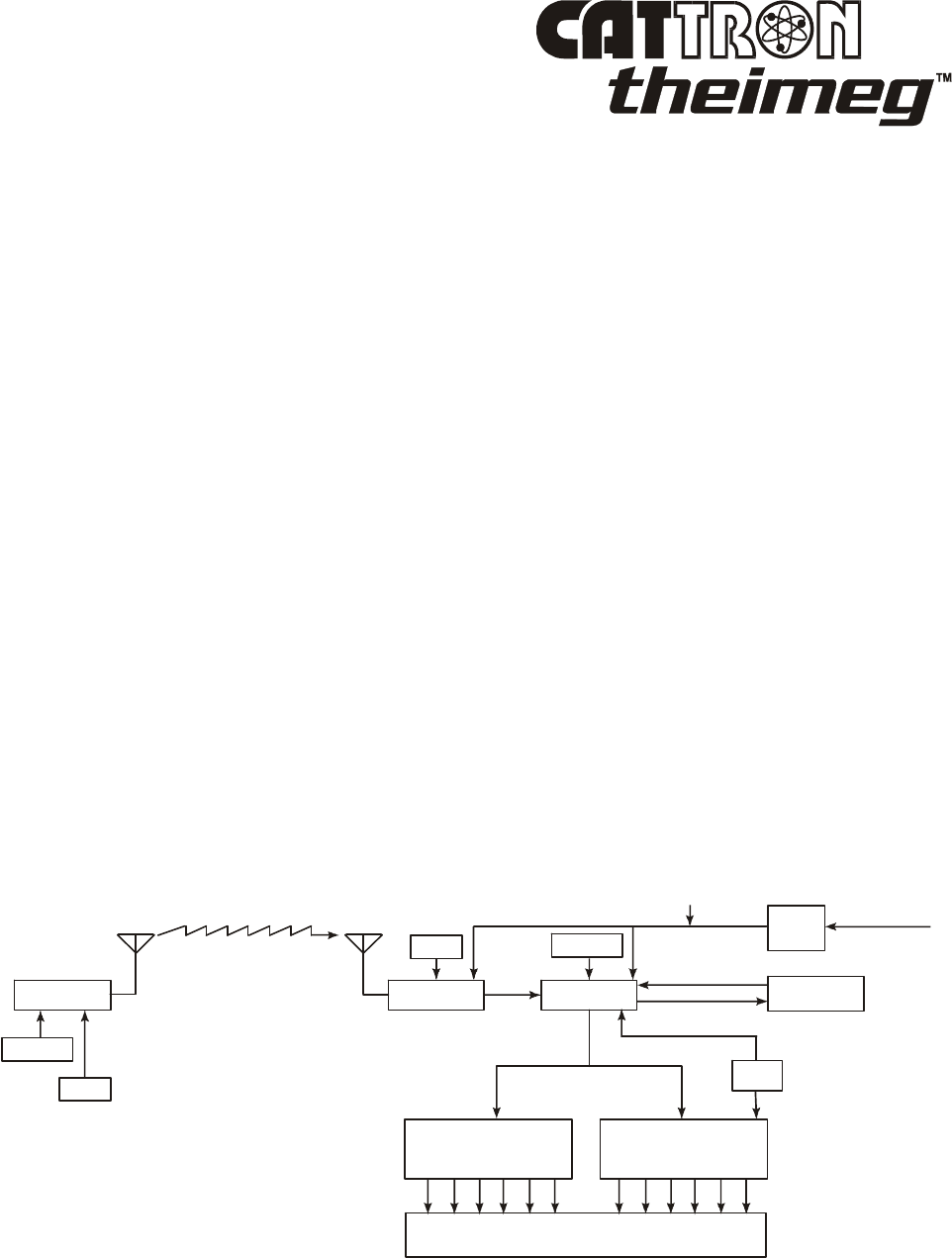
Figure 1-1 below shows a simplified block diagram of a typical CATTRON-THEIMEG
™
radio remote
control system. Refer to this figure and the following paragraphs for a functional description of the
remote control system.
The target receiver/decoder is controlled by the Paddle Controller, which sends signals to the
receiver/decoder using a UHF radio link. The signal is picked up by the antenna and passed on to the
receiver. Provided the frequency of the paddle controller exactly matches that of the target receiver and
passes all data tests, the signal is passed on to the decoder.
The decoder compares the address code of the signal to its own address code. If the signal’s address
code does not match the decoder’s address code, it is ignored and a message is displayed on a system
status display usually located in the receiver/decoder unit. If the address code is correct, the decoder
processes the message and energizes and de-energizes the appropriate control and auxiliary function
relays located within the control system.
An Automatic Safety Override (ASO) function continually monitors the state of any directional relay
output (i.e. Forward/Reverse). If a monitored relay electrically fails closed without a command from the
controller, the ASO circuit logic de-energizes the master output relay (OPR) which should be connected
to the mainline contactor of your controlled machine.
During operation, the microprocessor on the decoder board resets multiple watchdog timer circuits
whenever valid messages are received and decoded. If the microprocessor fails to reset the watchdog
timers, the timer circuits shut down and de-activate all relay outputs. The decoder microprocessor
requires continuously valid transmitted signals to be received and decoded or all relay output functions
will be de-activated unless programmed otherwise. It should be noted that the mainline control relay
(OPR) may be maintained for up to 10 minutes, depending on system configuration.
Figure 1-1. Typical Radio Remote Control System - simplified block diagram
CONTROLLER
ADDRESS
ADDRESS
FREQ
FREQ
Rx
Tx
RECEIVER
MACHINE WIRING
DECODER
12 VDC
POWER
SUPPLY
WATCHDOG
TIMER
MAINS INPUT
50-60 HZ
AUXILIARY FUNCTION
OUTPUT RELAYS
DIRECTIONAL
OUTPUT RELAYS
ASO
END OF SECTION

Section 1, Page 8 ©03/2007, CATTRON-THEIMEG
™
This page intentionally left blank

©03/2007, CATTRON-THEIMEG
™
Section 2, Page 1
Section 2 – Safety Information
Safety Considerations.
CATTRON-THEIMEG
™
believes that to safely operate any remotely controlled equipment, the overall
system needs to be configured so that movement or operation of the equipment will take place only
when the device is commanded to move or operate. For example, overhead cranes or locomotives must
be equipped with a braking system that can only be released when an electrical signal is sent to the
motor. Removal of electrical power or loss of the radio transmitted signal results in application of the
brakes. On cranes, this is provided when a CATTRON-THEIMEG
™
Electro-Hydraulic brake package
is installed – contact the factory for details. On locomotives, an air valve opens, applying independent
braking and the throttle returns to idle.
In keeping with this philosophy - NO COMMAND, NO MOVEMENT - CATTRON-THEIMEG
™
has
designed your radio remote control system with the following safety and security features which may, at
your request, be modified to meet specific operating requirements. CATTRON-THEIMEG
™
engineers
are always available to work with you to provide optimum operating system safety.
Safety & Security Features.
Unique address code: Each controller and receiver/decoder pair is configured with a
unique address code so that the equipment will respond only to the controller whose
address code matches that of the decoder.
Intelligent digital message protocol: CATTRON-THEIMEG
™
remote control systems
utilize a unique message protocol for industrial control applications rather than the
customary Electronic Data Processing (EDP) type of message format.
Power ON/OFF switch: The controller has a power ON/OFF Key or Toggle Switch that
must be set to ‘ON’ in order to send commands to the receiver/decoder. If the power
ON/OFF Switch is set to ‘OFF’, the decoder will remove all commands from the
controlled machinery, stopping all movement. However, the mainline control relay (OPR)
may be maintained for up to 10 minutes, depending on system configuration.
Operate relay (OPR): The operate (OPR) output relay shall be wired to control a user-
provided electro-magnetic power contactor. The electro-magnetic contactor opens and
closes the main electrical supply circuit(s) to the controlled device.
Automatic Safety Override: The Automatic Safety Override (ASO) function continually
monitors all selected decoder directional relay outputs. If a directional relay closes without
command from the controller, the Operate (OPR) Relay immediately de-energizes. This
prevents any movement of the controlled machine without command from the controller.

Section 2, Page 2 ©03/2007, CATTRON-THEIMEG
™
Safety & Security Features,
continued.
Data Error Checking: All communications from the controller to the receiver/decoder
contain error-checking information (BCH data error detection routines). The entire data
command packet must pass error detection tests before being processed.
Push-To-Operate (PTO) Bar: This easily activated switch bar must be released when
power is turned on, then pressed and held to enable the motion switch functions. Releasing
the PTO during normal operation causes the controller to send neutral commands to the
receiver/decoder. In certain cases the PTO will be programmed NOT to enable or disable a
particular function switch, i.e. some locomotive braking functions. Refer to the schematic
drawing for your custom controller serial number to understand its configuration.
NOTE: Holding the PTO bar down when power is turned on places the
controller in a technical diagnostic mode. Refer to Maintenance
Instructions (Section 4) for details.
Optional ‘Keyless Entry Code’: This available feature requires an operator to activate a
series of switches correctly before the controller power is turned on.
Typical method of operation (incorporating above safety features).
The Operate (OPR) relay is energized for the first time when:
The controller’s Power ON/OFF Switch is set to ‘ON’ and the target receiver/decoder has power
applied. With these conditions satisfied, a matching address code is sent by way of RF signal from the
controller to the decoder.
The OPR relay is wired to the mainline (ML) contactor on the crane. Once the mainline is energized, a
continuously repeated valid signal must be received for function outputs to engage. If this signal is
interrupted for any reason, all function outputs will turn off unless programmed otherwise.
When operating within the USA, FCC rules state that RF transmitters in non-licensed controllers must
switch off within five seconds after the operator releases a function button. Consequently, the OPR
output is programmed to stay on for ten minutes after the last valid message is received. During this
time all Automatic Safety Override (ASO) monitored outputs must stay off or the ASO sensing in the
decoder will interrupt this hold up time, de-energizing OPR.
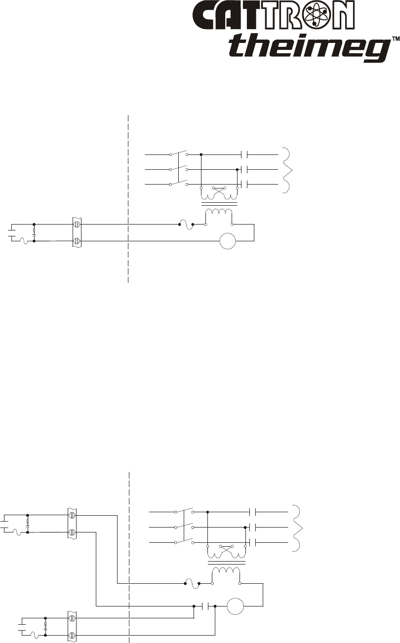
Figure 2-1 opposite shows an Operate (OPR) contact wired directly to the mainline (ML) contactor.
Setting the controller’s Power ON/OFF Switch to ‘ON’ will energize the mainline contactor.
An auxiliary function may be used as a Reset (RST) output that will only be effective when the Operate
(OPR) relay has been closed. Momentary closure of the Reset (RST) relay picks up the mainline (ML)
contactor, which is maintained under control of the OPR. Thus, power is supplied to the controlled
device. If OPR opens, the mainline contactor releases, removing power from the controlled device and
stopping all motion.
©03/2007, CATTRON-THEIMEG
™
Section 2, Page 3
Typical method of operation
(continued).
Figure 2-1. Operate (OPR) contact wiring
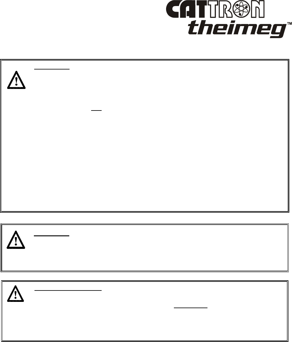
Figure 2-2 below shows the Operate (OPR) relay and optional Reset (RST) relay wired to control a
mainline (ML) contactor. This configuration requires the operator to activate the reset function on the
controller after he/she has turned the unit on. Once reset, the ML contactor stays energized until OPR
de-energizes.
In addition to being energized by the presence of a signal from the controller, OPR is under supervision
of the Automatic Safety Override (ASO) circuit. The ASO circuit disables the OPR (shutting down the
controlled machinery) if a directional output relay is active when no corresponding command is being
received from the controller. In this event, no action is required by the operator to stop the equipment.
The ASO safety circuitry will stop motion automatically without any operator command when a
directional output relay fault is detected.
Figure 2-2. Operate (OPR) contactor and Reset Relay (RST) wiring
120V
L1 ML
ML
MANUAL
DISCONNECT
L2
L3
LL1
LL2
LL3
TO
MOTOR
RECEIVER/DECODER
EXISTING CONTROLS
OPR
R
C
5.0A
OPR
120V
RST
R
R
C
C
5.0A
5.0A
L1 ML
ML ML
MANUAL
DISCONNECT
L2
L3
LL1
LL2
LL3
TO
MOTOR
RECEIVER/DECODER
EXISTING CONTROLS
Section 2, Page 4 ©03/2007, CATTRON-THEIMEG
™
Radio Control Operator’s Duties – General Equipment.
WARNINGS:
WITH THE EXCEPTION OF LOCOMOTIVES, ALL EQUIPMENT MUST
HAVE A MAINLINE (ML) CONTACTOR INSTALLED AND ALL
TRACKED EQUIPMENT (i.e. CRANES) HAVE A BRAKE INSTALLED.
THE REMOTE CONTROL OPERATE (OPR) RELAY MUST BE
CONNECTED TO THE MAINLINE SO THAT STOP COMMANDS OR
FAULT CONDITIONS MONITORED BY AUTOMATIC SAFETY
OVERRIDE (ASO) CIRCUITRY WILL DE-ENERGIZE THE MAINLINE
CONTACTOR AND SET THE EQUIPMENT BRAKE.
FAILURE TO COMPLY WITH THE ABOVE WARNINGS MAY RESULT IN
SERIOUS INJURY OR DEATH TO PERSONNEL AND DAMAGE TO
EQUIPMENT.
WARNING:
MORE THAN ONE REMOTE CONTROL SYSTEM MAY BE USED AT,
AROUND, OR NEARBY YOUR OPERATING FACILITY. THEREFORE,
YOU MUST INSURE THE ADDRESS CODE AND FREQUENCY OF YOUR
PADDLE CONTROLLER EXACTLY MATCHES THE ADDRESS CODE AND
FREQUENCY OF THE DESIRED EQUIPMENT TO BE OPERATED.
FAILURE TO COMPLY WITH THE ABOVE WARNING MAY RESULT IN
THE UNDESIRED OPERATION OF OTHER EQUIPMENT WHICH, IN
TURN, COULD RESULT IN SERIOUS INJURY OR DEATH TO
PERSONNEL AND DAMAGE TO EQUIPMENT.
WARNING:
ON CAB AND REMOTE OPERATED CRANES OR CARRIERS AN AUDIBLE
OR VISUAL WARNING MEANS SHALL BE PROVIDED. IN ADDITION,
ALL EQUIPMENT SHALL HAVE AUDIO OR VISUAL ALARM
INDICATIONS MEETING GOVERNMENTAL REQUIREMENTS. FAILURE
TO IMPLEMENT THIS WARNING MAY RESULT IN SERIOUS INJURY OR
DEATH TO PERSONNEL AND DAMAGE TO EQUIPMENT.

©03/2007, CATTRON-THEIMEG
™
Section 2, Page 5
Radio Control Operator’s Duties – General Equipment,
continued.
WARNING:
DUE TO FCC PART 15 AND DOC RSS-210 RADIO TRANSMIT
REGULATIONS, THE OPR OUTPUT TO WHICH YOUR CONTROLLED
EQUIPMENT’S MAINLINE CONTACTOR IS CONNECTED WILL REMAIN
ENERGIZED FOR TEN MINUTES AFTER THE CONTROLLER POWER IS
SET TO ‘OFF’, OR FOR TEN MINUTES AFTER THE LAST TIME A
FUNCTION SWITCH IS ACTIVATED. CONSEQUENTLY, SPECIAL CARE
MUST BE TAKEN IF THE CRANE OR TRACKED MACHINE IS EQUIPPED
WITH A PARKING BRAKE THAT IS CONFIGURED TO ENGAGE WHEN
THE MAINLINE CONTACTOR DE-ENERGIZES.
TO PREVENT A POTENTIALLY HAZARDOUS SITUATION, YOU SHOULD
IMMEDIATELY SELECT THE RED ‘STOP’ FUNCTION ON YOUR REMOTE
CONTROLLER AFTER COMPLETION OF OPERATIONS. SUCH ACTION
WILL INSURE THE PARKING BRAKE (IF EQUIPPED AND CONFIGURED
AS ABOVE) IS SET, PREVENTING UNINTENTIONAL MOVEMENT OF THE
CRANE OR TRACKED MACHINE.
FAILURE TO COMPLY WITH THIS WARNING MAY RESULT IN SERIOUS
INJURY OR DEATH TO PERSONNEL AND DAMAGE TO EQUIPMENT.
WARNING:
NEVER DISABLE THE PUSH TO OPERATE (PTO) BAR SWITCH ON YOUR
REMOTE CONTROLLER. FAILURE TO COMPLY WITH THIS WARNING
MAY RESULT IN DAMAGE TO EQUIPMENT, SERIOUS INJURY, OR
DEATH.
Important Safety Note:
When using the controller, operators are instructed to wear a factory approved
carrying harness with the controller attached at all times. If a controller must be
left unattended, the STOP switch (when installed to the controller) should be
depressed and the controller’s power ON/OFF switch set to ‘OFF’. If the power
ON/OFF switch is a key switch, the key should also be removed to prevent
unauthorized use of the controller.

Section 2, Page 6 ©03/2007, CATTRON-THEIMEG
™
Radio Control Operator’s Duties – General Equipment,
continued.
The following procedures provide general guidelines for radio control operation of equipment and
should not be used as a substitute for your plant operating procedures.
1. Before operating equipment, carry out the following:
a. Insure the address code and frequency of your paddle controller exactly matches the
address code and frequency of the target equipment to be operated.
The address and frequency assigned to your controller is recorded (1) on the front page of
this manual, and (2) on a serial tag located inside the battery door. The address and
frequency of the target receiver/decoder is recorded (1) on the front page of the manual
supplied with the portable remote control system, and (2) on a label located inside the
receiver/decoder.
If a controller having the wrong address code and frequency is selected, the target
equipment will not operate. However, other equipment located at, around, or nearby your
facility may become operational.
NOTES: If you are not familiar with the controls and indicators on your controller,
please refer to ‘Controls and Indicators’ in Section 3 of this manual and the
operational description provided with your controller.
Some controllers have two power ON/OFF switches (a Keyswitch and a Toggle
switch). Both of these switches must be set to ‘ON’ for power to be applied to
the controller.
b. Set the controller’s Power ON/OFF Switch(es) to the ‘ON’ position. When transmitting
with a good battery, two short ‘beeps’ will be heard immediately after the Power
ON/OFF Switch is set to ‘ON’ and a green TRANSMIT LED will ‘flash’ rhythmically.
When the battery starts to go low, the green LED changes to a red LOW BATTERY
LED which ‘flashes’ continuously. This means you should change or re-charge the
battery pack as soon as possible - refer to Battery Packs and Battery Pack Charging in
Section 3 of this manual.
c. When installed, depress the ALARM/RESET push button switch located in the center of
the PTO bar (this is normally an optional function that sounds the equipment alarm or
horn and resets the main power contactor).
d. Check each function independently to be sure that equipment is responding correctly.
e. Where a limit switch is provided, you should check the limit switch at the beginning of
each shift as defined by your plant operating procedures.
f. Check Range Limiting if used – refer to Appendix ‘A’ of the manual supplied with your
PRC system.
g. Check STOP operation
h. Check brake operation.

©03/2007, CATTRON-THEIMEG
™
Section 2, Page 7
Radio Control Operator’s Duties – General Equipment,
continued.
2. You must report all defective or missing safety equipment, mechanical or electrical defects to
your supervisor without delay. Do not continue operation until fully repaired.
3. If anyone is in the path of equipment travel, stop and sound the alarm before proceeding. Do not
proceed until the pathway is clear
4. Persons operating this equipment shall not use a limit stop as a utility stopping device.
5. When leaving the equipment area for any reason, set the controller’s Power ON/OFF Switch(es)
to the ‘OFF’ position. If a Key Switch is installed, remove the key from the controller and keep
it on your person.
6. Do not allow any unauthorized person to operate the controller.
7. Do not operate the controller at a distance where the equipment and all surrounding objects are
not visible.
8. Do not attempt to override any of the safety features built into the Radio Control System.
9. If, for any reason, you or anyone has to board the radio controlled equipment, set the controller’s
Power ON/OFF Switch(es) to the ‘OFF’ position. If a Key Switch is installed, remove the key
from the controller and keep it on your person.
Section 2, Page 8 ©03/2007, CATTRON-THEIMEG
™
Radio Control Operator’s Duties – Electrical Overhead
Traveling (EOT) Crane.
WARNINGS:
ALL EQUIPMENT MUST HAVE A MAINLINE (ML) CONTACTOR
INSTALLED AND ALL TRACKED EQUIPMENT (i.e. CRANES) HAVE A
BRAKE INSTALLED.
THE REMOTE CONTROL OPERATE (OPR) RELAY MUST BE
CONNECTED TO THE MAINLINE SO THAT STOP COMMANDS OR
FAULT CONDITIONS MONITORED BY AUTOMATIC SAFETY OVERRIDE
(ASO) CIRCUITRY WILL DE-ENERGIZE THE MAINLINE CONTACTOR
AND SET THE EQUIPMENT BRAKE.
FAILURE TO COMPLY WITH THE ABOVE WARNINGS MAY RESULT IN
SERIOUS INJURY OR DEATH TO PERSONNEL AND DAMAGE TO
EQUIPMENT.
WARNING:
MORE THAN ONE REMOTE CONTROL SYSTEM MAY BE USED AT,
AROUND, OR NEARBY YOUR OPERATING FACILITY. THEREFORE,
YOU MUST INSURE THE ADDRESS CODE AND FREQUENCY OF YOUR
PADDLE CONTROLLER EXACTLY MATCHES THE ADDRESS CODE AND
FREQUENCY OF THE DESIRED EQUIPMENT TO BE OPERATED.
FAILURE TO COMPLY WITH THE ABOVE WARNING MAY RESULT IN
THE UNDESIRED OPERATION OF OTHER EQUIPMENT WHICH, IN
TURN, COULD RESULT IN SERIOUS INJURY OR DEATH TO PERSONNEL
AND DAMAGE TO EQUIPMENT.
WARNING:
ON CAB AND REMOTE OPERATED CRANES OR CARRIERS AN AUDIBLE
OR VISUAL WARNING MEANS SHALL BE PROVIDED. IN ADDITION, ALL
EQUIPMENT SHALL HAVE AUDIO OR VISUAL ALARM INDICATIONS
MEETING GOVERNMENTAL REQUIREMENTS. FAILURE TO
IMPLEMENT THIS WARNING MAY RESULT IN SERIOUS INJURY OR
DEATH TO PERSONNEL AND DAMAGE TO EQUIPMENT.
©03/2007, CATTRON-THEIMEG
™
Section 2, Page 9
Radio Control Operator’s Duties – EOT Crane
, continued.
WARNING:
DUE TO FCC PART 15 AND DOC RSS-210 RADIO TRANSMIT
REGULATIONS, THE OPR OUTPUT TO WHICH YOUR CONTROLLED
EQUIPMENT’S MAINLINE CONTACTOR IS CONNECTED WILL REMAIN
ENERGIZED FOR TEN MINUTES AFTER THE CONTROLLER POWER IS
SET TO ‘OFF’, OR FOR TEN MINUTES AFTER THE LAST TIME A
FUNCTION SWITCH IS ACTIVATED. CONSEQUENTLY, SPECIAL CARE
MUST BE TAKEN IF THE CRANE OR TRACKED MACHINE IS EQUIPPED
WITH A PARKING BRAKE THAT IS CONFIGURED TO ENGAGE WHEN
THE MAINLINE CONTACTOR DE-ENERGIZES.
TO PREVENT A POTENTIALLY HAZARDOUS SITUATION, YOU SHOULD
IMMEDIATELY SELECT THE RED ‘STOP’ FUNCTION ON YOUR
REMOTE CONTROLLER AFTER COMPLETION OF OPERATIONS. SUCH
ACTION WILL INSURE THE PARKING BRAKE (IF EQUIPPED AND
CONFIGURED AS ABOVE) IS SET, PREVENTING UNINTENTIONAL
MOVEMENT OF THE CRANE OR TRACKED MACHINE.
FAILURE TO COMPLY WITH THIS WARNING MAY RESULT IN SERIOUS
INJURY OR DEATH TO PERSONNEL AND DAMAGE TO EQUIPMENT.
WARNING:
NEVER DISABLE THE PUSH TO OPERATE (PTO) BAR SWITCH ON YOUR
REMOTE CONTROLLER. FAILURE TO COMPLY WITH THIS WARNING
MAY RESULT IN DAMAGE TO EQUIPMENT, SERIOUS INJURY, OR
DEATH.
Important Safety Note:
When using the controller, operators are instructed to wear a factory approved
carrying harness with the controller attached at all times. If a controller must be
left unattended, the STOP switch (when installed to the controller) should be
depressed and the controller’s power ON/OFF switch set to ‘OFF’. If the power
ON/OFF switch is a key switch, the key should also be removed to prevent
unauthorized use of the controller.

Section 2, Page 10 ©03/2007, CATTRON-THEIMEG
™
Radio Control Operator’s Duties – EOT Crane
, continued.
The following procedures provide general guidelines for radio control operation of an EOT crane and
should not be used as a substitute for your plant operating procedures. Please note that a complete set
of Recommended Safety Rules for Cranes is provided at the end of this manual.
1. Before lifting any loads, carry out the following:
a. Insure the address code and frequency of your paddle controller exactly matches the
address code and frequency of the target equipment to be operated.
The address and frequency assigned to your controller is recorded (1) on the front page of
this manual, and (2) on a serial tag located inside the battery door. The address and
frequency of the target receiver/decoder is recorded (1) on the front page of the manual
supplied with the portable remote control system, and (2) on a label located inside the
receiver/decoder.
If a controller having the wrong address code and frequency is selected, the target
equipment will not operate. However, other equipment located at, around, or nearby your
facility may become operational.
NOTES: If you are not familiar with the controls and indicators on your controller,
please refer to ‘Controls and Indicators’ in Section 3 of this manual and the
operational description provided with your controller.
Some controllers have two power ON/OFF switches (a Keyswitch and a Toggle
switch). Both of these switches must be set to ‘ON’ for power to be applied to
the controller.
b. Set the controller’s Power ON/OFF Switch(es) to the ‘ON’ position. When transmitting
with a good battery, two short ‘beeps’ will be heard immediately after the Power
ON/OFF Switch is set to ‘ON’ and a green TRANSMIT LED will ‘flash’ rhythmically.
When the battery starts to go low, the green LED changes to a red LOW BATTERY
LED which ‘flashes’ continuously. This means you should change or re-charge the
battery pack as soon as possible - refer to Battery Packs and Battery Pack Charging in
Section 3 of this manual.
c. When installed, depress the ALARM/RESET push button switch located in the center of
the PTO bar (this is normally an optional function that sounds the equipment alarm and
resets the main power contactor).
d. Where a limit switch is provided, you should check the limit switch at the beginning of
each shift as defined by your plant operating procedures.
e. Check each function independently to be sure that equipment is responding correctly.
f. Check range limiting if used – refer to Appendix ‘A’ of the manual supplied with your
PRC system.
g. Check STOP operation.
h. Check Brake operation.

©03/2007, CATTRON-THEIMEG
™
Section 2, Page 11
Radio Control Operator’s Duties – EOT Crane
, continued.
2. You must report all defective or missing safety equipment, mechanical or electrical defects to
your supervisor without delay. Do not continue operation until fully repaired.
3. When raising or lowering a load, proceed slowly and make certain the load is under control.
4. When lifting maximum load, you should test the brakes by raising the load a few inches from the
floor. If the brakes will not hold, the load shall be immediately lowered and not moved until
brakes are adjusted or repaired.
5. Center the Trolley directly over the load before starting to hoist.
6. Take slack out of chains or slings gradually and make sure hands and other objects are clear
before making the lift.
7. Keep all parts of the body away from the lifts. Also, do not stand under a lift.
8. Do not make a lift or move the equipment if anyone is in a position to be injured.
9. Load should not be carried over workmen's heads.
10. If anyone is in the path of travel, stop and sound the alarm before proceeding. Do not continue
until the pathway is clear.
11. Do not drag slings, chains, etc. along the floor.
12. Persons operating this equipment shall not use a limit stop as a utility stopping device.
13. Bumping other cranes or run-away stops is prohibited.
14. When moving the equipment to the loading point, be sure that hook block, attachment, or cables
will not fall on the adjacent equipment.
15. When leaving the crane area for any reason, be sure slings or chains are raised and set the
controller’s Power ON/OFF Switch(es) to the ‘OFF’ position. If a Key Switch is installed,
remove the key from the controller and keep it on your person.
16. Do not allow any unauthorized person to operate the controller.
17. Do not operate the controller at a distance where the crane and all surrounding objects are not
visible.
18. Do not attempt to override any of the safety features built into the Radio Control System.
19. If, for any reason, you or anyone has to board a radio controlled crane, set the controller’s Power
ON/OFF Switch(es) to the ‘OFF’ position. If a Key Switch is installed, remove the key from the
controller and keep it on your person.
Section 2, Page 12 ©03/2007, CATTRON-THEIMEG
™
Radio Control Operator's Duties - Locomotive.
WARNINGS:
ALL TRACKED EQUIPMENT (i.e. LOCOMOTIVES) MUST HAVE A
BRAKE INSTALLED.
THE REMOTE CONTROL OPERATE (OPR) RELAY MUST BE
CONFIGURED SO THAT STOP COMMANDS OR FAULT CONDITIONS
MONITORED BY AUTOMATIC SAFETY OVERRIDE (ASO) CIRCUITRY
WILL SET THE THROTTLE TO IDLE, DISCONNECT THE GENERATOR
FIELD, AND SET THE INDEPENDENT BRAKE.
FAILURE TO COMPLY WITH THE ABOVE WARNINGS MAY RESULT IN
SERIOUS INJURY OR DEATH TO PERSONNEL AND DAMAGE TO
EQUIPMENT.
WARNING:
MORE THAN ONE REMOTE CONTROL SYSTEM MAY BE USED AT,
AROUND, OR NEARBY YOUR OPERATING FACILITY. THEREFORE,
YOU MUST INSURE THE ADDRESS CODE AND FREQUENCY OF YOUR
PADDLE CONTROLLER EXACTLY MATCHES THE ADDRESS CODE AND
FREQUENCY OF THE DESIRED EQUIPMENT TO BE OPERATED.
FAILURE TO COMPLY WITH THE ABOVE WARNING MAY RESULT IN
THE UNDESIRED OPERATION OF OTHER EQUIPMENT WHICH, IN
TURN, COULD RESULT IN SERIOUS INJURY OR DEATH TO
PERSONNEL AND DAMAGE TO EQUIPMENT.
WARNING:
ON CAB AND REMOTE OPERATED LOCOMOTIVES OR CARRIERS AN
AUDIBLE OR VISUAL WARNING MEANS SHALL BE PROVIDED. IN
ADDITION, ALL EQUIPMENT SHALL HAVE AUDIO OR VISUAL ALARM
INDICATIONS MEETING GOVERNMENTAL REQUIREMENTS. FAILURE
TO IMPLEMENT THIS WARNING MAY RESULT IN SERIOUS INJURY OR
DEATH TO PERSONNEL AND DAMAGE TO EQUIPMENT.
WARNING:
NEVER DISABLE THE PUSH TO OPERATE (PTO) BAR SWITCH ON YOUR
REMOTE CONTROLLER. FAILURE TO COMPLY WITH THIS WARNING
MAY RESULT IN DAMAGE TO EQUIPMENT, SERIOUS INJURY, OR
DEATH.

©03/2007, CATTRON-THEIMEG
™
Section 2, Page 13
Radio Control Operator's Duties - Locomotive
, continued.
Important Safety Note:
When using the controller, operators are instructed to wear a factory approved
carrying harness with the controller attached at all times. If a controller must be
left unattended, the STOP switch (when installed to the controller) should be
depressed and the controller’s power ON/OFF switch set to ‘OFF’. If the power
ON/OFF switch is a key switch, the key should also be removed to prevent
unauthorized use of the controller.
The following procedures provide general guidelines for radio control operation of a locomotive and
should not be used as a substitute for your plant operating procedures. Please note that a complete set
of Recommended Safety Rules for Locomotives is provided at the end of this manual.
1. Perform all locomotive pre-departure tests according to the locomotive manufacturer's operation
manual. Do not proceed unless the locomotive is operating satisfactorily according to the
manufacturer's instructions.
2. Before departure, carry out the following:
a. Insure the address code and frequency of your paddle controller exactly matches the
address code and frequency of the target equipment to be operated.
The address and frequency assigned to your controller is recorded (1) on the front page of
this manual, and (2) on a serial tag located inside the battery door. The address and
frequency of the target receiver/decoder is recorded (1) on the front page of the manual
supplied with the portable remote control system, and (2) on a label located inside the
receiver/decoder.
If a controller having the wrong address code and frequency is selected, the target
equipment will not operate. However, other equipment located at, around, or nearby your
facility may become operational.
NOTES: If you are not familiar with the controls and indicators on your controller,
please refer to ‘Controls and Indicators’ in Section 3 of this manual and the
operational description provided with your controller.
Some controllers have two power ON/OFF switches (a Keyswitch and a Toggle
switch). Both of these switches must be set to ‘ON’ for power to be applied to
the controller.
b. Set the controller’s Power ON/OFF Switch(es) to the ‘ON’ position. When transmitting
with a good battery, two short ‘beeps’ will be heard immediately after the Power
ON/OFF Switch is set to ‘ON’ and a green TRANSMIT LED will ‘flash’ rhythmically.
When the battery starts to go low, the green LED changes to a red LOW BATTERY
LED which ‘flashes’ continuously. This means you should change or re-charge the
battery pack as soon as possible - refer to Battery Packs and Battery Pack Charging in
Section 3 of this manual.

Section 2, Page 14 ©03/2007, CATTRON-THEIMEG
™
Radio Control Operator's Duties - Locomotive
, continued.
c. Depress the HORN switch on the controller. The horn should sound on the target
locomotive.
d. Check each brake function independently to be sure the locomotive is responding
correctly to all brake applications, including emergency stop and release commands.
Observe gages in the cab for proper readings and verify that the brake cylinders are
moving properly.
e. Test train brakes (if equipped).
f. Check all auxiliary equipment, such as bell, headlight, sanders, uncouple, etc.
3. You must report all defective or missing safety equipment, mechanical or electrical defects to
your supervisor without delay. Do not continue operation until fully repaired.
4. When ready to move the locomotive for the first time, proceed slowly and make certain the load
is under control.
5. Take the slack out of the couplers gradually and make sure hands and other objects are clear
before making command.
6. Keep all parts of the body away from the rolling equipment and never walk on the tracks
ahead of the train.
7. Do not move the locomotive if anyone is in a position to be injured.
8. If anyone is in the path of travel, stop and sound the horn. Do not proceed until the tracks are
clear.
9. Heavy bumping of cars or stops is prohibited.
10. When leaving the locomotive for any reason, be sure the locomotive throttle is set to ‘IDLE’ and
the brakes are fully applied. Set the controller’s Power ON/OFF Switch(es) to the ‘OFF’
position. If a Key Switch is installed, remove the key from the controller and keep it on your
person.
11. Do not allow any unauthorized person to operate the controller.
12. Do not operate the controller at a distance where the locomotive, railcars, rail-track, and all
surrounding objects are not visible.
13. Do not attempt to override any of the safety features built into the Radio Control System.
14. If, for any reason, you or anyone has to board a radio controlled locomotive or train, set the
controller’s Power ON/OFF Switch(es) to the ‘OFF’ position. If a Key Switch is installed,
remove the key from the controller and keep it on your person.
END OF SECTION
©03/2007, CATTRON-THEIMEG
™
Section 3, Page 1
Section 3 – Operating Instructions
Controls and Indicators.
Each paddle controller has been designed and custom built for a specific remote control application,
therefore its operation will differ from model to model. For this reason, it is not possible to describe an
individual controller’s switch and indicator configuration in this manual – there are too many variations.
However, all paddle controllers incorporate some or all of the controls and indicators identified in Figure
3-1 below. For your controller’s exact switch and indicator configuration, please refer to the schematic
drawing provided with your paddle controller.
Figure 3-1. Paddle Controller – controls, indicators and features
PTO BAR
SWITCH
STRAP
/HARNESS
ANCHOR
BRACKET
POWER ON/OFF
TOGGLE SWITCH
POWER ON/OFF
KEY SWITCH
‘FLAG’ STYLE
LEVER PADDLE
‘LOW BATTERY’
& ‘TRANSMIT’ LED
MOMENTARY
PUSH BUTTON
SWITCH
PUSH BUTTON
SWITCH
‘TALKBACK’ LED
INDICATOR PANEL
LEVER POD
TOGGLE
SWITCH

Section 3, Page 2 ©03/2007, CATTRON-THEIMEG
™
Controls and Indicators
, continued.
POWER ON/OFF KEY SWITCH – This key switch prevents unauthorized personnel from operating
the control system. When the key switch is set to ‘ON’, internal battery power is applied to an RF
encoder/transmitter within the controller and the operator can control all auxiliary (non-motion)
functions without pressing the PUSH-TO-OPERATE (PTO) bar. The power ON/OFF key switch
controls a mainline magnetic contactor on the machine. This in turn controls the main power to the
machine motors. When the controller is not in use, the key may be withdrawn from its switch location
and kept on the operator’s person. Note that: (1) a front panel mounted, maintained 2-position
toggle switch may be substituted for this side mounted key switch, and (2) some controllers may
have both types of these power ON/OFF switches installed.
POWER ON/OFF TOGGLE SWITCH – When this switch is set to ‘ON’, internal battery power is
applied to an RF encoder/transmitter within the controller and the operator can control all auxiliary
(non-motion) functions without pressing the PUSH-TO-OPERATE (PTO) bar. The power ON/OFF key
switch controls a mainline magnetic contactor on the machine. This in turn controls the main power to
the machine motors. Note that: (1) on some controllers, a side mounted, key switch may be
substituted for this front panel mounted toggle switch, and (2) some controllers may have both
types of these power ON/OFF switches installed.
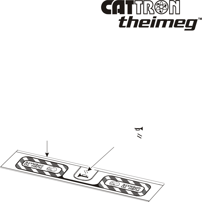
PUSH-TO-OPERATE (PTO) BAR - This bar is a large, full length, spring-return switch located on
top of the unit that is generally used as a safety device that electronically disconnects all motion
switches when it is released, thus stopping motion commands from these switches. The PTO bar is
easily and naturally activated by a convenient and comfortable part of the operator's hand and must be
depressed and maintained before and when any motor or motion command is initiated. It should be
noted that operation of the PTO bar is not required for auxiliary functions, i.e. magnet, lights, etc. For
the exact configuration of the PTO Bar, refer to the custom drawing package supplied with your
controller.
LEVER POD(S) – Up to six lever pods can be installed to your paddle controller and you should refer
to the custom drawing package supplied with your controller for the specific configuration. These
switches may be 11-position, spring return-to-center switches, stepless levers, or dual axis joysticks. For
cranes with stepped output there are five forward (or down) positions, five reverse (or up) positions, and
a center ‘OFF’ (or neutral) position. Each of the five positions, in either direction, selects a different
motor speed. The motor speed increases as the switches are moved away from the center position in
each direction. The crane motors may have fewer than five speeds. For example, cranes with two speed
motors where the third, fourth, and fifth position of the switches operate the motors at the highest speed
which is speed two. As viewed from the operator's position, the crane motor control levers are normally
labeled from left to right; BRIDGE, TROLLEY, and HOIST. If used with a four-motor crane system,
an AUX HOIST control lever is located on the extreme right of the unit.
Locomotive controller lever positions are laid out according to the user’s requirements and you should
refer to the custom drawing package supplied with your controller. Normal locomotive configuration as
viewed left to right from the operator’s position is: THROTTLE, DIRECTION, INDEPENDENT
BRAKE and TRAIN BRAKE.

©03/2007, CATTRON-THEIMEG
™
Section 3, Page 3
Controls and Indicators
, continued.
In addition to the ‘Flag’ style lever paddle (illustrated), different style levers and knobs are available –
refer to ‘Accessories’ in Section 5 of this manual for details. Finally, some controllers are built with a
special two-axis joystick configuration - refer to special operation descriptions and the custom drawing
package supplied with your controller for specific information.
SWITCHES – A momentary push button switch is mounted in the center of the PTO bar, and up to six
switches can be located in front of the PTO bar. Two additional switches may be located below the
lever pods when two finger application is required to prevent the accidental operation of safety critical
functions such as ‘MAGNET’ ‘GRAB’, and ‘VACUUM’. Depending upon the control application,
your controller may be configured with some or all of the following switch types:
• Rotary selector or key switch – mainly used for address selection
• Maintained 2-position toggle – mainly used for auxiliary ‘ON/OFF’ functions (lights, application
of sand, and power up)
• Momentary pushbutton, or toggle – mainly used for non motion functions (horn, brake,
alarm/reset, magnet lift, magnet drop)
TRANSMIT & LOW BATTERY LED – This LED is part of the battery management system and
flashes green when the controller’s Power ON/OFF Switch is set to ‘ON’ and the controller is
transmitting with a good battery installed. The LED flashes red when the battery is low and sounds a
beeper to alert the operator. In addition, a low battery cut-off circuit stops the controller micro-processor
when voltage goes below safe operating range. This is because RF transmitters always operate at full
power over the entire life of the battery.
‘TALKBACK
™
’ LED INDICATOR PANEL – This feature adds two-way data communication to the
CATTRON-THEIMEG
™
Portable Radio Remote Control (PRRC) System when used in conjunction
with the MP96 Series Receiver/Decoder. In the standard PRRC System, all data communication is a
type of one-way communication: namely, control information sent from the operator’s controller to the
receiver/decoder. With TALKBACK
the decoder can communicate back to the controller. Up to
sixteen ON/OFF bits of information can be sent back from the MP96 decoder to the paddle controller.
These bits originate in the MP96 decoder and can be either External Event Inputs or ASO Inputs. The
received bits are displayed on the controller using up to twelve light emitting diodes and/or a Liquid
Crystal Display (LCD).
The decoder will make a TALKBACK
transmission to the controller about once every second. Since
the encoder and decoder are both making transmissions on the same frequency, more airtime is used. In
this instance, timesharing multiple controllers on a single radio channel is not recommended.
Also, the controller’s battery life will be reduced, sometimes significantly, depending on the type of
indicating devices used (digital displays, LED's, etc.). For example, a controller operating on 450 MHz
with a Ni-Cad battery pack will last 10 to 14 hours of continuous operation instead of 36 hours. It
should be noted that Alkaline battery packs are not usable with TALKBACK
systems.

Section 3, Page 4 ©03/2007, CATTRON-THEIMEG
™
Controls and Indicators
, continued.
Your customized controller and PRRC system drawings will show the exact operation of your control
unit. A typical example of TALKBACK
would be its use on radio controlled locomotives.
On a locomotive there is usually a ‘Tree’ of four or five lights used as status indicators that is mounted
on each side of the locomotive. These lights usually show the operator the status of ‘FORWARD’,
‘REVERSE’, ‘THROTTLE’, ‘BRAKES’, and Remote Control System ‘ON’.
Consequently, the PRRC operator must always be close enough to the locomotive to see these lights in
order to determine the status. However, with the TALKBACK
option, status indications are
transmitted back to the controller and displayed with LED's.
This enables the PRRC operator to assume a commanding view of the whole train and its operating area
rather than just the locomotive.
Other fault indications can also be displayed. Examples are: Engine Alarm, Low Air Pressure, High
Engine Water Temperature, Low Engine Oil Pressure, Wheels Slipping, STOP Switch Active, and
Speedometer Digital Readout.
In the case of an overhead crane, the TALKBACK
option enables status and external event
information to be viewed on the controller. Because the PRRC operator is not required to climb the
crane, or view the lights mounted on the crane to determine status, he or she is able to assume a
commanding view of the entire crane operating area.
Some typical display indications for cranes are: Magnet Power ON, Magnet Lift ON, Operator ID Lights
(pitch & catch), Mainline ON, Low Brake Pressure, Direction Verification, Out of Range (with Range
Limiter), ASO Fault, Latched/Unlatched, Aligned (Zone), Hoist Limit Switch, Thermal Trip, and Under
Voltage Trips.
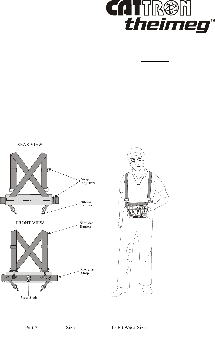
©03/2007, CATTRON-THEIMEG
™
Section 3, Page 5
General Operating Procedure.
NOTES: When using the controller, operators are instructed to wear a factory
approved carrying harness with the controller attached at all times.
If a controller must be left unattended, the STOP Switch (when installed to the
controller) should be depressed and the controller’s POWER ON/OFF switch
set to ‘OFF’. If the POWER ON/OFF switch is a key switch, the key should
also be removed to prevent unauthorized use of the controller (refer to Section
2, Page 7, Item 5 of this manual).
Using a Carrying Harness to support the controller will greatly enhance
operator comfort and operational safety. Two harnesses are available, as
illustrated below in Figures 3-2 and 3-3. Refer to these illustrations for details
and CATTRON-THEIMEG
™
Part Numbers.
Figure 3-2. Standard carrying harness
Standard Carrying Harnesses are available in 2 sizes as follows:
CLN-6096 Small to Large 37.5 - 56 inches
CLN-6096XL Extra Large 48 - 68 inches
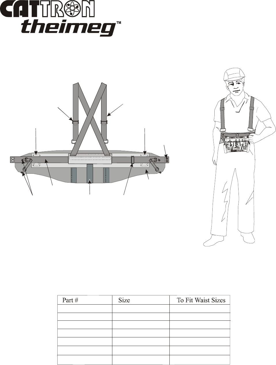
Section 3, Page 6 ©03/2007, CATTRON-THEIMEG
™
General Operating Procedure
, continued.
Figure 3-3. – ‘Low back’ support carrying harness
1. Referring to Figure 3-4 below, assemble and put on the carrying harness, attach the controller to
the harness and adjust for comfortable operation.
Middle Stay Strap Adjuster
Carrying Strap
Anchor Catches
Press Studs
Shoulder Harness
REAR VIEW
Harness Adjuster
Right Hand Side Pull
Left Hand Side Pull
Lower Back and
Abdominal Support
Low Back Support Carrying Harnesses are available as follows:
The Lower Back and Abdominal Support is a lightweight and comfortable device that
acts as a reminder to lift properly. The Side Pulls give you the extra support needed
when lifting. When on break or lunch, you may want to loosen the side pulls, but
D O N OT forg e t t o re- fas ten the m w h e n r e tu rn i n g t o work.
CLN-300902S Small 32 - 36 inches
CLN-300903M Medium 36 - 40 inches
CLN-300904L Large 40 - 44 inches
CLN-300905XL Extra Large 44 - 48 inches
CLN-300906XXL Double Extra Large 48 - 52 inches
CLN-300907XXXL Triple Extra Large 52 - 56 inches
CLN-300901XS Extra Small 28 - 32 inches
NOTE: IF YOU HAVE OR HAVE HAD AN INJURY, CONSULT
YOUR DOCTOR BEFORE USING THIS PRODUCT.
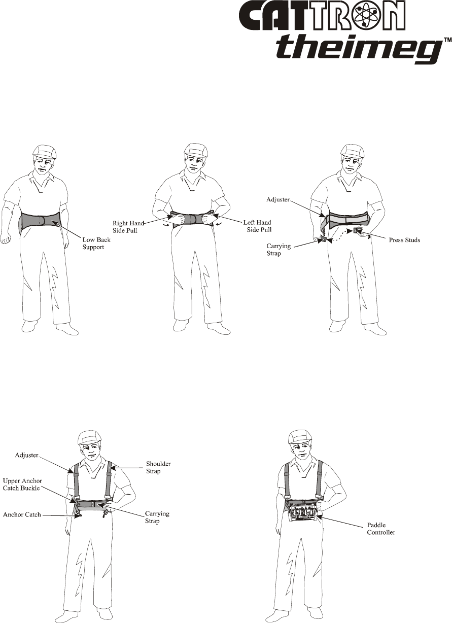
©03/2007, CATTRON-THEIMEG
™
Section 3, Page 7
General Operating Procedure
, continued.
Figure 3-4. Carrying harnesses, assembly and fitting
1-1. Place the Low Back Support around the
body just below the navel, ensuring
the Middle Stay (see Fig 3-3 above)
locates in the center of the low back.
Stretch the right end across the left
and attach firmly.
1-2. Loosen elasticized Side Pulls and
stretch forward as far as possible.
Position the left hand side pull over
the right hand side pull and attach
firmly but comfortably.
1-3. Using Adjuster, lengthen or shorten
Carrying Strap as necessary to provide
a snug fit. Fasten Carrying Strap
around waist using Press Studs.
1-4. Cross the Shoulder Harness Straps at the back
and bring each strap to the front.
Adjust the length of the shoulder straps as
required. Fasten the end catches of the shoulder
straps into the buckles of the Upper Anchor
Catches located on the Carrying Strap
1-5. Fasten the Controller to the Harness
using the four Anchor Catches located
on the Carrying Strap. Re-adjust the
harness as necessary for individual
comfort and preference.
LOW BACK SUPPORT
CARRYING HARNESS ONLY
STANDARD AND LOW BACK SUPPORT
CARRYING HARNESSES
STANDARD AND LOW BACK SUPPORT
CARRYING HARNESSES
STANDARD AND LOW BACK SUPPORT
CARRYING HARNESSES
LOW BACK SUPPORT
CARRYING HARNESS ONLY

Section 3, Page 8 ©03/2007, CATTRON-THEIMEG
™
General Operating Procedure
, continued.
NOTES: Holding the PTO bar down when power is turned on places the controller in
a technical diagnostic mode - refer to Maintenance Instructions (Section 4)
for details. The PTO bar must be up when starting the controller or the
system will not operate.
On some controllers, the side mounted Power ON/OFF Key Switch may be
replaced with a front panel mounted, 2-position maintained toggle switch.
Alternatively, some controllers may have both types of these power ON/OFF
switches installed.
2. Set the controller’s Power ON/OFF Switch(es) to ‘ON’. Observe that the TRANSMIT/LOW
BATTERY LED momentarily flashes yellow and two quick ‘beeps’ are heard. If the LED is red,
replace or recharge the battery pack – refer to Battery Packs and Battery Pack Charging at the
end of this section. When transmitting with a good battery pack, the green TRANSMIT LED
should ‘flash’ rhythmically.
3. When your controller is equipped with the optional ‘Keyless Entry Code’ feature, an assigned
sequence of function switches must be operated within 10 seconds after the Power ON/OFF
Switch is set to ‘ON’. These switches will not operate any functions and the controller power
comes on only after the correct sequence has been entered.
4. When your controller is equipped with an ADDRESS SELECTOR SWITCH, operating this
switch will change the system address, thus allowing a single controller to operate multiple
controlled machines. Extreme caution should be used to insure that you do not select the wrong
machine.
WARNING:
AFTER CHANGING AN ADDRESS OR FREQUENCY SELECTOR SWITCH,
YOU MUST, IN THE FIRST INSTANCE, INSURE THE TARGETED
MACHINE IS UNDER REMOTE CONTROL BEFORE OPERATING ANY
MOTION FUNCTION SWITCH. THIS MAY BE ACCOMPLISHED BY
OPERATING A NON MOTION FUNCTION SWITCH ON THE REMOTE
CONTROLLER SUCH AS A HORN OR LIGHT.
FAILURE TO COMPLY WITH THE ABOVE WARNING MAY RESULT IN
THE UNDESIRED OPERATION OF OTHER EQUIPMENT WHICH, IN
TURN, COULD RESULT IN SERIOUS INJURY OR DEATH TO PERSONNEL
AND DAMAGE TO EQUIPMENT.
©03/2007, CATTRON-THEIMEG
™
Section 3, Page 9
General Operating Procedure
, continued.
5. Place a convenient and comfortable part of either hand on the PUSH TO OPERATE BAR on top
of the controller. This switch must be depressed and maintained before and when any motor or
motion command is initiated.
WARNING:
NEVER DISABLE THE PUSH TO OPERATE (PTO) BAR SWITCH ON YOUR
REMOTE CONTROLLER. FAILURE TO COMPLY WITH THIS WARNING
MAY RESULT IN DAMAGE TO EQUIPMENT, SERIOUS INJURY, OR
DEATH.
6. Operate the motion control lever switches as required, remembering that the levers must be
pulled upward for all REVERSE and UP motions and pushed down for all FORWARD and
DOWN motions. A speed increase is obtained by selecting different, appropriately marked lever
switches. Compass direction labels (N, S, E, & W) may be located next to the appropriate
switches.
7. While commanding a motion with a switch, release the PUSH TO OPERATE BAR without
centering switch. The motion must stop - if this does not happen, set the controller’s Power
ON/OFF Switch to ‘OFF’ and notify your supervisor immediately.
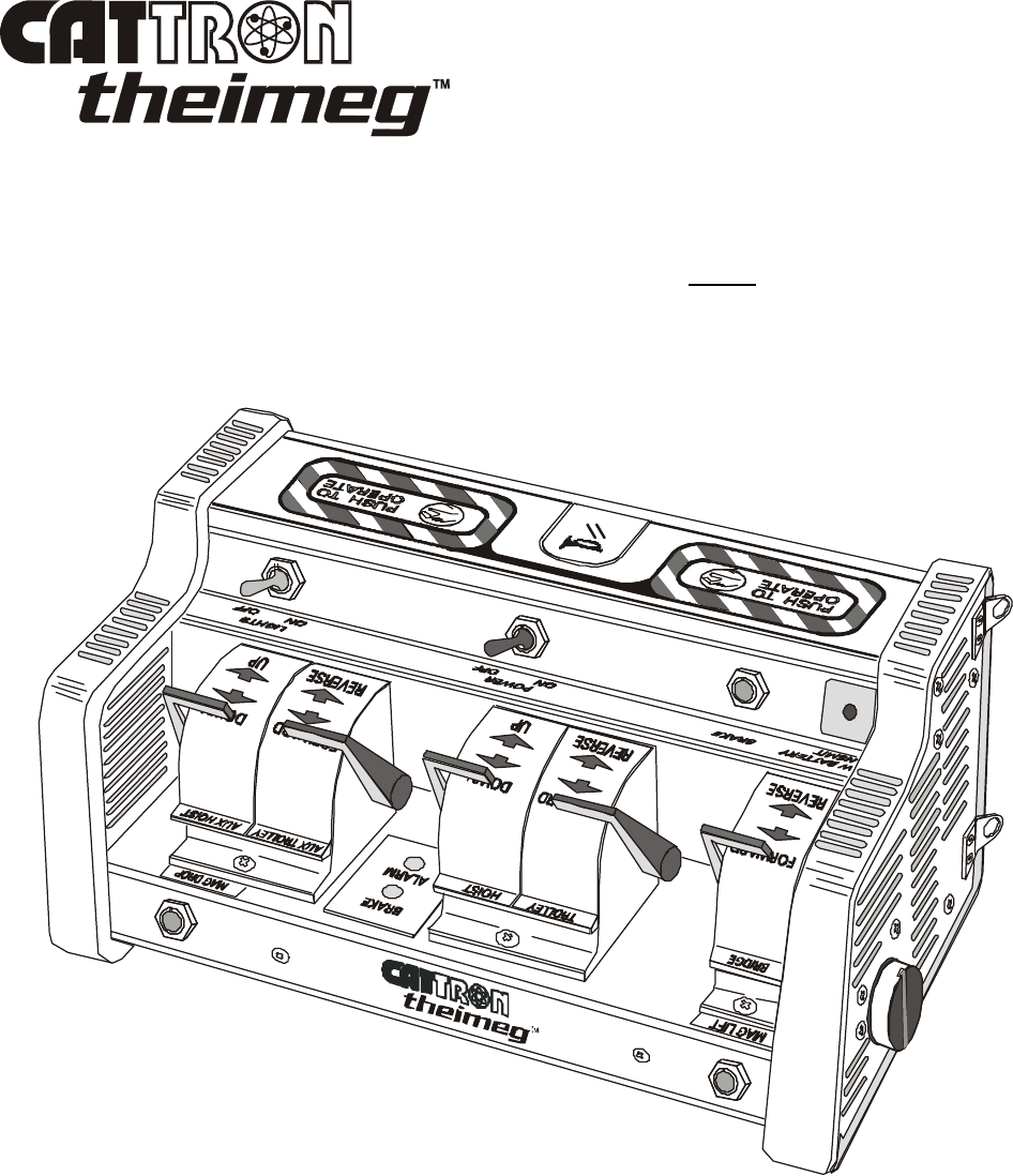
Section 3, Page 10 ©03/2007, CATTRON-THEIMEG
™
TYPICAL CRANE CONTROL FUNCTIONS.
In addition to the controls and indicators described at the beginning of this section, some or all the
control functions described and illustrated below may be applicable to your crane control application.
Unless notified to the contrary, the following Control Functions do not require the PTO Bar to be
pressed to enable their operation.
Figure 3-5. Crane Paddle Controller - Typical configuration

©03/2007, CATTRON-THEIMEG
™
Section 3, Page 11
TYPICAL CRANE CONTROL FUNCTIONS, continued.
1. ALARM, RESET or ALARM/RESET SWITCH. When this momentary pushbutton switch
located in the center of the PTO bar is used as an ALARM, it operates a bell, horn, or other
warning device on the crane. When used as a RESET, this switch resets the mainline contactor
when it has previously been switched or tripped OFF due to a relay failure or overload, thus
allowing power to be supplied to the crane motors. When used as an ALARM/RESET, this
switch operates the ALARM and RESET functions simultaneously.
2. MAGNET, VACUUM, or GRAB. Extra precautions are built into the MAGNET, VACUUM
and GRAB functions to prevent accidental release. Two momentary switches (buttons or
toggles) are normally used for these functions. Accidental operation of the magnet, vacuum or
grab function is minimized by locating these buttons as far as possible from other controls and
requires two fingers to release the load. The Standard Operating Procedure (SOP) for each of
these functions is detailed below; however, this procedure may be changed, depending on the
system application. Please note that any deviation from the SOP will be advised in the drawing
package supplied with your PRC system.
Magnet To Lift, press and hold ‘LIFT’ for one second.
To Drop, press and hold ‘LIFT’, wait for one second, then press and
hold ‘DROP’.
After load is dropped, release ‘LIFT’ first, then release ‘DROP’.
Vacuum To Lift, press and hold ‘VACUUM’ for one second.
To Drop, press and hold ‘VACUUM’, wait for one second, then press
and hold ‘RELEASE’.
After load is dropped, release ‘VACUUM’ first, then release
‘RELEASE’.
Grab To Close, press ‘CLOSE’.
To open, press and hold ‘CLOSE’, then press ‘OPEN’.
After grab is opened, release ‘CLOSE’ first, then release ‘OPEN’.
3. BRAKE SWITCH - This momentary pushbutton or toggle switch is used for manual control of
the crane bridge brakes, usually a parking brake, or the second step of a running brake (first step
normally comes on when motor is made neutral and released when direction is selected). Other
brake functions are available such as PARKING BRAKE RELEASE, COAST, etc.
4. HOOK/GRAB ROTATE SWITCH - This control function is normally a spring return-to-center
(OFF position) toggle switch. It allows a motorized hook or grab to be turned in either a
clockwise (CW) or counter-clockwise (CCW) direction.
5. CRANE LIGHT ON/OFF SWITCH - This maintained toggle switch provides ON/OFF control
of the crane lights. Proper decoder circuitry insures that they remain latched ‘ON’ if required.
Section 3, Page 12 ©03/2007, CATTRON-THEIMEG
™
TYPICAL CRANE CONTROL FUNCTIONS, continued.
6. CRANE SELECT SWITCH - This rotary selector or key switch is used when the controller
operates more than one crane. The switch is used to select the desired crane by changing the
controller's digital address. If switched while the unit is on, the power is switched off
automatically for 10 seconds, then starts up automatically on the new address. All motor and
motion control lever switches on the controller must be neutral during this time.
WARNING:
AFTER CHANGING AN ADDRESS OR FREQUENCY SELECTOR SWITCH,
YOU MUST, IN THE FIRST INSTANCE, INSURE THE TARGETED
MACHINE IS UNDER REMOTE CONTROL BEFORE OPERATING ANY
MOTION FUNCTION SWITCH. THIS MAY BE ACCOMPLISHED BY
OPERATING A NON MOTION FUNCTION SWITCH ON THE REMOTE
CONTROLLER SUCH AS A HORN OR LIGHT.
FAILURE TO COMPLY WITH THE ABOVE WARNING MAY RESULT IN
THE UNDESIRED OPERATION OF OTHER EQUIPMENT WHICH, IN
TURN, COULD RESULT IN SERIOUS INJURY OR DEATH TO PERSONNEL
AND DAMAGE TO EQUIPMENT.
7. OPERATOR RELEASE ‘PITCH AND CATCH’ (Optional) – ‘Pitch and catch’ is the operation
of a single crane by two, three, or four operators on a first-come, first-served basis. This method
provides lock out of the non-commanding operator(s) and allows only one operator at a time. An
example of a two operator ‘pitch and catch’ operation follows:
7-1. The crane is sitting idle and both controllers ‘A’ and ‘B’ are switched OFF.
7-2. Operator ‘A’ turns his/her controller power to ‘ON’ and captures the crane. One of two colored
lights on the crane, energized by auxiliary function relays in the receiver/decoder, indicates
which operator has taken control of the crane. It should be noted that Operator ‘A’ remains in
control even if Operator ‘B’ switches his or her controller power to ‘ON’ and attempts to control
the crane – control access is denied to Operator ‘B’ at this time.
7-3. Operator ‘A’ may release the control of the crane to Operator ‘B’ in one of two ways:
(1) The first way is by pressing the ‘RELEASE’ button on his/her controller (‘pitch’) after
Operator ‘B’ has turned his/her controller power to ‘ON’ and is ready to take control of the
crane. If Controller ‘B’ is transmitting the correct system identification address, Operator
‘B’ is allowed to take control (‘catch’). Operator ‘A’ is now denied control access and
should switch his/her controller power to ‘OFF’.
(2) The second way to transfer control from Operator ‘A’ to Operator ‘B’ is to simply turn
Controller ‘A’ power to ‘OFF’ for a designated period of time (typically 45 seconds). After
this period of no transmission, if Controller ‘B’ power is set to ‘ON’ first, Operator ‘B’ will
capture the crane.
©03/2007, CATTRON-THEIMEG
™
Section 3, Page 13
TYPICAL LOCOMOTIVE CONTROL FUNCTIONS.
In addition to the controls and indicators described at the beginning of this section, some or all the
control functions described and illustrated below may be applicable to your locomotive control
application. Unless notified to the contrary, the following Control Functions do not require the PTO Bar
to be pressed to enable their operation.
Figure 3-6. Locomotive Paddle Controller - Typical Configuration
1. HORN - This momentary push button switch located in the center of the PTO Bar sounds the
horn when pressed.
2. HORN/RESET – This momentary push button switch located in the center of the PTO Bar
sounds the horn and provides the initial ‘RESET’ command to the radio receiver/decoder on the
locomotive. This switch must be activated after powering up the controller, otherwise the
locomotive will not operate. Observe that the horn will sound, thus identifying the locomotive
is under radio control.

Section 3, Page 14 ©03/2007, CATTRON-THEIMEG
™
TYPICAL LOCOMOTIVE CONTROL FUNCTIONS, continued.
3. DIRECTION SWITCH – this maintained 3-position paddle switch controls ‘FORWARD’ and
‘REVERSE’ functions. If the lever is moved to the ‘NEUT’ (neutral or center) position,
direction is disabled.
NOTE: A change in the Locomotive direction will not occur until the throttle is
moved to idle for at least 3-seconds. Attempting to make a change in
direction while the throttle is advanced will cause the throttle to return to
idle. Some systems require that an independent brake is applied for 3
seconds, or a specific brake cylinder pressure has been reached, before a
change in direction can occur.
4. THROTTLE LEVER - Controls the Locomotive throttle. This spring return-to-forward paddle
switch spring returns to the ‘IDLE’ position when released. Note that the PTO Bar must be
pressed to enable this control function. If the PTO Bar is released, the throttle will normally be
returned to ‘IDLE’.
5. INDEPENDENT BRAKE LEVER - Controls the locomotive (independent) brakes using five
maintained lever positions that provide the following braking functions:
‘REL’ - Releases the brakes.
‘LAP' – Holds the independent brakes at the last applied pressure.
‘SA’ - Slow application of the independent brakes.
‘QA’ - Quick application of the independent brakes.
‘EMG’ – Applies train and independent brakes, including the application of sand.
Note that the PTO Bar must be pressed to release the brakes. In most control applications, when
the PTO Bar is released, the independent brakes will be slowly applied.
6. ‘EMG BRAKE’ SWITCH – When set to the ‘EMG BRAKE’ position, this maintained 2-
position toggle switch applies the train and independent brakes, together with the application of
sand.
7. ‘TRAIN’ (AUTOMATIC) BRAKE LEVER - This 3-position switch lever or toggle switch
controls the train brakes and has the following functions:
APPLY (Momentary) – Applies the railcar brakes by reducing the air supply to the train
air line.
HOLD (Maintained) - Seals off the train air line so no further reduction or release will
occur.
REL (Maintained) - Puts air into the train air line to release the railcar brakes.

©03/2007, CATTRON-THEIMEG
™
Section 3, Page 15
TYPICAL LOCOMOTIVE CONTROL FUNCTIONS, continued.
8. SAND – This momentary toggle switch applies sand to the rails in the direction of travel when
held in the ‘SAND’ position.
9. BELL - Sounds the locomotive bell when set to ‘ON’. This function may be programmed to
activate with throttle or direction.
10. HEADLIGHT ‘OFF/DIM/BRIGHT’ – this maintained 3-position switch selects the desired
brightness of the headlight in the direction of travel. In the ‘BRIGHT’ setting, the headlight at
the front of the locomotive illuminates at full power, while the headlight at the rear of the
locomotive or train is dimmed. In the ‘DIM’ position, both front and rear headlights will be
dimmed.
11. UNCOUPLE – Provided there is no tractive pull on the couplers, setting this spring return-to-
center (OFF position) switch to ‘FRONT’ or ‘REAR’ will retract the respective coupling pin
from the front or rear of the locomotive.
12. ALERTER - If equipped with the ‘ALERTER’ option, a switch must be moved by the operator
at least once every 20 seconds (or the amount of time you have programmed) or the controller
beeper will sound. If no action is taken within the next 10 seconds, a function is sent to stop the
locomotive. Moving any switch, including the PTO Bar, will reset the Alerter timeout.
13. OPERATOR RELEASE ‘PITCH AND CATCH’ (Optional) – Locomotive ‘pitch and catch’
allows two operators to swap control to and from each other, based upon which operator should
be commanding movement. Typically, a selector switch mounted on the side of the locomotive
mounted Receiver/decoder enclosure is used to select single or dual operator control.
When the switch is selected for two operators, the Receiver/decoder will not allow the
locomotive to operate unless both transmitters are detected. If at any time, only one transmitter
is detected, the throttle will return to idle and the brakes will set. While in two-operator mode,
the primary controller operator will have control of all functions (i.e. throttle, direction, brakes,
etc.) and be protected by the controller’s internal tilt switch.
The secondary controller operator will maintain control of the ‘HORN’, ‘BELL’, and ‘STOP’
functions, together with other auxiliary functions as designated at the time of system design. He
or she will also be protected by the controller’s internal tilt switch.
For example, should either the primary or secondary operator fall, the Receiver/decoder will stop
the locomotive (typically, setting throttle to idle, applying full independent brakes, sounding the
horn for 10 minutes and, when installed, activating a ‘MAN DOWN’ alarm). It must be noted
that the operator who commands a tilt or ‘STOP’ shutdown must also be the one to
‘RESET’ the shutdown condition.

Section 3, Page 16 ©03/2007, CATTRON-THEIMEG
™
TYPICAL LOCOMOTIVE CONTROL FUNCTIONS, continued.
In a typical locomotive ‘pitch and catch’ application, before a pitch can be made, the following
conditions must be satisfied:
• The Locomotive must be stopped.
• Both controllers must be selecting ‘NEUTRAL’.
• Both controllers must have the same selection on the ‘INDEPENDENT’ and
‘AUTOMATIC’ brake override switch.
• The primary controller operator must depress the ‘OPERATOR RELEASE’
pushbutton.
• The secondary controller operator must depress the ‘OPERATOR ACCEPT’
pushbutton.
As long as the above conditions are met, transfer of control will occur. In addition, if
TALKBACK
™
is available on your control system, a ‘PRIMARY CONTROL’ indicator will
illuminate on the controller in full control.

©03/2007, CATTRON-THEIMEG
™
Section 3, Page 17
Switch Diagnostic Mode.
In this mode the operator can easily check that all function switches (motion and non-motion) are fully
operational.
WARNING:
ELECTRICAL POWER TO THE TARGET CONTROLLED EQUIPMENT
MUST BE COMPLETELY ISOLATED TO PREVENT OPERATION UNDER
REMOTE CONTROL IN THE SWITCH DIAGNOSTIC MODE.
FAILURE TO COMPLY WITH THE ABOVE WARNING MAY RESULT IN
THE UNDESIRED OPERATION OF EQUIPMENT WHICH, IN TURN,
COULD RESULT IN SERIOUS INJURY OR DEATH TO PERSONNEL AND
DAMAGE TO EQUIPMENT.
This is accomplished by first turning off power to the controller using the Power ON/OFF Key and/or
Toggle Switch. Then, place the controller in a tilted (horizontal) position with its battery door face
down. To enable the switch diagnostic mode, re-apply power using the Power ON/OFF Switch(es)
while the controller is in the horizontal position.
This mode of diagnostics activates the beeper when (1) each non-motion (auxiliary) toggle and
pushbutton switch changes state, and (2) when any motion control lever/switch changes state, provided
the PTO Bar is pressed and held down each time the motion lever/switch changes state.
For example, push any one of the auxiliary toggle switches UP and a single ‘beep’ will be heard.
Release the toggle switch and another single ‘beep’ will be heard as the switch spring returns to center.
Repeat this procedure on the remaining non-motion toggle and pushbutton switches in both UP/DOWN
or ON/OFF positions. If the switches are functioning correctly, a ‘beep’ will be heard each time the
switch changes state.
Repeat the above procedure on all motion control levers/switches, remembering to enable these motion
functions by pressing and holding the PTO Bar down when operating a lever/switch. When an enabled
motion lever/switch is functioning correctly, a ‘beep’ will be heard each time the device changes state.
To disable the switch diagnostic mode, simply turn the controller power to ‘OFF’, then re-apply power
to the controller while it is in an upright position.

Section 3, Page 18 ©03/2007, CATTRON-THEIMEG
™
Battery Packs and Battery Pack Charging.
The following battery pack and charging options are available for your controller and may be ordered
from your nearest CATTRON-THEIMEG
™
facility
identified on the back page of this manual.
Alkaline Battery Pack providing 75 hours of continuous operation. This battery pack is not re-
chargeable and should be discarded when exhausted.
Nickel-Cadmium (Ni-Cad) Battery Pack providing approximately 23 hours of continuous operation.
This battery pack is re-chargeable using the CATTRON-THEIMEG
™
70C-0004 Battery Conditioner.
Table 3-1. Battery Pack Options
CATTRON-
THEIMEG
™
PART
NUMBER
TYPE COLOR LIFE
OPERATING
HOURS
RE-CHARGING
TIME
(using 70C-0004
Conditioner/charger)
LIFETIME
CYCLES
C-8096 Ni-Cad
Battery
Pack
Yellow 23* 3-Hours 200+
60C-0023 Alkaline
Battery
Pack
White 75* Do Not Charge 1
* Battery life operating hours are based on continuous transmissions.
Battery Conditioner
- A CATTRON-THEIMEG
™
Battery Conditioner (Part # 70C-0004) is
available for use with CATTRON-THEIMEG
™
C-8096 Ni-Cad Battery packs only.
Battery Pack Replacement
.
When the TRANSMIT/LOW BATTERY LED starts flashing red, this alerts the operator that he or she
has approximately one hour of continuous operation remaining, after which the battery pack must be
replaced or re-charged.
Replace the battery pack as follows:
1. Set the controller’s Power ON/OFF Switch(es) to the ‘OFF’ position.
2. Referring to Figure 3-7 opposite, unlock the battery door by inserting a coin into the slot and
twisting.
3. Open the battery door and lift the battery pack out of the tray.
4. Install a fresh, fully charged battery pack in the controller, making sure the contacts on the
underside of the battery pack locate with their corresponding pick-up contacts in the battery tray.
©03/2007, CATTRON-THEIMEG
™
Section 3, Page 19
Battery Pack Replacement
, continued.
5. Close the battery door and secure by pressing firmly until it snaps into the locked position.
6. Set the controller’s Power ON/OFF Switch(es) to ‘ON’. Observe that the TRANSMIT/LOW
BATTERY LED momentarily flashes yellow and two quick beeps are heard.
When resuming your remote control operation, observe the TRANSMIT/LOW BATTERY LED as you
operate a non-motion function toggle switch such as a horn or light. If this LED is now flashing green,
your controller is fully operational.
Figure 3-7. Battery Pack Replacement.
Section 3, Page 20 ©03/2007, CATTRON-THEIMEG
™
Ni-Cad Battery Pack Conditioning/Charging
(Figure 3-8).
CAUTIONS:
(1) CATTRON-THEIMEG
™
Battery Conditioners are designed for use with
CATTRON-THEIMEG
™
Ni-Cad Battery Packs only.
(2) Battery Packs must be removed or disconnected from Battery Conditioners
within 48-hours of achieving the fully charged state.
Failure to comply with these Cautions may result in equipment and/or battery
damage and will void our warranty.
A Ni-Cad battery pack must be removed from the controller’s battery compartment for external
charging. The Battery Conditioner includes a Mains VAC Adaptor that allows operation from mains
supply voltages between 100 and 240VAC @ 50/60 kHz. Referring to Figure 3-8 opposite, this adaptor
is connected as shown. Similarly, when installing the Ni-Cad Battery Pack to the Battery Conditioner,
refer to Figure 3-8 for the appropriate locating instructions.
The Battery Conditioner automatically conditions the battery pack by first discharging it at 600mA for
2-hours before applying a rapid charge for 1-hour. The conditioner incorporates end of charge detection
circuitry to accurately sense when the battery pack is fully charged. When this condition has been
detected, the conditioner switches to a ‘trickle’ mode that keeps the battery pack fully charged and ready
to use for up to 48-hours. To prevent damage to the battery pack, it should be removed from the
conditioner within 48-hours of achieving a fully charged state.
The CATTRON-THEIMEG
™
Battery Conditioner incorporates an LED that indicates status as follows:
Amber Color – indicates the battery pack is being discharged.
Red Color - indicates the battery pack is being charged at a rapid rate.
Green Color - indicates the battery pack is fully charged and that a ‘trickle’ charge is being
applied to maintain the fully charged state. The battery pack is ready for use and should be
removed from the conditioner within 48-hours.
©03/2007, CATTRON-THEIMEG
™
Section 3, Page 21
Ni-Cad Battery Pack Conditioning/Charging
, continued.
Figure 3-8. Ni -Cad Battery Pack Conditioning – interconnection details.
1. REAR VIEW - CONNECTING THE VAC ADAPTOR
2. FRONT VIEW - INSTALLING THE BATTERY PACK
OUTPUT JACK
FROM MAINS
VAC ADAPTOR
MAINS VAC ADAPTOR
VAC OUTLET
18 VDC INPUT SOCKET
BATTERY CONDITIONER
(PART # 70C-0004)
STATUS
LED
Ni-Cad BATTERY PACK
(PART # C8096)

Section 3, Page 22 ©03/2007, CATTRON-THEIMEG
™
Pre-programmed Frequency Selection.
If your Controller will be used to operate more than one crane, locomotive, or controlled machine, or be
used as a spare controller for multiple remote control systems, up to sixteen selectable frequencies may
have been factory pre-programmed into the controller’s EPROM.
To see if this selectable frequency option applies to your controller, refer to Figure 3-7 above and locate
the serial tag on the inside of the battery door.
If the serial tag indicates a specific frequency in the FREQ line (i.e., 448.1000 MHz) the selectable pre-
programmed frequency option does not apply to your controller.
If the serial tag indicates ‘SELECTABLE’ in the FREQ. line, refer to the frequency chart provided in
your custom drawing package. This frequency chart will specify the pre-programmed channel
frequencies available with your controller.
©03/2007, CATTRON-THEIMEG
™
Section 3, Page 23
Pre-programmed Frequency Selection
, continued.
WARNING:
MORE THAN ONE REMOTE CONTROL SYSTEM MAY BE USED AT,
AROUND, OR NEARBY YOUR OPERATING FACILITY. THEREFORE,
YOU MUST INSURE THE FREQUENCY OF YOUR PADDLE CONTROLLER
EXACTLY MATCHES THE FREQUENCY OF THE DESIRED EQUIPMENT
TO BE OPERATED.
FAILURE TO COMPLY WITH THE ABOVE WARNING MAY RESULT IN
THE UNDESIRED OPERATION OF OTHER EQUIPMENT WHICH, IN
TURN, COULD RESULT IN SERIOUS INJURY OR DEATH TO PERSONNEL
AND DAMAGE TO EQUIPMENT.
To select a pre-programmed frequency, proceed as follows:
1. Record the operating frequency of the intended equipment to be controlled – this may be
found on the front cover of the manual provided with the target receiver/decoder, or on a
serial tag located inside the target receiver/decoder enclosure.
2. Referring to the Frequency Chart supplied with your controller drawing package, locate
the controller frequency that matches the equipment operating frequency recorded in the
previous step, noting its corresponding Channel Address Number which may be from ‘0’
thru ‘7’ or ‘A’ thru ‘F’.
3. Set the controller’s Power ON/OFF Switch(es) to ‘OFF’.
4. Referring to Figure 3-7 above, unlock the battery door by inserting a coin into the slot
and twisting.
5. Open the battery door and remove the battery pack.
6. Referring to Figure 3-9 overleaf, set the four Frequency Channel Selector Switches to
select the Channel Address Number previously noted in step 2., above.
7. Replace the battery pack in the unit, making sure the contacts on the underside of the
battery pack locate with their corresponding pick-up contacts in the battery tray. Close
the battery door and secure by pressing firmly until it snaps into the locked position.
8. Set the controller’s Power ON/OFF Switch(es) to ‘ON’. Observe that the
TRANSMIT/LOW BATTERY LED momentarily flashes yellow and two quick beeps are
heard.
9. Operate a non-motion function such as a horn or light on the target equipment using the
appropriate toggle switch and observe the TRANSMIT/LOW BATTERY LED and the
selected horn or light. If the LED flashes green and the horn or light activates, your
controller is fully operational.
Section 3, Page 24 ©03/2007, CATTRON-THEIMEG
™
Pre-programmed Frequency Selection
, continued.
Figure 3-9. Pre-programmed Frequency Selection

©03/2007, CATTRON-THEIMEG
™
Section 3, Page 25
Pre-programmed Option Selection.
Because each paddle controller has been designed and custom built for a specific remote control
application, the OPTION SELECT SWITCH UNIT (refer to Figure 3-9, opposite) may have been pre-
configured with one of three discrete programming options. It should be noted that the exact switch
configuration will depend upon the firmware selected by your CATTRON-THEIMEG
™
Applications
Engineer at the time your PRRC system was designed. When applicable, a programming option may be
selected from one of the following:
1. Up to 16 frequency only select (factory programmed) – refer to ‘Pre-programmed
Frequency Selection’ in this Section for complete details.
2. 4-frequency select (factory programmed).
3. Up to 16 selection options - each position may be factory programmed with one of the
following:
a) Transmit frequency
b) Transmit address
c) Timesharing pattern
Refer to the specific information in the custom engineered drawing package provided with your
controller to determine the exact configuration of the OPTION SELECT SWITCH UNIT and the
pre-programmed option (if any). When applicable to your controller, specific switch selections
for a given pre-programmed option will be provided.
END OF SECTION

Section 3, Page 26 ©03/2007, CATTRON-THEIMEG
™
This page intentionally left blank

©03/2007, CATTRON-THEIMEG
™
Section 4, Page 1
Section 4 – Maintenance Instructions
CATTRON-THEIMEG
™
Maintenance Philosophy.
Our maintenance philosophy is that inoperative Paddle Controllers are returned as complete units to our
workshops for repair. This is because (a) each controller is customized for a specific control application
which severely restricts component/part interchangeability, (b) the internal circuit board and
microprocessor is extremely sensitive to electrostatic discharge, and (c) internal components are highly
miniaturized and assembled to within very close tolerances. However, CATTRON-THEIMEG
™
will
permit certain preventive and corrective maintenance to be performed without voiding our warranty, as
follows:
Preventive Maintenance is a periodic check of the system to keep it functioning at peak performance.
Preventive maintenance can also help prevent breakdowns and equipment outages by identifying
potential problems before they become real problems.
Corrective Maintenance refers to fixing a problem once it has occurred. The goal of corrective
maintenance is to get the system back on line as quickly as possible with a minimum impact on
operations.
Preventive maintenance.
Preventive maintenance for CATTRON-THEIMEG
™
Paddle Controllers is minimal because they are
extremely durable and reliable units. Preventive maintenance procedures are detailed in the following
sub paragraphs:
Daily Visual Inspection.
Before use, visually inspect the controller for cleanliness, physical damage, and security of external
parts (screws, switches, rubber grips, etc.). CATTRON-THEIMEG
™
emphasizes that regular visual
inspections not only mean quickly locating a source of potential problems, but also may prevent serious
problems from developing later.
Special RF Test
(
CATTRON-THEIMEG
™
trained technicians only).
The special RF test mode is a diagnostic mode that is incorporated in your Paddle Controller. Controller
outputs can be monitored on a spectrum analyzer/communication service monitor set to the same
frequency as the controller. We emphasize this procedure is only for use by customer technicians that
have been trained by ourselves where further details are presented during the CATTRON-THEIMEG
™
training course. For information purposes, the actual RF test procedure is summarized on the next
page:

Section 4, Page 2 ©03/2007, CATTRON-THEIMEG
™
Special RF Test
, continued.
With PTO Bar switch depressed, setting the ON/OFF KEYSWITCH to ‘ON’ will transmit a continuous
beep and the green LED will illuminate continuously. Continually cycling (pressing and releasing) the
PTO bar switch three times will initiate the RF diagnostic sequence (the beep will stop). Further PTO
bar switch cycling will make the controller transmit the following:
CYCLE CONTROLLER TRANSMISSION
4 Maximum Low Frequency (a frequency 2.4 kHz lower than carrier)
5 Q- Sync (center of carrier)
6 Maximum High Frequency (a frequency 2.4 kHz higher than carrier)
7 2 kHz modulating sine wave (tone)
8 1-2-2-1 pattern square wave
Annual Netting Check.
Netting means that the receiver and transmitter of the radio control system are aligned on the same
frequency. It is very important that the receiver is exactly tuned to the frequency required. This check
should be done once a year by a qualified radio technician utilizing calibrated test equipment.
Troubleshooting.
A basic Troubleshooting Guide is provided on page 3 of this section. For safety reasons, when
troubleshooting the Paddle controller, the power supply to the target equipment motors and all motion
functions must be completely isolated to prevent operation under remote control. However, the other
major components of the remote control system (power supply and receiver/decoder) should be fully
operational. The remote control operator should also be located within 500 feet (160+ meters) of the
target receiver/decoder.
©03/2007, CATTRON-THEIMEG
™
Section 4, Page 3
Troubleshooting Guide.
WARNING
ELECTRICAL POWER TO THE TARGET CONTROLLED
EQUIPMENT MUST BE COMPLETELY ISOLATED TO
PREVENT OPERATION UNDER REMOTE CONTROL
IN THE SWITCH DIAGNOSTIC MODE.
FAILURE TO COMPLY WITH THIS WARNING MAY RESULT
IN THE UNDESIRED OPERATION OF EQUIPMENT
WHICH, IN TURN, COULD RESULT IN SERIOUS INJURY
OR DEATH TO PERSONNEL AND DAMAGE TO
EQUIPMENT.

Section 4, Page 4 ©03/2007, CATTRON-THEIMEG
™
Corrective maintenance.
Corrective maintenance for the Paddle Controller is restricted to replacing the Battery Pack, Address
Code Plug, Paddle Levers and, when installed, the External Antenna. Refer to the Replacement
Procedures below when removing and replacing items. Having replaced an item, and before placing
the Paddle Controller into operational service, carry out a Functional Check as follows:
Functional Check.
1. Set the controller’s Power ON/OFF Switch(es) to ‘ON’. Observe that the
TRANSMIT/LOW BATTERY LED momentarily flashes yellow and two quick ‘beeps’
are heard.
2. Operate a non-motion function such as a horn or light on the target equipment using the
appropriate toggle switch and observe the TRANSMIT/LOW BATTERY LED which
should flash green.
3. Set the controller’s Power ON/OFF Switch(es) to ‘OFF’.
4. Operate the controller in Switch Diagnostic Mode (refer to Section 3 for procedure),
insuring all toggle, pushbutton, and paddle lever function switches are fully operational.
Replacement Items.
Replacement items and accessories for your controller may be ordered direct from CATTRON-
THEIMEG
™
. To order replacement items, refer to Section 5 of this manual for details and part
numbers.
Replacement Procedures.
Battery Pack Replacement
.
To replace the battery pack, proceed as follows:
1. Set the controller’s Power ON/OFF Switch(es) to ‘OFF’.
2. Referring to Figure 4-1 opposite, unlock the battery door by inserting a coin into the slot
and twisting.
3. Open the battery door and lift the battery pack out of the tray.
4. Install a fresh or fully charged battery pack in the unit, making sure the contacts on the
underside of the battery pack locate with their corresponding pick-up contacts in the
battery tray.
5. Close the battery door and secure by pressing firmly until it snaps into the locked
position.
6. Carry out a Functional Check on the controller – refer to the above paragraph for details.
©03/2007, CATTRON-THEIMEG
™
Section 4, Page 5
Battery Pack Replacement
, continued.
Figure 4-1. Battery Pack Replacement.
Address Code Plug Replacement.
Each CATTRON-THEIMEG
™
Paddle Controller is equipped with a code plug. This code plug sets the
address of the controller which should always match the address of the target receiver/decoder. When a
command is received by the receiver/decoder, the address of the controller sending the signal is checked
against the address of the receiver/decoder. If the addresses do not match, the signal is ignored and an
error message is displayed on the receiver/decoder. For safety reasons, it is important that no two
controllers at a location use the same address settings. This could cause operation of undesired
equipment resulting in damage to equipment and/or personal injury.
While the factory address setting will be adequate for most users, there may be conditions where it is
necessary to change the address code. Such conditions include the use of a spare controller, or when
your controller will be used to operate more than one crane, locomotive, or controlled machine. Before
making any change in the address code setting, you will be required to identify the address code of the
target receiver/decoder.
The code assigned to the receiver/decoder at the factory is found on a serial tag located inside the target
receiver/decoder. For information on setting the address code for your receiver/decoder, refer to the
documentation provided with the receiver/decoder.

Section 4, Page 6 ©03/2007, CATTRON-THEIMEG
™
Address Code Plug Replacement
, continued.
WARNINGS:
UNCODED ADDRESS PLUG(S) SHALL BE PROGRAMMED WITH THE
SAME ADDRESS CODE AS SET IN THE TARGET RECEIVER/DECODER.
IT SHOULD BE FULLY UNDERSTOOD THAT CATTRON-THEIMEG
™
SHALL NOT BE HELD LIABLE FOR PERSONAL INJURY, DEATH,
EQUIPMENT OR PROPERTY DAMAGE ARISING FROM DUPLICATED,
INCORRECTLY PROGRAMMED OR INCORRECT CODE PLUG USAGE.
IT IS YOUR RESPONSIBILITY TO ESTABLISH A PROCEDURE THAT
INSURES ONLY THE CODE PLUG CONFIGURED FOR A PARTICULAR
ADDRESS IS INSTALLED IN EQUIPMENT DESIGNED TO OPERATE ON
THE SAME ADDRESS. NEVER PUT MORE THAN ONE CONTROLLER
INTO OPERATION ON THE SAME ADDRESS AT ANY GIVEN TIME.
CATTRON-THEIMEG
™
STRONGLY ADVISES YOU TO IMPLEMENT AND
REGULARLY UPDATE A REGISTER OF INDIVIDUAL ADDRESSES AND
OPERATING FREQUENCIES ASSIGNED TO EACH PORTABLE RADIO
REMOTE CONTROL (PRRC) SYSTEM LOCATED AT YOUR OPERATING
FACILITY. IN ADDITION, ANY SPARE CODE PLUGS, OR CODE PLUGS
INSTALLED IN EQUIPMENT THAT ARE CONFIGURED FOR THE SAME
ADDRESS OF EQUIPMENT THAT IS IN SERVICE, MUST BE HELD UNDER
LOCK AND KEY BY A DESIGNATED SUPERVISOR.
FAILURE TO COMPLY WITH THESE WARNINGS MAY RESULT IN
OPERATION OF UNDESIRED EQUIPMENT WHICH IN TURN COULD
RESULT IN PERSONAL INJURY OR DEATH TO PERSONNEL AND
DAMAGE TO EQUIPMENT.
CATTRON-THEIMEG
™
sets the address code of all paddle controllers before they leave the factory. If
the code must be changed, a new code plug with the new address code must be obtained from
CATTRON-THEIMEG
™
. In some circumstances CATTRON-THEIMEG
™
may provide blank, or
unset, code plugs. An unset code plug must have a code set prior to installing in the decoder. This is
described in the procedure below. Installing an unset code plug in the controller will prevent the
controller from operating.
To replace the code plug for your Paddle Controller, proceed as follows:
1. Set the controller’s Power ON/OFF Switch(es) to ‘OFF’.
2. Record the address code of the intended equipment to be controlled – this may be found
on the front cover of the manual provided with the target receiver/decoder, or on a serial
tag located inside the target receiver/decoder enclosure.
3. Referring to Figure 4-1 above, unlock the battery door by inserting a coin into the slot
and twisting.
4. Open the battery door and lift the battery pack out of the tray.
©03/2007, CATTRON-THEIMEG
™
Section 4, Page 7
Address Code Plug Replacement
, continued.
5. Referring to Figure 4-2 below, using a pair of small flat nosed pliers, remove the existing
‘set’ code plug by pulling it straight up and away from its battery compartment location.
We recommend you: (1) tag the removed code plug with the serial number of the
controller, and (2) deposit the code plug in a safe place under lock and key.
Figure 4-2. Code Plug Location.
BATTERY
COMPARTMENT
‘SET’ CODE
PLUG
Section 4, Page 8 ©03/2007, CATTRON-THEIMEG
™
Address Code Plug Replacement
, continued.
6. If the new code plug is blank (unset), set the new address code previously recorded in
Step 2. To set the code, pins 2 through 8 must be cut in a specific pattern. Figure 4-3
below shows all possible address codes for the code plug. For example, to set the code
plug to Address Code 14, pins 4, and 6 must be cut. DO NOT cut Pins 1, 9 and 10.
Figure 4-3. Code plug settings.
©03/2007, CATTRON-THEIMEG
™
Section 4, Page 9
Address Code Plug Replacement,
continued.
7. Write the newly set address code on the side of the code plug using a permanent marker.
8. Carefully install the new code plug, making sure the spot (Pin 1) is positioned as shown
in Figure 4-2, above.
9. Referring to Figure 4-1 above, replace the battery pack in the unit, making sure the
contacts on the underside of the battery pack locate with their corresponding pick-up
contacts in the battery tray.
10. Close the battery door and secure by pressing firmly until it snaps into the locked
position.
11. Carry out a Functional Check on the controller – refer to page 4 of this Section for
details.
Paddle Lever Replacement
, (Figure 4-4).
1. To replace a Paddle Lever, remove Screw (1) using a 6/32" hexagonal key and withdraw
Lever (2) from Shaft (3).
2. Install a new Lever (2) to the Shaft (3) and secure using Screw (1).
Figure 4-4. Lever Replacement.
External Antenna Replacement
, (Figure 4-5).
1. Remove the External Antenna (1) by pushing down and unscrewing the BNC connector
(2) half-a-turn in a counter-clockwise direction from its connector socket (3) located on
the lower front plate of the controller.
2. The new Antenna (1) is simply installed by screwing the BNC connector (2) clockwise
until it ‘clicks’ into the connector socket (3) located on the lower front plate of the
controller.
1. SCREW
2. LEVER
3. SHAFT
1
2
3
Section 4, Page 10 ©03/2007, CATTRON-THEIMEG
™
External Antenna Replacement
, continued.
Figure 4-5. External Antenna Replacement.
1
2
3
END OF SECTION

©03/2007, CATTRON-THEIMEG
™
Section 5, Page 1
Section 5 – Replacement Items and Accessories
Notable differences between Paddle Controllers will include the quantity, type, and placement of toggle,
paddle, and pushbutton switches. For an individual controller’s exact switch and indicator
configuration, including quantities and part numbers, you should refer to the schematic drawing
originally supplied with the paddle controller.
Note: Replacement items identified in Figure 5-1 overleaf should only be installed by
approved customer technicians who have attended the CATTRON-THEIMEG
™
Technician Training Course.
Referring to the illustration overleaf (Figure 5-1):
• Two types of Pushbutton Switch Assemblies are available - cross refer to Table 5-1 below
• Toggle Switch Assemblies are supplied in a variety of configurations - cross refer to Table 5-2
below.
• Items 1 through 29 are common to most paddle controllers - cross refer to Table 5-3.
Table 5-1. Pushbutton Switch Assemblies
COMPONENT DESCRIPTION CATTRON-THEIMEG
™
PART NUMBER
RED PUSHBUTTON 40C-0308
GRAY PUSHBUTTON 40C-0308GRY
Table 5-2. Toggle Switch Assemblies
COMPONENT DESCRIPTION SWITCH BODY*
IDENTIFIER CATTRON-THEIMEG
™
PART NUMBER
ON-OFF-ON 12TW1-1 40C-0112
ON-OFF-ON LKG. 12TW1-1A 40C-0356
ON-OFF 12TW1-3 40C-0005
ON-OFF LKG. 12TW1-3D 40C-0337
ON-OFF-(ON) 12TW1-5 40C-0113
ON-OFF-(LIFT ON) 12TW1-5N 40C-0315
(ON) OFF (ON) 12TW1-7 40C-0111
(LIFT ON) OFF (LIFT ON) 12TW1-7E 40C-0347
OFF (ON) 12TW1-8 40C-0170
OFF (LIFT ON) 12TW1-8F 40C-0303
* The identifier number is engraved on the switch body
Section 5, Page 2 ©03/2007, CATTRON-THEIMEG
™
1
23
F
i
g
u
r
e
5
-
1
.
E
x
p
l
o
d
e
d
V
i
e
w
9
9B
9
A
6
7
8
1
0
5
4
2
1
1
1
2
1
1
24
25
17
26 27
2
8
29
16
16
14D
14A
14B
14
14C
15E
15
15A
1
5B
15C
15D
19
13
18
2
0
2
1
2
2
2
3
P
U
S
H
B
U
T
T
O
N
S
W
I
T
C
H
A
S
S
E
M
B
L
I
E
S
(
s
e
e
T
a
b
l
e
2
)
T
O
G
G
L
E
S
W
I
T
C
H
A
S
S
E
M
B
L
I
E
S
(
s
e
e
T
a
b
l
e
3
)

©03/2007, CATTRON-THEIMEG
™
Section 5, Page 3
Table 5-3. Common items
FIGURE
5-1,
ITEM
NUMBER
COMPONENT DESCRIPTION QUANTITY
PER
ASSEMBLY
CATTRON-
THEIMEG
™
PART
NUMBER
1 Screw, Truss Head, Phillips, 8-32 x 5/8" 20 03C-0094
2 Screw, Truss Head, Phillips, 8-32 x 1" 2 03C-0099
3 RH Endcap Assembly, with Sonalert 1 01C-0126
- … Gasket, RH Endcap 1 32C-0092R
4 Washer/Spacer 8 04C-0027
5 Bracket Ring for carrying harness 4 07-83585B01
6 Front Housing, 3-Motor 1 15C-0115F
- Front Housing, 4-Motor* 1 15C-0115F4
7 Battery Housing, complete 1 01C-0115R-01
8 Encoder Board** 1 E840/M840P Series
9 PTO Bar Assembly, c/w Tab & Label 1 01C-0276WA-01
9A ... Tab, PTO 1 15C-0114A-01
9B ... Label 1 54C-0107WA
10 LH Endcap Assembly 1 01C-0125
- … Gasket, LH Endcap 1 32C-0092L
11 Switch, Keylock with Keynob and wires 1 01C-40C-0369K
12 Key, complete with Hexagonal Knob 1 55C-0369K
13 Lever Switch Assembly RH As Required CPA-0274
14 Lever Switch Assembly LH As Required CPA-0275
14A ... LH Side Plate, c/w Standoff 1 15C-0057
14B ... Side Plate, Blank, RH or LH 1 15C-0059
14C ... Screw, Truss Hd, Phillips, 4-40 x 3/8" 4 03C-0096
14D ... Housing, Single 1 15C-01125S
15 Lever Switch Assembly, Dual As Required CPA-0276
15A ... RH Side Plate, c/w Standoff 1 15C-0058
15B ... LH Side Plate, c/w Standoff 1 15C-0057
15C ... Screw, Flat Hd, Phillips, 4-40 x 3/8" 4 03C-0096
15D ... Gear Cap 1 15C-135-3274
15E ... Housing, Dual 1 15C-0112D
16 Screw, Truss Head, Phillips, 6-32 x 3/8" As Required 03C-0095
Section 5, Page 4 ©03/2007, CATTRON-THEIMEG
™
Table 5-3. Common items, continued
FIGURE
5-1,
ITEM
NUMBER
COMPONENT DESCRIPTION QUANTITY
PER
ASSEMBLY
CATTRON-
THEIMEG™
PART NUMBER
17 Lever, Left Hand As Required 36-83735D03-LEX
18 Lever, Right Hand As Required 36-83735D01-LEX
19 Screw, Hex, Set, 6-32 x 0.5", SS, Lever As Required 03-83641C01
20 Screw, Truss Head, Phillips, 6-32 x 1/4" As Required 03C-0100
21 LED, Non-diffused, Red/Green 1 40C-0227
22 Battery Cover, with Gasket 1 01C-0278-01
23 Bottom Housing, 3 & 4-Paddle 1 15C-0115B
24 Antenna, 402-470MHz** 1 CAE-6007SYN
25 Screw, Truss Head, Phillips, 4-40 x 1/4" 2 03C-0098
26 Nut, Hex, Encl Top, 15-32 As Required 02C-0011
27 Washer, Sealing, 15/32-32, Switch
Panel As Required 04C-0047
28 Gasket, Single As Required 32C-0032
29 Gasket, Dual As Required 32C-0033
* Alternative
** see schematic drawing originally supplied with controller for correct part number.

©03/2007, CATTRON-THEIMEG
™
Section 5, Page 5
Consumable Items and Optional Accessories.
Consumable Items and Optional Accessories are listed in Table 5-4 below and illustrated on the
following pages.
Table 5-4. Consumable Items and Optional Accessories
Item
Number
CATTRON-
THEIMEG
™
Part Number
Order
Quantity
Item Description
1 60C-0023 1 Battery pack, Alkaline, 12.5V, non-rechargeable
2 C-8096 1 Battery pack, Ni-Cad, re-chargeable, 12.5V, 850 mAH
3 70C-0004 1 Battery Conditioner, 100-240 VAC input
4 CLN-6095 1 Carrying Harness, Standard, small
* CLN-6096 - Carrying Harness, Standard, large
* CLN-6096XL - Carrying Harness, Standard, extra large
5 CLN-300901XS 1 Carrying Harness, Low Back Support, extra small
* CLN-300902S - Carrying Harness, Low Back Support, small
* CLN-300903M - Carrying Harness, Low Back Support, medium
* CLN-300904L - Carrying Harness, Low Back Support, large
* CLN-300905XL - Carrying Harness, Low Back Support, extra large
* CLN-300906XXL
- Carrying Harness, Low Back Support, double extra
large
* CLN-
300907XXXL - Carrying Harness, Low Back Support, triple extra
large
6 06C-0232 1 Code Plug, Unprogrammed
7 06C-0232P 1 Code Plug, Programmed
8 36C-0066 1 Custom Lever, Right Hand, Blank, threaded
9 36C-0067 1 Custom Lever, Left Hand, Blank, threaded
10 36C-0073-O 1 Knob, Oval, for Items 8 and 9 above
11 36C-0073-S 1 Knob, Square, for Items 8 and 9 above
12 36C-0073-C 1 Knob, Cylindrical, for Items 8 and 9 above
13 36C-0073-H 1 Knob, Hexagonal, for Items 8 and 9 above
* = alternative
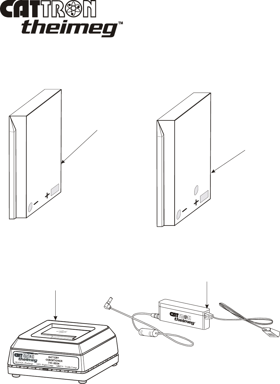
Section 5, Page 6 ©03/2007, CATTRON-THEIMEG
™
Consumable Items and Optional Accessories
, continued.
Item 1 – Part Number 60C-0023 Item 2 – Part Number C-8096
Item 3 – Part Number 70C-0004
MULTI-VOLTAGE ADAPTER
BATTERY PACK CONDITIONER
PART NUMBER 70C-0004
NON RE-CHARGEABLE
ALKALINE BATTERY PACK
(white color)
RE-CHARGEABLE
NI-CAD BATTERY PACK
(yellow color)
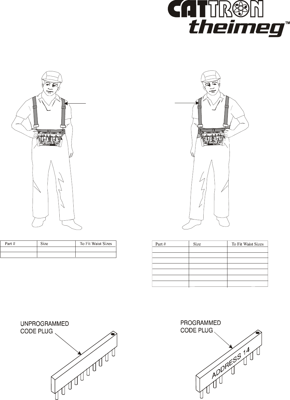
©03/2007, CATTRON-THEIMEG
™
Section 5, Page 7
Consumable Items and Optional Accessories
, continued.
Item 4 – Part Number CLN-609Series Item 5 – Part Number CLN-3009Series
Item 6 – Part Number 06C-0232 Item 7 – Part Number 06C-0232P
STANDARD
CARRYING
HARNESS
LOW BACK
SUPPORT
CARRYING
HARNESS
Standard Carrying Harnesses are available in 2 sizes as follows:
CLN-6096 Small to Large 37.5 - 56 inches
CLN-6096XL Extra Large 48 - 68 inches
Low Back Support Carrying Harnesses are available as follows:
CLN-300902S Small 32 - 36 inches
CLN-300903M Medium 36 - 40 inches
CLN-300904L Large 40 - 44 inches
CLN-300905XL Extra Large 44 - 48 inches
CLN-300906XXL Double Extra Large 48 - 52 inches
CLN-300907XXXL Triple Extra Large 52 - 56 inches
CLN-300901XS Extra Small 28 - 32 inches
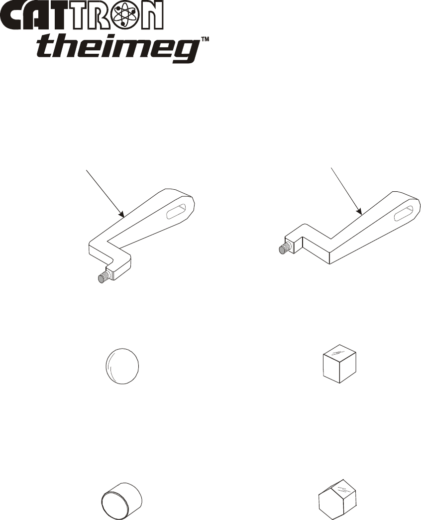
Section 5, Page 8 ©03/2007, CATTRON-THEIMEG
™
Consumable Items and Optional Accessories
, continued.
Item 8 – Part Number 36C-0066 Item 9 – Part Number 36C-0067
Item 10 – Part Number 36C-0073-O Item 11 – Part Number 36C-0073-S
Item 12 – Part Number 36C-0073-C Item 13 – Part Number 36C-0073-H
END OF SECTION
CUSTOM RIGHT
HAND LEVER
CUSTOM LEFT
HAND LEVER
OVAL
KNOB
SQUARE
KNOB
CYLINDRICAL
KNOB
HEXAGONAL
KNOB

03/2007, CATTRON-THEIMEG
™
Index i
Index
A
Accessories ..................................... 5-5
Address code ................................... 2-1
Applications .................................... 1-3
Automatic safety override ............... 2-1
B
Battery Pack Conditioner ...... 3-18, 5-2
Battery door ................................. 3-18
Battery pack conditioning ............ 3-20
Battery pack options ..............1-2, 3-18
Battery pack replacement....... 3-18, 4-4
Battery Saver ...................................1-2
C
Carrying harnesses ................ 3-5 - 3-7
Code plug replacement .................... 4-5
Controls and indicators ................... 3-1
Corrective maintenance .................. 4-4
Crane Control Functions (typical) ...3-10
Custom paddle levers & knobs ........ 5-7
D
Data error checking ........................ 2-2
F
Frequency options .......................... 1-3
Frequency selection .................... 3-22
Frequently asked questions.............. 1-3
Functional check ............................ 4-4
G
General operating procedure .......... 3-5
I
Intelligent digital message protocol 2-1
L
Lever switch placement ...................1-2
Lever replacement ........................... 4-9
List of abbreviations ......................... iii
Locomotive Control Functions .... 3-13
M
Maintenance instructions ............... 4-1
Maintenance philosophy ................ 4-1
N
Netting check ............................... 4-2
Notable performance & safety
Features ................................ 1-2
O
Operate (OPR) relay .................... .. 2-1
Operating frequency ..................... .. 1-3
Operating instructions .................. .. 3-1
Optional accessories ..................... .. 5-3
Overview, remote control systems .. 1-7

Index ii ©03/2007, CATTRON-THEIMEG
™
Index
P
Paddle switch placement ................ 1-2
Power On Self Test (POST) ........... 1-2
Power ON/OFF switch ............. 3-1, 3-2
Preventive maintenance ................. 4-2
Push To Operate bar switch...... 2-2, 3-2
R
Radio control operator’s duties:
General Equipment ................. 2-4
EOT Crane ............................ 2-8
Locomotive ........................... 2-12
Replacement items ................... 4-4, 5-1
Replacements:
Battery pack ............................ 4-4
Address code plug ................... 4-5
Paddle lever ............................ 4-9
External Antenna .................... 4-9
S
Safety considerations ................... 2-1
Safety & security features ............ 2-1
Side mounted levers ............... 1-2, 3-2
Standard specifications ................. 1-5
Switches ................................. 3-2, 3-3
Switch diagnostic mode ................ 3-17
T
TALKBACK
TM
option .................. 3-3
Technical Abbreviations ................. iii
Transmit/Low Battery indicator .... 3-3
Troubleshooting guide .................. 4-3
Typical method of operation ........ 2-2

03/2007, CATTRON-THEIMEG
™
Cranesafety – page 1
RECOMMENDED SAFETY RULES
FOR PORTABLE REMOTE CONTROLLED (PRC) CRANES
For the purpose of these rules, Portable Remote Control or PRC refers to Radio Frequency (RF)
Controls. The information contained herein is based on data gathered from various users of portable
remote control crane systems. We emphasize that the recommendations contained herein are not
intended to supersede the rules or regulations of our customers, or the rules and regulations of
any applicable local, state, or federal government organizations. It must be fully understood that
the recommendations contained herein are provided solely for your consideration and possible
adoption.
TABLE OF CONTENTS
SECTION TITLE PAGE
1 Preface 1
2 Operator Safety Basics 2
2-1 Area Inspection 2
2-2 Crane Inspection (mechanical & structural) 2
2-3 Operational Safety Check 3
3 Persons Authorized to Operate Remote Controlled cranes 3
4 Training Check List for Operation of Remote Controlled cranes 3
5 Operating Area for Remote Controlled Cranes 4
6 The Hand-held Portable Remote Controller 4
7 Operating the Remote Controlled Crane 5
8 Boarding the Remote Controlled Crane 6
9 On Board the Remote Controlled Crane 6
10 Remote Controlled Crane under Repair 7
11 The Condition of the Remote Controlled Crane 8
1. PREFACE.
1-1. Electric Overhead Traveling (EOT) Cranes typically operate in three motions. They are large,
bulky pieces of equipment that handle heavy loads efficiently at comparatively high speeds.
Frequently, they are operated in restricted areas where workmen are engaged in various tasks on
the floor below. Under these conditions crane operators using Portable Remote Control (PRC)
must take great care, and workmen must be constantly on the alert if accidents are to be avoided.
1-2. The following guidelines have been carefully assembled and are promoted to indicate just how
important your careful and thoughtful actions are in helping to protect you and your fellow
workers from harm, and also to prevent equipment damage.
1-3. These guidelines cover cranes when they are operational in Portable Remote Control (PRC)
mode by Radio Frequency. If a crane is operated from cab or pendant control, the PRC system’s
controller(s) should be completely isolated by removing the battery and held under lock and key.
1-4. A routine pre-shift inspection of the crane takes a lot less time than repairing a crane suffering
from a major problem. In addition, such pre-shift inspections are to be considered as ‘safety
basics’ which are an important part of a crane operator’s duties.

Cranesafety – page 2 03/2007, CATTRON-THEIMEG
™
2. OPERATOR SAFETY BASICS. Before starting your shift as the crane operator, you should
make sure the crane has a current inspection certificate and that qualified personnel have carried
out the following inspections and checks. If any item below does not pass inspection, you should
notify your supervisor immediately. In many cases, the problem will need to be fixed before you
are allowed to operate the crane. In addition, did you realize that the person now reading these
instructions is primarily responsible for his or her own health and safety?
2-1 Area Inspection.
• Take a good look around the work area for any obstructions.
• Check that the rails are intact and not bent or damaged.
• Make sure there are no oil or brake fluid leaks on the area below where the crane travels.
• Make sure rail stops are present, physically secure, and free of damage at the end of all crane
rails.
• Check that walkways are sturdy and have handrails. Ladders are not to be loose and all rungs
are to be in place.
2-2. Crane Inspection (mechanical & structural).
• Make sure all moving machinery has protective guards installed over moving parts.
• Make sure all bridge and trolley rail stops are welded or bolted in position with no evidence
of damage from bridge or trolley impact.
• Check for proper fluid levels and make sure all grease fittings are lubricated to manufacturer
recommendations.
• Check for broken welds and cracks in the bridge structure.
• Check for wheel damage, broken welds on the frame, and drum damage.
• Check the wheels for flange wear, cracks, holes, or visible signs of bearing damage.
• Make sure wire rope drums show proper wire rope lay; for example, each wire rope must lay
in its own groove. This does not mean in the non-grooved area in the center of the drum.
• Make sure wire rope size is correct for the sheaves. Look for either oversized or undersized
rope that will not lay in the sheaves correctly. Make sure the sheaves show no evidence of
rope corrugation and have the proper wall thickness.
• Look for any type of bluing on the brake drums which indicates excessive heat. Make sure
there are no protruding rivets from the brake shoes. Examine the shoes for glazing.
• Look for carbon dust around the inspection covers of electric motors. Smell for any type of
burning smells. Check for any type of burning on electrical covers. Make sure all protective
covers are installed.
• Check the festoon system for proper connections and inspect all hooks connecting the
festoon to the holding wire.
• Load bearing parts such as blocks and hooks shall have no signs of damage and be in perfect
working order.

03/2007, CATTRON-THEIMEG
™
Cranesafety – page 3
2-3. Operational Safety Check. As a crane operator, you should satisfy yourself of the following.
If any item below does not meet the checklist criteria, you shall immediately notify your
supervisor. In many cases, the problem will need to be fixed before you are allowed to operate
the crane. Remember that the person now reading these instructions is primarily responsible for
his or her own health and safety!
• Horns, buzzers and all other warning devices shall be in working order.
• All controls shall be in good working order.
• STOP Buttons (when equipped) shall be in working order.
• The load brakes shall hold the load safely at all times. The only way to ensure this is through
a load test and inspection.
• The ‘raise’ and ‘lower’ limit switches shall work correctly to help prevent two-blocking and
accidental floor contact.
3. PERSONS AUTHORIZED TO OPERATE REMOTE CONTROLLED CRANES.
• Only properly trained employees who have been designated by management shall be
permitted to operate the crane.
• Both the operator and management shall insure the correct controller to operate the crane is
selected and that any spare equipment capable of controlling the crane is completely isolated
and held under lock and key.
• The crane shall not be operated by personnel who cannot read and understand the signs,
notices and operating instructions.
• The crane shall not be operated by personnel with seriously defective eyesight or hearing,
personnel under the influence of drugs or alcohol that will impair judgment, or personnel
who may be suffering from a disease which may cause physical failure.
4. TRAINING CHECKLIST FOR OPERATORS OF REMOTE CONTROLLED CRANES.
As a minimum, Portable Remote Control Operators shall:
• have knowledge of hazards inherent to crane operation.
• have knowledge of safety guidelines for portable remote controlled cranes.
• have the ability to judge distance to stationary objects.
• have knowledge of the portable remote control system controller’s operation.
• have performed limit switch test procedure before operating the crane.
• have performed hoist, trolley and bridge brake test procedure before operating the crane.
• have instructions as to plugging of crane motions when and where authorized.
• observe signal lights on crane.
• avoid striking any obstructions.
• check for proper clearance of lifts or hooks before moving bridge or trolley.
• properly store the portable remote controller when not in use.
• know how to properly transfer the portable remote controller to another person.
• report unsafe or unusual operating conditions.
• use caution in approaching bridge or trolley end-stops.
• know the crane’s capacity.
• keep body clear of lifts, avoiding ‘pinch’ points.
• Inspect cables and hooks.

Cranesafety – page 4 03/2007, CATTRON-THEIMEG
™
5. THE OPERATING AREA FOR THE REMOTE CONTROLLED CRANE.
• Unobstructed aisles between equipment, stock, etc. shall be maintained for the PRC crane
operator's movement. These aisles should be a minimum of 3 feet wide (1m) or per local
regulations.
• PRC crane operators shall always position themselves in a safe location with the best view of
the crane they are controlling and never operate the crane blindly. They shall always keep
the crane and load in sight, staying as close as practical to the crane load while maintaining a
safe harms-way distance. Operators shall never position themselves or others underneath the
load or in a ‘pinch’ point.
6. THE HAND-HELD PORTABLE REMOTE CONTROLLER.
• Typically, the portable remote controller incorporates a Push-To-Operate (PTO) bar or
START button, and its motion switches are spring return to OFF. The PTO bar acts as a
guard for these switches to prevent movement of the crane if one of the switches is
accidentally bumped. These switches and the PTO bar must never be mechanically blocked
in any ‘ON’ position.
• Using the power ON/OFF switch(es), the portable remote controller shall be switched ‘OFF’
when not in use. When the controller is equipped with a STOP button, it shall be set to the
‘STOP’ position before switching off power to the controller. In addition, if equipped with a
key, the key should be removed after use and kept in a secure location.
• A prescribed, controlled, storage space shall be provided for portable remote controllers. All
controllers shall have their batteries removed and be placed there when not in use. This
precaution is intended to prevent unauthorized personnel from operating the remote
controlled crane.
• When an operator is putting on or taking off the controller by means of its belt loop strap,
carrying harness, or shoulder strap, the controller shall be switched OFF beforehand, using
the appropriate ON/OFF switch(es). When the controller is equipped with a STOP button, it
shall be set to the ‘STOP’ position before switching off power to the controller.
• The portable remote controller shall always be switched ‘OFF’ when not in use and, when
practical, stored under lock and key.

03/2007, CATTRON-THEIMEG
™
Cranesafety – page 5
7. OPERATING THE REMOTE CONTROLLED CRANE.
• All crane limit switches shall be checked at the beginning of each turn or when a new
operator takes control of the crane. While checking the limit switches, the hoist shall be
centered over an area free of personnel and equipment so that if the limit switches fail, and
the hook and block assembly falls, no one will be injured and no equipment will be damaged.
• The limit switches shall never be used as a regular stopping devices. They are intended to be
protective devices only.
• The bridge and trolley brakes shall be tested at the beginning of each turn or when a new
operator takes control of the crane. They should be tested with the bridge and trolley at low
speed.
• When lifting maximum or near maximum loads, the operator shall test the hoist brakes by
raising the load a few inches from the floor. If hoist brakes do not hold, the load shall be
immediately lowered to the floor and a report made to the supervisor.
• Do not make lifts in excess of the rated capacity of the crane.
• When making lifts, the bridge and trolley shall be centered directly over the load to prevent
load swinging when the load is raised.
• Side pulls shall be made only with the permission of, and under direct supervision of
management. When such a lift is being made, operators shall not position themselves in the
line or path of travel of the load, but shall operate the crane from a position to the side
opposite to the path of travel.
• When raising or lowering a load, proceed slowly and make certain the load is under control.
Tag lines shall be used for handling lengths or bulky loads. Take the slack out of the chains
or slings gradually. Make sure all personnel are clear before making a lift.
• PRC crane operators shall keep all parts of their bodies away from the load and never
position themselves under the load.
• Do not make a lift or move the crane if anyone is in a position to be injured.
• If a PRC crane operator is being helped, he or she shall not move the crane until he or she
receives an ‘all clear’ signal from the helper(s).
• Loads shall not be carried over workers' heads.
• If anyone is in the path of travel, the portable remote control crane operator shall stop and
clear the area before proceeding.
• Bumping into runway stops or into other cranes on the same runway is prohibited.
• When moving the crane, the PRC crane operator shall make sure the hook block, attachment
and/or cables will not fall on nearby equipment.
• The PRC crane operator shall not drag slings, chains, etc. along the floor. These could snag
on something on the floor, causing the cables to break and strike the operator or a fellow
worker.
• If gloves are not required for safety reasons, they shall not be used when operating the
portable remote controller.

Cranesafety – page 6 03/2007, CATTRON-THEIMEG
™
7. OPERATING THE REMOTE CONTROLLED CRANE, continued.
• All loose material or parts shall be removed from the load before starting the lift. Such
material can fall and injure people below.
• The PRC crane operator shall hoist lifts high enough to clear all apparatus and workers below
the crane.
• Plugging shall not be used as a regular means of stopping the crane and should be used for
emergency stops only. If approved, plugging should only be performed as dictated by plant
operating procedures.
• If PRC crane operators are asked to do something they believe unsafe, they shall call their
supervisors for advice.
• PRC crane operators shall never permit anyone to ride on the load or hook except when
authorized by their supervisor.
• When another crane on the same runway is stationary with or without a load, the PRC crane
operator shall maintain a safe distance between the crane being operated and the stationary
crane. In a power outage, the PRC crane operator shall set the ON/OFF switch(es) on the
controller to ‘OFF’, keeping them in the OFF position until power is restored.
• If the PRC crane fails to respond correctly, the operator shall stop operation immediately by
setting the ON/OFF switch(es) on the controller to ‘OFF’. When the controller is equipped
with a STOP button, this shall be set to the ‘STOP’ position before switching off power to
the controller. The fault condition shall be reported immediately to a supervisor.
• Outside cranes subject to movement by winds, storms, etc. shall be securely anchored when
left unattended. If the crane is equipped with a bridge parking brake, it shall also be set.
8. BOARDING THE REMOTE CONTROLLED CRANE (MAINTENANCE CREW).
• The PRC crane shall not be boarded without permission of the supervisor in charge of crane
operations in the area.
• Using the power ON/OFF switch(es), the person boarding the PRC crane shall switch the
portable remote controller to ‘OFF’ and take it with him or her on to the crane. When the
controller is equipped with a STOP button, this shall be set to the ‘STOP’ position before
switching off power to the controller.
• If the boarding party consists of more than one person, one person shall be designated as the
leader of the boarding party.
• The leader shall board the crane first, open and lock out the main switch (securing it with a
padlock), and then signal the other members of the party that it is safe for them to board the
crane.
9. ON BOARD THE REMOTE CONTROLLED CRANE (MAINTENANCE CREW).
• Head room is at a minimum in some crane cabs and on some crane walkways. Caution shall
be exercised by all people on board such cranes. Hard hats shall be worn at all times.
• If the repair crew consists of more than one person, one person shall be designated as the
crew leader.

03/2007, CATTRON-THEIMEG
™
Cranesafety – page 7
9. ON BOARD THE REMOTE CONTROLLED CRANE, continued.
• Warning signs shall be placed on the floor beneath the crane or suspended from the crane
indicating the crane is being serviced.
• If any work to be done on the crane is carried out in locations unprotected by standard
handrails, safety belts shall be worn by all crew members working in such unprotected
locations.
• All tools and equipment shall be moved onto the crane by the use of hand lines. All tools and
equipment shall be securely attached to hand lines.
• If it is necessary to have the control circuits on the crane energized, the repair crew leader
shall open all power circuits to the motions before closing the main switch.
• If, during the course of repairs, it becomes necessary to move the crane, it shall be the
responsibility of the crew leader to insure that all personnel located on, and within the
operational area of the crane are in a safe position out of harms-way. In addition the crew
leader shall insure all tools and materials are stowed or tightly restrained before the crane is
moved.
• When the repair work is completed, the crew leader shall see that all crew members are off of
the crane before he or she closes the main switch.
• If more that one person is on board the PRC crane, one person shall be made responsible for
seeing that all workers are off the crane before the portable remote controller is returned to
operational use.
10. REMOTE CONTROLLED CRANE UNDER REPAIR.
• All persons operating other cranes on the same or adjacent runways shall be notified before
anyone boards the subject crane. Such notification should include limitations of adjacent
crane movement while others are on board.
• PRC cranes which have been pre-positioned for repairs and cannot be moved should be
protected against being bumped by other cranes on the runway. Suitable bumpers adequate
for the job should be installed on the exposed sides of the crane under repair and as far away
from the crane as possible, with a minimum distance of 20 ft. (approximately. 6.1 m). The
location of these bumpers shall be indicated by red lights so that they are clearly visible to
other persons operating cranes traveling on the same runway. When it is impossible to use
bumpers for protection, red lights shall be placed in clear view of other persons operating
cranes on the same runway to indicate the restricted travel zone. It is desirable that such red
lights be located a minimum of 20 ft. (approx. 6.1 m) from the crane under repair.
• All operators of cranes on the same runway must be informed of the repair work, thoroughly
instructed as to what their conduct should be for the duration of said repairs, and informed
when repairs are completed.

Cranesafety – page 8 03/2007, CATTRON-THEIMEG
™
10. REMOTE CONTROLLED CRANE UNDER REPAIR, continued.
• When there is a runway adjacent to the runway on which the crane is being repaired, and if
any hazard exists involving repairmen, red lights shall be placed in clear view of persons
traveling on the adjacent runway to indicate the restricted travel zone. It is desirable that
such red lights be located a minimum of 20 ft. (approx. 6.1 m) from the crane under repair.
When it is necessary to operate cranes on adjacent runways, such cranes shall come to a full
stop before entering the restricted area. Cranes traveling on adjacent runways may only
proceed through the restricted area when permission has been received from a signalman
posted for this purpose.
• Access of persons to and from the crane being repaired shall be under the control of the
repair crew leader.
• The floor area below the point where crane repairs are being made shall be roped off and
posted with danger signs.
• Handling of all small tools and materials, etc. from ground level to workers above shall be
accomplished through the use of hand lines. Tools, materials, etc. shall not be tossed from
the crane to the ground level and vice versa.
• If crane repairs make it necessary for crew members to work on areas of the crane other than
those protected by standard handrails, such crew members shall wear approved safety belts.
• If it is necessary to move the crane to check the performance of operation, the crew leader
shall designate who remains on the crane. The crew leader shall insure that all personnel
located on, and within the operational area of the crane are physically located in a safe
position out of harms-way. In addition the crew leader shall insure all tools and materials are
stowed or tightly restrained before the main switch is closed and the crane is put into
operation.
• Upon completion of repairs, it is the crew leader's duty to personally insure that each person
has left the crane and is clear before he or she removes the lock above the main switch and
the crane is put back in operation.
11. THE CONDITION OF THE REMOTE CONTROLLED CRANE. It is recommended that a
written report be sent to your supervisor whenever you detect any condition that makes the crane
unsafe. Many plants supply printed forms for this purpose. The PRC crane operator shall fill out
these forms and turn them in at the end of each shift. Certain faults which the PRC crane
operator may detect will be so critical that the crane must be shut down at once and not operated
until the fault is corrected. Typical check list items may include some or all of the following:
• Condition of hoisting cable, drum, and hook blocks (broken strands, clipped sheave wheels,
etc.).
• Condition of brakes (hoist, trolley and bridge).
• Oil or brake fluid leaks on the runway area.
• Alignment of bridge (screeching or squealing wheels indicate that bridge is out of line).
• Condition of bridge structure (broken welds, cracks and distortion).
• Broken, cracked or chipped rails on bridge or runway.

03/2007, CATTRON-THEIMEG
™
Cranesafety – page 9
11. THE CONDITION OF THE REMOTE CONTROLLED CRANE, continued.
• Condition and security of trolley and bridge rail end-stops (missing or damaged from
impact).
• Condition of all limit switches.
• Conditions of controls (electrical or mechanical defects that may lead to faulty operation).
• Condition of electric motors (carbon dust around inspection covers indicate worn brushes).
• Condition of gears (grinding or squealing may mean a lack of lubrication or foreign materials
in gear teeth).
• Frequent overload relay tripping of power circuits.
• Mechanical parts loosened by vibration (loose rivets, covers, etc.).
• Wheel condition (flange wear, cracks, holes, or visible signs of bearing damage).
• Bumpy riding (worn wheels).
• Worn collector shoes or bars.
• Burned out, broken, or inoperable warning or signal lights.
• Unintended stopping or starting of any crane motion, warning device, light or auxiliary
function.
• Condition of walkways and ladders (missing or loose handrails, ladder rungs, etc.)
Portable Remote-controlled Crane operators shall not attempt to make any repairs by themselves.
The fault condition(s) shall be reported to a supervisor to enable repairs to be carried out by suitably
qualified personnel.
END
Internet Address for All CATTRON-THEIMEG
™
Companies: www.cattron-theimeg.com

Cranesafety – page 10 03/2007, CATTRON-THEIMEG
™
This page intentionally left blank.

03/2007, CATTRON-THEIMEG
™
Locosafety – page 1
RECOMMENDED SAFETY RULES
FOR PORTABLE RADIO REMOTE CONTROLLED (PRRC) LOCOMOTIVES
The information contained herein is based on data gathered from various users of portable radio remote
control locomotive systems. We emphasize that the recommendations contained herein are not
intended to supersede the rules or regulations of our customers, or the rules and regulations of
any applicable local, state, or federal government organizations. It must be fully understood that
the recommendations contained herein are provided solely for your consideration and possible
adoption.
TABLE OF CONTENTS
SECTION TITLE PAGE
1 Preface 1
2 Operator Safety Basics 2
2-1 Area Inspection 2
2-2 Locomotive & Railcar Inspection (mechanical & structural) 2
2-3 Operational Safety Check 2
3 Persons Authorized to Operate Remote Controlled Locomotives 2
4 Training Checklist for Operation of Remote Controlled Locomotives 3
5 Operating Area for Remote Controlled Locomotives 3
6 Pre-departure Checks under Manual Control 3
7 The Portable Radio Remote Controller 4
8 Transferring the Locomotive to Radio Remote Control 5
9 Pre-departure Checks under Radio Remote Control 5
10 Operating the Remote Controlled Locomotive 6
11 Boarding the Remote Controlled Locomotive 7
12 On Board the Remote Controlled Locomotive 8
13 Remote Controlled Locomotive under Repair 8
14 The Condition of the Remote Controlled Locomotive 10
1. PREFACE.
1-1. Locomotives operate in two motions. They are large, bulky pieces of equipment that handle
heavy loads efficiently at comparatively high speeds. Quite frequently they are operated in
restricted areas where workmen are engaged in various tasks or there is pedestrian or vehicular
traffic. Under these conditions locomotive operators using Portable Radio Remote Control must
take great care, and workmen must be constantly on the alert if accidents are to be avoided.
1-2. The following guidelines have been carefully assembled and are promoted to indicate just how
important your careful and thoughtful actions are in helping to protect you and your fellow
workers from harm, and also to prevent equipment damage.
1-3. These guidelines cover Locomotives when they are operational in Portable Radio Remote
Control (PRRC) mode. If a locomotive is operated from cab control, the PRRC system’s
controller(s) should be completely isolated by removing the battery and stored under lock and
key.
1-4. A routine pre-shift inspection of the locomotive takes a lot less time than repairing a locomotive
suffering from a major problem. In addition, such pre-shift inspections are to be considered as
‘safety basics’ which are an important part of a locomotive operator’s duties.

Locosafety – page 2 03/2007, CATTRON-THEIMEG
™
2. OPERATOR SAFETY BASICS. Before starting your shift as the locomotive operator, you
should make sure the locomotive has a current inspection certificate and that qualified personnel
have carried out the following inspections and checks. If any item below does not pass
inspection, you should notify your supervisor immediately. In many cases, the problem will
need to be fixed before you are allowed to operate the locomotive. In addition, did you realize
that the person now reading these instructions is primarily responsible for his or her own health
and safety?
2-1 Area Inspection.
• Take a good look around the work area for any obstructions.
• Check that the rails are intact and not bent or damaged.
• Make sure there are no fresh oil or fluid leaks on the track bed below where the locomotive is
standing.
• When installed, insure rail stops are physically secure and free of damage at the end of the
rail track.
2-2. Locomotive and Rail Car Inspection (mechanical & structural).
• Check for proper fluid levels and make sure all grease fittings are lubricated to manufacturer
recommendations.
• Check the locomotive and rail car wheels for flange wear, cracks, holes, or visible signs of
bearing damage.
• Check all locomotive and rail car hoses and couplings for wear and physical damage.
2-3. Operational Safety Check. As a locomotive operator, you should satisfy yourself of the
following. If any item below does not meet the checklist criteria, you shall immediately notify
your supervisor. In many cases, the problem will need to be fixed before you are allowed to
operate the locomotive. Remember that the person now reading these instructions is primarily
responsible for his or her own health and safety!
• Horn, headlight, bell, and all other warning devices shall be in working order.
• All locomotive manual (cab) controls shall be in good working order.
• STOP Buttons (when equipped) shall be in working order.
• The locomotive and railcar braking systems (including the application of sand when
equipped) are fully operational. The only way to ensure this is by testing under ‘MANUAL’
(cab) control.
3. PERSONS AUTHORIZED TO OPERATE REMOTE CONTROL LOCOMOTIVES.
• Only properly trained employees who have been designated by management shall be
permitted to operate the locomotive(s).
• The locomotive shall not be operated by personnel who cannot read and understand the signs,
notices and operating instructions.
• The locomotive shall not be operated by a person with seriously defective eyesight or
hearing, personnel under the influence of drugs or alcohol that will impair judgment, or
personnel who may be suffering from a disease which may cause physical failure.

03/2007, CATTRON-THEIMEG
™
Locosafety – page 3
4. TRAINING CHECKLIST FOR OPERATORS OF REMOTE CONTROLLED
LOCOMOTIVES. As a minimum, Locomotive Operators shall:
• have knowledge of hazards inherent to locomotive operation
• have knowledge of safety rules for remote controlled locomotives
• have the ability to judge distance to stationary objects
• have knowledge of the PRRC system controller’s operation – see customized operational
description provided with the controller
• inspect all aspects of the locomotive in manual operation before commencing remote control
operation
• have performed pre-departure brake test procedures in manual operation before commencing
remote control operation
• know how to transfer the locomotive from ‘MANUAL’ to ‘REMOTE’ Control
• be familiar with the procedure for testing all operational features
• observe all signal lights and other railroad signaling devices
• avoid striking any obstructions
• check for proper clearance before entering buildings, etc.
• properly store the portable radio remote controller when not in use
• know how to properly transfer the portable radio remote controller to another person
• report unsafe or unusual operating conditions
• use caution in approaching all crossings
• keep body clear of the rail track and avoid ‘pinch’ points
5. THE OPERATING AREA FOR THE REMOTE CONTROLLED LOCOMOTIVE.
• PRRC operators shall always position themselves in a safe location with the best view of the
train they are controlling and never operate the locomotive blindly.
• Operators shall always keep the train and locomotive in sight, staying as close as practical to
the locomotive while maintaining a safe harms-way distance.
• Operators shall follow their Employer’s Safety Rules, Procedures, and Directives in regard to
riding on, walking in front of, and boarding/de-boarding at the leading edge of the train in
respect to its direction of travel.
• Operators shall never position themselves or others in a ‘pinch’ point between rail cars, other
locomotives, or track side structures.
• Operators shall never position themselves between the rails of tracks.
6. PRE-DEPARTURE CHECKS UNDER MANUAL CONTROL.
• When installed, insure the STOP buttons located on the sides of the locomotive are pulled
‘OUT’ immediately before boarding the locomotive.
• When installed to the locomotive, insure: (1) Remote Control Disconnect Switch is set to
‘OFF’, (2) MANUAL/REMOTE Transfer Switch is set to ‘MANUAL’, and (3)
MANUAL/REMOTE Air Valves are in the ‘MANUAL’ (down) position.

Locosafety – page 4 03/2007, CATTRON-THEIMEG
™
6. PRE-DEPARTURE CHECKS UNDER MANUAL CONTROL, continued.
• Perform all locomotive pre-departure tests according to the locomotive manufacturer's
operation manual. Do not proceed unless the locomotive is operating satisfactorily according
to the manufacturer's instructions.
• All non-motion control functions (Horn, headlight, bell, sanders, uncouple, etc.) shall be
checked at the beginning of each turn or when a new operator takes control of the
locomotive.
• All braking functions shall be checked independently to insure the locomotive is responding
correctly to all brake applications and release commands. Observe gages in the cab for
proper readings and verify the brake mechanisms/cylinders operate properly.
• Test train brakes (if equipped).
7. THE PORTABLE RADIO REMOTE CONTROLLER.
• Typically, the portable radio remote controller incorporates a Push-To-Operate (PTO) bar
and its THROTTLE switch will spring return to IDLE. The PTO bar acts as a guard for the
throttle switch to prevent movement of the locomotive if the switch is accidentally bumped.
The THROTTLE switch and the PTO bar must never be mechanically blocked in any ‘ON’
position.
• When the portable radio remote controller incorporates a ‘Vigilance’ system in place of the
Push-To-Operate (PTO) bar, the designated VIGILANCE pushbutton, bar switch, or toggle
switch may need to be momentarily depressed to initiate a motion control function. The
designated VIGILANCE pushbutton, bar switch, or toggle switch must never be
mechanically blocked in the ‘ON’ position.
• Direction and brake levers normally have no spring return and will stay where they are
placed. Although the PTO Bar is not normally required for brake apply commands, it must
be depressed to release the independent brakes and, when equipped, the train brakes.
• Using the power ON/OFF switch(es), the portable radio remote controller shall be switched
‘OFF’ when not in use. When the controller is equipped with a STOP button, it shall be set
to the ‘STOP’ position before switching off power to the controller. In addition, if equipped
with a key, the key should be removed after use and kept in a secure location.
• To prevent unauthorized personnel from operating the remote controlled locomotive, a
prescribed, controlled, storage space shall be provided for portable radio remote controllers.
All controllers shall have their batteries removed and be stored there when not in use.
• When an operator is putting on or taking off the controller by means of its belt loop strap,
carrying harness, or shoulder strap, the controller shall be switched OFF beforehand, using
the appropriate ON/OFF switch(es). When the controller is equipped with a STOP button, it
shall be set to the ‘STOP’ position before switching off power to the controller.
• The portable radio remote controller shall always be switched ‘OFF’ when not in use and,
when practical, stored under lock and key.

03/2007, CATTRON-THEIMEG
™
Locosafety – page 5
8. TRANSFERRING THE LOCOMOTIVE TO RADIO REMOTE CONTROL.
• Both the operator and management shall insure the correct controller to operate the
locomotive is identified and selected.
• Both the operator and management shall insure that any spare equipment capable of
locomotive control is completely isolated and stored under lock and key.
• Immediately before transferring the locomotive from ‘MANUAL’ to ‘REMOTE’ control,
insure the locomotive cab controls are set as follows:
Throttle to ‘IDLE’
Reverser to ‘NEUTRAL’ with handle removed
Independent Brake Lever to ‘RUN’ position and handle removed
Automatic Brake Lever to ‘LAP’ position and handle removed
Double Heading Cock to trailing position (MU - operation)
MANUAL/REMOTE Air Valves to ‘REMOTE’ (up) position
Remote Control Disconnect Switch to ‘ON’ position
MANUAL/REMOTE Transfer Switch to ‘REMOTE’ position
9. PRE-DEPARTURE CHECKS UNDER RADIO REMOTE CONTROL. Following is a
typical pre-departure checkout procedure based upon a typical configuration. Refer to the
information supplied with the equipment for the specific checkout procedure.
• With the remote controller set to ‘OFF’, check brake cylinder for air pressure. The red
external locomotive lights (if equipped) should illuminate, indicating independent brakes are
applied.
• Set remote controller to ‘ON’. When applicable, check the PRRC system display(s) for any
fault/alarm conditions and correct the same before operating the appropriate
ALARM/SYSTEM RESET switch.
• With Push to Operate (PTO) Bar depressed, move the independent brake lever on remote
controller to release (REL). Independent brakes should release and the red external
locomotive lights should extinguish.
• Move independent brake lever on remote controller to an ‘apply’ position (SA = Slow Apply,
QA = Quick Apply). Independent brakes should apply with corresponding external red lights
illuminated.
• Move independent brake lever on remote controller to ‘EMG’ (emergency) position. When
equipped, train brakes should apply along with independent brakes. When equipped, sand
should also be applied.
• Move direction lever on remote controller to ‘FORWARD’. Forward direction should be
selected, as indicated by the clear external locomotive lights (if equipped) illuminating.
• Move direction lever on remote controller to ‘REVERSE’. Reverse direction should be
selected as indicated by the amber external locomotive lights (if equipped) illuminating and
the clear lights extinguishing.

Locosafety – page 6 03/2007, CATTRON-THEIMEG
™
9. PRE-DEPARTURE CHECKS UNDER RADIO REMOTE CONTROL, continued.
• Move direction lever on remote controller to center ‘NEUTRAL’ position. ‘NEUTRAL’
should be selected as indicated by both amber and clear lights extinguished.
• With independent brakes released (PTO must be depressed and maintained) and a direction
selected, advance THROTTLE lever on remote controller to first ‘step’. The green external
locomotive lights (if equipped) should illuminate and the locomotive should move.
• Release Push to Operate (PTO) Bar on remote controller. Throttle should return to ‘idle’ and
independent brakes should apply, stopping the locomotive (red external locomotive lights
illuminated and green lights extinguished).
• With independent brakes released (PTO must be depressed and maintained) and a direction
selected, advance THROTTLE lever on remote controller to first ‘step’. The green external
locomotive lights should illuminate and the locomotive should move.
• Tilt remote controller 60° or more. Throttle should return to ‘idle’ and independent brakes
should apply, stopping the locomotive (red external locomotive lights illuminated and green
lights extinguished). Return the remote controller to the upright position and independent
brakes should release (red external lights extinguished).
• With independent brakes released (PTO must be depressed and maintained) and a direction
selected, advance THROTTLE lever on remote controller to first ‘step’. The green external
locomotive lights should illuminate and the locomotive should move.
• Set remote controller to ‘OFF’. Throttle should return to ‘idle’ and independent brakes
should apply, stopping the locomotive (red external locomotive lights illuminated and green
lights extinguished).
• De-board the locomotive and assume an operating position on the ground next to the
locomotive. Set remote controller to ‘ON’. With independent brakes released (PTO must be
depressed and maintained) and a direction selected, advance THROTTLE lever on remote
controller to first ‘step’. The green external locomotive lights should illuminate and the
locomotive should move. Immediately after the locomotive starts to move, push in a STOP
switch (if equipped) on side of locomotive. The locomotive should stop and independent
brakes should apply. Repeat this step with all STOP switches. STOP switches should be
checked daily. If the above checks have been successfully completed, the locomotive is now
ready for remote control operation.
10. OPERATING THE REMOTE CONTROLLED LOCOMOTIVE.
• When ready to move the locomotive for the first time, proceed slowly and make certain the
load is under control.
• Take the slack out of the couplers gradually and make sure hands and other objects are clear
before making command.
• Keep all parts of the body away from the rolling stock.
• Do not walk on the tracks between the rails.
• Do not move the locomotive or train if anyone is in a position to be injured.
• If anyone is in the path of travel, stop and sound the horn before proceeding.

03/2007, CATTRON-THEIMEG
™
Locosafety – page 7
10. OPERATING THE REMOTE CONTROLLED LOCOMOTIVE, continued.
• If gloves are not required for safety reasons, they shall not be used when operating the
portable remote controller.
• PRRC operators shall not use a STOP switch, VIGILANCE switch or Push-to-Operate bar as
a utility stopping device.
• If PRRC locomotive operators are asked to do something they believe unsafe, they shall
contact their supervisor for advice.
• PRRC locomotive operators shall never permit anyone to ride in the locomotive cab except
when authorized by their supervisor.
• Heavy bumping of cars or rail stops is prohibited.
• When leaving the locomotive for any reason, set the locomotive throttle to ‘IDLE’, apply the
brakes, and set the ON/OFF switch(es) on the controller to ‘OFF’. When the controller is
equipped with a STOP button, this shall be set to the ‘STOP’ position before switching off
power to the controller.
• If the locomotive fails to respond correctly under remote control, the operator shall stop
operation immediately by setting the ON/OFF switch(es) on the controller to ‘OFF’. When
the controller is equipped with a STOP button, this shall be set to the ‘STOP’ position before
switching off power to the controller. The fault condition shall be reported immediately to a
supervisor.
• Do not allow any unauthorized person to operate or assist with the operation while in Radio
Remote Control.
• Do not operate the Remote Controller from a distance where the locomotive, railcars, rail-
track, and all surrounding objects are not visible.
• Under no circumstances should an operator override any of the safety features built into the
PRRC system or the locomotive.
11. BOARDING THE REMOTE CONTROLLED LOCOMOTIVE (MAINTENANCE CREW).
• The PRRC locomotive shall not be boarded without permission of the supervisor in charge of
railroad operations in the area.
• Using the power ON/OFF switch(es), the person boarding the PRRC locomotive shall switch
the portable radio remote controller to ‘OFF’ and take it with him or her on to the
locomotive. When the controller is equipped with a STOP button, this shall be set to the
‘STOP’ position before switching off power to the controller.
• If the boarding party consists of more than one person, one person shall be designated as the
leader of the boarding party.
• The leader shall board the locomotive first, secure the throttle and brakes, and then signal the
other members of the party that it is safe for them to board.

Locosafety – page 8 03/2007, CATTRON-THEIMEG
™
12. ON BOARD THE REMOTE CONTROLLED LOCOMOTIVE (MAINTENANCE CREW).
• Headroom is at a minimum in some locomotive cabs and on some engine walkways. Caution
shall be exercised by all people on board such locomotives. Hard hats shall be worn at all
times.
• If the maintenance crew consists of more than one person, one person shall be designated as
the crew leader.
• The leader shall mark all locomotives that have been pre-positioned for maintenance with a
blue flag. The locomotive shall not be coupled to, or moved in any manner, while the blue
flag is in position. The leader is solely responsible for removing the blue flag before moving
the locomotive, or when maintenance has been completed.
• Warning signs shall be placed on the front, rear, and both sides of the locomotive to indicate
that maintenance is being carried out.
• If it is necessary to have the control circuits on the locomotive energized, the leader shall
insure that traction power is disabled (i.e. generator field switch set to the ‘OFF’ position).
• If, during the course of maintenance, it becomes necessary to move the locomotive, it shall
be the responsibility of the crew leader to insure that all personnel located on, and inside the
locomotive are in a safe position out of harms-way. In addition the crew leader shall insure
all tools and materials are stowed or tightly restrained, all doors are secured, and the blue flag
is removed before moving the locomotive.
• When the maintenance work is completed, the leader shall see that all personnel are off the
locomotive before he or she re-enables traction power.
• If more that one person is on board the locomotive, one person shall be made responsible for
seeing that all personnel are off the locomotive before the portable radio remote controller is
returned to operational use.
13. REMOTE CONTROLLED LOCOMOTIVE UNDER REPAIR.
• All persons operating other locomotives on the same or adjacent tracks shall be notified
before anyone boards the subject locomotive. Such notification should include limitations of
adjacent locomotive movement while others are on board.
• If it is necessary to have the control circuits on the locomotive energized, the leader shall
insure that traction power is disabled (i.e. generator field switch set to the ‘OFF’ position).
• The leader shall mark all locomotives that have been pre-positioned for repairs, and cannot
be moved during repairs, with a blue flag. The locomotive shall not be coupled to, or moved
in any manner, while the blue flag is in position. The leader is solely responsible for
removing the blue flag when repairs have been completed.
• Locomotives that have been pre-positioned for repairs, and cannot be moved during repairs,
shall be protected against being bumped by other locomotives on the track. Suitable derailers
adequate for the job should be installed on both ends of the locomotive under repair and as
far away from the locomotive as possible with a minimum distance of 100 feet. The location
of these derailers shall be indicated by red lights placed so that they are clearly visible to
other persons operating locomotives traveling on the same or adjacent tracks.

03/2007, CATTRON-THEIMEG
™
Locosafety – page 9
13. REMOTE CONTROLLED LOCOMOTIVE UNDER REPAIR, continued.
• When it is impossible to use derailers for protection, red lights shall be placed in clear view
of other persons operating locomotives on the same or adjacent tracks to indicate the
restricted travel zone. It is desirable that such red lights be located a minimum of 100 feet
(approx. 30.5 m) from the locomotive under repair.
• All operators of locomotives on the same or adjacent tracks must be informed of the repair
work, thoroughly instructed as to what their conduct should be for the duration of said
repairs, and informed when repairs are completed.
• When there is a track adjacent to that of the locomotive being repaired, and if any hazard
exists involving repairmen, red lights shall be placed in clear view of persons traveling on the
adjacent tracks to indicate the restricted travel zone. It is desirable that such red lights be
located a minimum of 100 ft. (approx. 30.5 m) from the locomotive under repair.
• When it is necessary to continue operation of locomotives on adjacent tracks, such
locomotives shall come to a full stop before entering the restricted area. Locomotives on
adjacent tracks may only proceed through the restricted area when permission has been
received from a signalman posted for this purpose.
• Access of persons to and from the locomotive being repaired should be under the control of
the repair crew leader.
• Warning signs shall be placed on the front, rear, and both sides of the locomotive to indicate
that repairs are being carried out.
• Handling of all small tools and materials, etc. from ground level to workers above shall be
accomplished safely. Tools, materials, etc. shall not be tossed from the locomotive to the
ground level and vice versa.
• If it is necessary to move the locomotive to check the performance of operation, the crew
leader shall designate who remains on the locomotive. The crew leader shall insure that all
personnel located on, and inside the locomotive are physically located in a safe position out
of harms-way. In addition the crew leader shall insure all tools and materials are stowed or
tightly restrained and that all doors are secured before the locomotive is moved.
• When the maintenance work is completed, the leader shall see that all personnel are off the
locomotive before he or she re-enables traction power.

Locosafety – page 10 03/2007, CATTRON-THEIMEG
™
14. THE CONDITION OF THE REMOTE CONTROLLED LOCOMOTIVE. It is
recommended that a written report be sent to your supervisor whenever you detect any condition
that makes the locomotive unsafe. Many plants supply printed forms for this purpose. The radio
control locomotive operator should fill out these forms and turn them in at the end of each shift.
Certain faults which the radio control locomotive operator may detect will be so critical that the
locomotive must be shut down at once and not operated until the fault is corrected. Typical
check list items may include some or all of the following:
• Condition of engine, brakes, and auxiliary functions (i.e., headlight, horn).
• Fresh oil or fluid leaks on the track bed below where the locomotive is standing.
• Broken, cracked or chipped rails.
• Condition of controls (electrical or mechanical defects that may lead to faulty operation).
• Frequent overload relay tripping of power circuits.
• Mechanical parts loosened by vibration (loose rivets, covers, etc.).
• Wheel condition (flange wear, cracks, holes, or visible signs of bearing damage).
• Insufficient main reservoir air pressure or a bad compressor.
• Condition of hoses and couplings.
• Burned out, broken, or inoperable warning or signal lights.
•
Unintended stopping or starting of any locomotive motion, warning device, light or auxiliary
function.
Portable Remote-controlled Locomotive operators shall not attempt to make any repairs by
themselves. The fault condition(s) shall be reported to a supervisor to enable repairs to be carried out
by suitably qualified personnel.
END
Internet Address for All CATTRON-THEIMEG
™
Companies: www.cattron-theimeg.com

United States
Cattron-Theimeg Inc.
58 West Shenango Street
Sharpsville, PA 16150-1198
Phone: 1-724-962-3571
Fax: 1-724-962-4310
e-mail: mail@cattron-theimeg.com
Canada
Cattron-Theimeg Canada Ltd.
150 Armstrong Avenue, Units 5 & 6
Georgetown, Ontario L7G 5G8
Phone: 1-905-873-9440
Fax: 1-905-873-9449
e-mail: salescdn@cattron-theimeg.com
United Kingdom
Cattron-Theimeg (UK) Ltd.
Riverdene Industrial Estate,
Molesey Road, Hersham
Walton-on-Thames, Surrey KT12 4RY
Phone: 44-1932-247511
Fax: 44-1932-220937
e-mail: sales@cattronuk.com
South Africa
Cattron-Theimeg Africa (PTY.) Ltd.
24 O'Rielly Merry Road, Rynfield, Benoni
P.O. Box 15444, Farrarmere, Benoni
Gauteng 1518, South Africa
Phone: 27-11-425-1123
Fax: 27-11-849-5717
e-mail: cattron@iafrica.com
South America (Brazil)
Cattron-Theimeg Américas Ltda.
Rua Antonio Rodrigues de Carvalho, 435
13033-220 - Campinas – SP
Phone: 55-19-3243-7803
Fax: 55-19-3243-9258
e-mail: cattronamericas@cattron-theimeg.com
Europe (Germany)
Cattron-Theimeg Europe GmbH & Co.
Krefelder Straße 423-425
41066 Mönchengladbach
Phone: 49-2161-63630
Fax: 49-2161-6363100
e-mail: theimeg@theimeg.de
Internet Address for All CATTRON
®
Group International Companies: www.cattron-theimeg.com