Cattron North America 78970 ADL 450 MHZ 2PCA-7897-X001 User Manual
Laird Controls North America Inc. ADL 450 MHZ 2PCA-7897-X001
UserManual.wiki
>
Cattron North America
>
78970 User Manual
User Manual
Navigation menu
Upload a User Manual
Namespaces
Wiki Guide
HTML
PDF
Info
Views
User Manual
Discussion / Help
Navigation
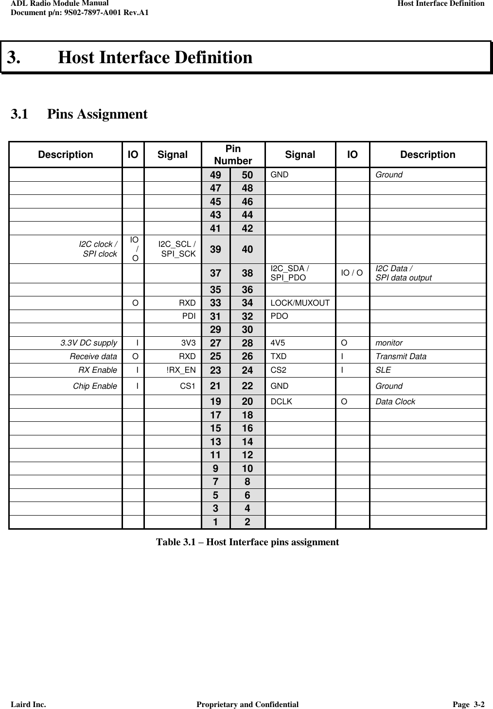
![ADL Radio Module Manual LAIRD Document p/n: 9S02-7897-A001 Rev.A1 Laird Inc. Proprietary and Confidential Page ii Revision History Date Revision Description Signature / Date 2010-10-06 EM1 Initial draft Prepared Pierre Montreuil Verified Approved 2010-10-06 EM2 General revision. Removed LQI measurement Updated the configuration section (section 5) Prepared Pierre Montreuil Verified Approved 2012-01-30 A Fig 4.8 and 4.9 - Remove remaining references to LQI from drawings. Table 4.2 – Rename ESC_END for ESC_SOF [LaB] Added demodulated analog output on pin 48 and GND on pin 50 Prepared Pierre Montreuil Verified Approved 2017-07 A1 Final Prepared H. Lin Verified Approved](https://usermanual.wiki/Cattron-North-America/78970/User-Guide-3568751-Page-2.png)
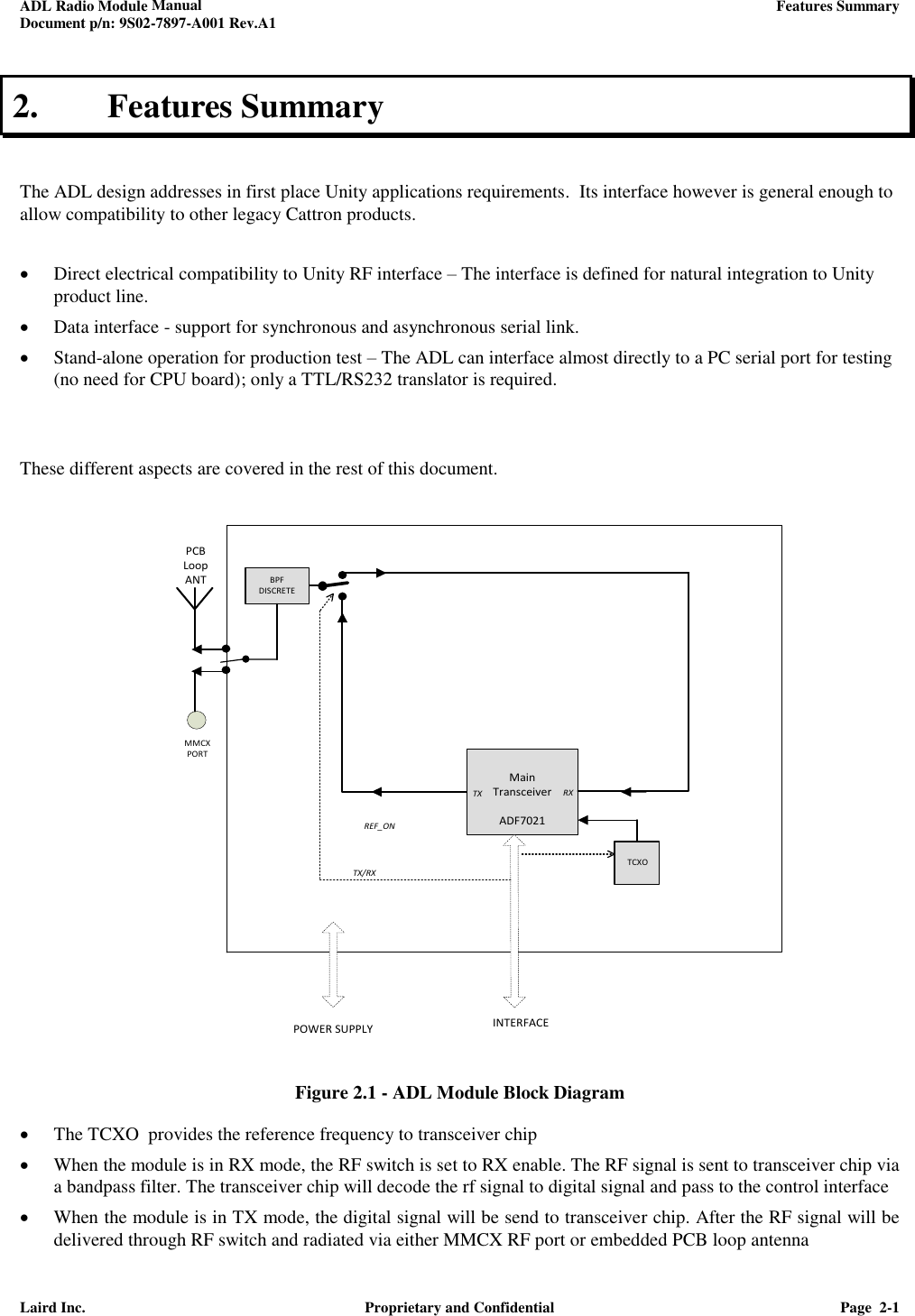
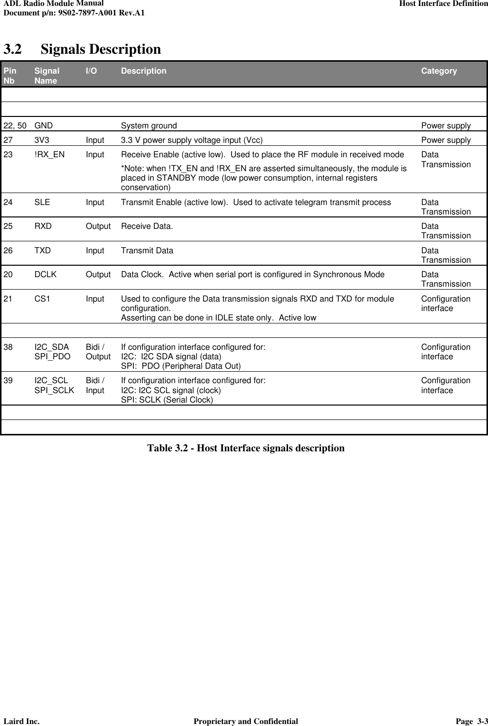
![ADL Radio Module Manual ADL Configuration Concept Document p/n: 9S02-7897-A001 Rev.A1 Laird Inc. Proprietary and Confidential Page 4-4 4. ADL Configuration Concept All LRM configuration and status parameters are accessible through addressable registers. - All parameters can be read in any of the following state: IDLE, RX, TX - All writable parameters can be written in the following state: IDLE only In order to facilitate adaptation to different platforms, the ADL configuration registers can be accessed using anyone of three methods: I2C, SPI or serial asynchronous with ASCII strings. The definition of the configuration registers is given in reference [3]. This section addresses the basic description of all these three methods. 4.1 Stand-Alone Test Mode The LRM can be operated in stand-alone mode for production/service tests. In this case, only a 3.3VDC supply is needed, and a RS232/TTL transceiver (like Cattron FLASHBOX) to connect to a PC serial port. 21ADL, host interface26RXDTXD25!CONFIG3V3GND2722RS232 - TTL transceiver(ex:Test Jig)3.3VDCRS232PC, running automated test program, or ANSI terminal emulation software*Note: The LRM !RX_EN, !TX_EN and !RESET all have internal pull-ups, so they can be left unconnected. Figure 4.1 - ADL connection for stand-alone operation The LRM will support several built-in test modes to ease testing from a PC. For example a. Transmission Tests - Generation of different type of carrier: unmodulated (CW), or modulated with “101010..” or pseudo-random sequence - Automatic generation of test RF frames with predefined content b. Reception Tests - Measure PER (packet error rate) when receiving the predefined test RF frames - Measure RF input level More details about the test modes can be found in reference [9P13-7949-A001].](https://usermanual.wiki/Cattron-North-America/78970/User-Guide-3568751-Page-11.png)