Cattron North America 844TX Remote Crane Control User Manual 142108d CMMDPRO
Laird Controls North America Inc. Remote Crane Control 142108d CMMDPRO
UserManual.wiki
>
Cattron North America
>
844TX User Manual
Users Manual
Navigation menu
Upload a User Manual
Namespaces
Wiki Guide
HTML
PDF
Info
Views
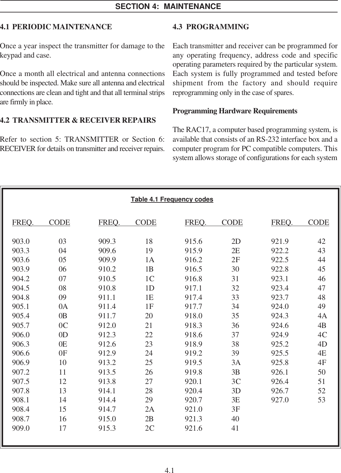
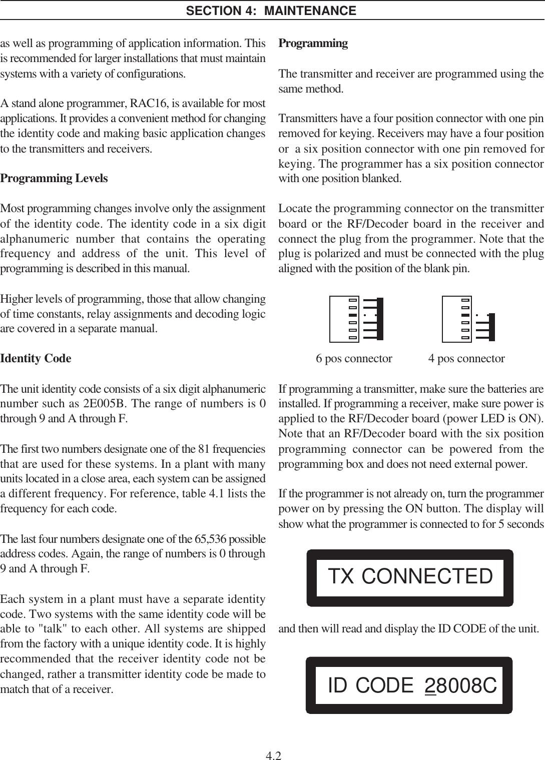
User Manual
Discussion / Help
Navigation