Celletra C-BPB PCS Multi-Channel Amplifier Antenna User Manual SBnnnn Hardware and Setup Guide
Celletra Ltd. PCS Multi-Channel Amplifier Antenna SBnnnn Hardware and Setup Guide
Celletra >
Contents
- 1. Users Manual
- 2. RT for Revised Manual
Users Manual
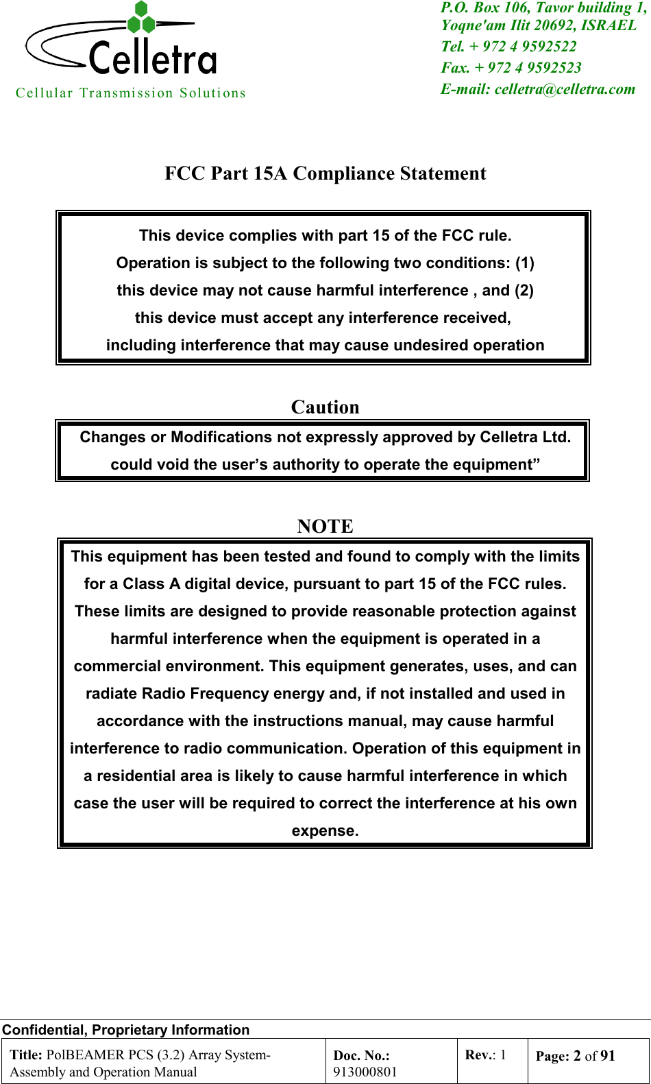
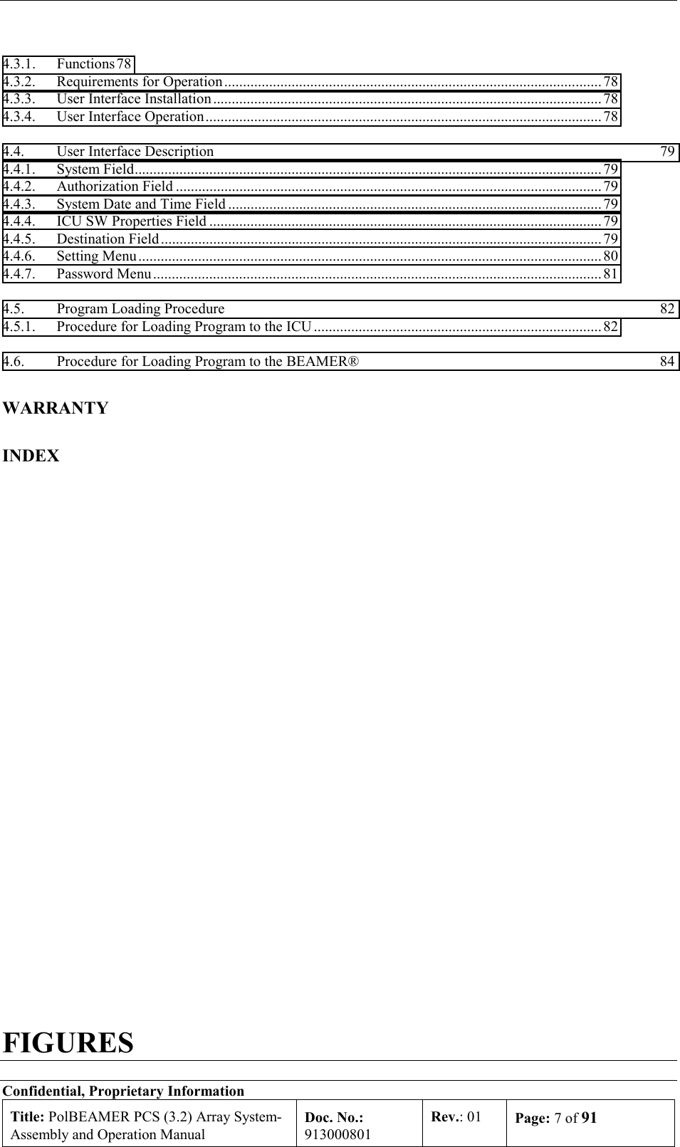
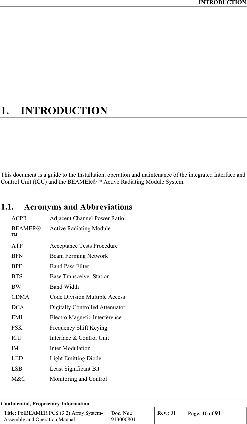
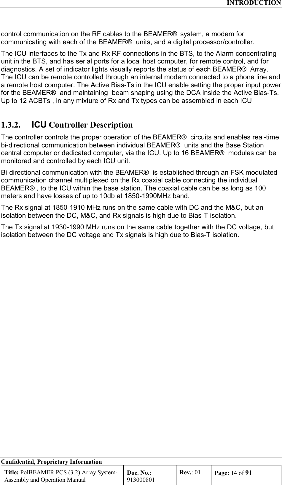
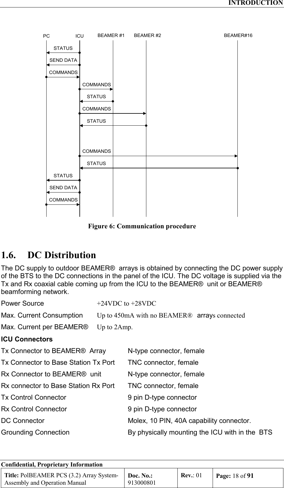
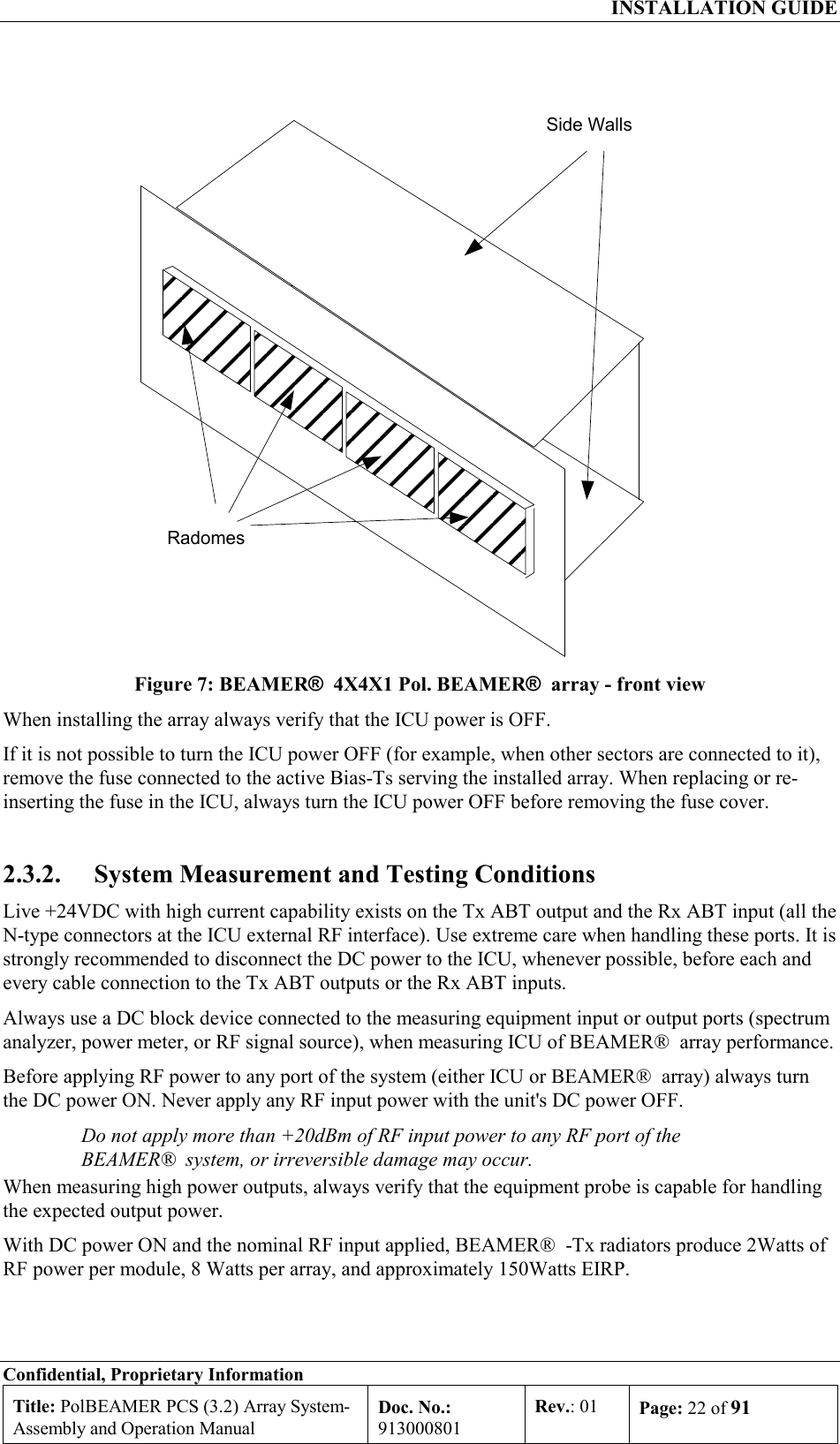
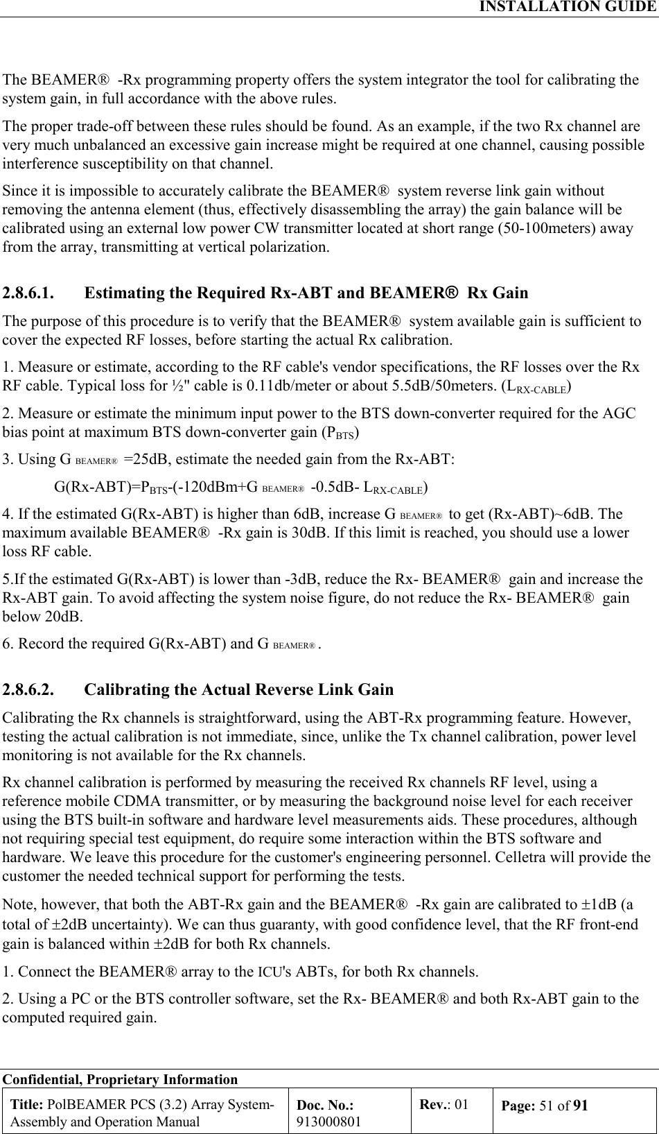
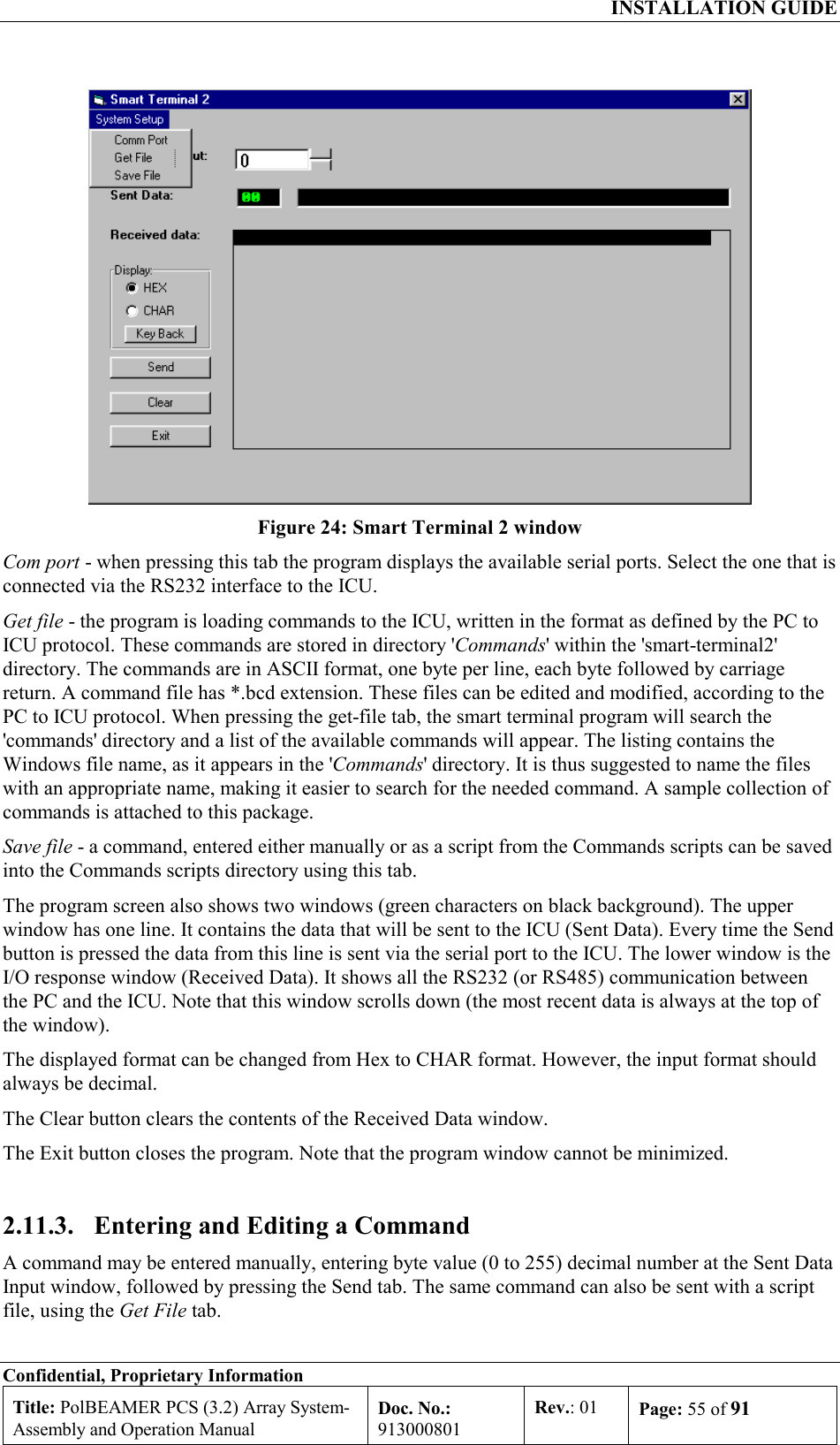
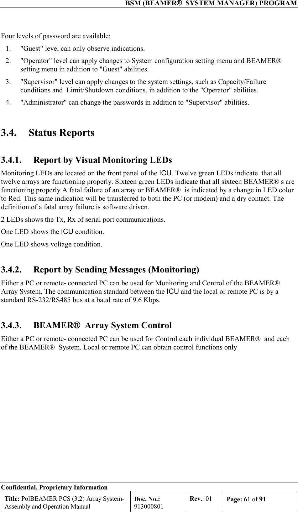
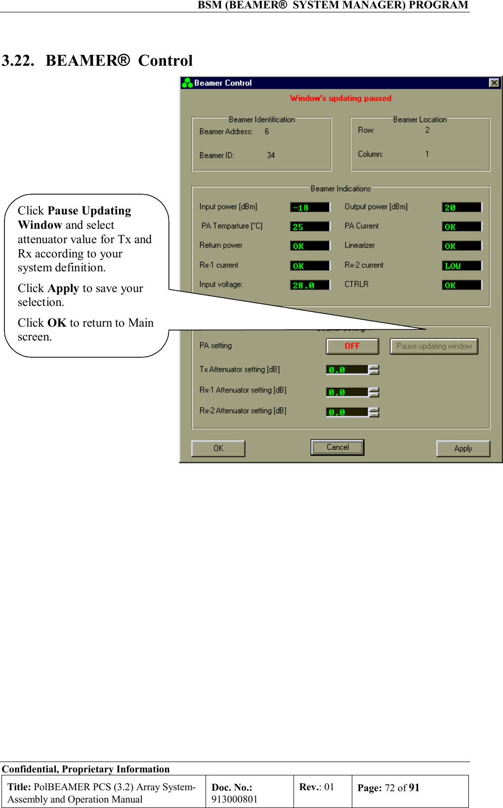
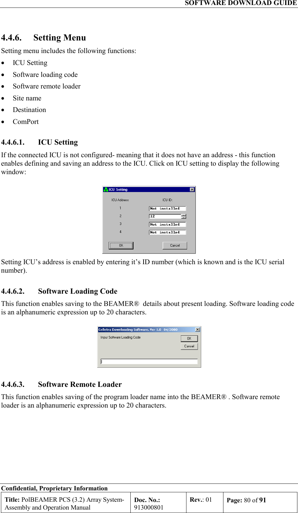
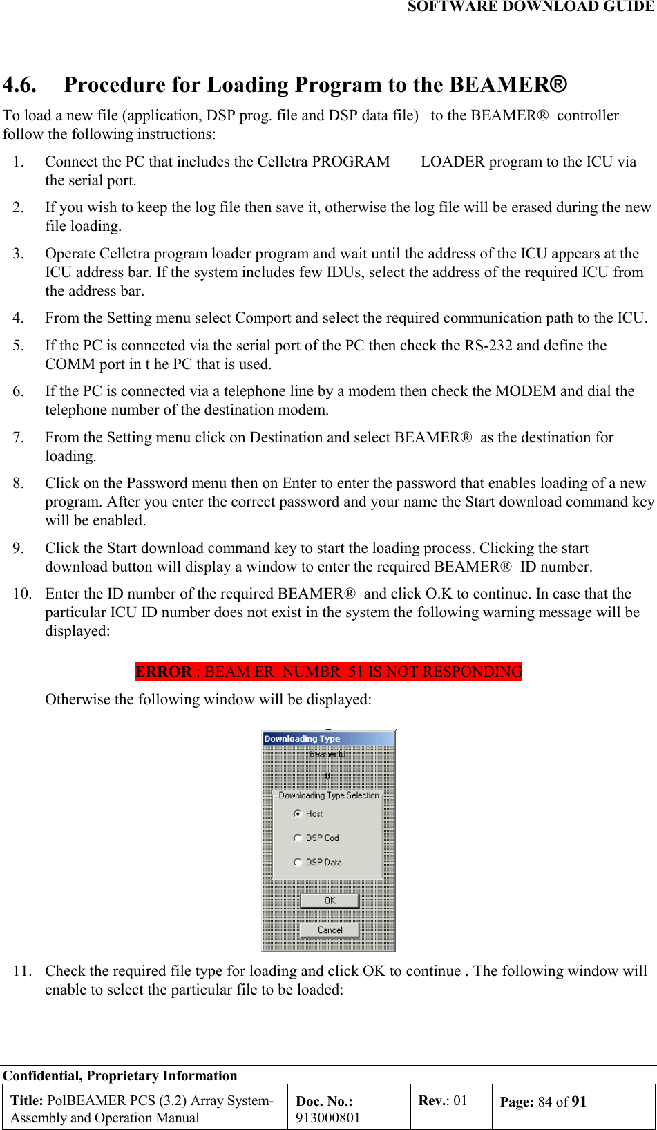
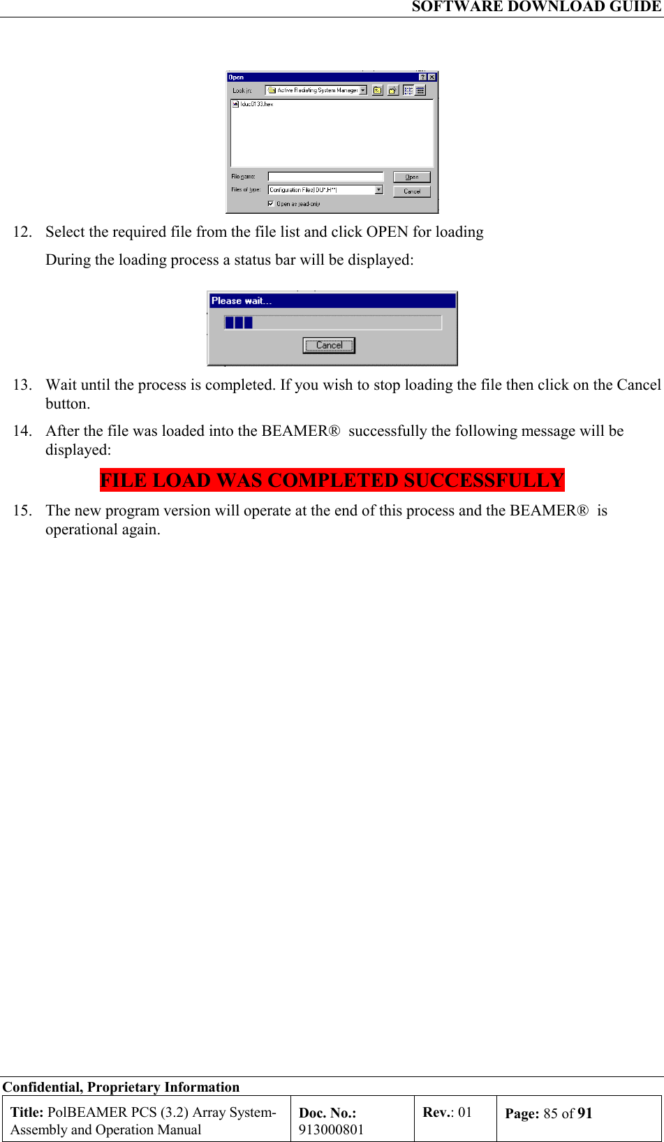
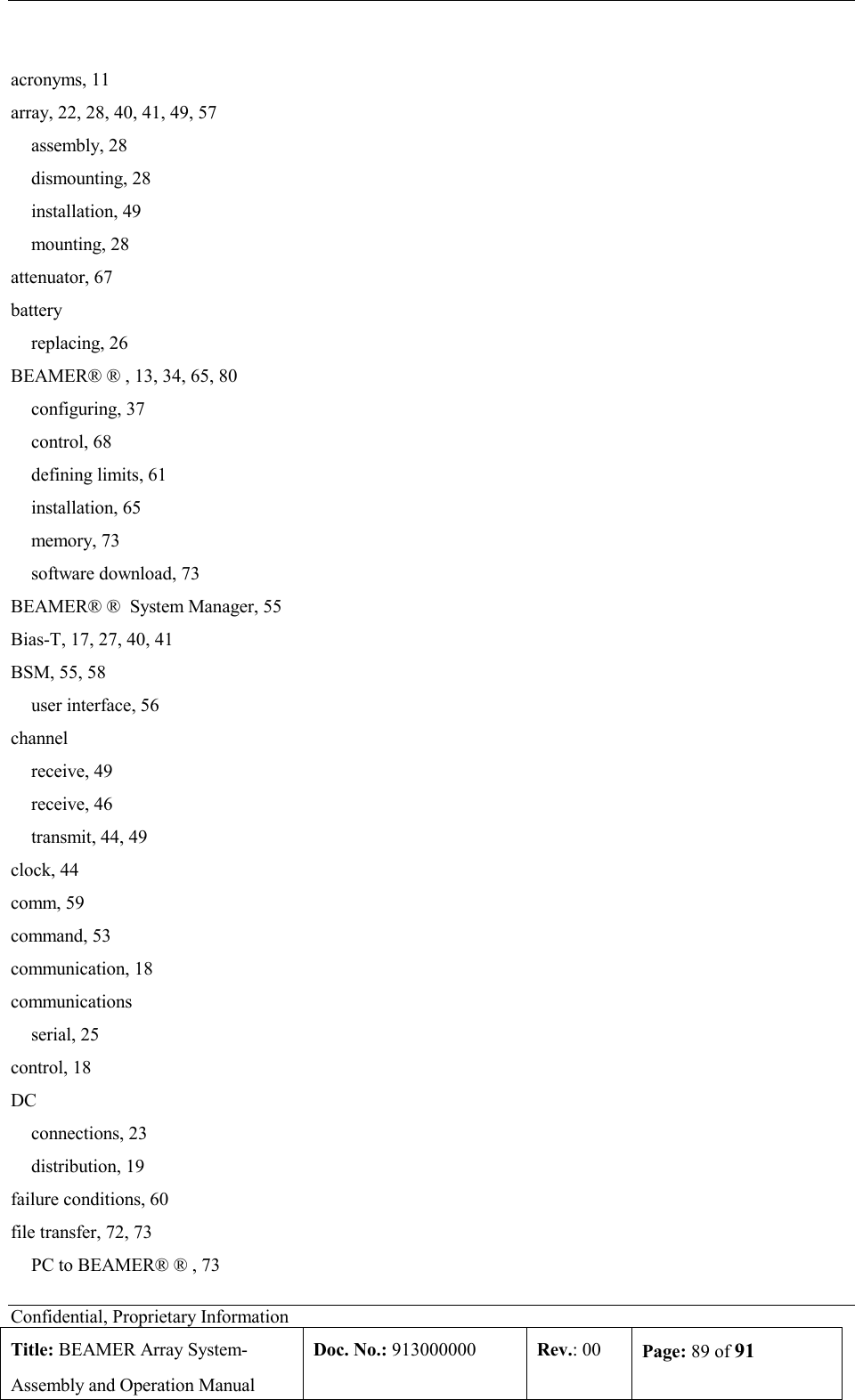
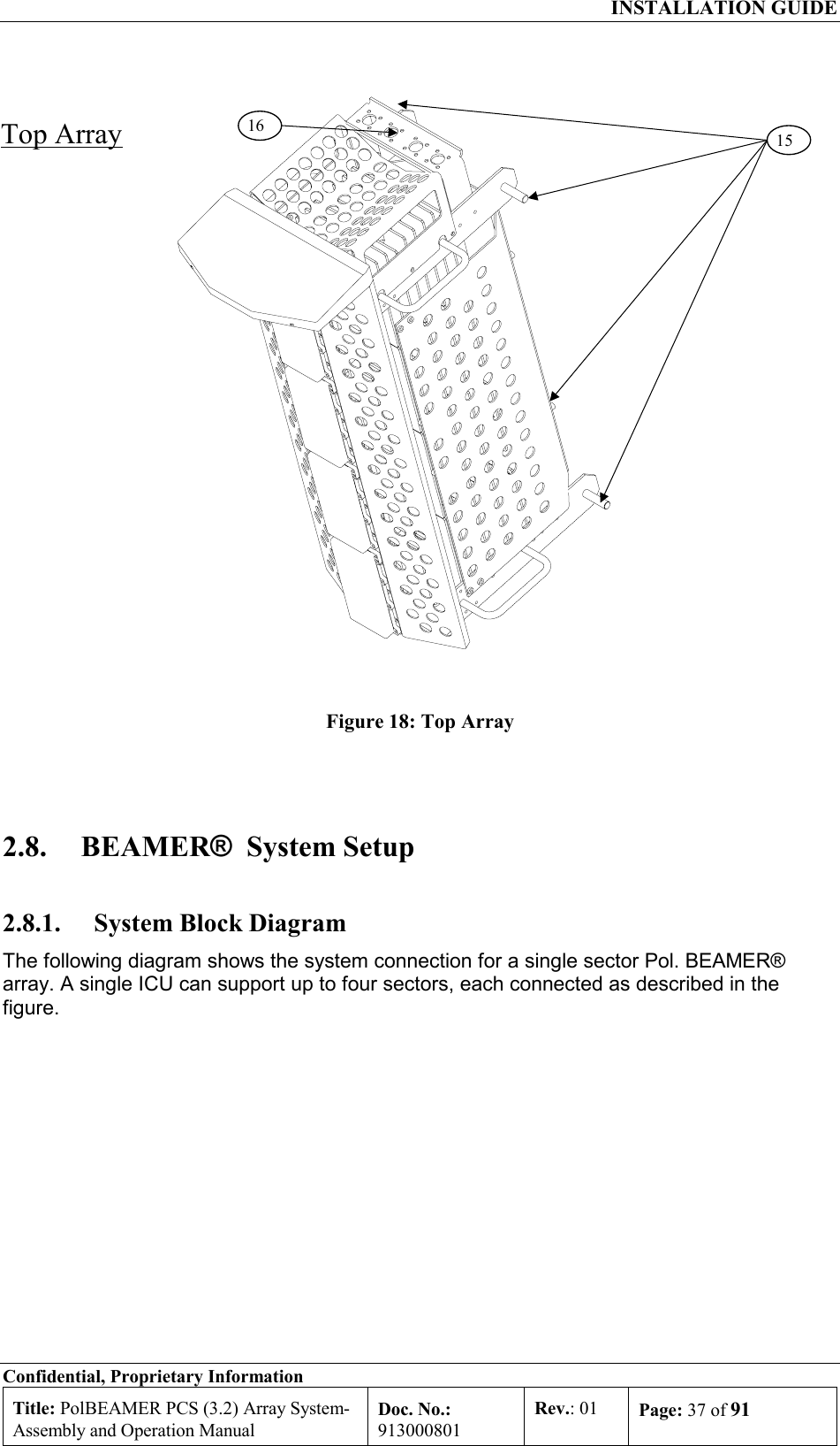
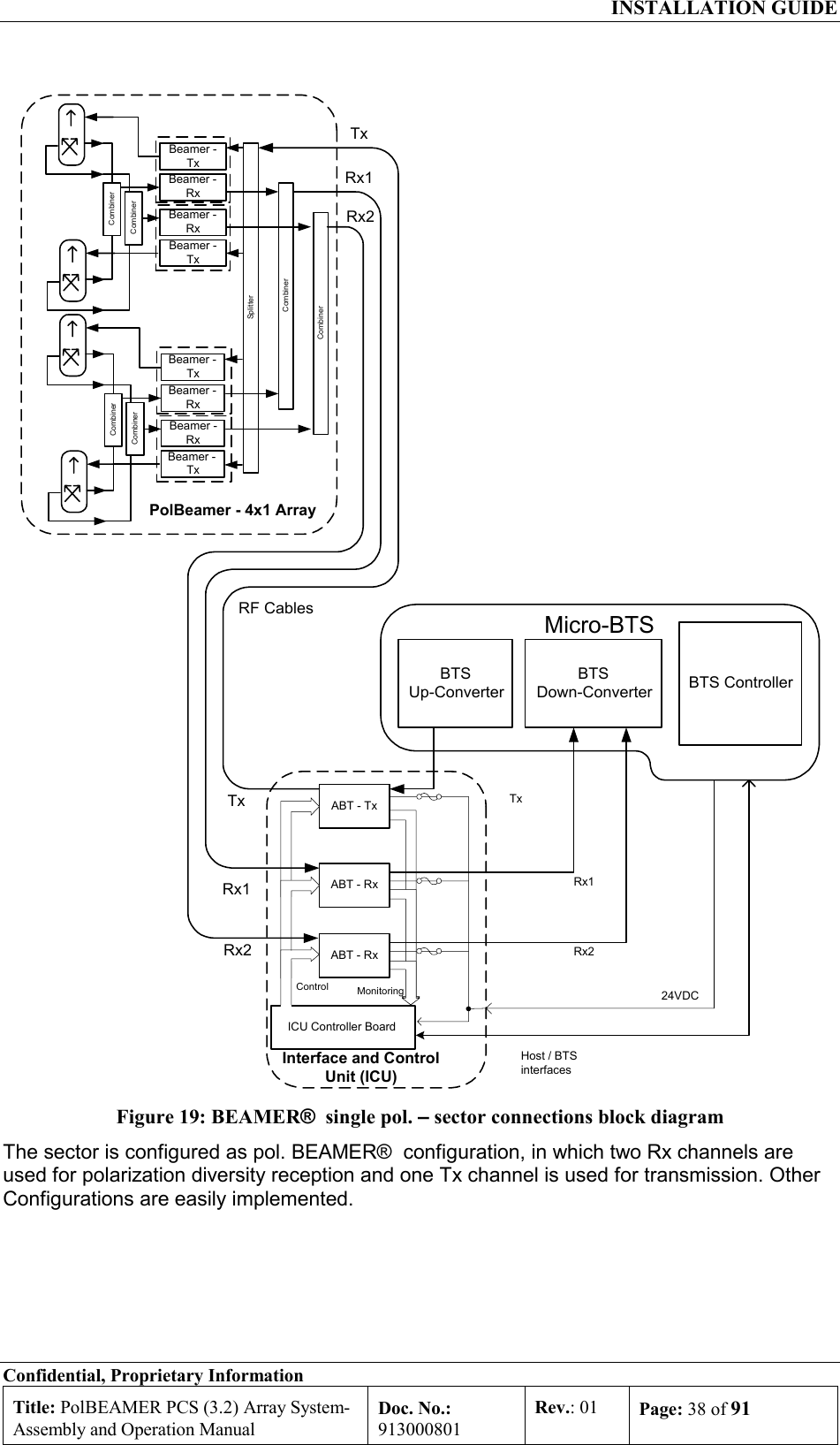
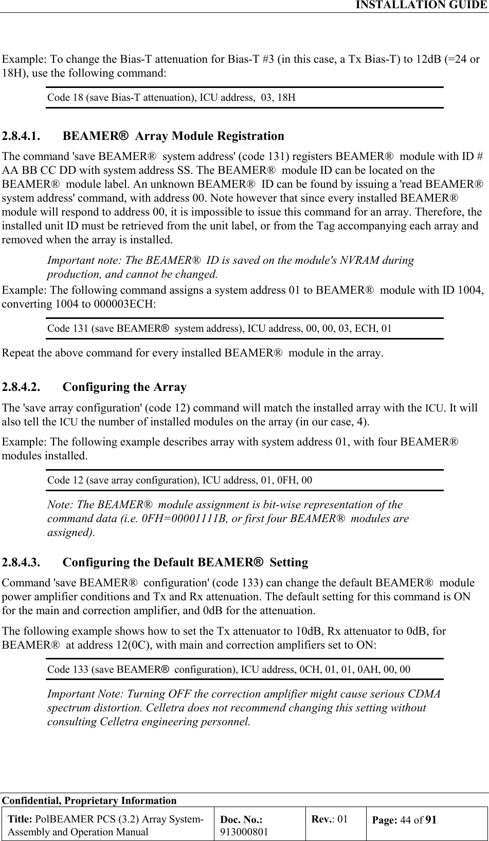
![INSTALLATION GUIDE Confidential, Proprietary Information Title: PolBEAMER PCS (3.2) Array System- Assembly and Operation Manual Doc. No.: 913000801 Rev.: 01 Page: 27 of 91 2.4.4. Bias-Ts In this manual, Bias-Ts are also termed 'sub-array', since each Bias-T can serves an independent portion of an array (i.e., Tx sub-array or Rx1 and Rx2 sub-arrays, which are all physically part of the same array, but are logically independent entities). The Bias-Ts serve four purposes: 1. Supply DC voltage to the BEAMER® modules within the sub-array. 2. Provide DCA controlled RF amplification stage, to overcome possible RF distribution losses and to provide control on the transmitted or received output power per sub-array. 3. Connect the BEAMER® modules Telemetry to the ICU controller via the superimposed FSK link. 4. Enable the S/W downloading to each BEAMER® of the array using the Telemetry channel. The sub-array direction of the ICU Bias-T connector is N-type connector, capable of supporting the DC current to the sub-array. The BTS side is TNC type connector. The following figure shows the active Bias-T location on the ICU. Figure 11: Bias-T inputs / outputs and numbering Viewed from right to left, the Bias-Ts are organized as: [Rx1-Rx2-Tx], [Rx1-Rx2-Tx], [Rx1-Rx2-Tx], [Rx1-Rx2-Tx] Bias-T number 1 is on the far right going to Bias-T number 12 at the near left. These (physical) numbers also serve as logical addresses for the Bias-T (sub-arrays) at the system setup. In case less arrays are integrated in the system, the number of Bias-Ts will be reduced.](https://usermanual.wiki/Celletra/C-BPB.Users-Manual/User-Guide-166707-Page-27.png)


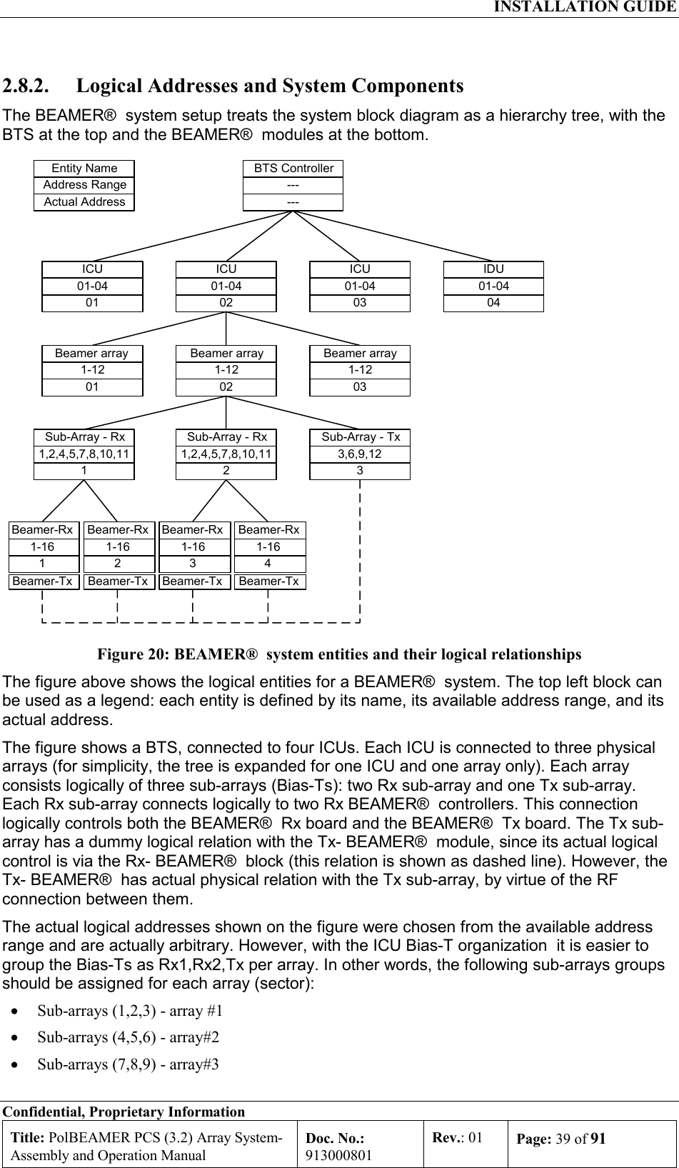
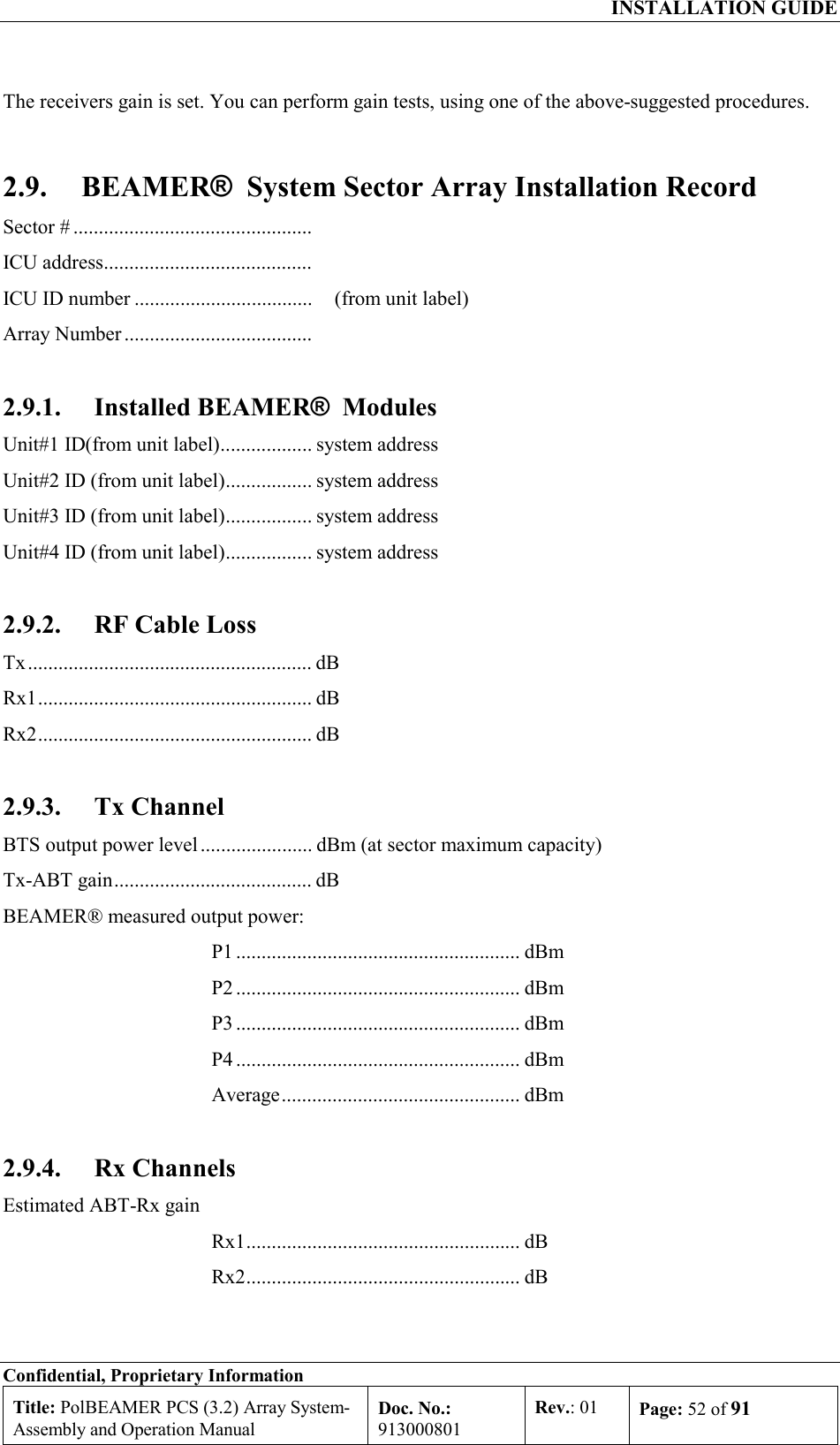
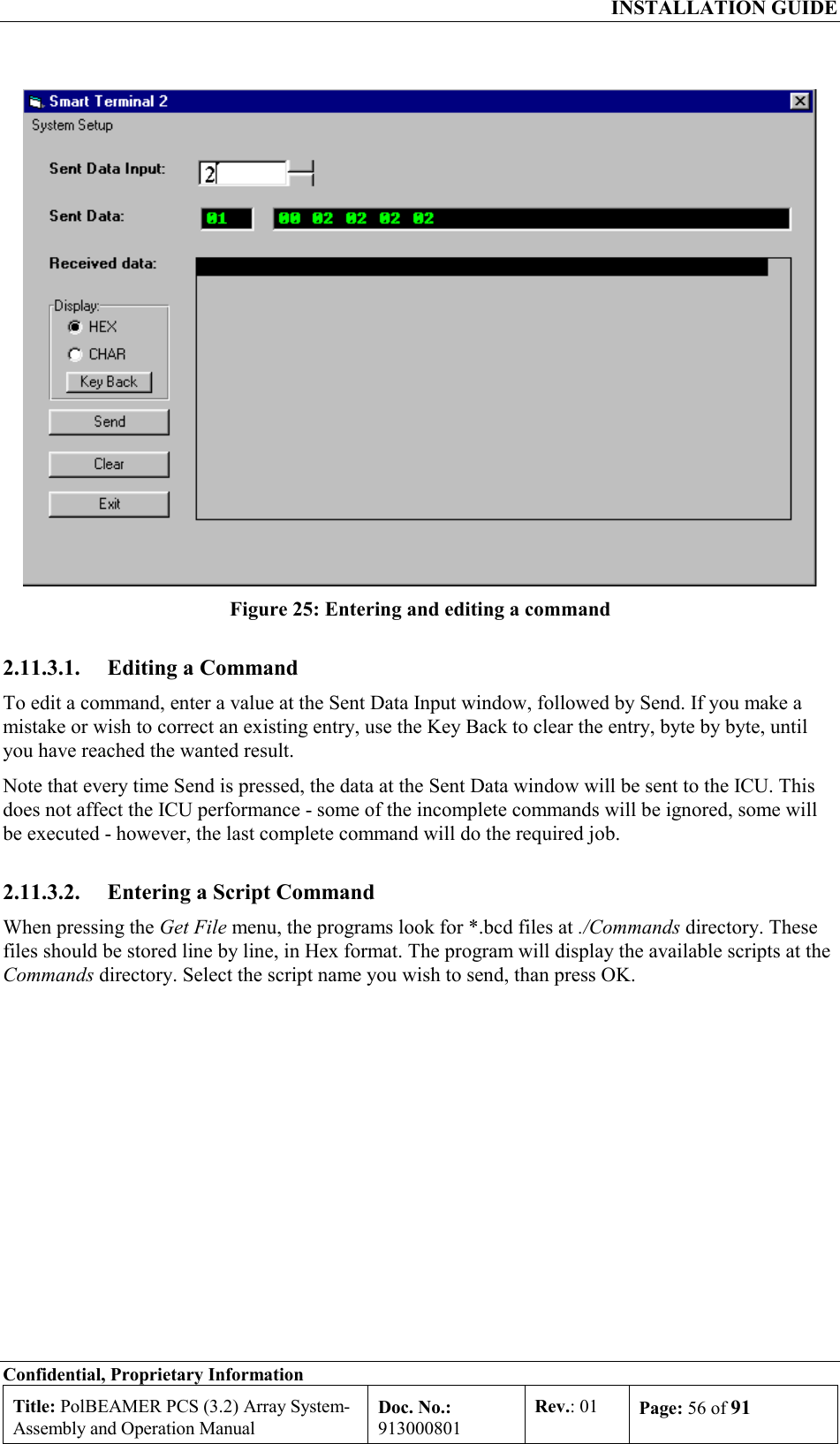
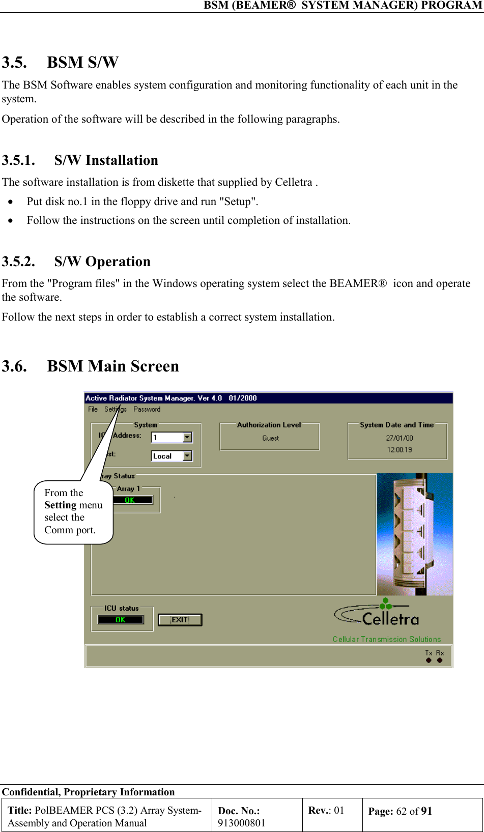
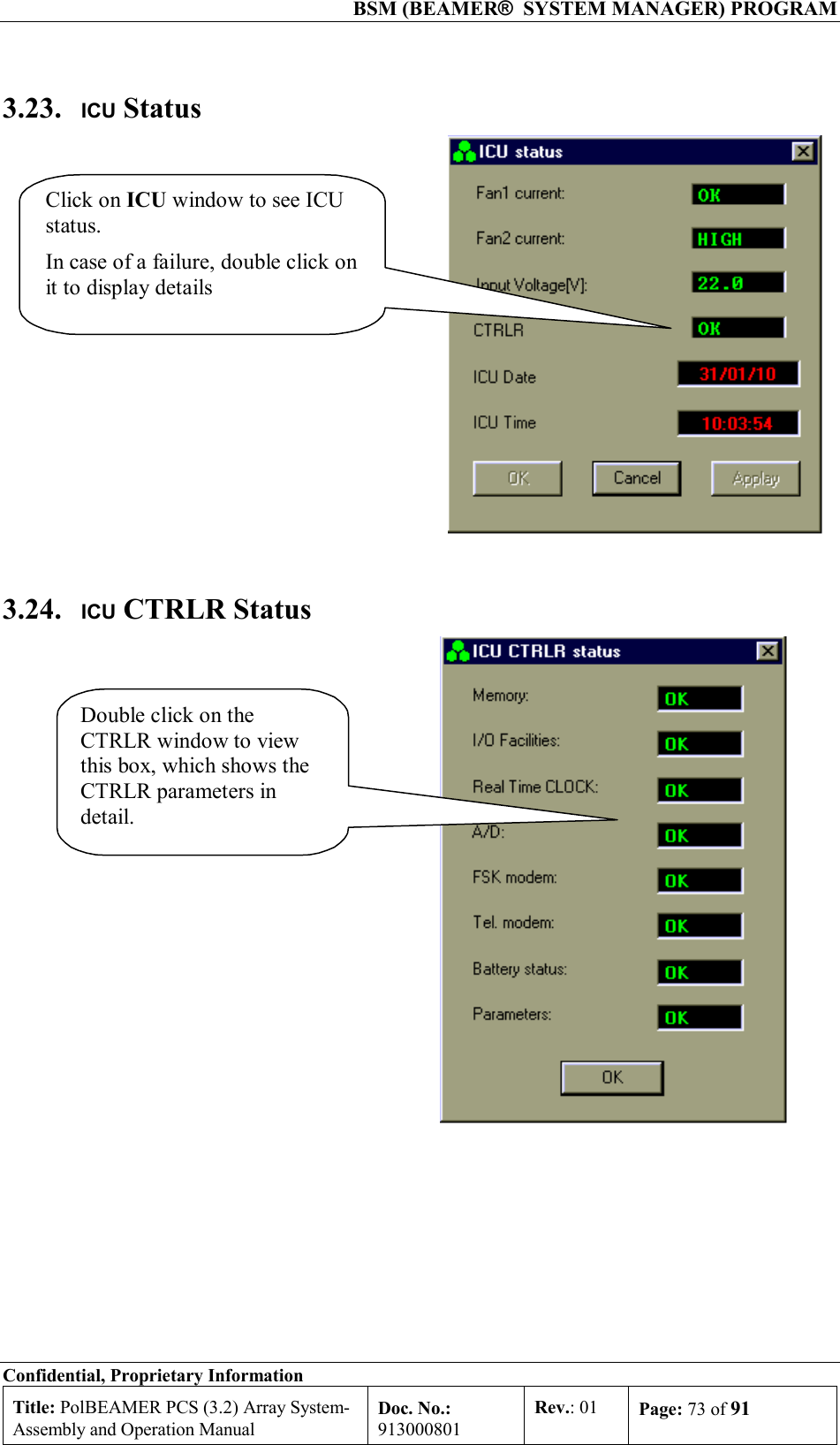
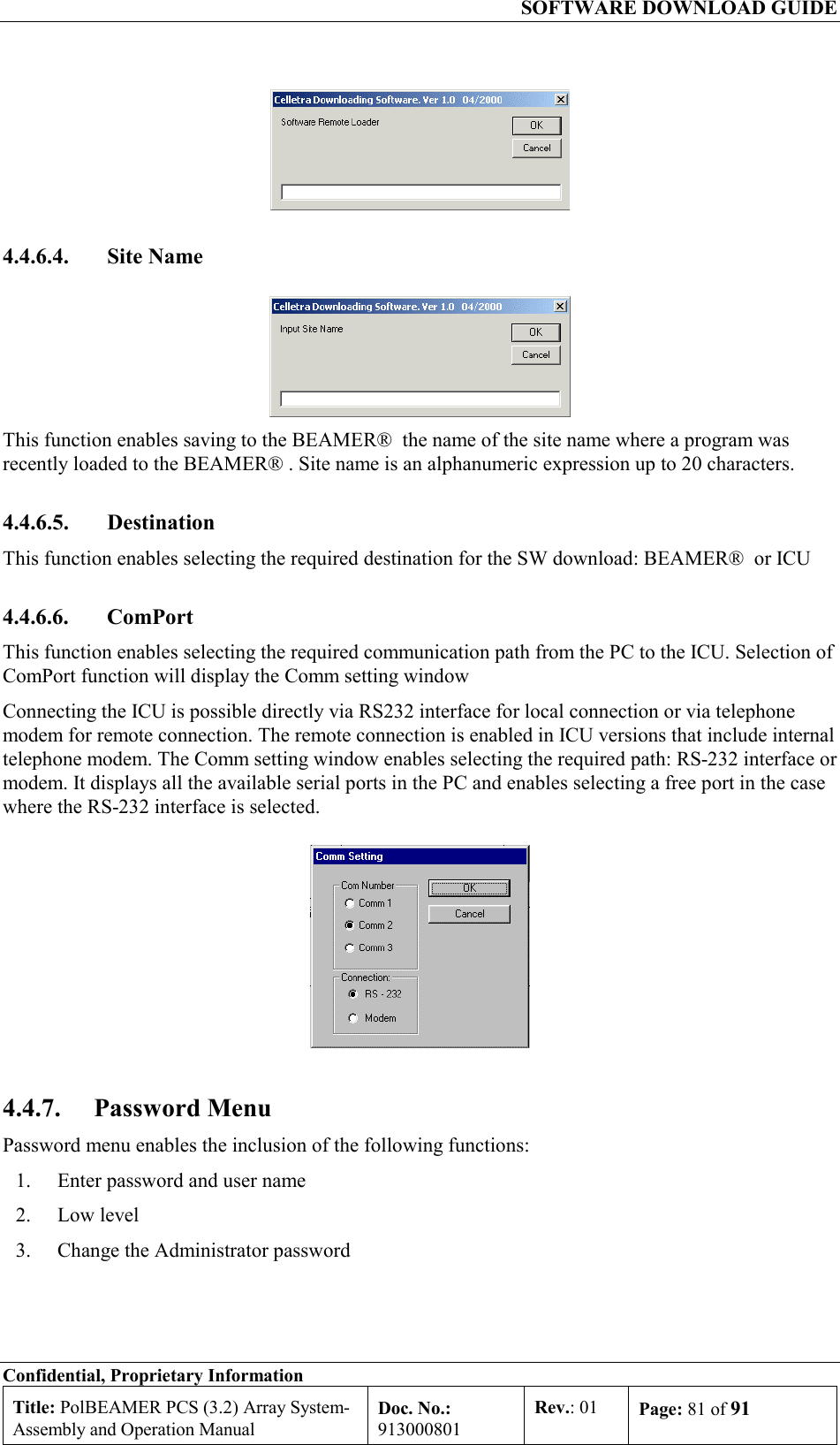
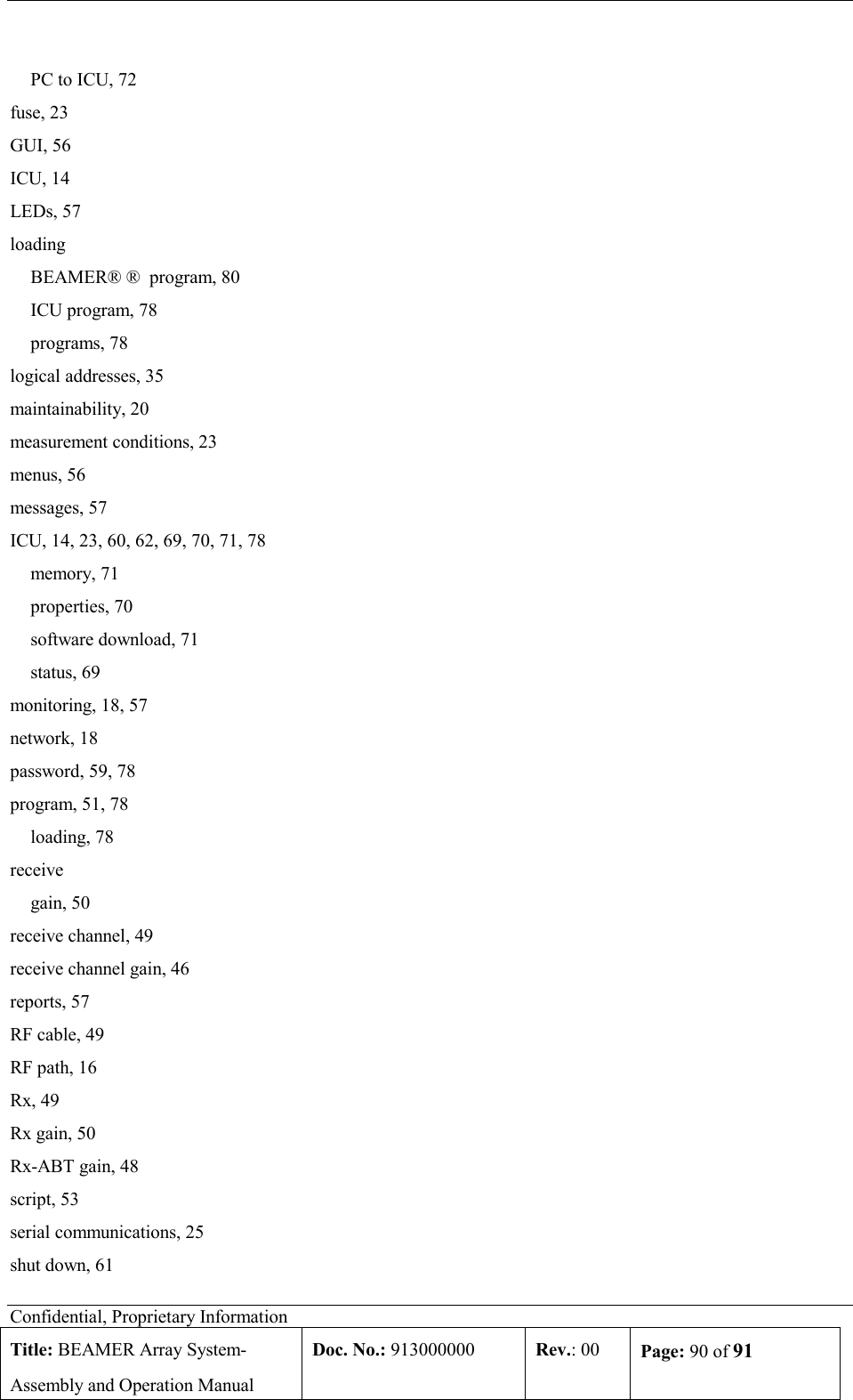
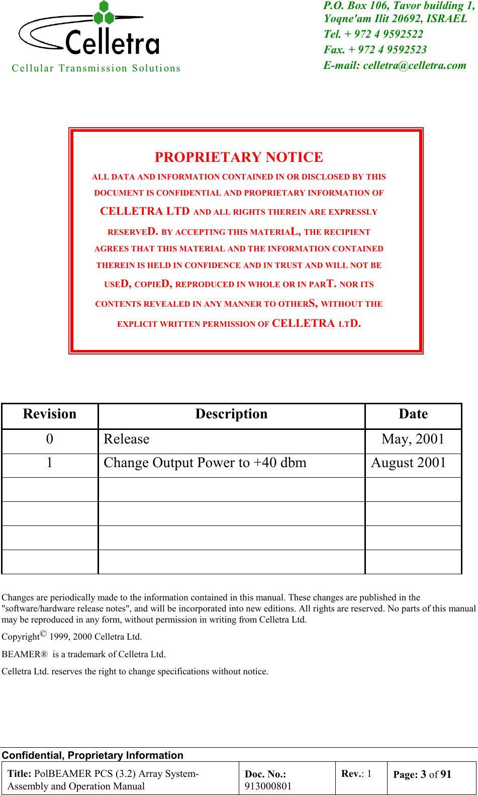
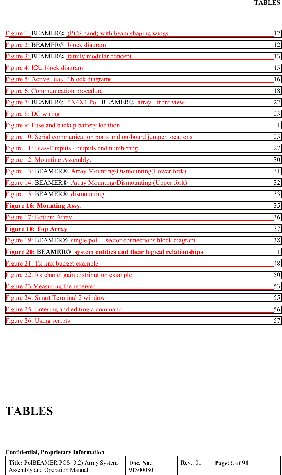
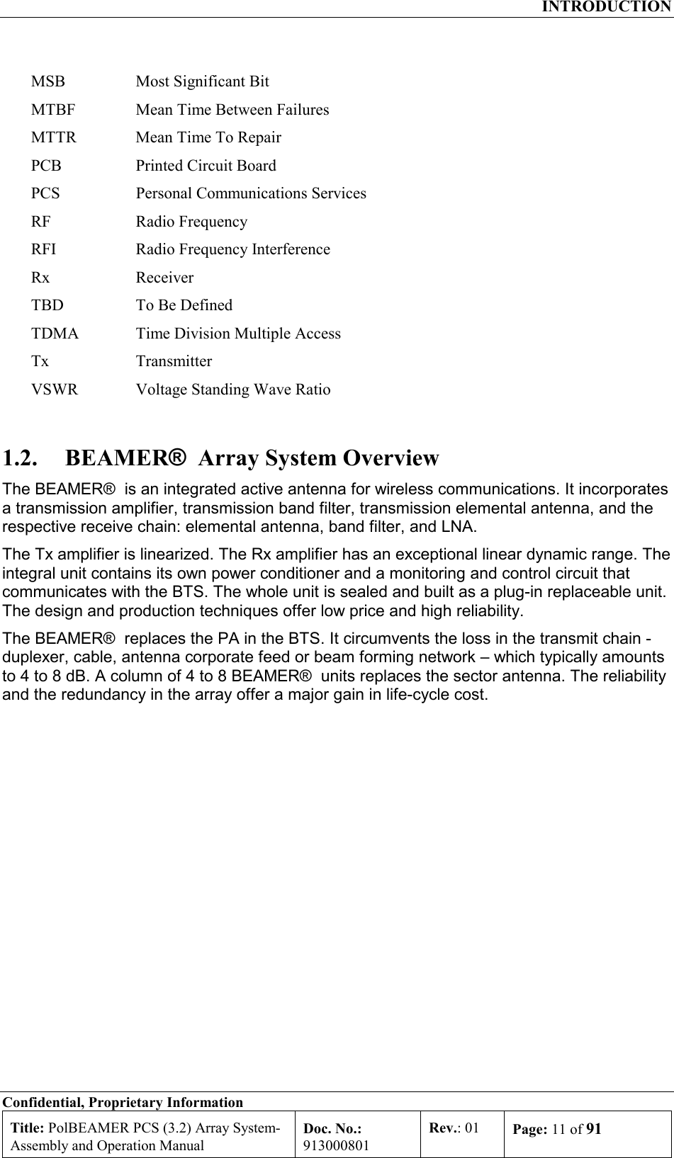
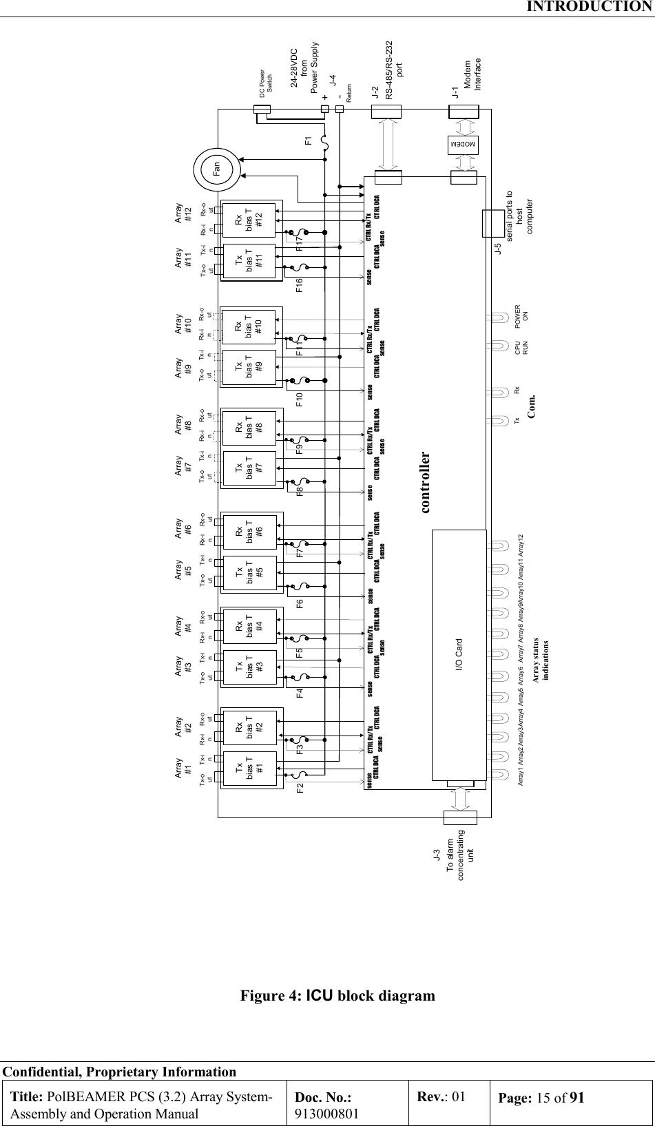
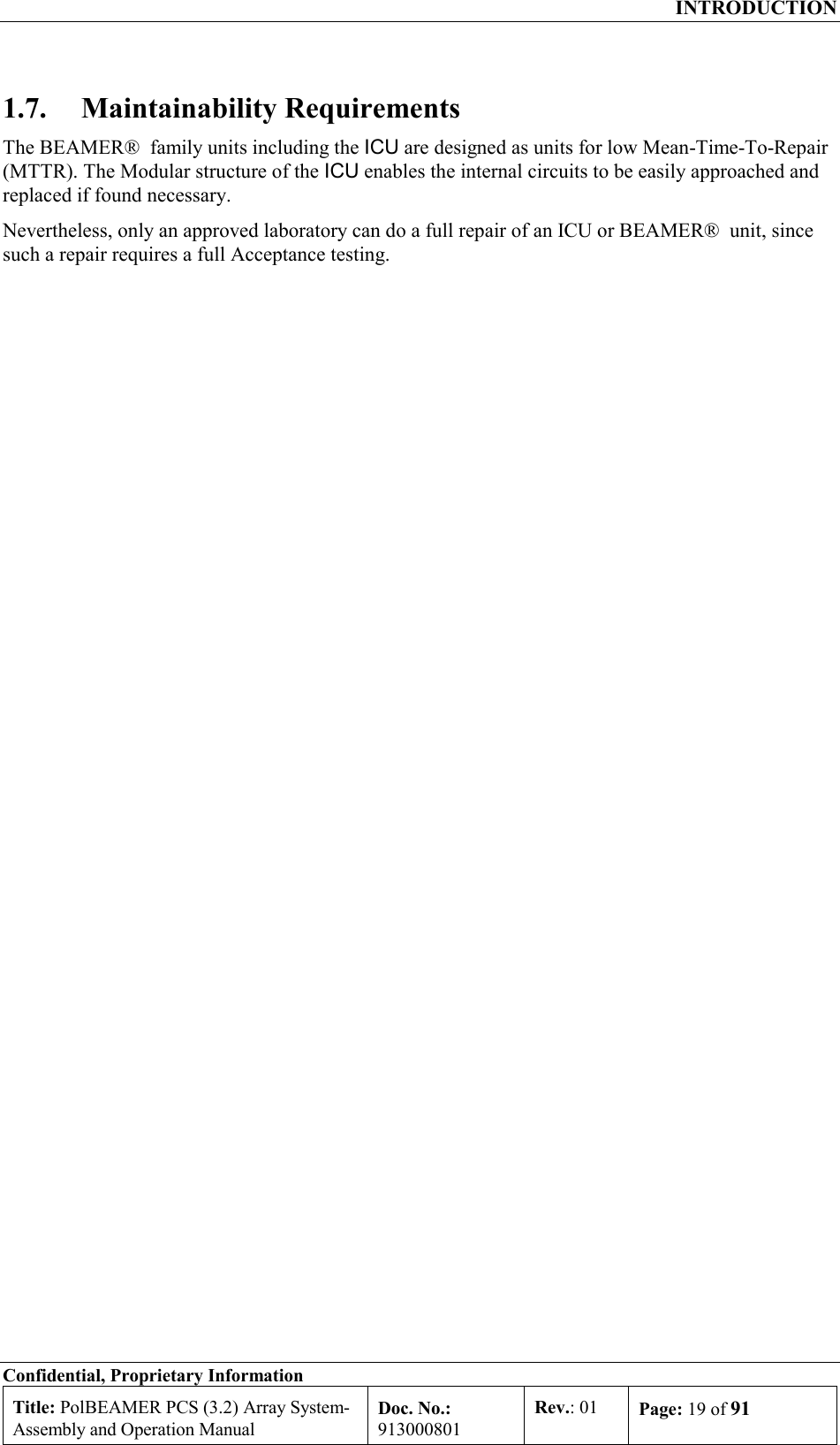
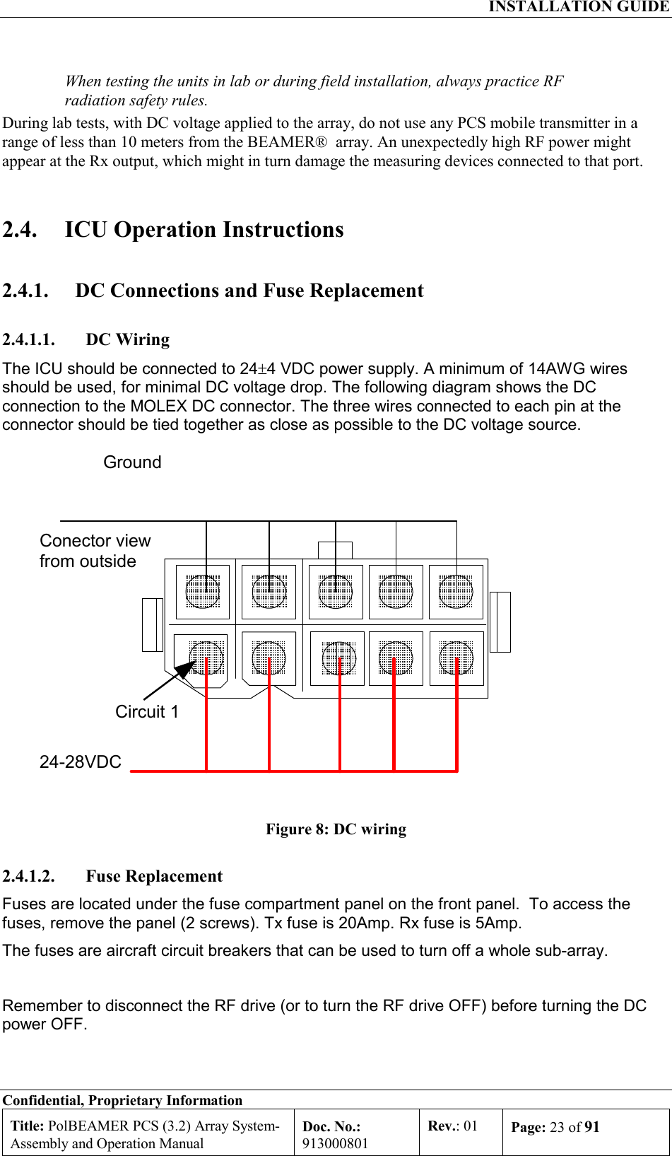
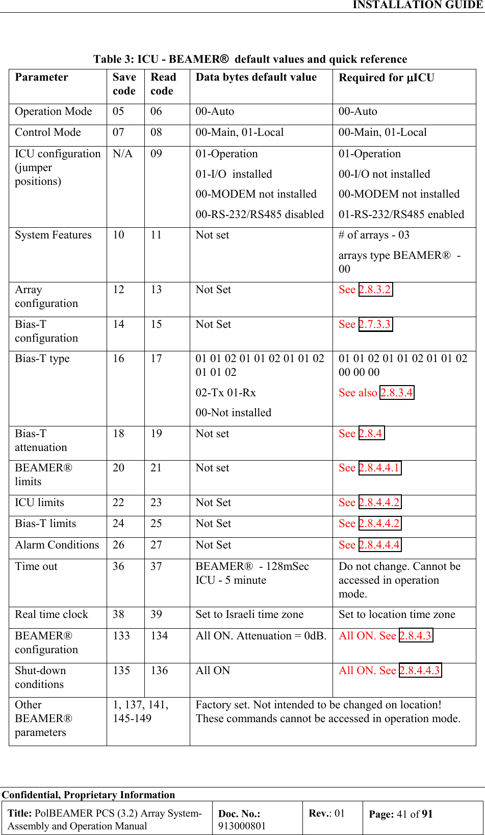
![INSTALLATION GUIDE Confidential, Proprietary Information Title: PolBEAMER PCS (3.2) Array System- Assembly and Operation Manual Doc. No.: 913000801 Rev.: 01 Page: 40 of 91 • Sub-arrays (10,11,12) - array#4 The following table summarizes the available address range for the system entities: Table 2: BEAMER® system logical addresses range Name Address range ICU 01 to 04. Address 00 reserved for testing Array 01 to 12(03). For Micro- ICU: maximum 03 (always pol. BEAMER® ) Sub-array (Bias-T) 01 to 12(09). For Micro- ICU: Same as physical address, maximum 09. BEAMER® 01 to 16. Address 00 reserved for testing 2.8.3. System Configuration and Setting Some of the ICU setup are already configured for the needed system configuration. This setup is saved on the ICU's Flash memory. Using the PC to ICU protocol commands, you can verify that the ICU is properly set. The following sections will guide you through the process of ICU setup verification. You can modify the setup to match your configuration at any time. Throughout this section, some command examples and data will be used. As a rule, all commands data and commands codes are given here in decimal representation, unless specifically specified, using 'H' prefix for hex numbering. Also, it is assumed that the reader has some knowledge with the PC to ICU protocol, given in [1]. The command sequence described in this section should be referred to as a system configuration guide, not as a PC to ICU programming manual. For more information, refer to the applicable documentation listed at the beginning of this chapter. Before setting up the system, avoid connect RF cables between the ICU and the BEAMER® array. Since the Tx and Rx gain are not calibrated yet, this is done to protect the BTS interface and the BEAMER® array from overdrive conditions. The following table can be used as a reference for the ICU and BEAMER® array setting. The table specifies the pre-set default values and points to the specific command code, used for reading or saving a parameter value. Note: Many values are not set. The following sections will instruct you how to set these values, tailored to the specific on-site installation. Caution: some values ( such as RS-232/RS-485 switch ,Time out and codes 1,137,141,145-149) are factory set and should not be changed on location. In part ICU are, these values relate to the BEAMER® array calibration and operation modes. Modification of these values, without coordination and specific authorization from Celletra engineering, can cause invalid array performance and should be avoided. The changes are possible by the highest password authorization only.](https://usermanual.wiki/Celletra/C-BPB.Users-Manual/User-Guide-166707-Page-40.png)
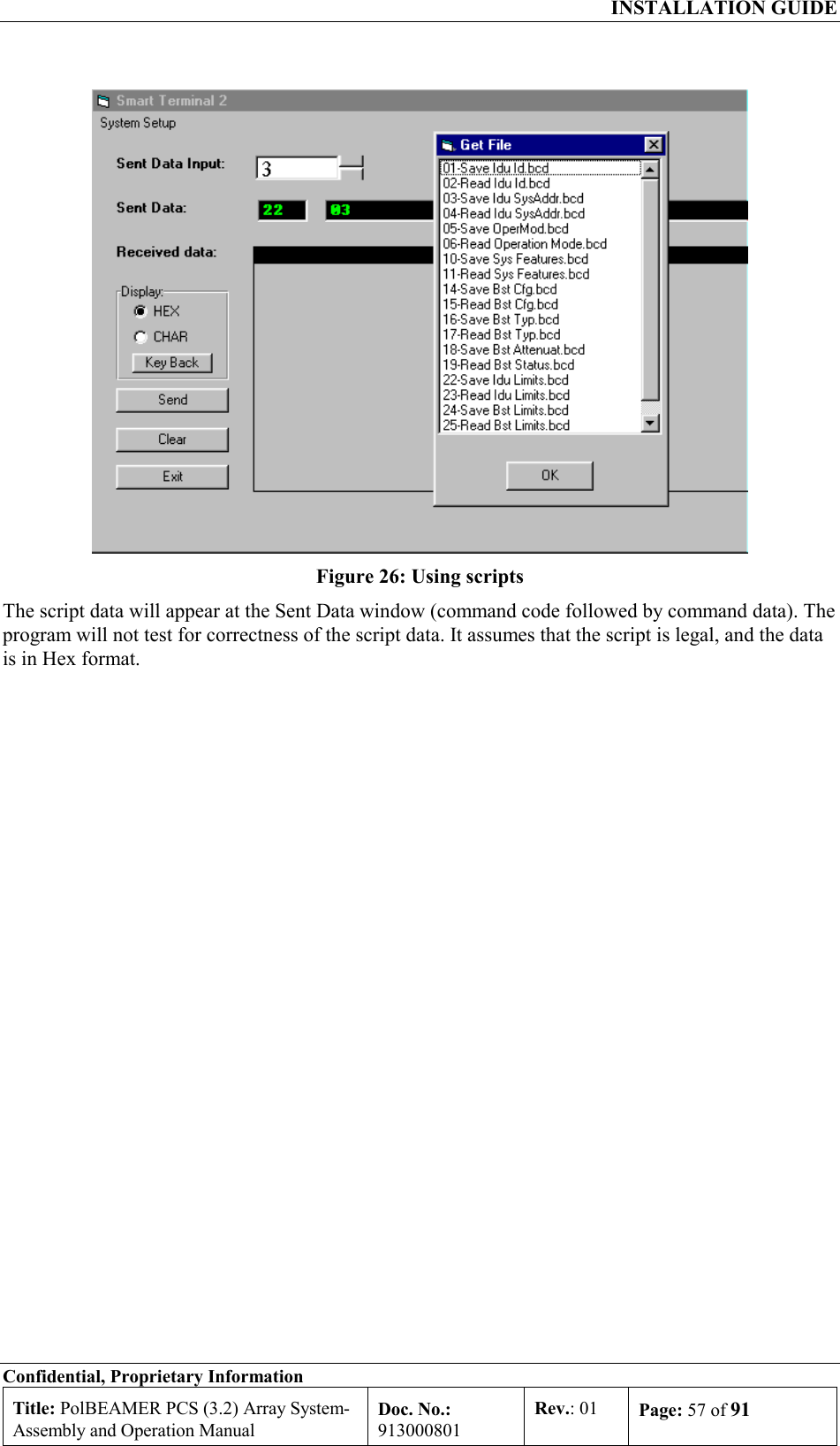
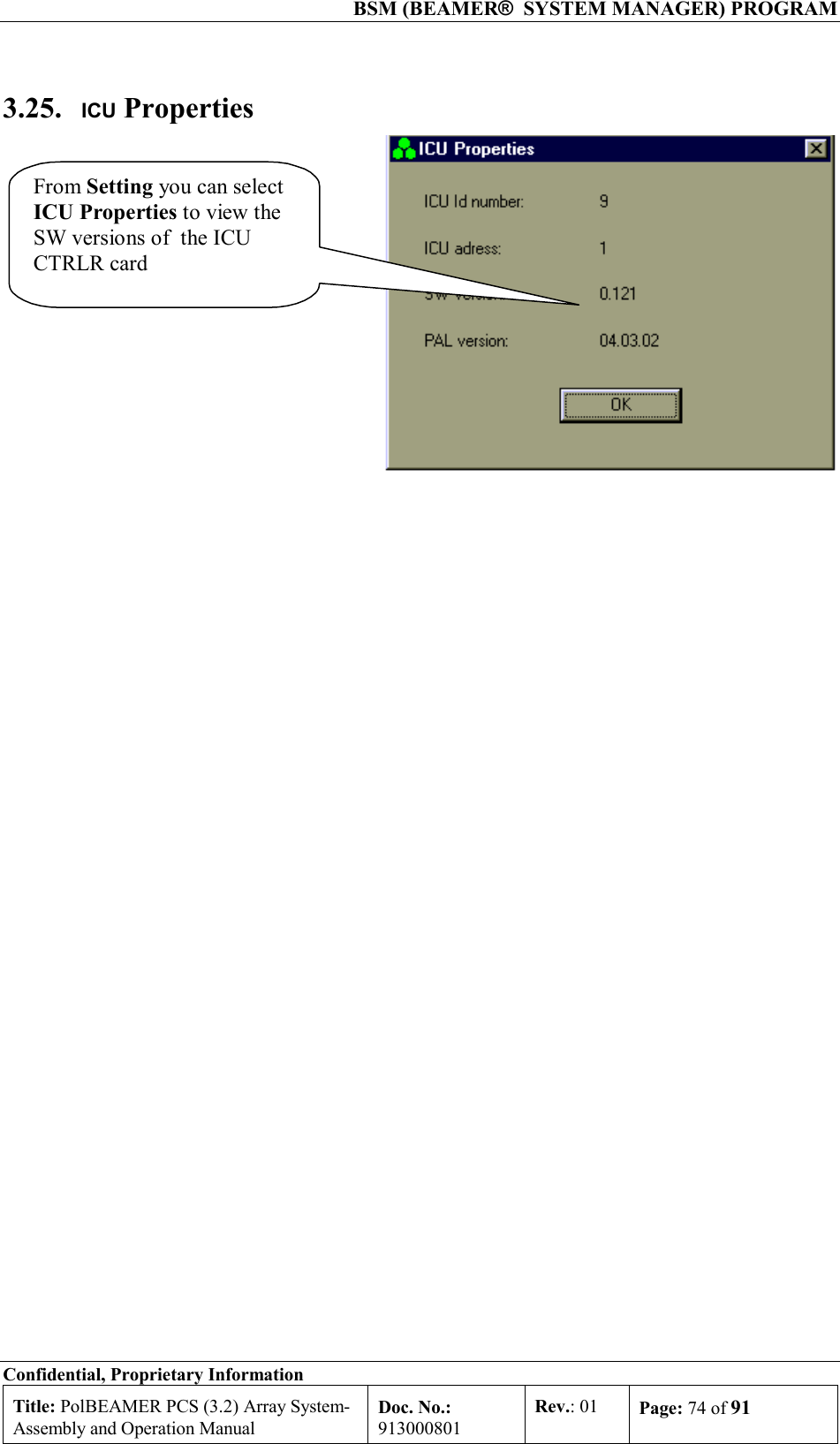
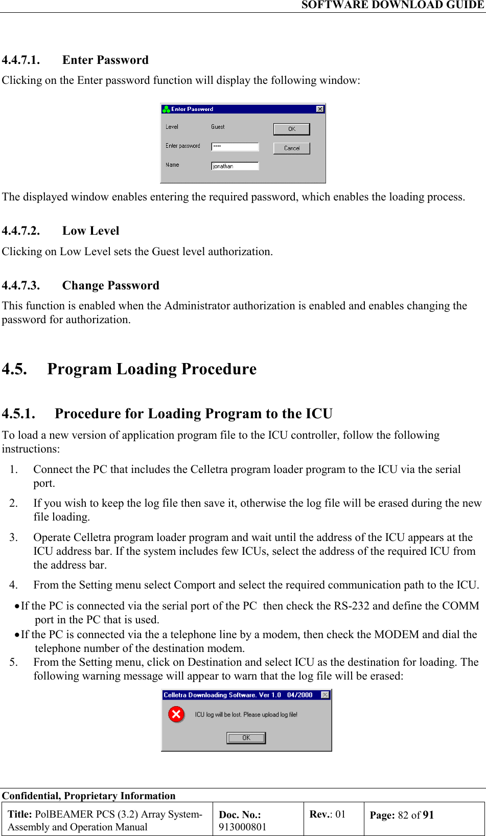
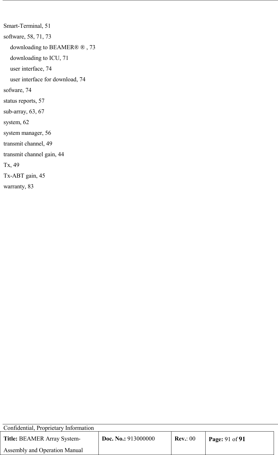
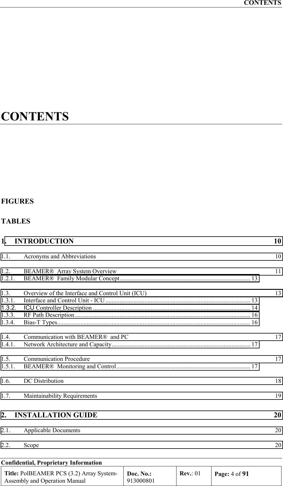
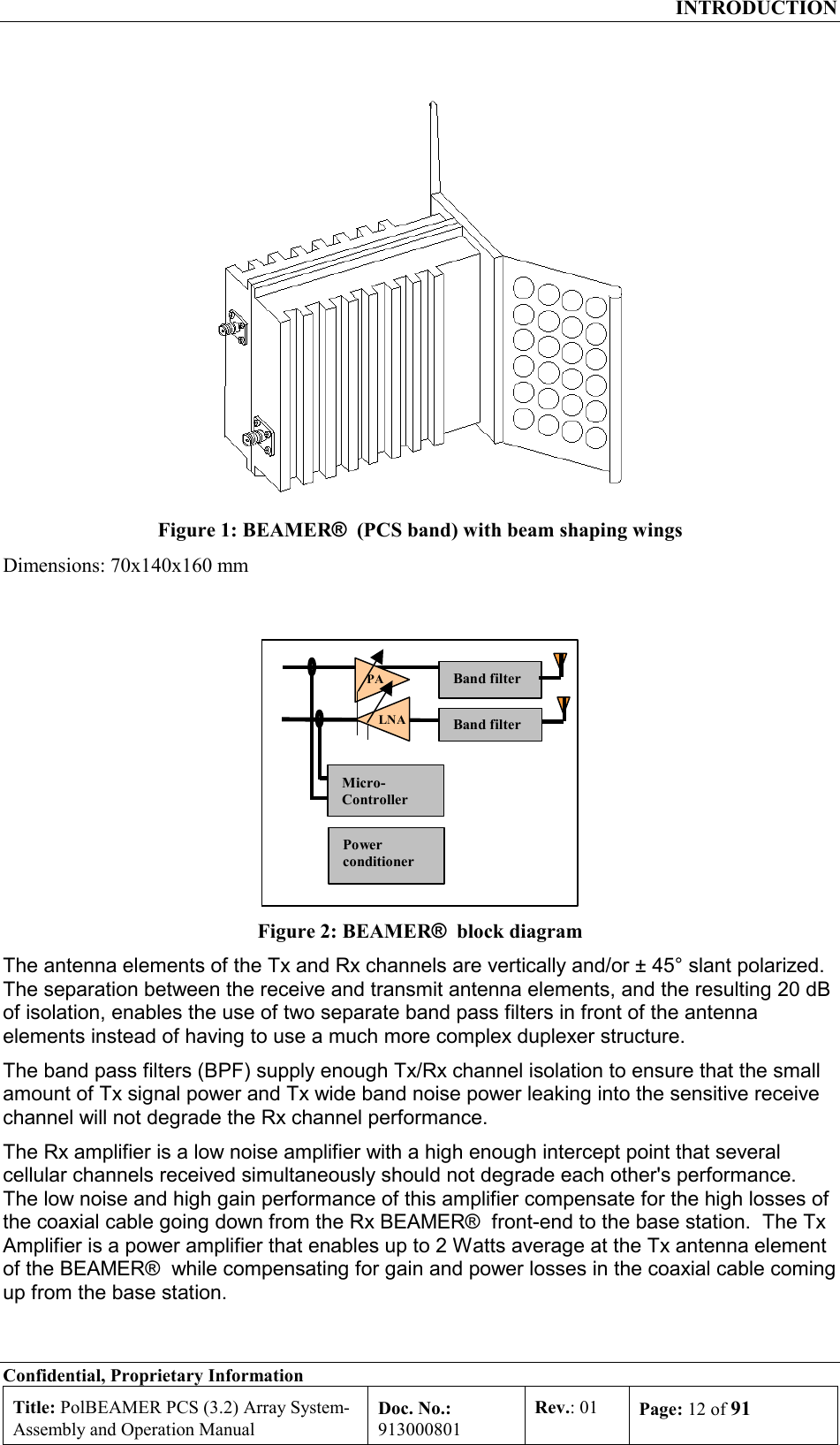
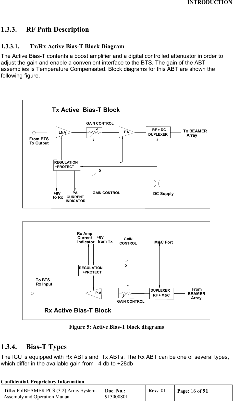
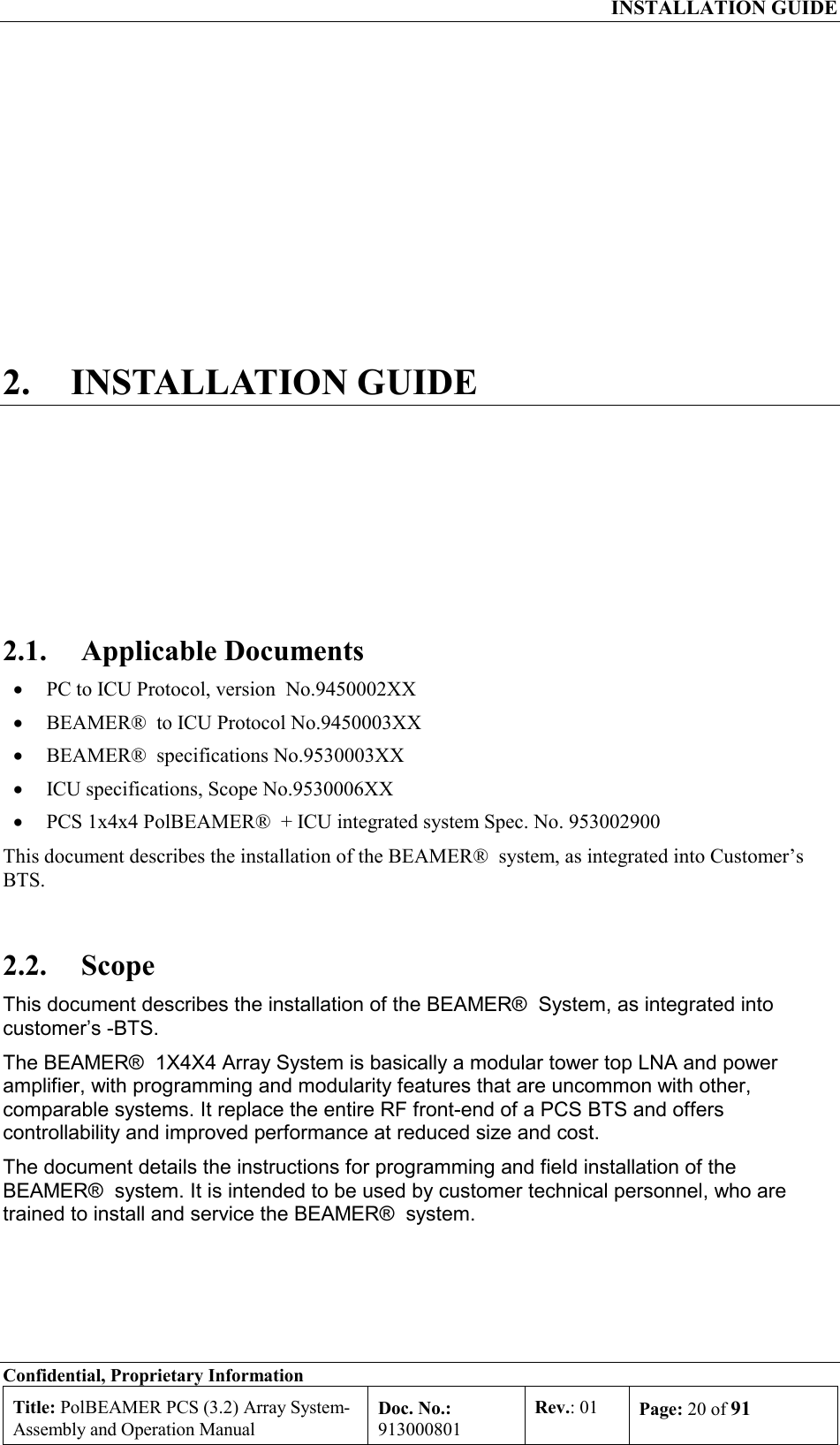
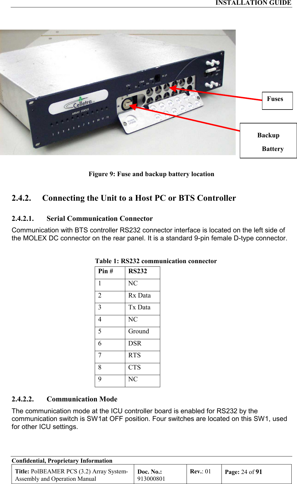
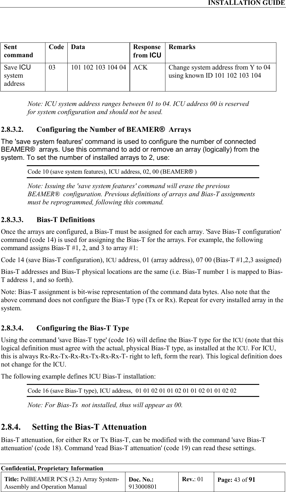
![INSTALLATION GUIDE Confidential, Proprietary Information Title: PolBEAMER PCS (3.2) Array System- Assembly and Operation Manual Doc. No.: 913000801 Rev.: 01 Page: 42 of 91 The following sections describe how to configure the system step-by-step. 2.8.3.1. Set ICU Operation Mode The ICU configuration setup can only be changed when the ICU is set to SLAVE mode. The default ICU configuration is AUTO. To switch to slave mode use 'save operation mode' command (code 05), with parameter 01. Note, however, that if the ICU communication is left unattended for longer than the time out, defined by 'save time out' command (code 36) [default value is 5 minute], the ICU will automatically switch back to AUTO mode. Only the following commands are available in AUTO mode: • Save operation mode (05) • Read operation mode (06) • Save control mode (07) • Read control mode (08) • Read array status (28) • Read BEAMER® status (29) • Read ICU status (30) In AUTO mode, any other command will be responded by an error message (code 34, data 01 xx xx xx xx). 2.8.3.1.1. Checking the ICU System Address and ICU ID The ICU system address and the ICU ID can be easily modified1, to suit your needs. To change the ICU address you should know the ICU ID. You can read the ICU system address and its ID as follows: Sent command Code Data Response from ICU Remarks Read ICU ID 02 00 X1 X2 X3 X4 Every ICU answers when addressed by 00 Read ICU system Address 04 X1 X2 X3 X4 X1 X2 X3 X4 Y Use ICU ID (X1 X2 X3 X4) to find ICU address (Y) 2.8.3.1.2. Changing the ICU System Address Caution: ICU ID is located on the unit label. The unit label is attached to the -ICU front panel (the fuse panel). The ICU ID is its physical number. Do not modify the ICU ID, unless authorized by Celletra engineering support. Once the ICU ID and system address are known, you can easily modify the system address to any other value. The following sequence demonstrates how to change the ICU system address from Y to 04, using known ICU ID 101 102 103 104. 1 ICU ID cannot be changed in operation mode. Issuing command code 01 in operation mode will produce an error message.](https://usermanual.wiki/Celletra/C-BPB.Users-Manual/User-Guide-166707-Page-42.png)
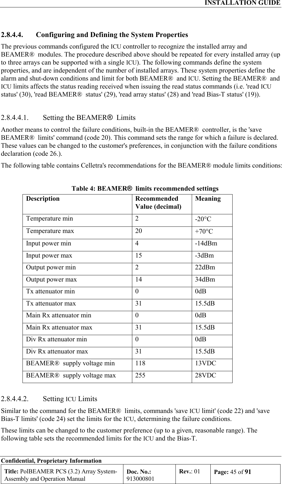
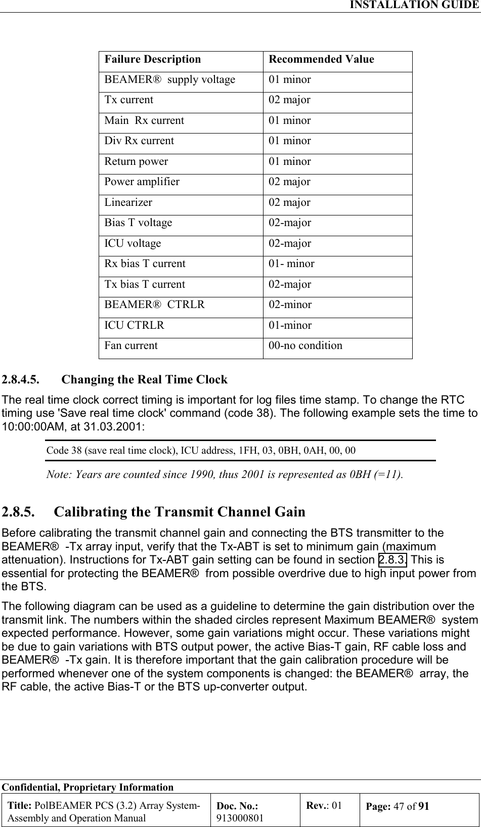
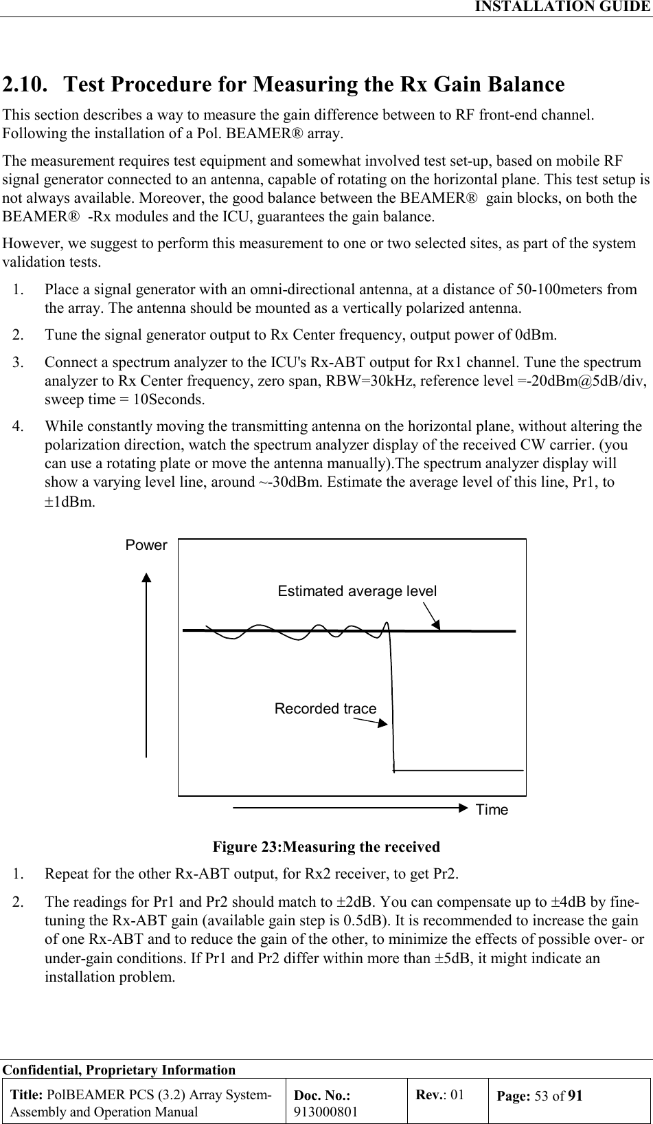
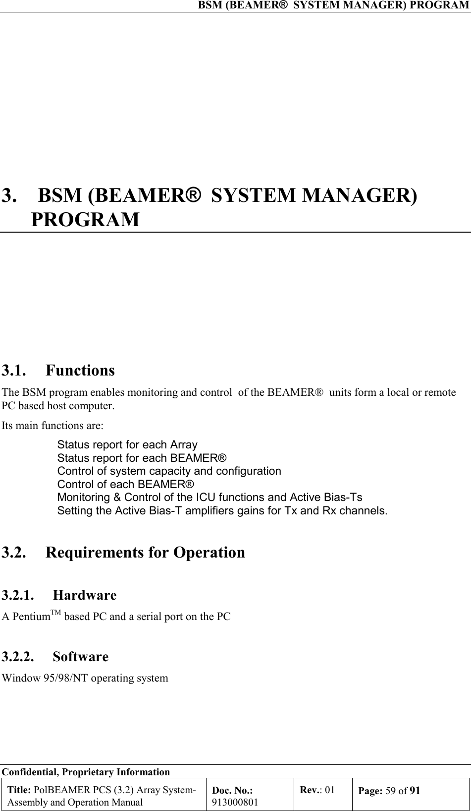
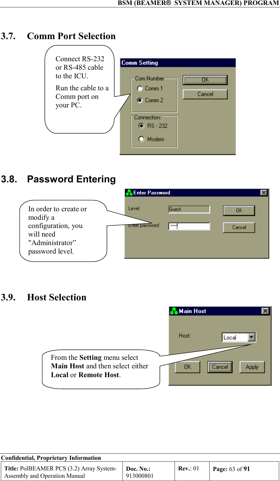
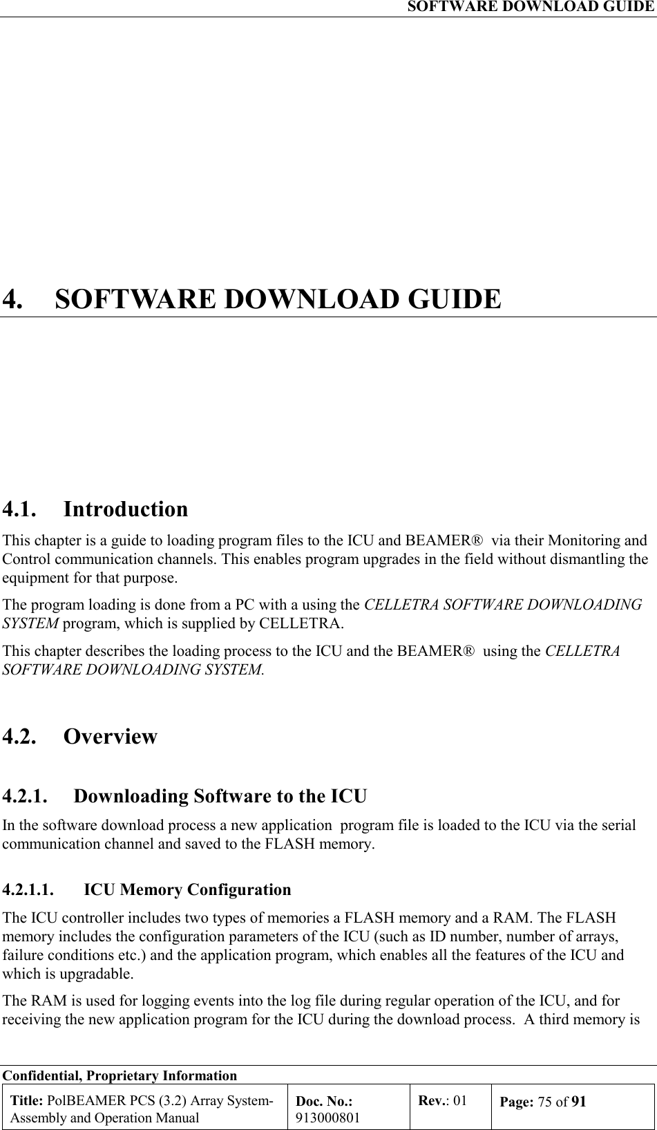
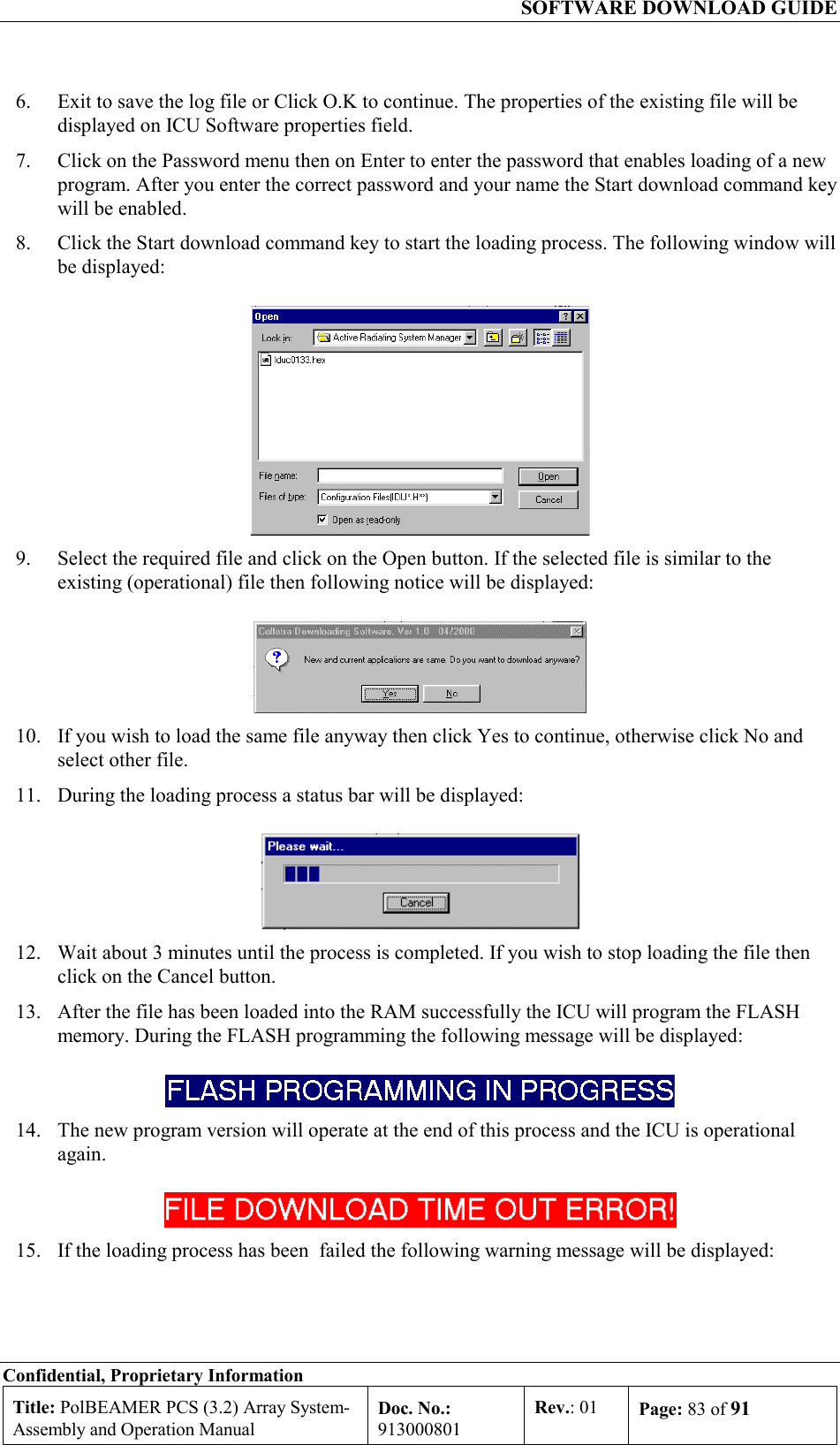
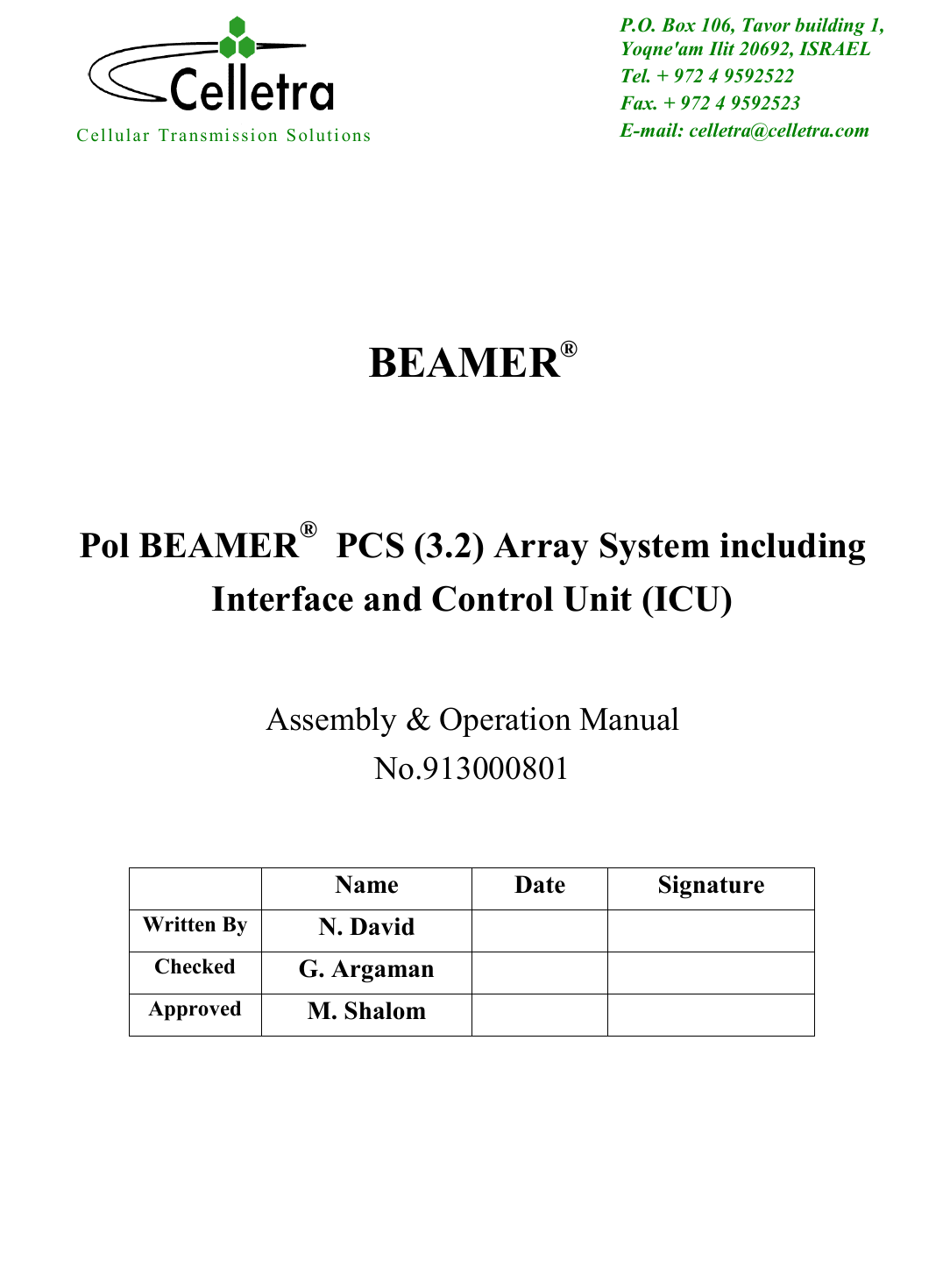
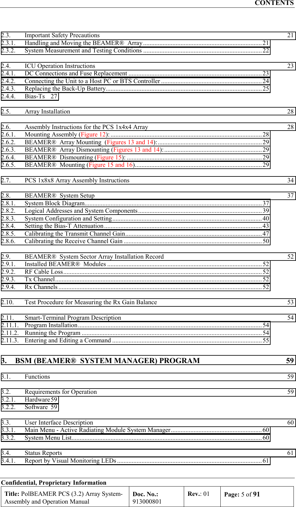
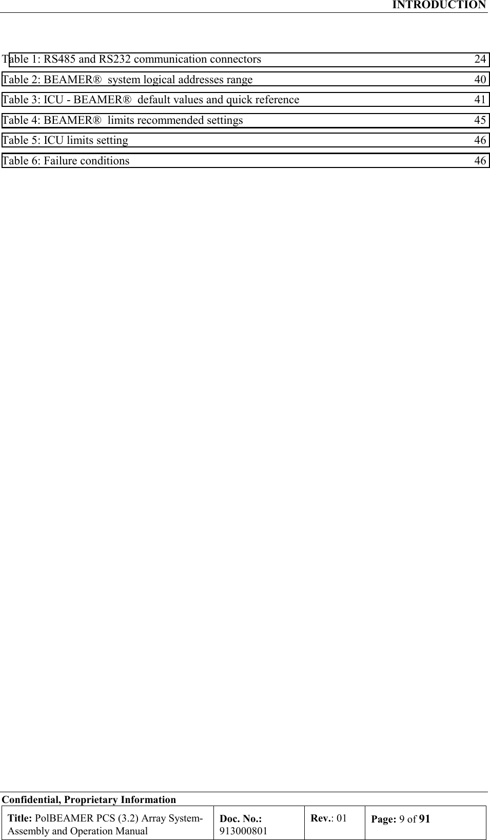
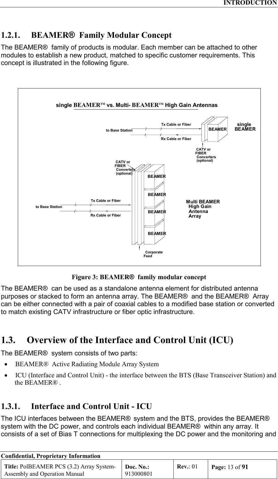
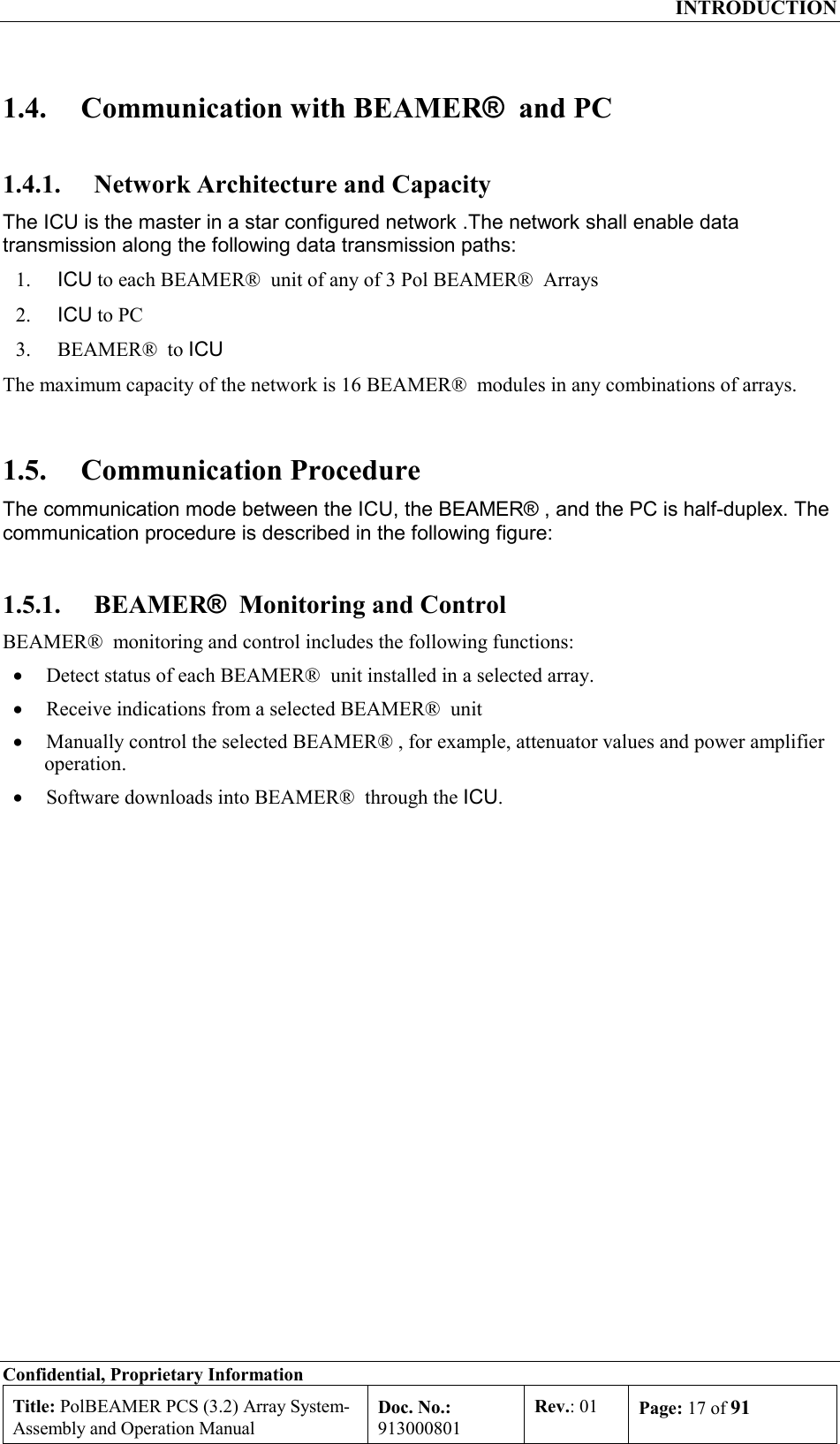
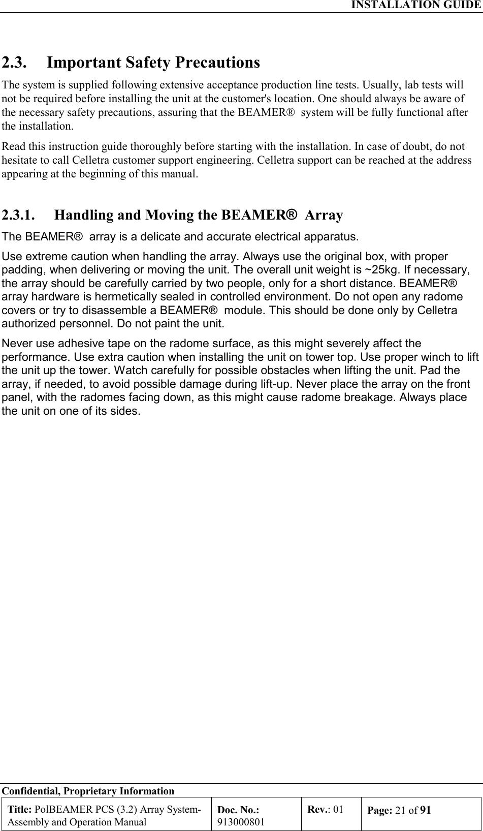
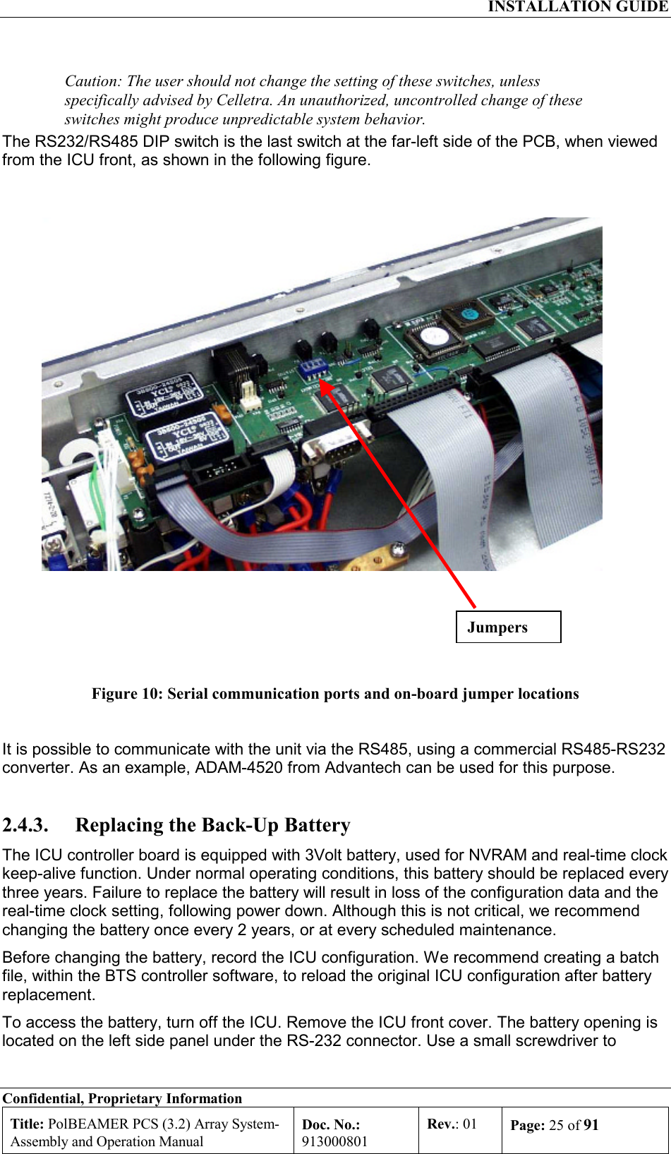
![INSTALLATION GUIDE Confidential, Proprietary Information Title: PolBEAMER PCS (3.2) Array System- Assembly and Operation Manual Doc. No.: 913000801 Rev.: 01 Page: 48 of 91 BeamerArray[G=13.5dBi]G1:4DividerLoss=LGABTBTSInputPinPout (max)=10dBmG=30±1dBGC=0 to15.5dBL=0 to6dBPout (max)=34dBmG=37±0.5dBGC=0 toEIRP=53.5dBm(max)Combinedin the AirBeamer 4GGBeamer 3GBeamer 2Beamer1-20dbmPin=-5dBm to -20dBm+8dbmCoax15.5dB+40dbm[L=6db]+3dbm-3dbm Figure 21: Tx link budget example 2.8.5.1. Estimating the Required Tx-ABT Gain The purpose of this procedure is to verify that the BEAMER® system available gain is sufficient to cover the expected RF losses, before starting the actual Tx calibration.](https://usermanual.wiki/Celletra/C-BPB.Users-Manual/User-Guide-166707-Page-48.png)
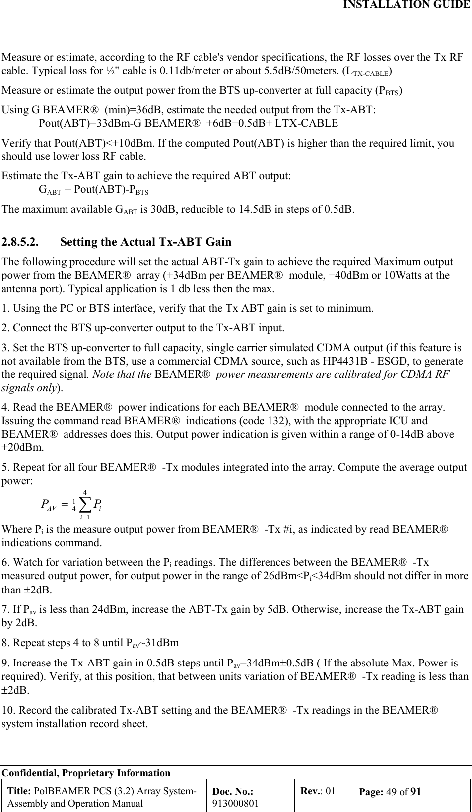
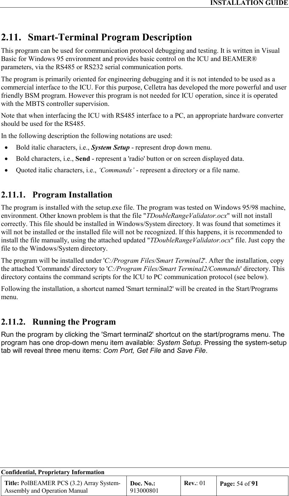
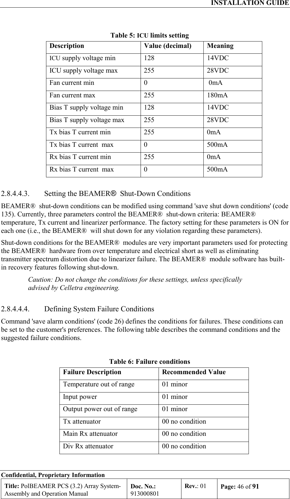
![INSTALLATION GUIDE Confidential, Proprietary Information Title: PolBEAMER PCS (3.2) Array System- Assembly and Operation Manual Doc. No.: 913000801 Rev.: 01 Page: 50 of 91 2.8.6. Calibrating the Receive Channel Gain The Pol. BEAMER® Rx array gain distribution is illustrated in the following figure. It is assumed that the RF cable loss is 6dB. The shaded circles represent the received system noise level, at maximum available gain and at 1.25MHz bandwidth. BeamerArray[G=13.5dBi]2:1RearCombiner[L=0.3dB]RF CoaxLoss=LGABTBTSG=6±1dBGC=0 to 15.5dBL=3 to 8dBG=30±1dBGC=0 to 15.5dB2:1Rear[L=0.3dB]BTS downConverterRX2RX1Noise PinInput-82dbm-88dbmNoise Figure=4dbCombiner-82dbm-112dbmBeamer-82dbm Figure 22: Rx channel gain distribution example The main factors to consider, when calibrating the Rx channels are as follows: The total system gain should be high enough to assure that the system input noise level will be driven beyond the down-converter output AGC nominal bias point, when the BEAMER® plus BTS down converter gain is at the maximum available gain. The total BEAMER® system gain should not be too high, to avoid excessive reduction of the system IIP3 thus increasing the system susceptibility to interference. As a rule of thumb, an excess gain of 6-10dB beyond the minimum required gain from rule 1 is the maximum required gain for rule 2. For efficient diversity operation, even at relatively low signal to noise ratio, the two Rx channels gains should be balanced to ±2dB.](https://usermanual.wiki/Celletra/C-BPB.Users-Manual/User-Guide-166707-Page-50.png)