Celletra C-ENCR-CBS021 Cellular CellEnhancer Unit User Manual Transmit Diversity Add On System
Celletra Ltd. Cellular CellEnhancer Unit Transmit Diversity Add On System
UserManual.wiki
>
Celletra
>
C ENCR CBS021 User Manual
manual
Navigation menu
Upload a User Manual
Namespaces
Wiki Guide
HTML
PDF
Info
Views
User Manual
Discussion / Help
Navigation
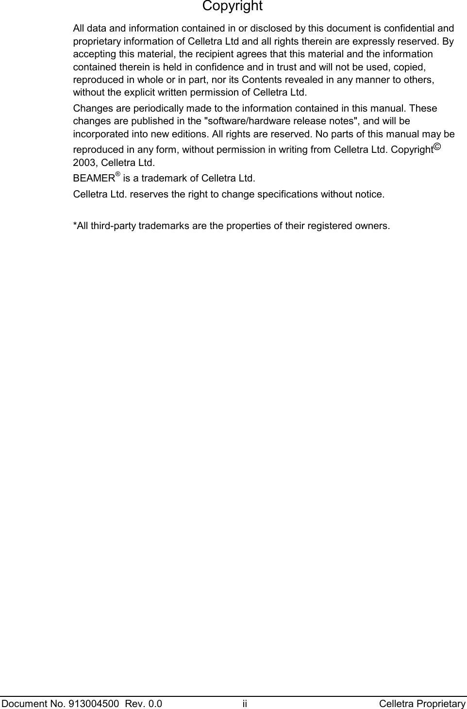
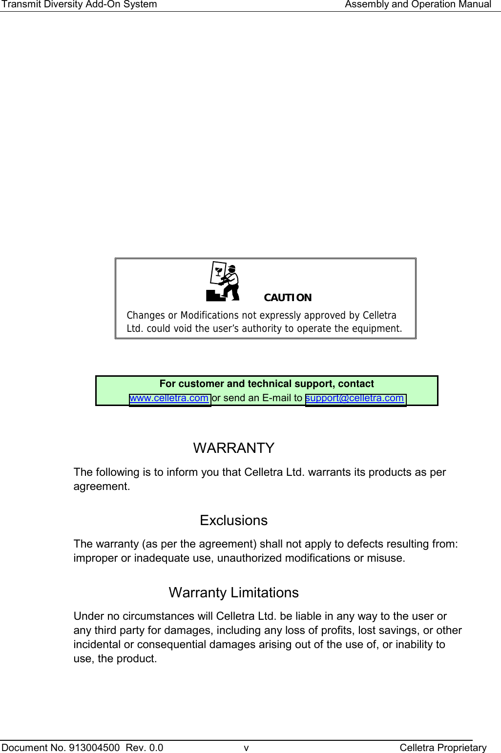
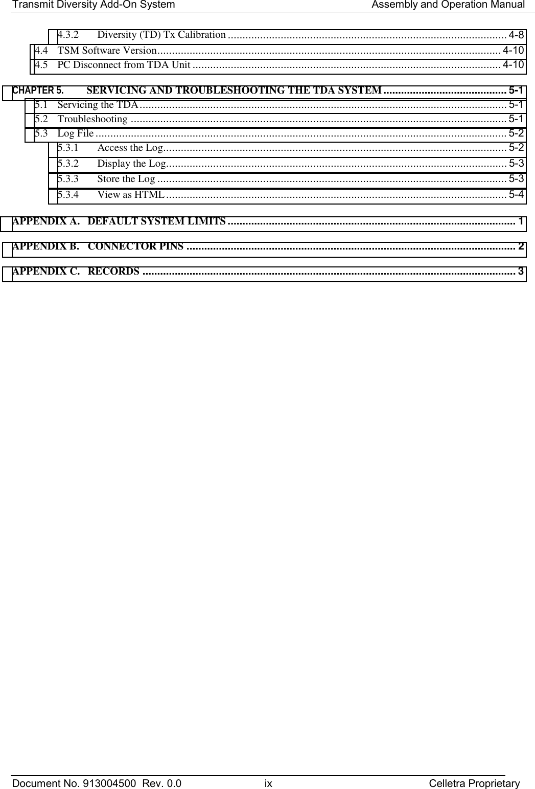
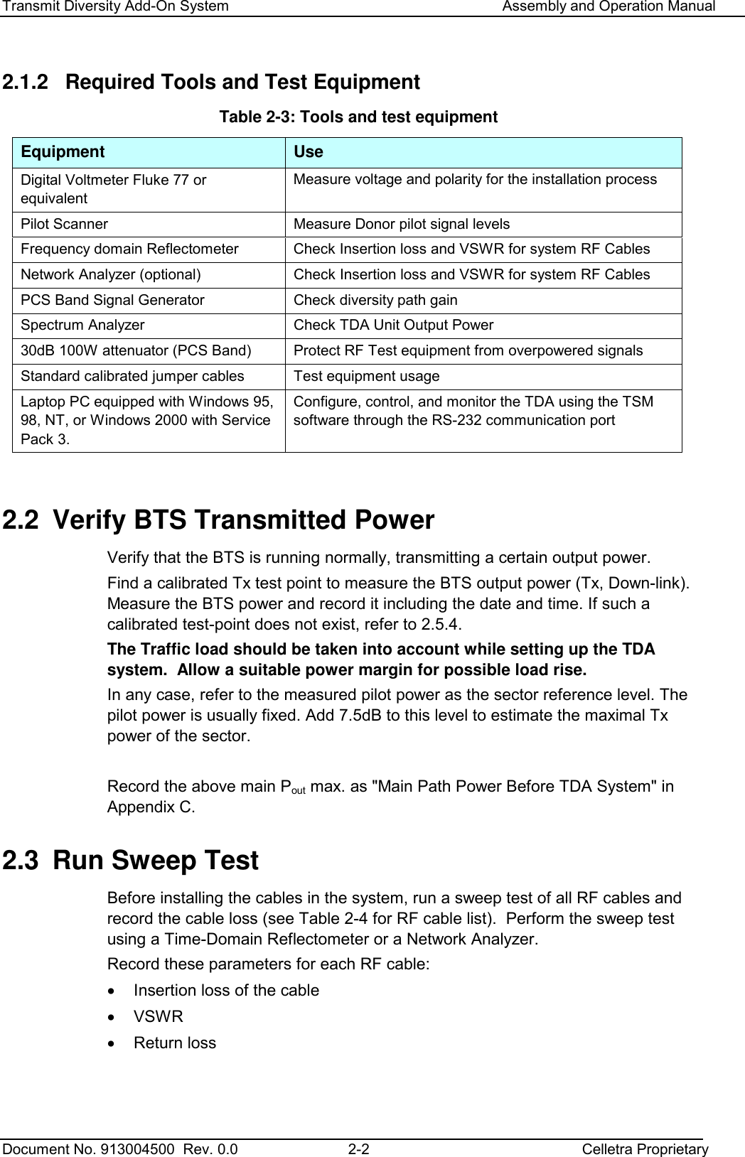
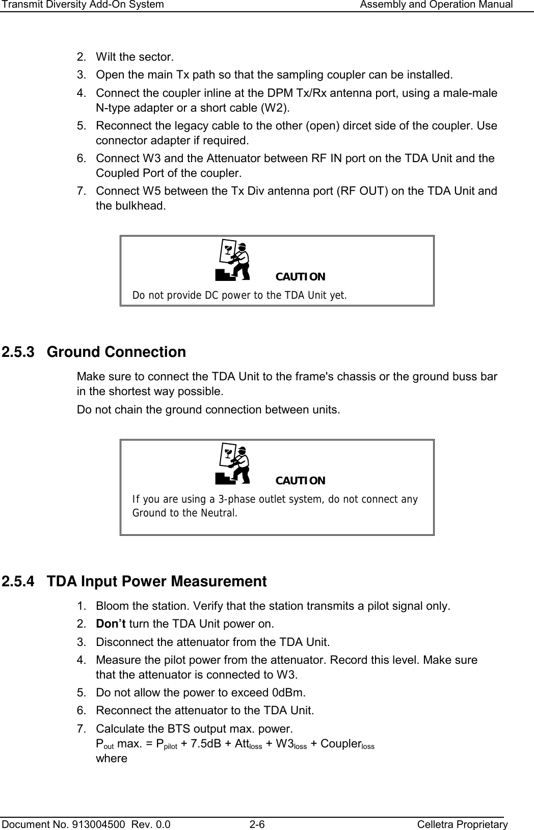
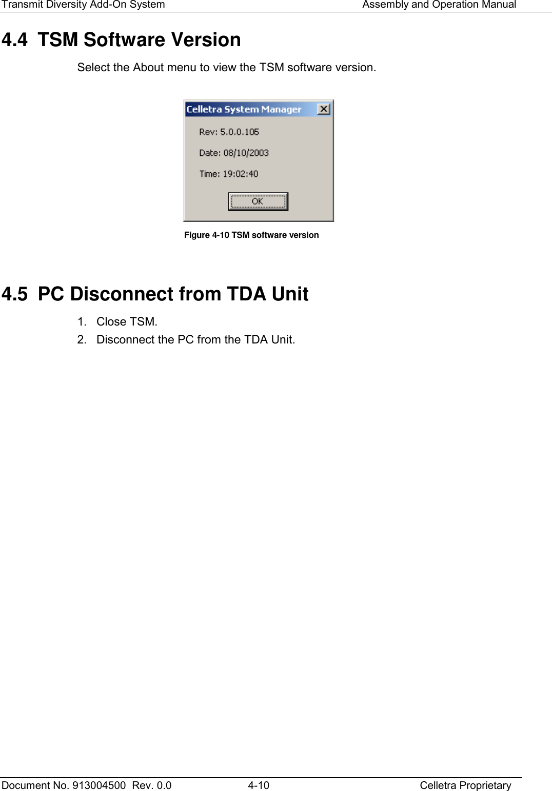
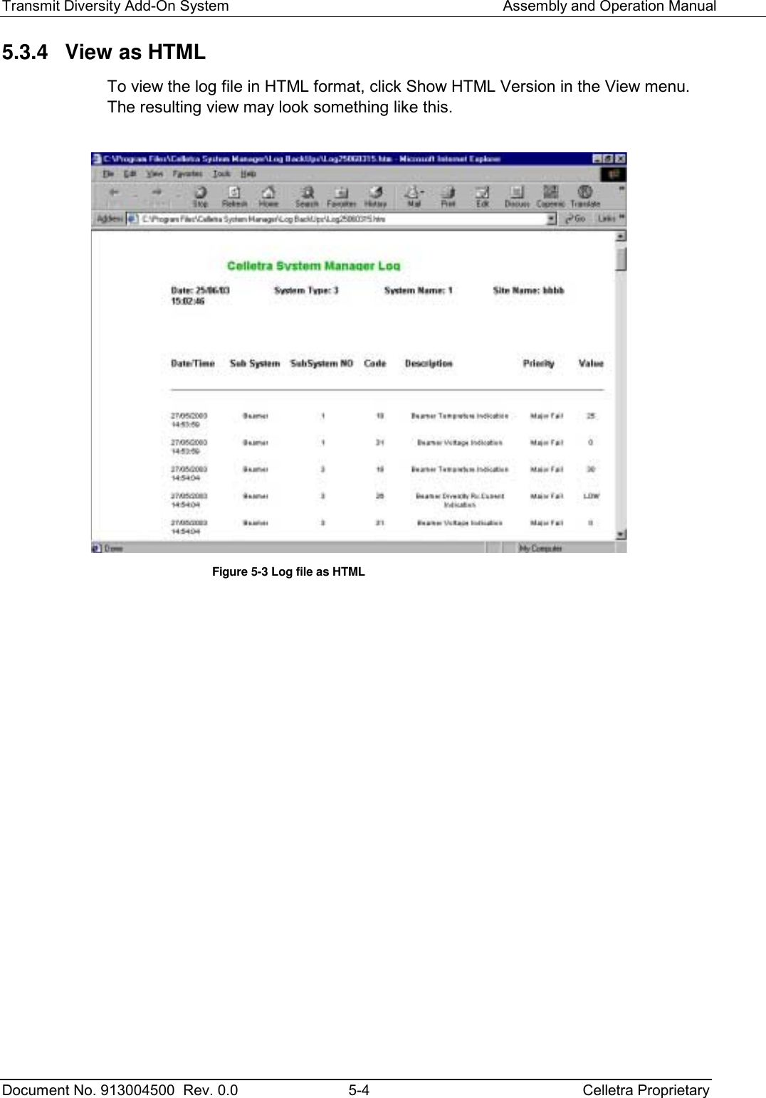
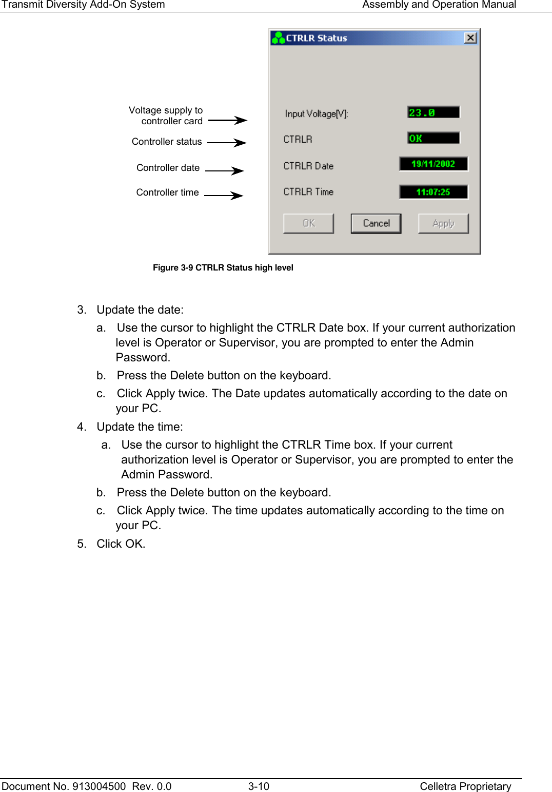
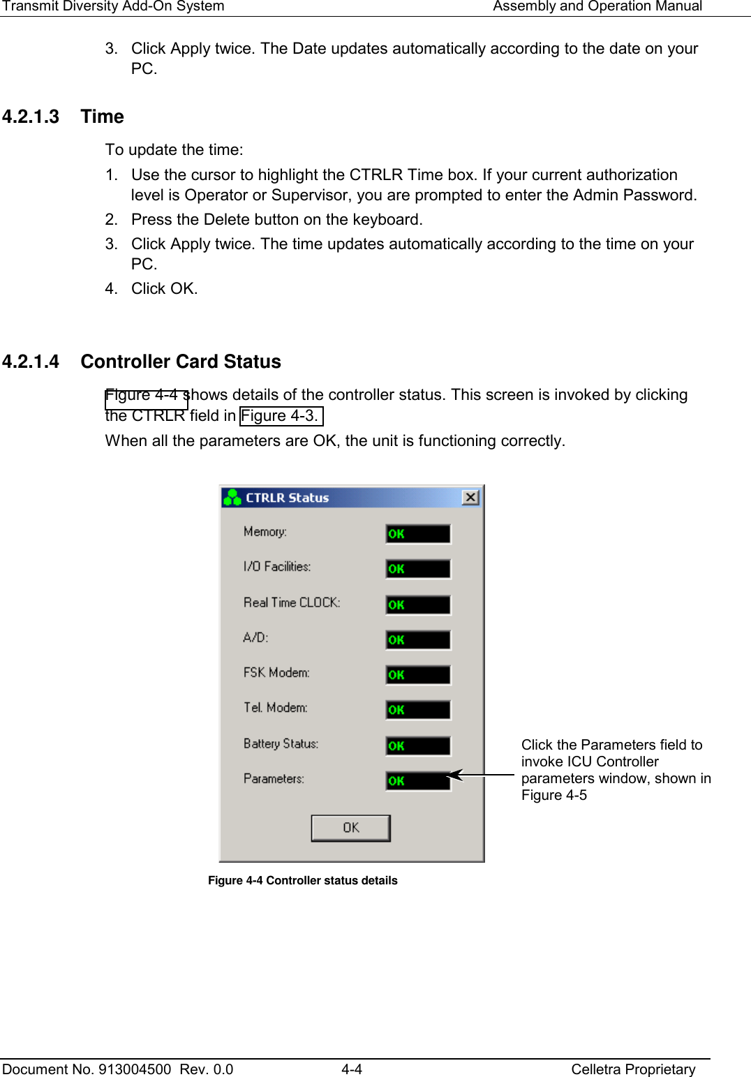
![Transmit Diversity Add-On System Assembly and Operation Manual Document No. 913004500 Rev. 0.0 2-7 Celletra Proprietary Attloss = 20dB W3loss = W3 Insertion loss, as measured in Table 2-4 [dB] Couplerloss = 30dB Pout max. = Ppilot + 7.5dB + 20dB + W3loss + 30dB Pout max. = _______dBm Record the above main Pout max. as "Main Path Power After TDA System" in Appendix C. 2.6 Prepare the Electrical Power Connections CAUTION Power to the units must be supplied according to the safety standards in the corresponding country (grounded outlets, circuit breaker, conduits, etc.). Check the power cable before connecting it to the units. NOTE: Fuse is located on the TDA Unit front panel. Ensure the fuse is pushed in. 1. Supply power to the TDA Unit. 2. Verify that the unit is working properly by connecting directly with a PC as explained in the next Chapter.The three fans at the front panel are working only in case of excessive internal temprature. Thus, in an airconditioned site they may stay idle for long time priods.](https://usermanual.wiki/Celletra/C-ENCR-CBS021/User-Guide-440638-Page-18.png)
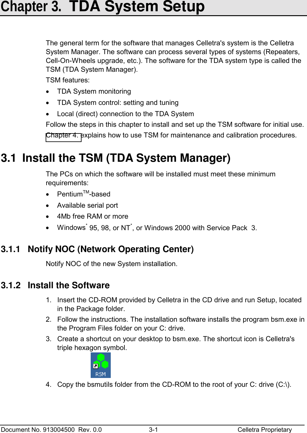

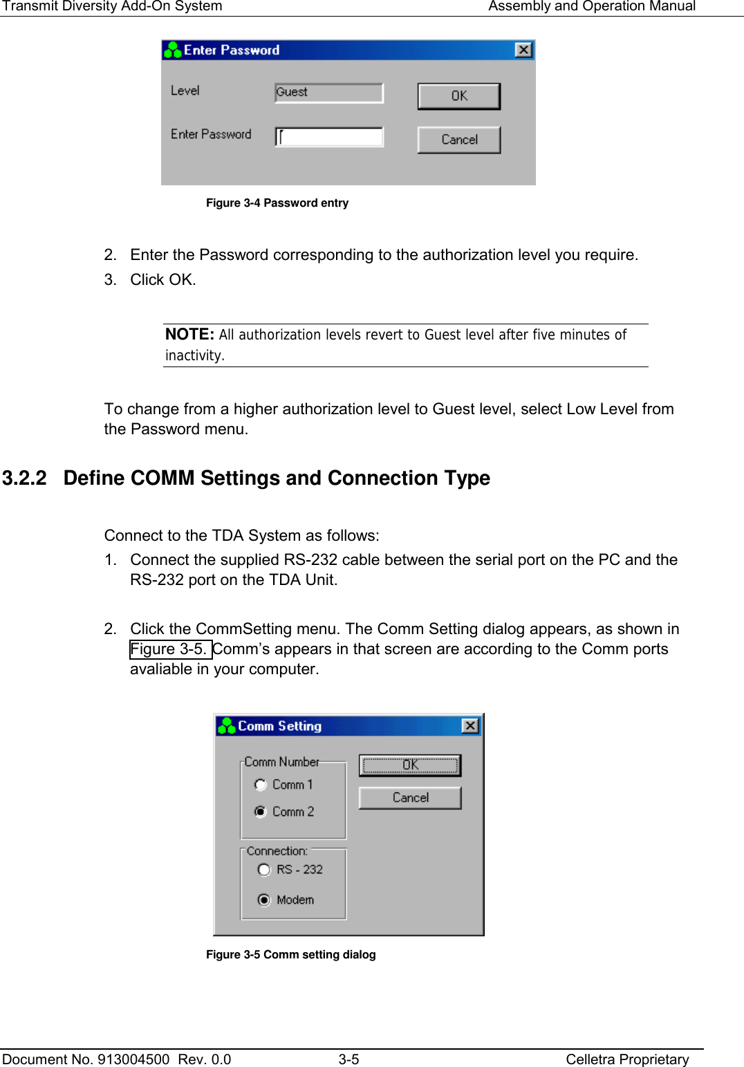
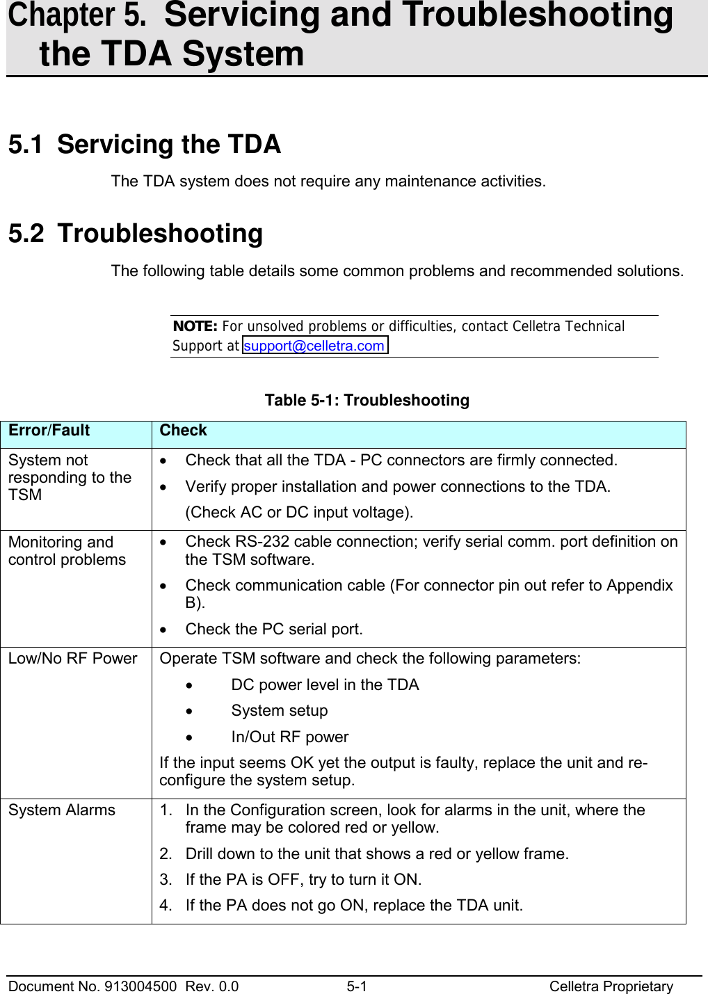
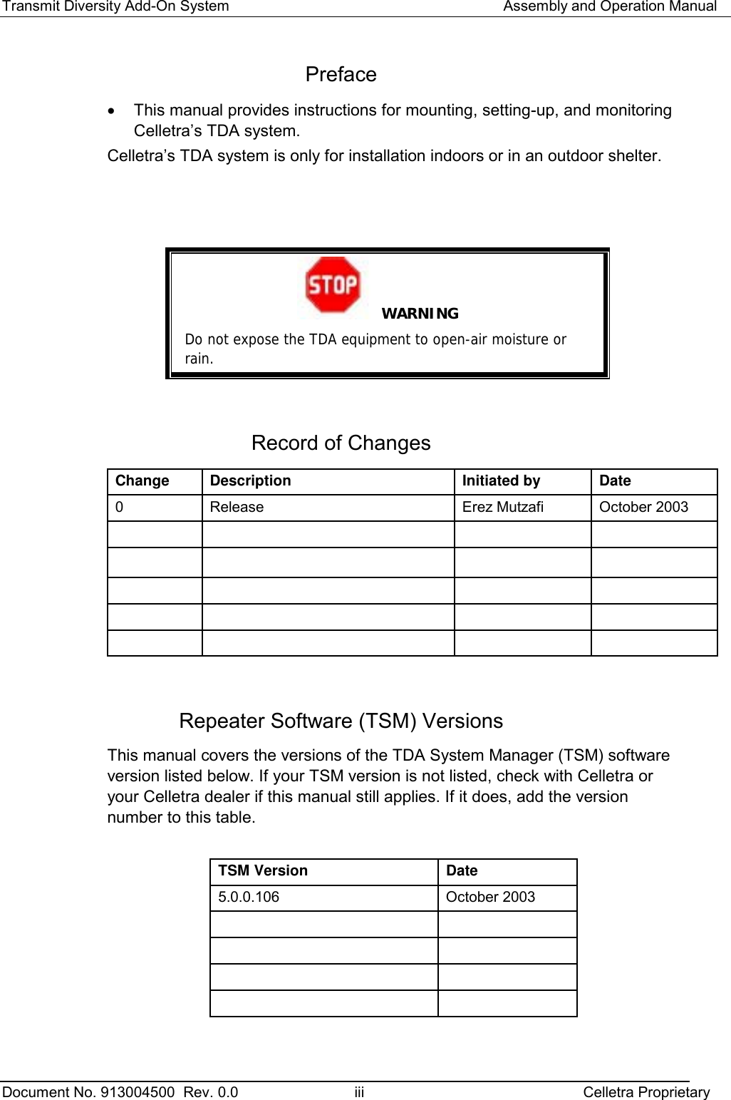
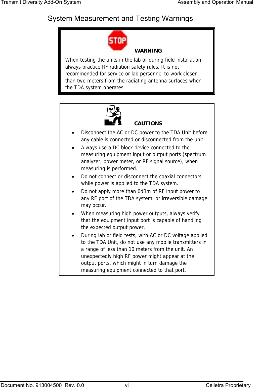
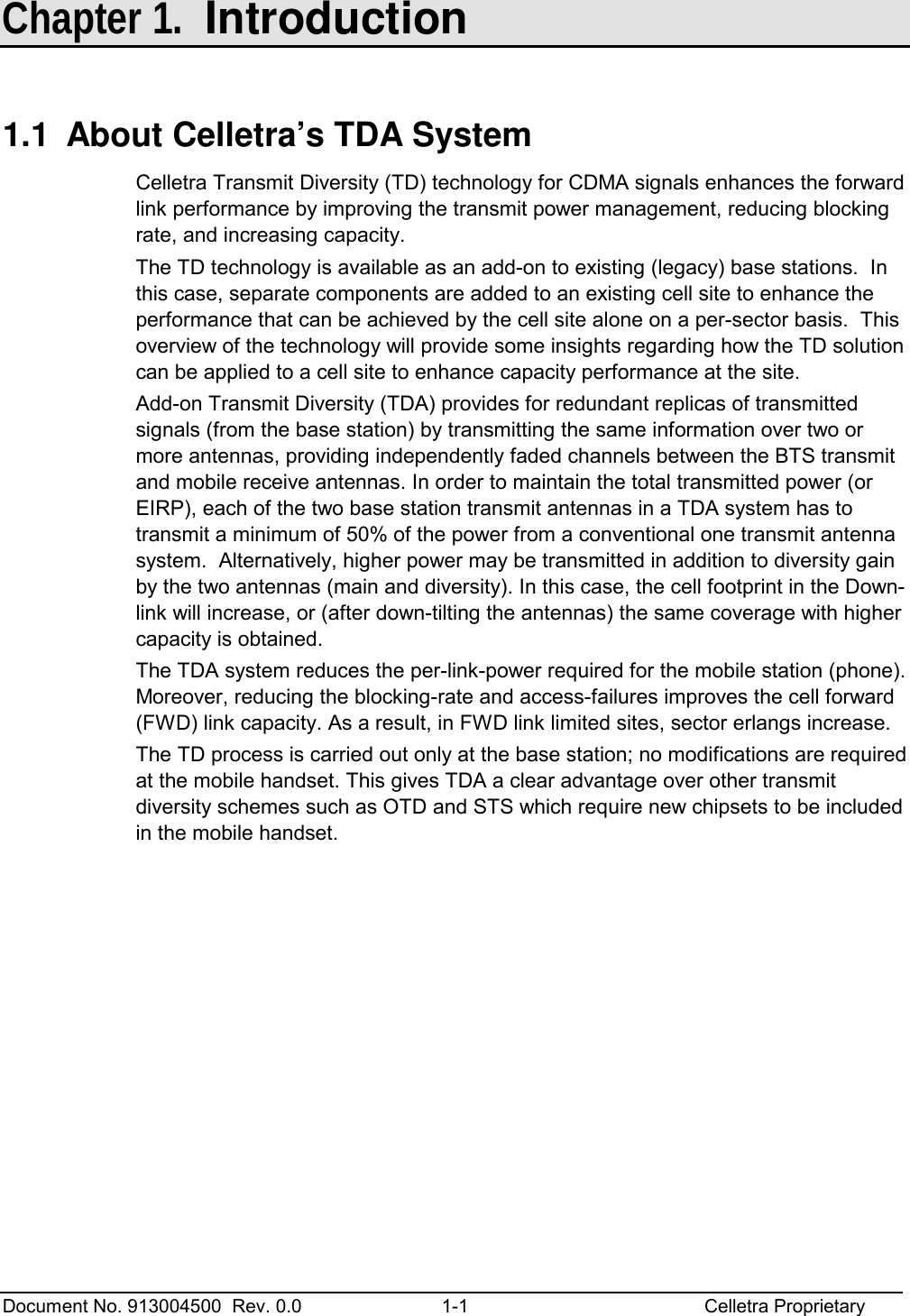
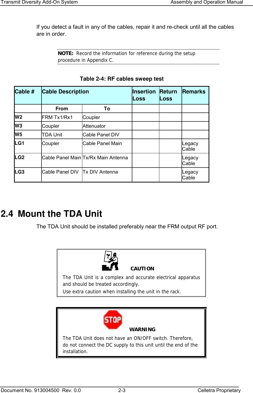
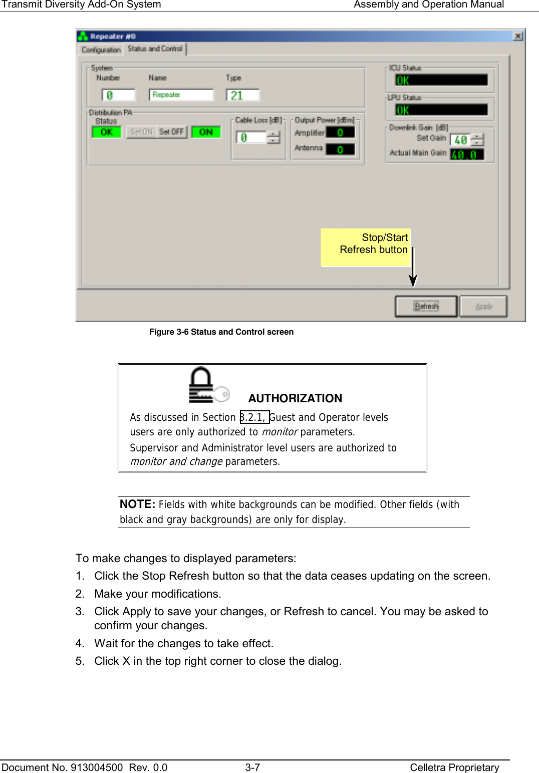
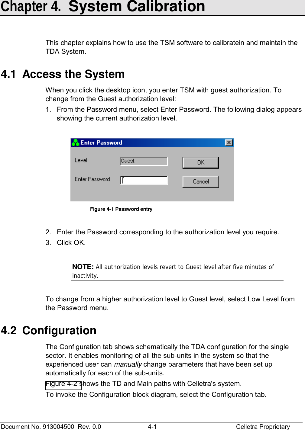
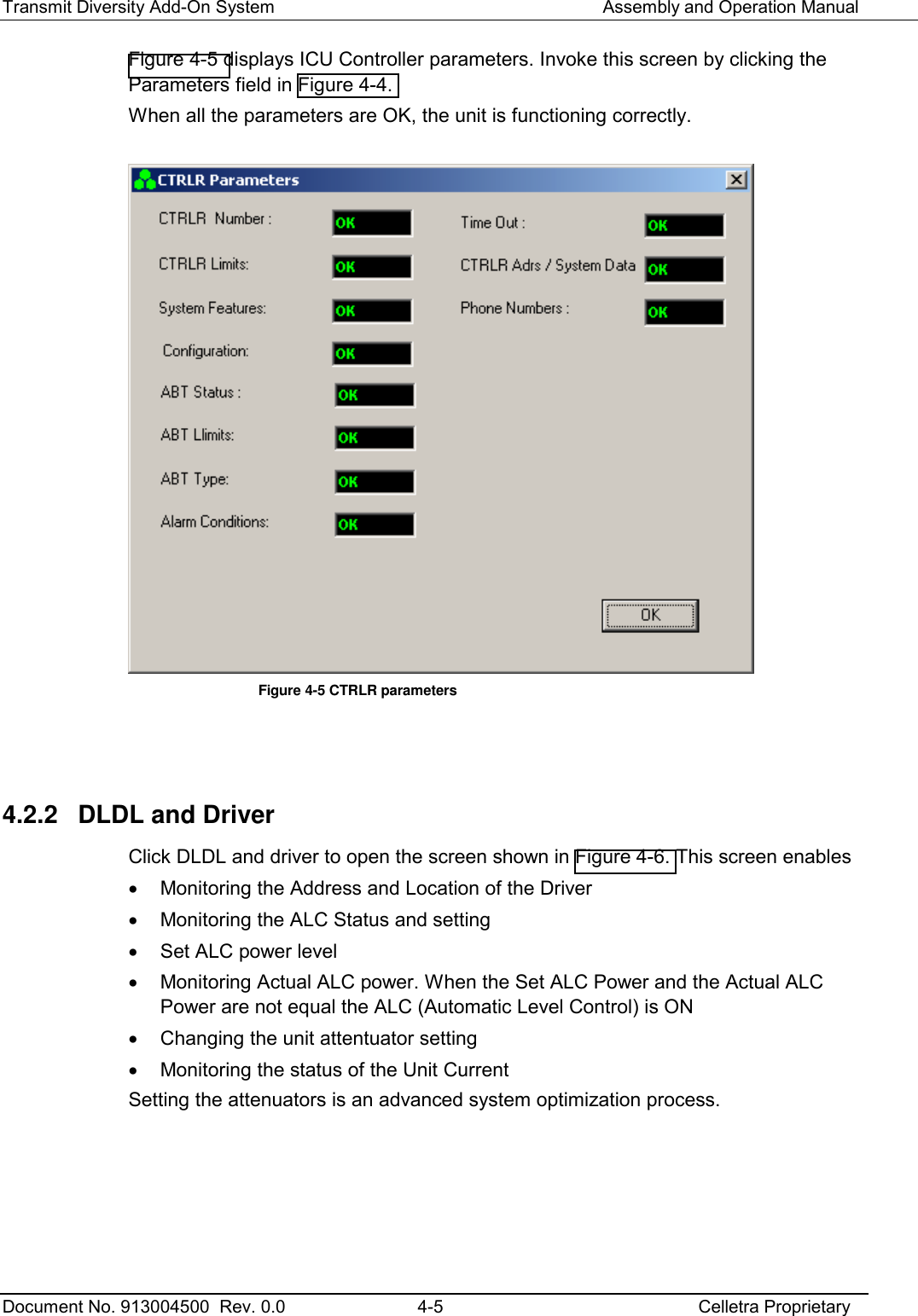
![Transmit Diversity Add-On System Assembly and Operation Manual Document No. 913004500 Rev. 0.0 3-6 Celletra Proprietary 3. Under Comm Number, click the radiobutton corresponding to your PC modem port. 4. Under Connection, click the RS-232. Modem option is not is use. 5. Click OK. 3.3 Navigate the TDA System Setup and Configuration Windows All TDA System setup and configuration functions are implemented from a single menu option. To access the TDA System setup, click the System menu. The following tabs appear. Configuration tab For monitoring. This dialog shows a block diagram of the TDA sysem, where each unit in the block diagram (PA, Driver,…) provides access to corresponding monitoring options. Section 4.2 fully explains this block diagram and the data it displays. Status and Control tab For setup. Contains site information, gains, cable loss definitions, and power monitoring. See Section 3.3.1. 3.3.1 Status and Control Figure 3-6 shows the dialog that appears when you click the Status and Control tab. The System Type for the TDA system is 21. With this tab you can change setup parameters such as • Site Information • Cable loss • PA status (Distribution PA) • PA ON/OFF • PA output power (‘Output Power [dBm] Amlifier’) • Output power to antenna (‘Output Power [dBm] Antenna’) • Downlink Gain [dB] • Actual Main Gain (monitoring) • ICU status • LPU ststus](https://usermanual.wiki/Celletra/C-ENCR-CBS021/User-Guide-440638-Page-24.png)
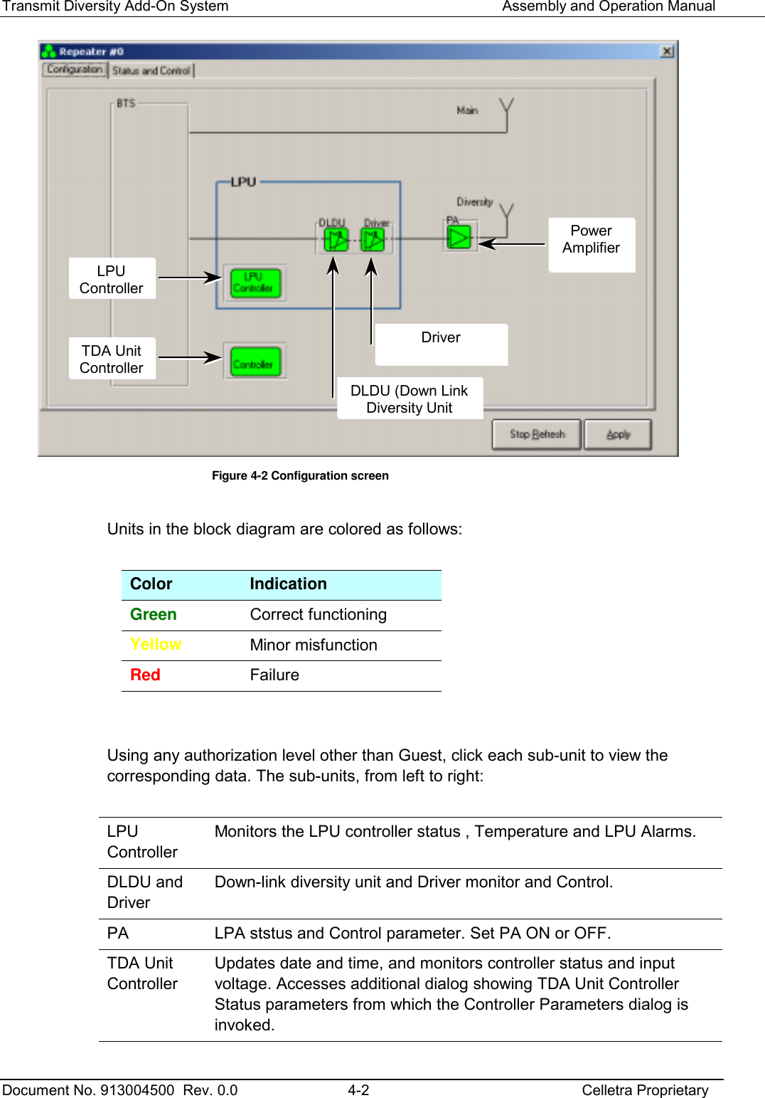
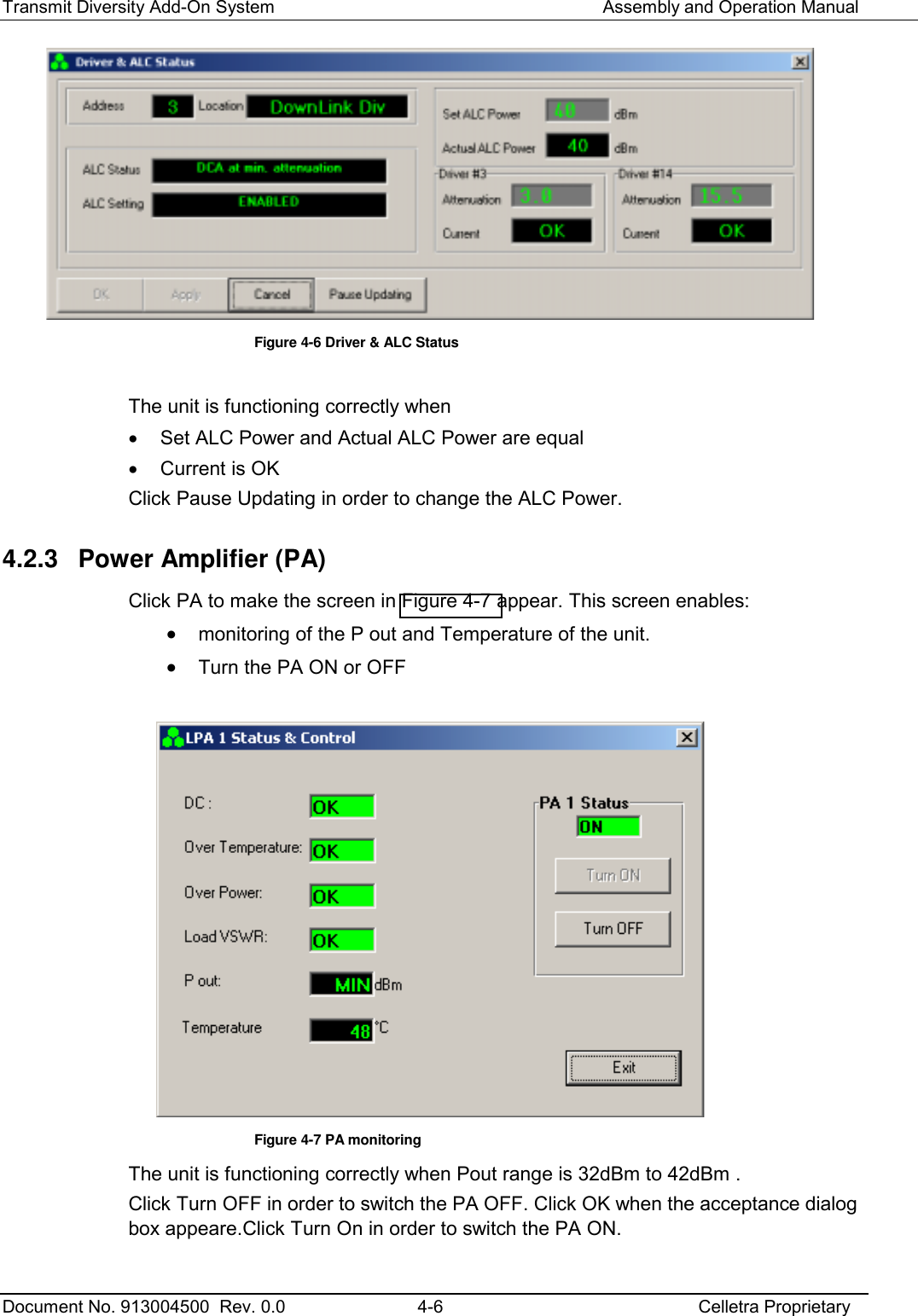
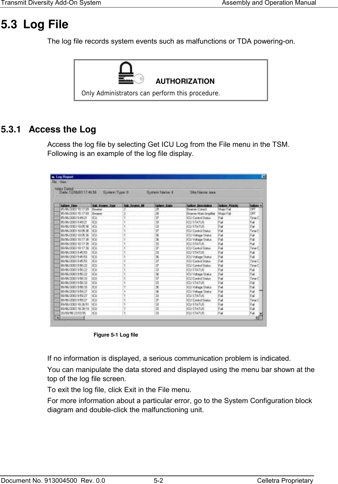
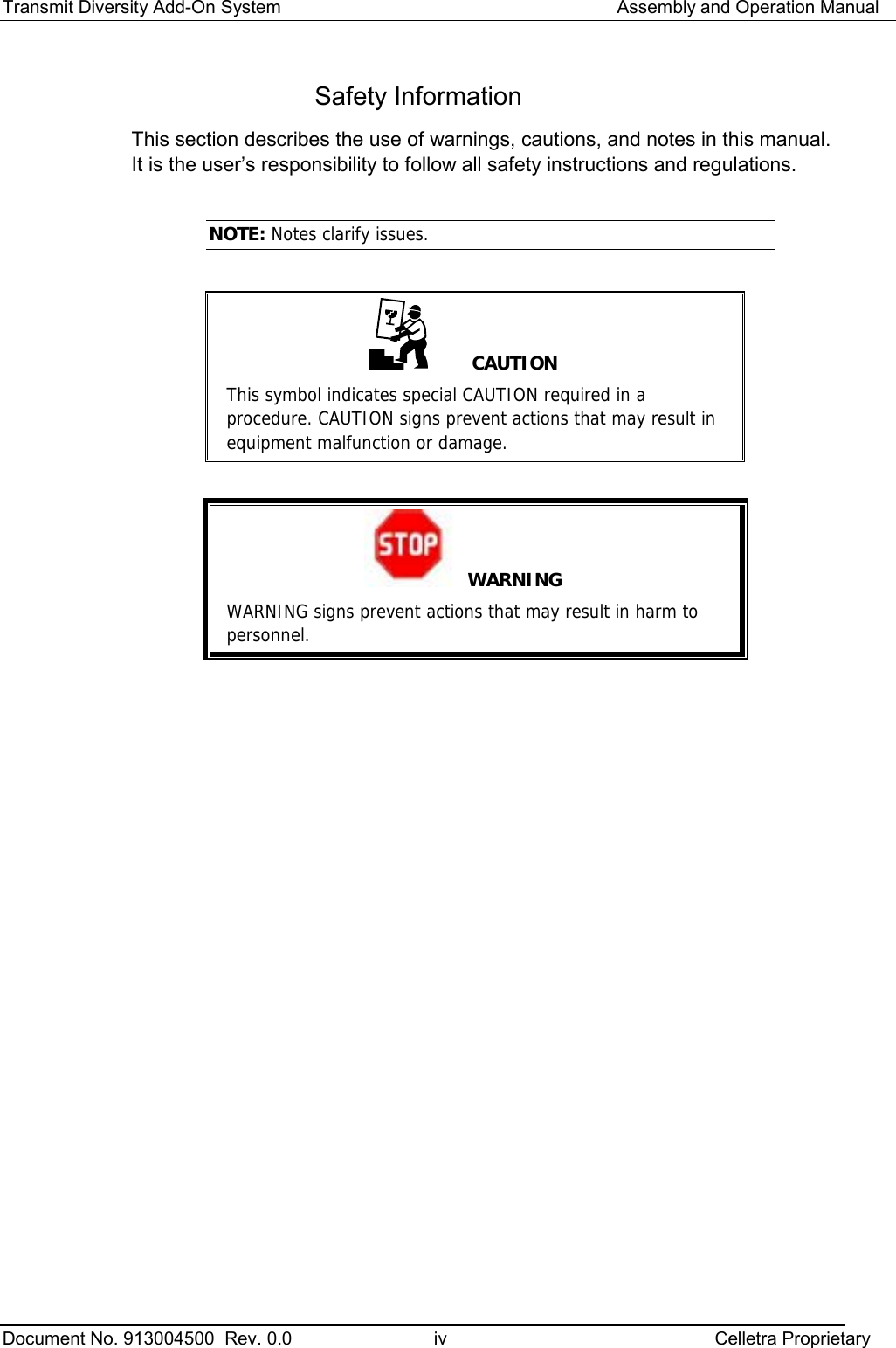
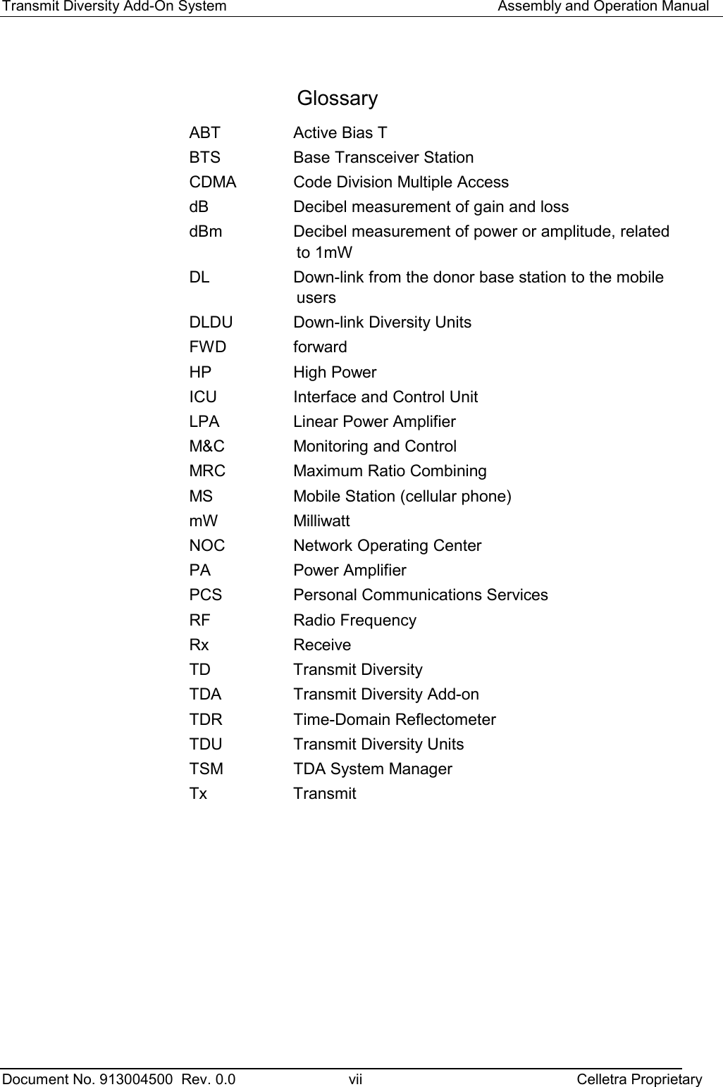
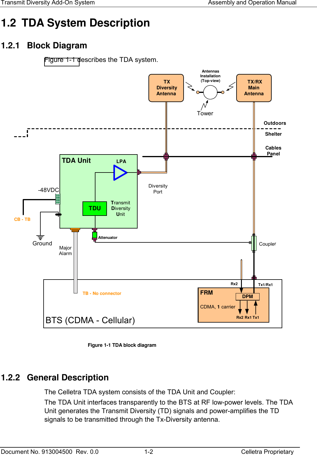
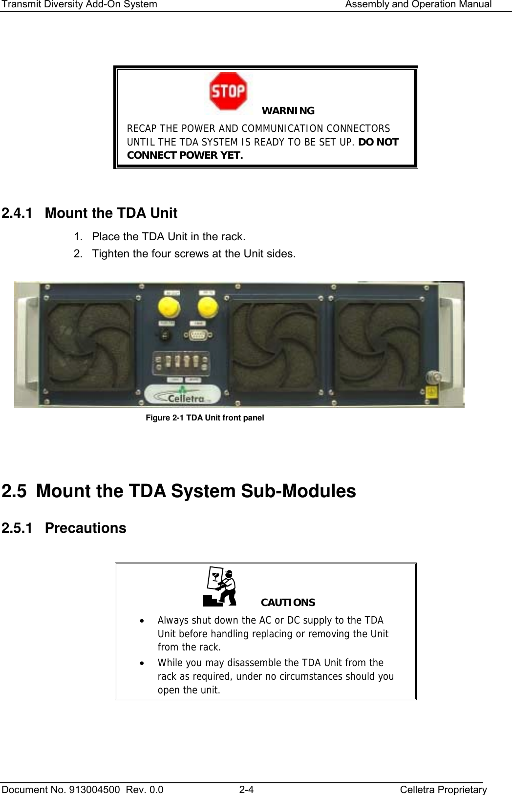
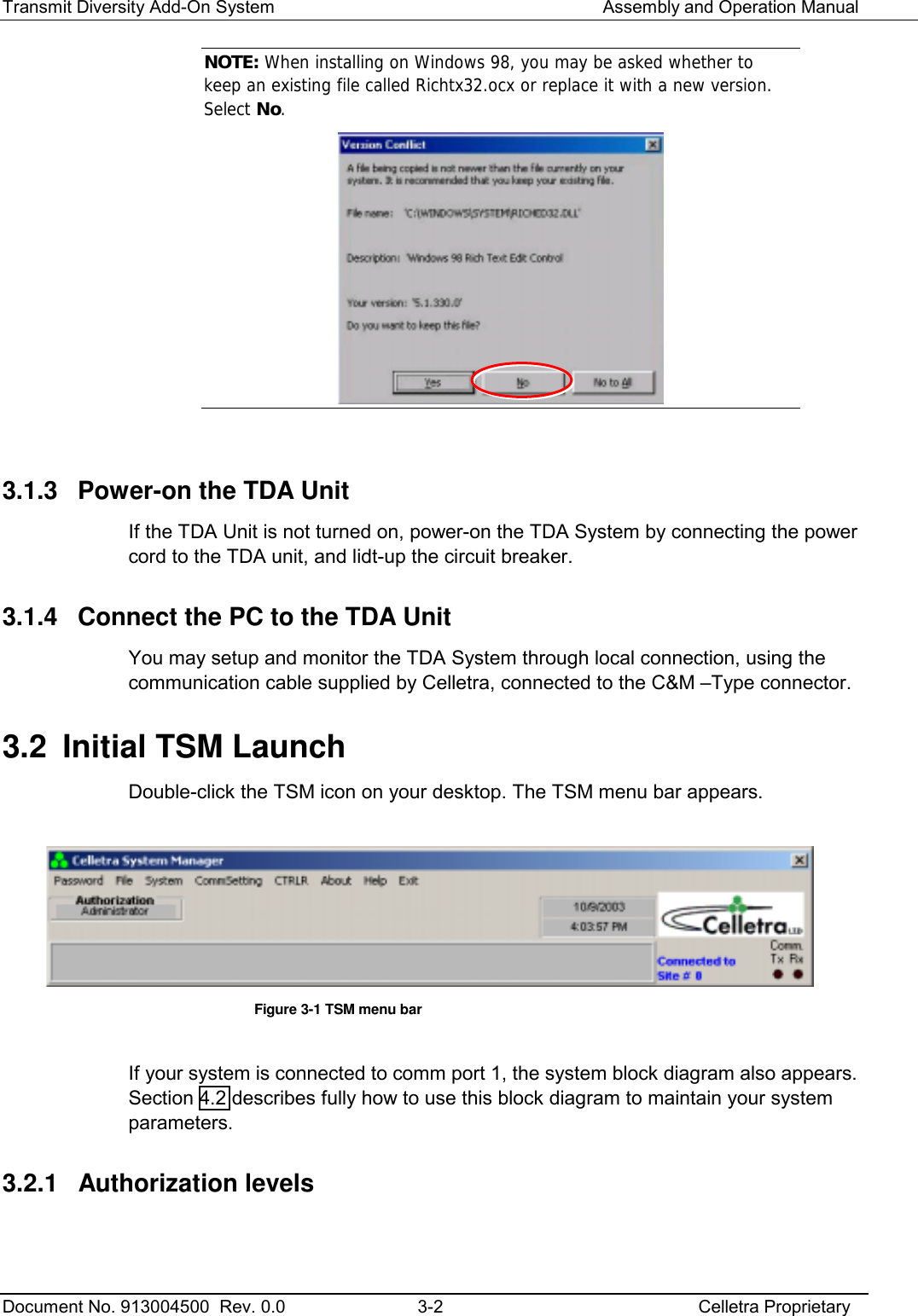
![Transmit Diversity Add-On System Assembly and Operation Manual Document No. 913004500 Rev. 0.0 4-8 Celletra Proprietary TDA UnitBTS (CDMA - Cellular)TransmitDiversityUnit TX DiversityAntennaTx1/Rx1OutdoorsShelterFRMCouplerDPMRx2 Rx1 Tx1CDMA, 1 carrierTDU-48VDCMajorAlarmN-MN-MN-MN-MTB - No connectorW1W2W37-F7-MW5W6N-M or 7-M7-F7-MCablesPanelGroundLPACB - TBW7 TX/RXMainAntennaAntennasInstallation(Top-view)TowerRx2DiversityPortAttenuatorN-MN-FPowerMeasurementEquipmentLG3 LG2LG1TDA Gain Figure 4-8 Tx measurements setup 4.3.2 Diversity (TD) Tx Calibration Calibrate the diversity path Tx power. 1. Click the Status and Control tab (Section 3.3.1). 2. Enter the Cable Loss [dB] (W5) according to Table 2-4, W5 Insertion loss [dB]. 3. Read the Antenna “Output Power [dBm]” from the TSM screen. Antenna Power [dBm] = Amplifier Power [dBm] – Cable Loss [dB] Where the cable loss is a positive value in dB.](https://usermanual.wiki/Celletra/C-ENCR-CBS021/User-Guide-440638-Page-36.png)
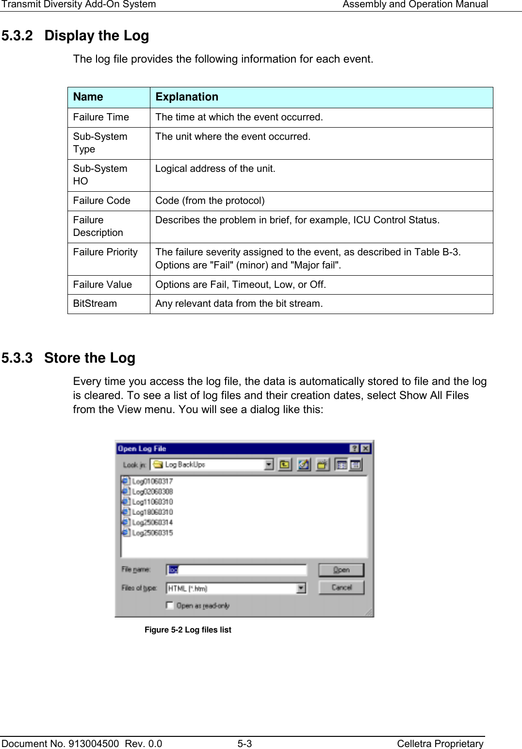
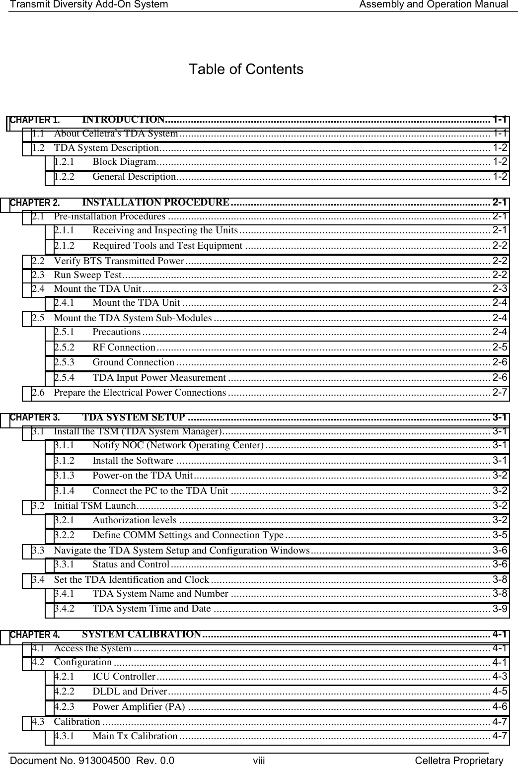
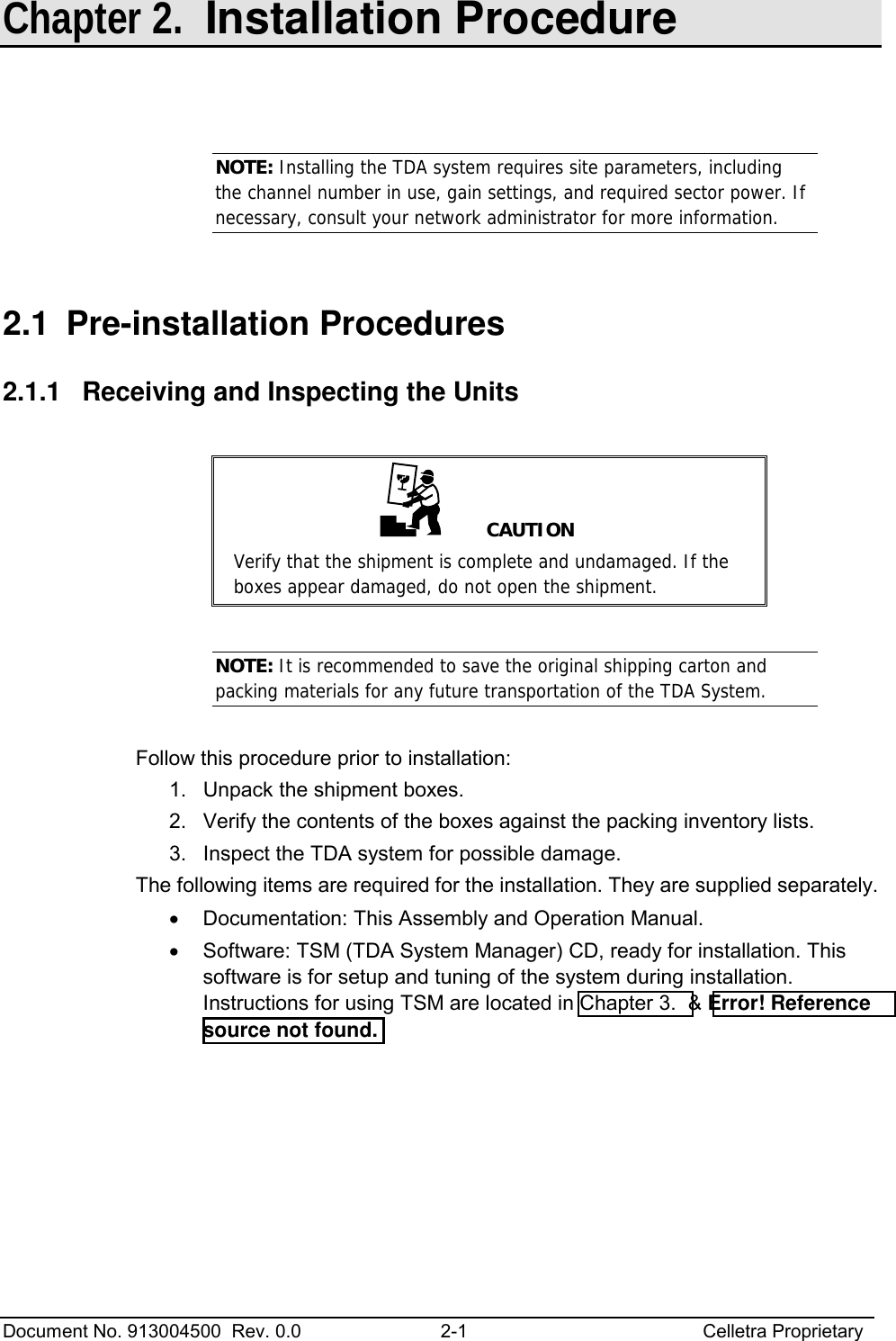
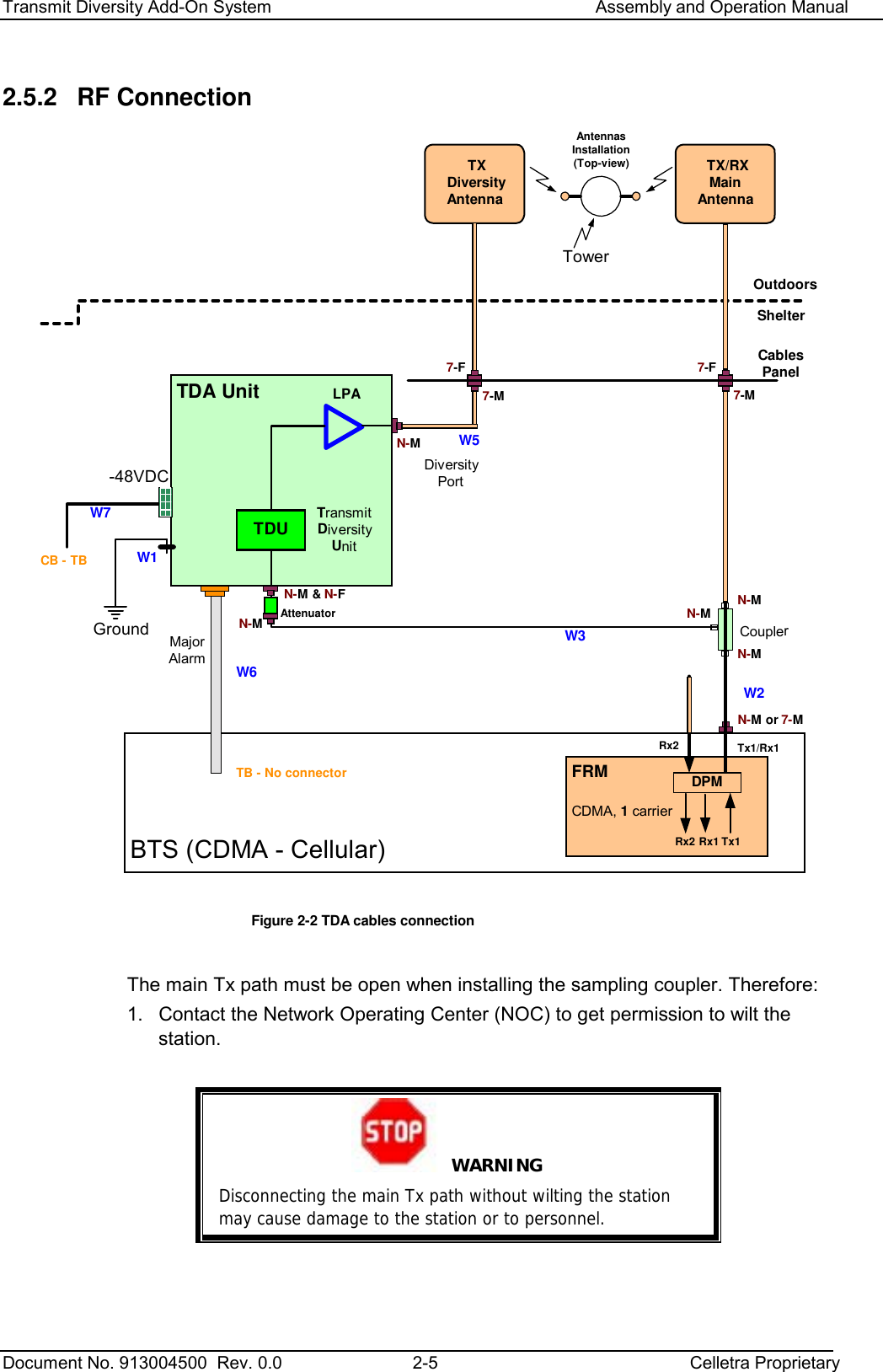
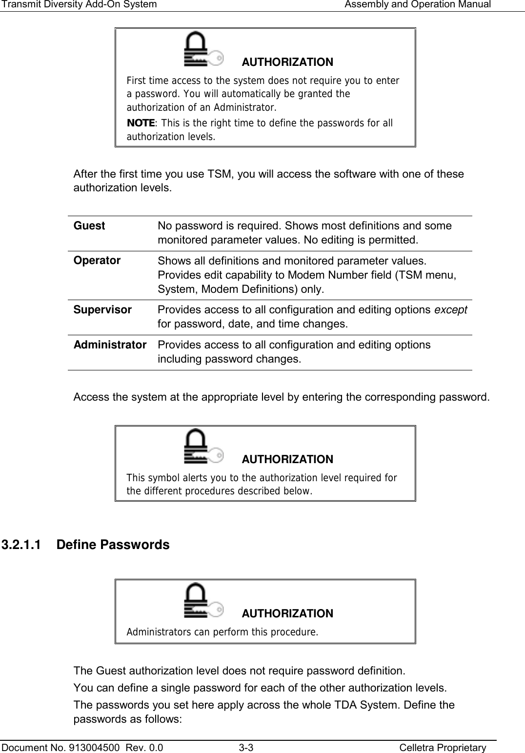
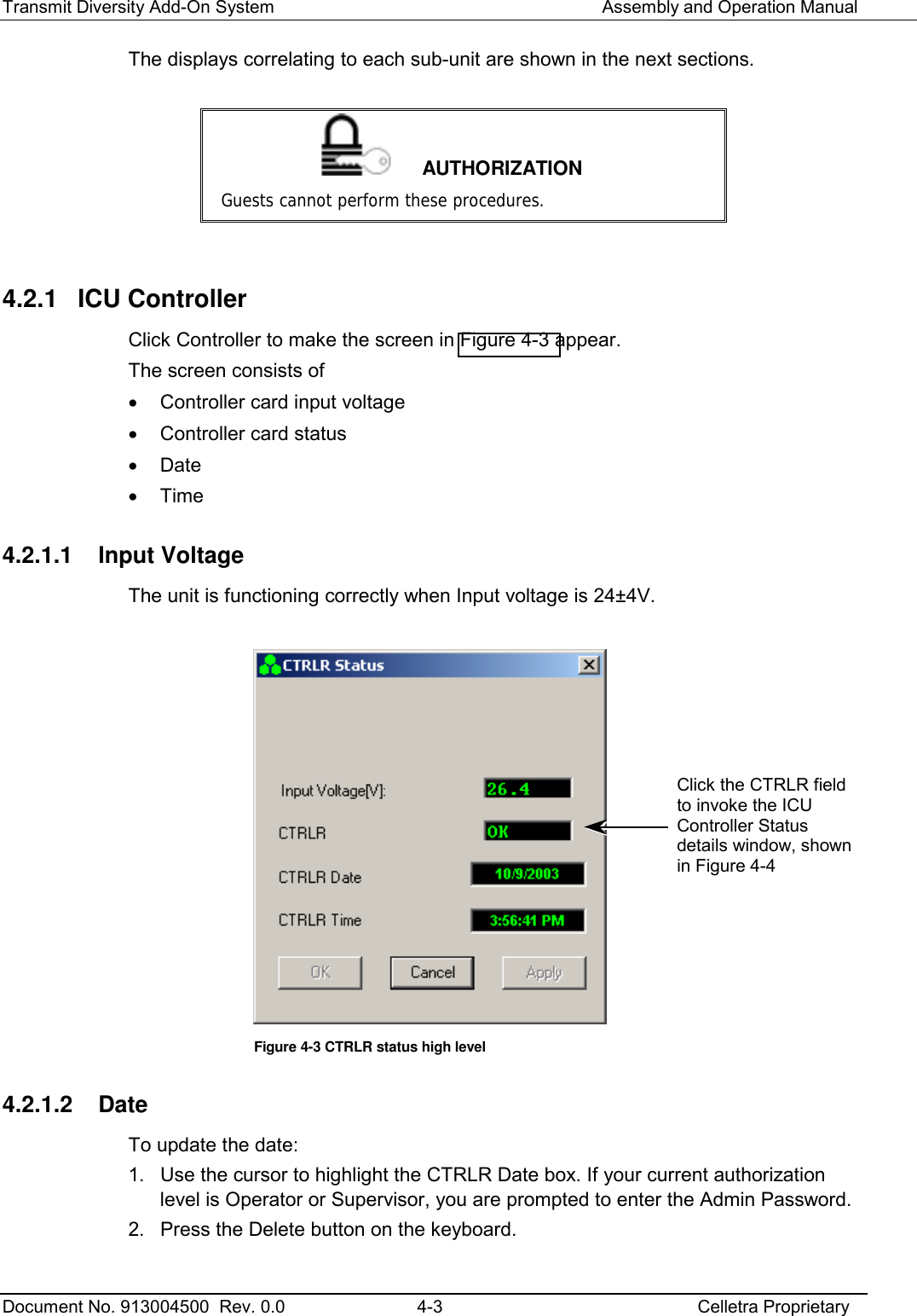
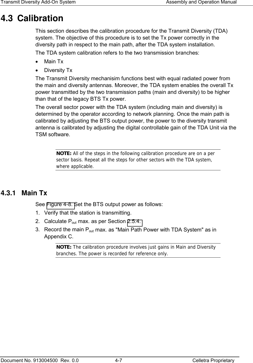
![Transmit Diversity Add-On System Assembly and Operation Manual Document No. 913004500 Rev. 0.0 4-9 Celletra Proprietary Figure 4-9 TDA System: Number, Name, and Type 4. Get the main and diversity antennas and the coax cables data from the cable shelf to the antennas. Look for the details belo: • Cable types and lengths • RF attenuations at operating frequency [dB] • Antenna types [verify that both sector antennas are isentical] 5. Measure the RF loss for the main and diversity paths according to. Main path loss = W2 + LG1+LG2 ≡ A Diversity path loss= W2+Coupler Loss (30dB) + W3 + Att loss (20dB)+ +W5+LG3 ≡ B Comments: 1. All losses (W2÷ W5, LG1÷ LG3) are positive values in dB 2. If adapter is used instead of W2 the loss is negligible 3. Coupler insertion loss is negligible 6. Calculate the TDA required gain (Downlink Gain [dB]) according to: Set Gain [dB] = B – A 7. Set the Set Gain integer value in the Ststus and Control screen rounding up (B – A). 8. Record the above Gain as " TDA Unit Downlink Gain Setting" in Appendix C.](https://usermanual.wiki/Celletra/C-ENCR-CBS021/User-Guide-440638-Page-37.png)