Celletra C-ENCR-CBS021 Cellular CellEnhancer Unit User Manual Transmit Diversity Add On System
Celletra Ltd. Cellular CellEnhancer Unit Transmit Diversity Add On System
Celletra >
manual
Cellular Transmission Solutions
Document No. 913004500 Rev. 0.0 i Celletra Proprietary
Transmit Diversity Add-On
System
Assembly and Operation Manual
October 2003
Document No. 913004500 Rev. 0.0
TDA Unit

Document No. 913004500 Rev. 0.0 ii Celletra Proprietary
Copyright
All data and information contained in or disclosed by this document is confidential and
proprietary information of Celletra Ltd and all rights therein are expressly reserved. By
accepting this material, the recipient agrees that this material and the information
contained therein is held in confidence and in trust and will not be used, copied,
reproduced in whole or in part, nor its Contents revealed in any manner to others,
without the explicit written permission of Celletra Ltd.
Changes are periodically made to the information contained in this manual. These
changes are published in the "software/hardware release notes", and will be
incorporated into new editions. All rights are reserved. No parts of this manual may be
reproduced in any form, without permission in writing from Celletra Ltd. Copyright©
2003, Celletra Ltd.
BEAMER® is a trademark of Celletra Ltd.
Celletra Ltd. reserves the right to change specifications without notice.
*All third-party trademarks are the properties of their registered owners.
Transmit Diversity Add-On System Assembly and Operation Manual
Document No. 913004500 Rev. 0.0 iii Celletra Proprietary
Preface
• This manual provides instructions for mounting, setting-up, and monitoring
Celletra’s TDA system.
Celletra’s TDA system is only for installation indoors or in an outdoor shelter.
WARNING
Do not expose the TDA equipment to open-air moisture or
rain.
Record of Changes
Change Description Initiated by Date
0 Release Erez Mutzafi October 2003
Repeater Software (TSM) Versions
This manual covers the versions of the TDA System Manager (TSM) software
version listed below. If your TSM version is not listed, check with Celletra or
your Celletra dealer if this manual still applies. If it does, add the version
number to this table.
TSM Version Date
5.0.0.106 October 2003
Transmit Diversity Add-On System Assembly and Operation Manual
Document No. 913004500 Rev. 0.0 iv Celletra Proprietary
Safety Information
This section describes the use of warnings, cautions, and notes in this manual.
It is the user’s responsibility to follow all safety instructions and regulations.
NOTE: Notes clarify issues.
CAUTION
This symbol indicates special CAUTION required in a
procedure. CAUTION signs prevent actions that may result in
equipment malfunction or damage.
WARNING
WARNING signs prevent actions that may result in harm to
personnel.
Transmit Diversity Add-On System Assembly and Operation Manual
Document No. 913004500 Rev. 0.0 v Celletra Proprietary
CAUTION
Changes or Modifications not expressly approved by Celletra
Ltd. could void the user’s authority to operate the equipment.
For customer and technical support, contact
www.celletra.com or send an E-mail to support@celletra.com
WARRANTY
The following is to inform you that Celletra Ltd. warrants its products as per
agreement.
Exclusions
The warranty (as per the agreement) shall not apply to defects resulting from:
improper or inadequate use, unauthorized modifications or misuse.
Warranty Limitations
Under no circumstances will Celletra Ltd. be liable in any way to the user or
any third party for damages, including any loss of profits, lost savings, or other
incidental or consequential damages arising out of the use of, or inability to
use, the product.
Transmit Diversity Add-On System Assembly and Operation Manual
Document No. 913004500 Rev. 0.0 vi Celletra Proprietary
System Measurement and Testing Warnings
WARNING
When testing the units in the lab or during field installation,
always practice RF radiation safety rules. It is not
recommended for service or lab personnel to work closer
than two meters from the radiating antenna surfaces when
the TDA system operates.
CAUTIONS
• Disconnect the AC or DC power to the TDA Unit before
any cable is connected or disconnected from the unit.
• Always use a DC block device connected to the
measuring equipment input or output ports (spectrum
analyzer, power meter, or RF signal source), when
measuring is performed.
• Do not connect or disconnect the coaxial connectors
while power is applied to the TDA system.
• Do not apply more than 0dBm of RF input power to
any RF port of the TDA system, or irreversible damage
may occur.
• When measuring high power outputs, always verify
that the equipment input port is capable of handling
the expected output power.
• During lab or field tests, with AC or DC voltage applied
to the TDA Unit, do not use any mobile transmitters in
a range of less than 10 meters from the unit. An
unexpectedly high RF power might appear at the
output ports, which might in turn damage the
measuring equipment connected to that port.

Transmit Diversity Add-On System Assembly and Operation Manual
Document No. 913004500 Rev. 0.0 vii Celletra Proprietary
Glossary
ABT Active Bias T
BTS Base Transceiver Station
CDMA Code Division Multiple Access
dB Decibel measurement of gain and loss
dBm Decibel measurement of power or amplitude, related
to 1mW
DL Down-link from the donor base station to the mobile
users
DLDU Down-link Diversity Units
FWD forward
HP High Power
ICU Interface and Control Unit
LPA Linear Power Amplifier
M&C Monitoring and Control
MRC Maximum Ratio Combining
MS Mobile Station (cellular phone)
mW Milliwatt
NOC Network Operating Center
PA Power Amplifier
PCS Personal Communications Services
RF Radio Frequency
Rx Receive
TD Transmit Diversity
TDA Transmit Diversity Add-on
TDR Time-Domain Reflectometer
TDU Transmit Diversity Units
TSM TDA System Manager
Tx Transmit

Transmit Diversity Add-On System Assembly and Operation Manual
Document No. 913004500 Rev. 0.0 viii Celletra Proprietary
Table of Contents
CHAPTER 1. INTRODUCTION.................................................................................................................. 1-1
1.1 About Celletra’s TDA System............................................................................................................. 1-1
1.2 TDA System Description.................................................................................................................... 1-2
1.2.1 Block Diagram..................................................................................................................... 1-2
1.2.2 General Description.............................................................................................................. 1-2
CHAPTER 2. INSTALLATION PROCEDURE........................................................................................... 2-1
2.1 Pre-installation Procedures ................................................................................................................. 2-1
2.1.1 Receiving and Inspecting the Units........................................................................................ 2-1
2.1.2 Required Tools and Test Equipment ...................................................................................... 2-2
2.2 Verify BTS Transmitted Power........................................................................................................... 2-2
2.3 Run Sweep Test................................................................................................................................. 2-2
2.4 Mount the TDA Unit.......................................................................................................................... 2-3
2.4.1 Mount the TDA Unit ............................................................................................................ 2-4
2.5 Mount the TDA System Sub-Modules................................................................................................. 2-4
2.5.1 Precautions.......................................................................................................................... 2-4
2.5.2 RF Connection..................................................................................................................... 2-5
2.5.3 Ground Connection .............................................................................................................. 2-6
2.5.4 TDA Input Power Measurement............................................................................................ 2-6
2.6 Prepare the Electrical Power Connections............................................................................................ 2-7
CHAPTER 3. TDA SYSTEM SETUP .......................................................................................................... 3-1
3.1 Install the TSM (TDA System Manager).............................................................................................. 3-1
3.1.1 Notify NOC (Network Operating Center)............................................................................... 3-1
3.1.2 Install the Software .............................................................................................................. 3-1
3.1.3 Power-on the TDA Unit........................................................................................................ 3-2
3.1.4 Connect the PC to the TDA Unit ........................................................................................... 3-2
3.2 Initial TSM Launch............................................................................................................................ 3-2
3.2.1 Authorization levels ............................................................................................................. 3-2
3.2.2 Define COMM Settings and Connection Type........................................................................ 3-5
3.3 Navigate the TDA System Setup and Configuration Windows............................................................... 3-6
3.3.1 Status and Control................................................................................................................ 3-6
3.4 Set the TDA Identification and Clock.................................................................................................. 3-8
3.4.1 TDA System Name and Number ........................................................................................... 3-8
3.4.2 TDA System Time and Date ................................................................................................. 3-9
CHAPTER 4. SYSTEM CALIBRATION..................................................................................................... 4-1
4.1 Access the System ............................................................................................................................. 4-1
4.2 Configuration .................................................................................................................................... 4-1
4.2.1 ICU Controller..................................................................................................................... 4-3
4.2.2 DLDL and Driver................................................................................................................. 4-5
4.2.3 Power Amplifier (PA) .......................................................................................................... 4-6
4.3 Calibration ........................................................................................................................................ 4-7
4.3.1 Main Tx Calibration ............................................................................................................. 4-7

Transmit Diversity Add-On System Assembly and Operation Manual
Document No. 913004500 Rev. 0.0 ix Celletra Proprietary
4.3.2 Diversity (TD) Tx Calibration ............................................................................................... 4-8
4.4 TSM Software Version..................................................................................................................... 4-10
4.5 PC Disconnect from TDA Unit ......................................................................................................... 4-10
CHAPTER 5. SERVICING AND TROUBLESHOOTING THE TDA SYSTEM.......................................... 5-1
5.1 Servicing the TDA............................................................................................................................. 5-1
5.2 Troubleshooting ................................................................................................................................5-1
5.3 Log File ............................................................................................................................................ 5-2
5.3.1 Access the Log..................................................................................................................... 5-2
5.3.2 Display the Log.................................................................................................................... 5-3
5.3.3 Store the Log ....................................................................................................................... 5-3
5.3.4 View as HTML.................................................................................................................... 5-4
APPENDIX A. DEFAULT SYSTEM LIMITS .................................................................................................. 1
APPENDIX B. CONNECTOR PINS ................................................................................................................ 2
APPENDIX C. RECORDS ............................................................................................................................... 3

Document No. 913004500 Rev. 0.0 1-1 Celletra Proprietary
Chapter 1. Introduction
1.1 About Celletra’s TDA System
Celletra Transmit Diversity (TD) technology for CDMA signals enhances the forward
link performance by improving the transmit power management, reducing blocking
rate, and increasing capacity.
The TD technology is available as an add-on to existing (legacy) base stations. In
this case, separate components are added to an existing cell site to enhance the
performance that can be achieved by the cell site alone on a per-sector basis. This
overview of the technology will provide some insights regarding how the TD solution
can be applied to a cell site to enhance capacity performance at the site.
Add-on Transmit Diversity (TDA) provides for redundant replicas of transmitted
signals (from the base station) by transmitting the same information over two or
more antennas, providing independently faded channels between the BTS transmit
and mobile receive antennas. In order to maintain the total transmitted power (or
EIRP), each of the two base station transmit antennas in a TDA system has to
transmit a minimum of 50% of the power from a conventional one transmit antenna
system. Alternatively, higher power may be transmitted in addition to diversity gain
by the two antennas (main and diversity). In this case, the cell footprint in the Down-
link will increase, or (after down-tilting the antennas) the same coverage with higher
capacity is obtained.
The TDA system reduces the per-link-power required for the mobile station (phone).
Moreover, reducing the blocking-rate and access-failures improves the cell forward
(FWD) link capacity. As a result, in FWD link limited sites, sector erlangs increase.
The TD process is carried out only at the base station; no modifications are required
at the mobile handset. This gives TDA a clear advantage over other transmit
diversity schemes such as OTD and STS which require new chipsets to be included
in the mobile handset.
Transmit Diversity Add-On System Assembly and Operation Manual
Document No. 913004500 Rev. 0.0 1-2 Celletra Proprietary
1.2 TDA System Description
1.2.1 Block Diagram
Figure 1-1 describes the TDA system.
TDA Unit
BTS (CDMA - Cellular)
Transmit
Diversity
Unit
TX
Diversity
Antenna
Tx1/Rx1
Outdoors
Shelter
FRM
Coupler
DPM
Rx2 Rx1 Tx1
CDMA, 1 carrier
TDU
Attenuator
-48VDC
Major
Alarm
TB - No connector
Cables
Panel
Ground
LPA
CB - TB
TX/RX
Main
Antenna
Antennas
Installation
(Top-view)
Tower
Rx2
Diversity
Port
Figure
1-1 TDA block diagram
1.2.2 General Description
The Celletra TDA system consists of the TDA Unit and Coupler:
The TDA Unit interfaces transparently to the BTS at RF low-power levels. The TDA
Unit generates the Transmit Diversity (TD) signals and power-amplifies the TD
signals to be transmitted through the Tx-Diversity antenna.
Document No. 913004500 Rev. 0.0 2-1 Celletra Proprietary
Chapter 2. Installation Procedure
NOTE: Installing the TDA system requires site parameters, including
the channel number in use, gain settings, and required sector power. If
necessary, consult your network administrator for more information.
2.1 Pre-installation Procedures
2.1.1 Receiving and Inspecting the Units
CAUTION
Verify that the shipment is complete and undamaged. If the
boxes appear damaged, do not open the shipment.
NOTE: It is recommended to save the original shipping carton and
packing materials for any future transportation of the TDA System.
Follow this procedure prior to installation:
1. Unpack the shipment boxes.
2. Verify the contents of the boxes against the packing inventory lists.
3. Inspect the TDA system for possible damage.
The following items are required for the installation. They are supplied separately.
• Documentation: This Assembly and Operation Manual.
• Software: TSM (TDA System Manager) CD, ready for installation. This
software is for setup and tuning of the system during installation.
Instructions for using TSM are located in Chapter 3. & Error! Reference
source not found.

Transmit Diversity Add-On System Assembly and Operation Manual
Document No. 913004500 Rev. 0.0 2-2 Celletra Proprietary
2.1.2 Required Tools and Test Equipment
Table 2-3: Tools and test equipment
Equipment Use
Digital Voltmeter Fluke 77 or
equivalent
Measure voltage and polarity for the installation process
Pilot Scanner Measure Donor pilot signal levels
Frequency domain Reflectometer Check Insertion loss and VSWR for system RF Cables
Network Analyzer (optional) Check Insertion loss and VSWR for system RF Cables
PCS Band Signal Generator Check diversity path gain
Spectrum Analyzer Check TDA Unit Output Power
30dB 100W attenuator (PCS Band) Protect RF Test equipment from overpowered signals
Standard calibrated jumper cables Test equipment usage
Laptop PC equipped with Windows 95,
98, NT, or Windows 2000 with Service
Pack 3.
Configure, control, and monitor the TDA using the TSM
software through the RS-232 communication port
2.2 Verify BTS Transmitted Power
Verify that the BTS is running normally, transmitting a certain output power.
Find a calibrated Tx test point to measure the BTS output power (Tx, Down-link).
Measure the BTS power and record it including the date and time. If such a
calibrated test-point does not exist, refer to 2.5.4.
The Traffic load should be taken into account while setting up the TDA
system. Allow a suitable power margin for possible load rise.
In any case, refer to the measured pilot power as the sector reference level. The
pilot power is usually fixed. Add 7.5dB to this level to estimate the maximal Tx
power of the sector.
Record the above main Pout max. as "Main Path Power Before TDA System" in
Appendix C.
2.3 Run Sweep Test
Before installing the cables in the system, run a sweep test of all RF cables and
record the cable loss (see Table 2-4 for RF cable list). Perform the sweep test
using a Time-Domain Reflectometer or a Network Analyzer.
Record these parameters for each RF cable:
• Insertion loss of the cable
• VSWR
• Return loss
Transmit Diversity Add-On System Assembly and Operation Manual
Document No. 913004500 Rev. 0.0 2-3 Celletra Proprietary
If you detect a fault in any of the cables, repair it and re-check until all the cables
are in order.
NOTE: Record the information for reference during the setup
procedure in Appendix C.
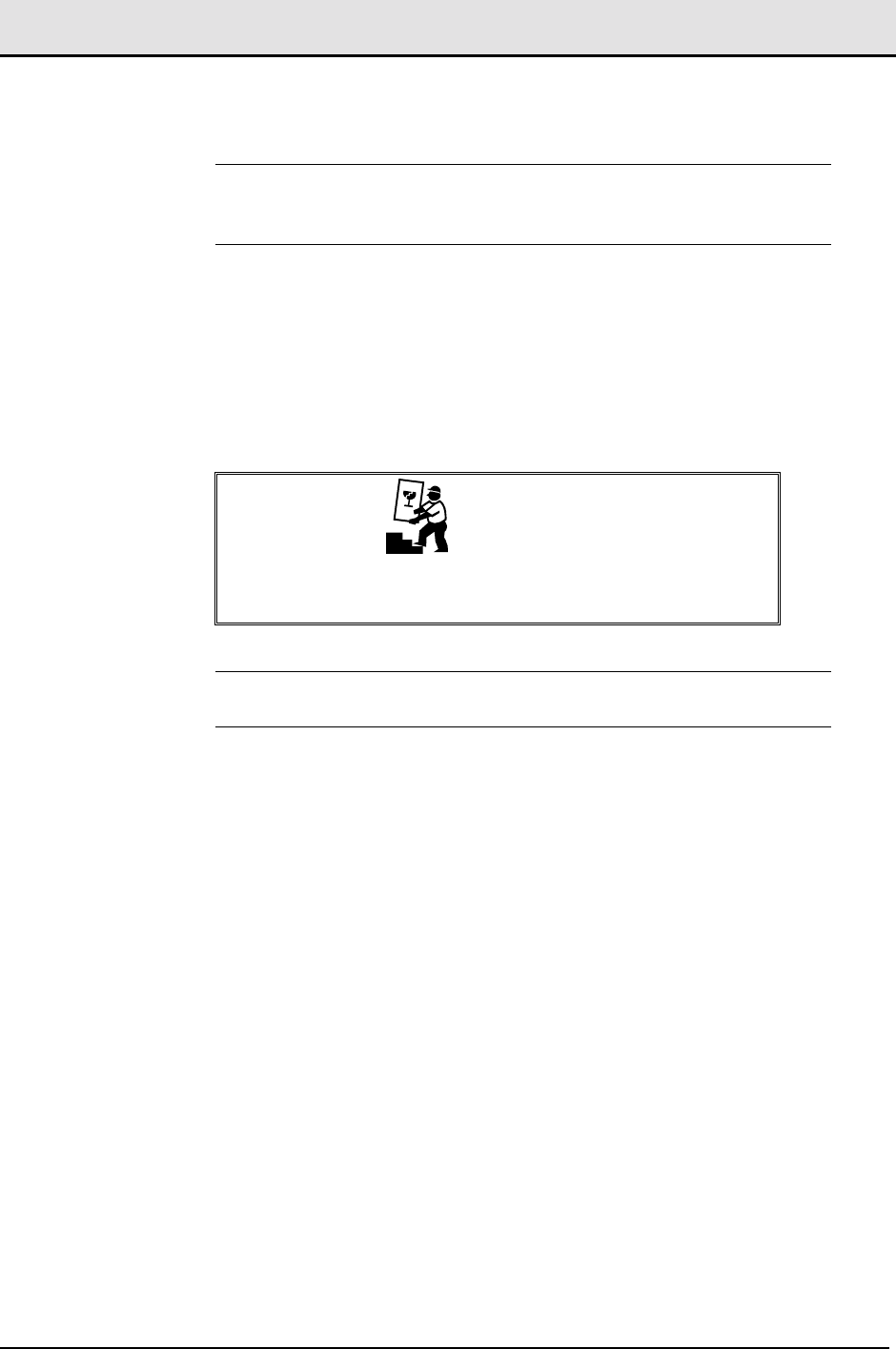
Table 2-4: RF cables sweep test
Cable # Cable Description Insertion
Loss Return
Loss Remarks
From To
W2 FRM Tx1/Rx1 Coupler
W3 Coupler Attenuator
W5 TDA Unit Cable Panel DIV
LG1 Coupler Cable Panel Main Legacy
Cable
LG2 Cable Panel Main Tx/Rx Main Antenna Legacy
Cable
LG3 Cable Panel DIV Tx DIV Antenna Legacy
Cable
2.4 Mount the TDA Unit
The TDA Unit should be installed preferably near the FRM output RF port.
CAUTION
The TDA Unit is a complex and accurate electrical apparatus
and should be treated accordingly.
Use extra caution when installing the unit in the rack.
WARNING
The TDA Unit does not have an ON/OFF switch. Therefore,
do not connect the DC supply to this unit until the end of the
installation.
Transmit Diversity Add-On System Assembly and Operation Manual
Document No. 913004500 Rev. 0.0 2-4 Celletra Proprietary
WARNING
RECAP THE POWER AND COMMUNICATION CONNECTORS
UNTIL THE TDA SYSTEM IS READY TO BE SET UP. DO NOT
CONNECT POWER YET.
2.4.1 Mount the TDA Unit
1. Place the TDA Unit in the rack.
2. Tighten the four screws at the Unit sides.
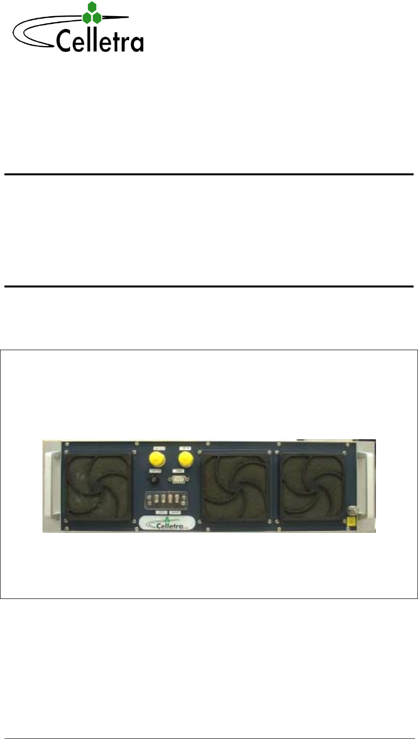
Figure
2-1 TDA Unit front panel
2.5 Mount the TDA System Sub-Modules
2.5.1 Precautions
CAUTIONS
• Always shut down the AC or DC supply to the TDA
Unit before handling replacing or removing the Unit
from the rack.
• While you may disassemble the TDA Unit from the
rack as required, under no circumstances should you
open the unit.
Transmit Diversity Add-On System Assembly and Operation Manual
Document No. 913004500 Rev. 0.0 2-5 Celletra Proprietary
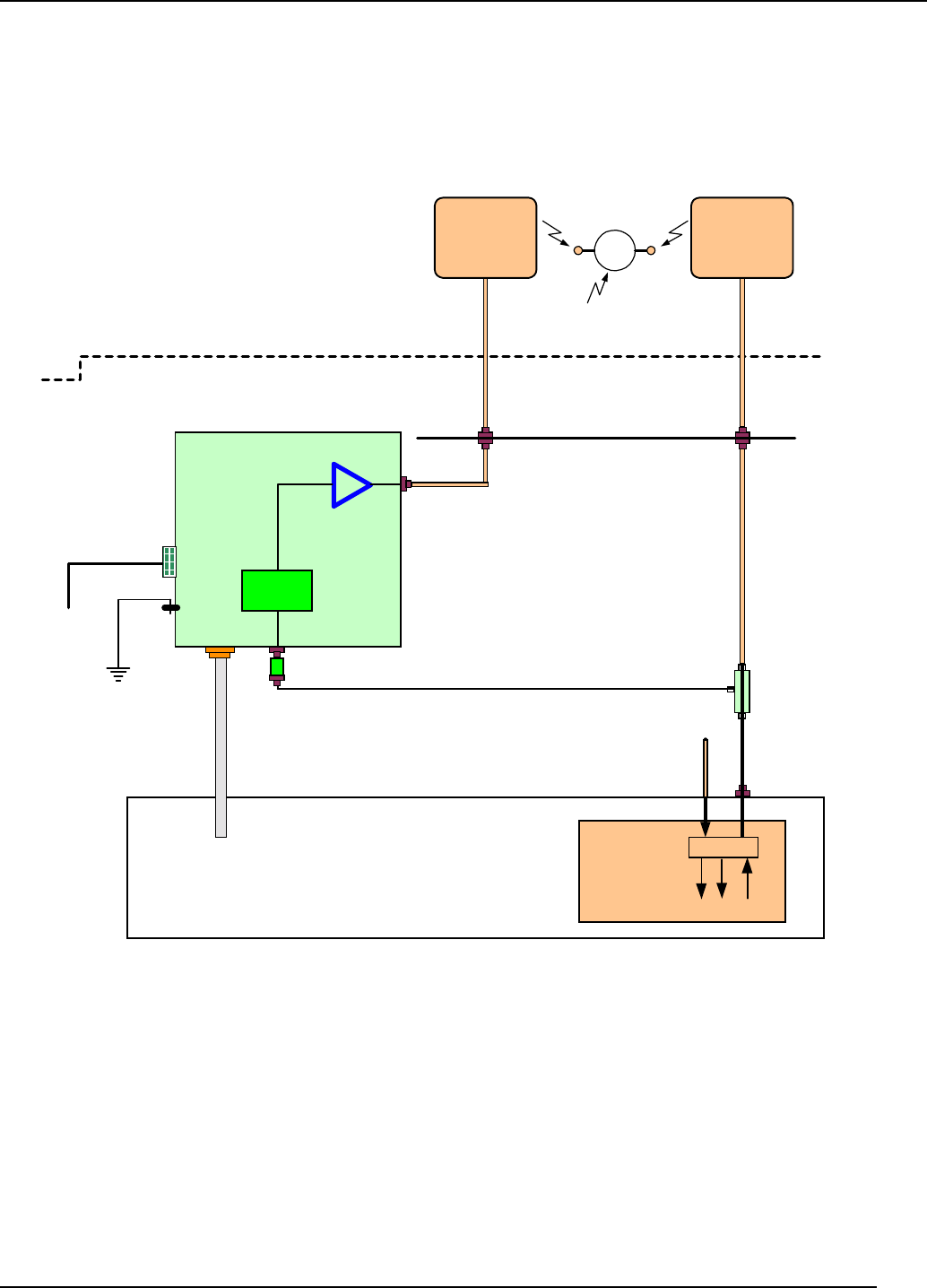
2.5.2 RF Connection
TDA Unit
BTS (CDMA - Cellular)
Transmit
Diversity
Unit
TX
Diversity
Antenna
Tx1/Rx1
Outdoors
Shelter
FRM
Coupler
DPM
Rx2 Rx1 Tx1
CDMA, 1 carrier
TDU
Attenuator
-48VDC
Major
Alarm
N-M
N-M
N-M
N-M
N-M
TB - No connector
W1
W2
W3
7-F
7-M
W5
W6
N-M or 7-M
7-F
7-M
Cables
Panel
N-M & N-F
Ground
LPA
CB - TB
W7
TX/RX
Main
Antenna
Antennas
Installation
(Top-view)
Tower
Rx2
Diversity
Port
Figure
2-2 TDA cables connection
The main Tx path must be open when installing the sampling coupler. Therefore:
1. Contact the Network Operating Center (NOC) to get permission to wilt the
station.
WARNING
Disconnecting the main Tx path without wilting the station
may cause damage to the station or to personnel.
Transmit Diversity Add-On System Assembly and Operation Manual
Document No. 913004500 Rev. 0.0 2-6 Celletra Proprietary
2. Wilt the sector.
3. Open the main Tx path so that the sampling coupler can be installed.
4. Connect the coupler inline at the DPM Tx/Rx antenna port, using a male-male
N-type adapter or a short cable (W2).
5. Reconnect the legacy cable to the other (open) dircet side of the coupler. Use
connector adapter if required.
6. Connect W3 and the Attenuator between RF IN port on the TDA Unit and the
Coupled Port of the coupler.
7. Connect W5 between the Tx Div antenna port (RF OUT) on the TDA Unit and
the bulkhead.
CAUTION
Do not provide DC power to the TDA Unit yet.
2.5.3 Ground Connection
Make sure to connect the TDA Unit to the frame's chassis or the ground buss bar
in the shortest way possible.
Do not chain the ground connection between units.
CAUTION
If you are using a 3-phase outlet system, do not connect any
Ground to the Neutral.
2.5.4 TDA Input Power Measurement
1. Bloom the station. Verify that the station transmits a pilot signal only.
2. Don’t turn the TDA Unit power on.
3. Disconnect the attenuator from the TDA Unit.
4. Measure the pilot power from the attenuator. Record this level. Make sure
that the attenuator is connected to W3.
5. Do not allow the power to exceed 0dBm.
6. Reconnect the attenuator to the TDA Unit.
7. Calculate the BTS output max. power.
Pout max. = Ppilot + 7.5dB + Attloss + W3loss + Couplerloss
where
Transmit Diversity Add-On System Assembly and Operation Manual
Document No. 913004500 Rev. 0.0 2-7 Celletra Proprietary
Attloss = 20dB
W3loss = W3 Insertion loss, as measured in Table 2-4 [dB]
Couplerloss = 30dB
Pout max. = Ppilot + 7.5dB + 20dB + W3loss + 30dB
Pout max. = _______dBm
Record the above main Pout max. as "Main Path Power After TDA System" in
Appendix C.
2.6 Prepare the Electrical Power Connections
CAUTION
Power to the units must be supplied according to the safety
standards in the corresponding country (grounded outlets,
circuit breaker, conduits, etc.). Check the power cable before
connecting it to the units.
NOTE: Fuse is located on the TDA Unit front panel. Ensure the fuse is
pushed in.
1. Supply power to the TDA Unit.
2. Verify that the unit is working properly by connecting directly with a PC as
explained in the next Chapter.The three fans at the front panel are working
only in case of excessive internal temprature. Thus, in an airconditioned site
they may stay idle for long time priods.

Document No. 913004500 Rev. 0.0 3-1 Celletra Proprietary
Chapter 3. TDA System Setup
The general term for the software that manages Celletra's system is the Celletra
System Manager. The software can process several types of systems (Repeaters,
Cell-On-Wheels upgrade, etc.). The software for the TDA system type is called the
TSM (TDA System Manager).
TSM features:
• TDA System monitoring
• TDA System control: setting and tuning
• Local (direct) connection to the TDA System
Follow the steps in this chapter to install and set up the TSM software for initial use.
Chapter 4. explains how to use TSM for maintenance and calibration procedures.
3.1 Install the TSM (TDA System Manager)
The PCs on which the software will be installed must meet these minimum
requirements:
• PentiumTM-based
• Available serial port
• 4Mb free RAM or more
• Windows* 95, 98, or NT*, or Windows 2000 with Service Pack 3.
3.1.1 Notify NOC (Network Operating Center)
Notify NOC of the new System installation.
3.1.2 Install the Software
1. Insert the CD-ROM provided by Celletra in the CD drive and run Setup, located
in the Package folder.
2. Follow the instructions. The installation software installs the program bsm.exe in
the Program Files folder on your C: drive.
3. Create a shortcut on your desktop to bsm.exe. The shortcut icon is Celletra's
triple hexagon symbol.
4. Copy the bsmutils folder from the CD-ROM to the root of your C: drive (C:\).
Transmit Diversity Add-On System Assembly and Operation Manual
Document No. 913004500 Rev. 0.0 3-2 Celletra Proprietary
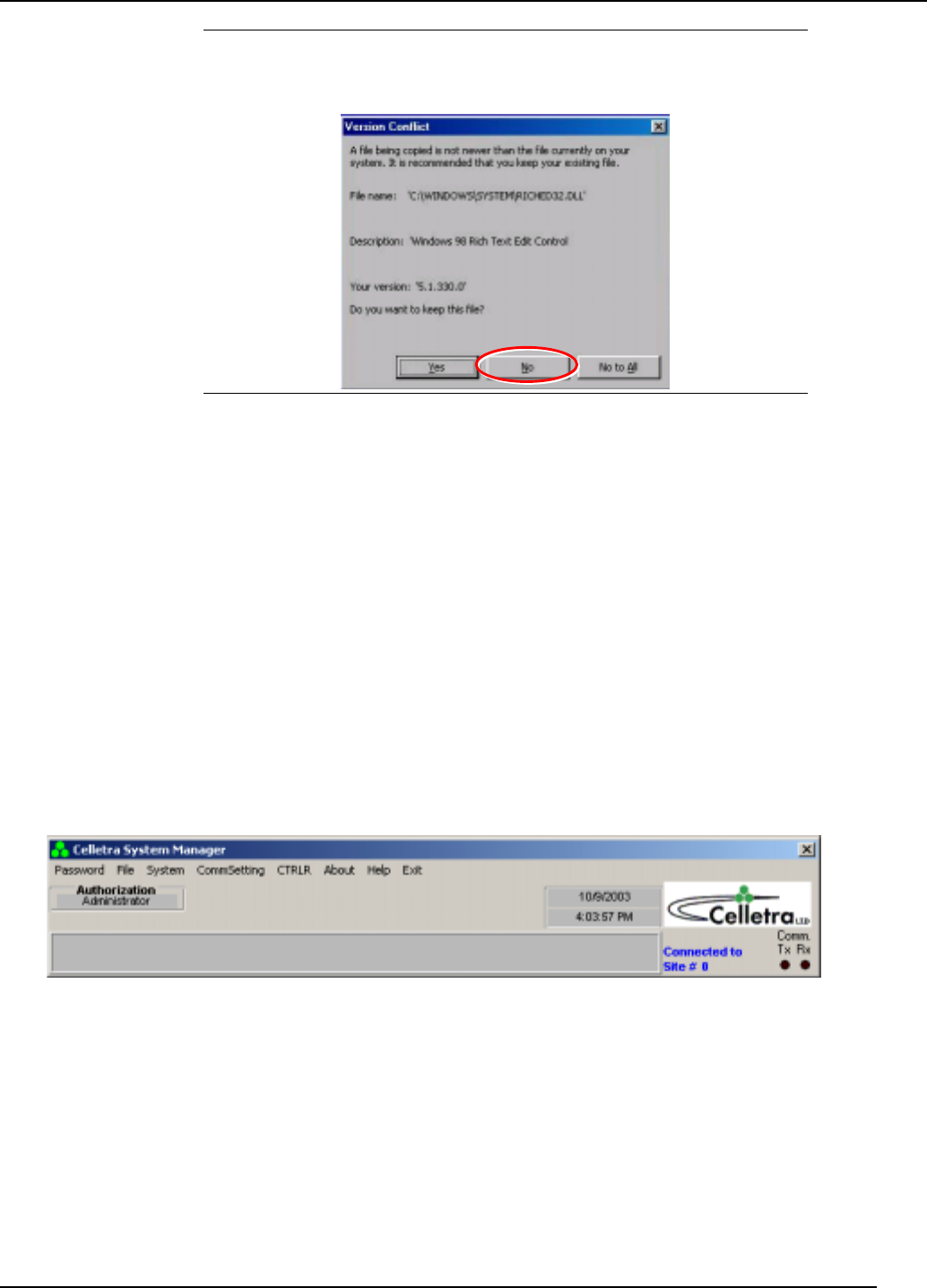
NOTE: When installing on Windows 98, you may be asked whether to
keep an existing file called Richtx32.ocx or replace it with a new version.
Select No.
3.1.3 Power-on the TDA Unit
If the TDA Unit is not turned on, power-on the TDA System by connecting the power
cord to the TDA unit, and lidt-up the circuit breaker.
3.1.4 Connect the PC to the TDA Unit
You may setup and monitor the TDA System through local connection, using the
communication cable supplied by Celletra, connected to the C&M –Type connector.
3.2 Initial TSM Launch
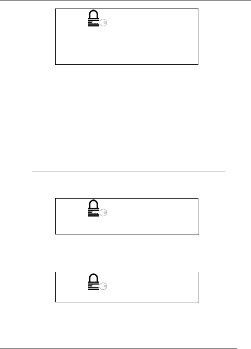
Double-click the TSM icon on your desktop. The TSM menu bar appears.
Figure
3-1 TSM menu bar
If your system is connected to comm port 1, the system block diagram also appears.
Section 4.2 describes fully how to use this block diagram to maintain your system
parameters.
3.2.1 Authorization levels
Transmit Diversity Add-On System Assembly and Operation Manual
Document No. 913004500 Rev. 0.0 3-3 Celletra Proprietary
AUTHORIZATION
First time access to the system does not require you to enter
a password. You will automatically be granted the
authorization of an Administrator.
NOTE: This is the right time to define the passwords for all
authorization levels.
After the first time you use TSM, you will access the software with one of these
authorization levels.
Guest No password is required. Shows most definitions and some
monitored parameter values. No editing is permitted.
Operator Shows all definitions and monitored parameter values.
Provides edit capability to Modem Number field (TSM menu,
System, Modem Definitions) only.
Supervisor Provides access to all configuration and editing options except
for password, date, and time changes.
Administrator Provides access to all configuration and editing options
including password changes.
Access the system at the appropriate level by entering the corresponding password.
AUTHORIZATION
This symbol alerts you to the authorization level required for
the different procedures described below.
3.2.1.1 Define Passwords
AUTHORIZATION
Administrators can perform this procedure.
The Guest authorization level does not require password definition.
You can define a single password for each of the other authorization levels.
The passwords you set here apply across the whole TDA System. Define the
passwords as follows:
Transmit Diversity Add-On System Assembly and Operation Manual
Document No. 913004500 Rev. 0.0 3-4 Celletra Proprietary
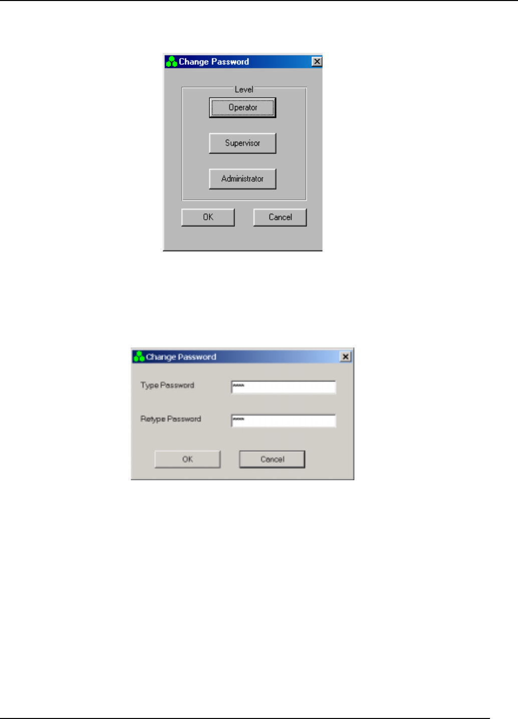
1. From the Password menu, choose Change. The following window appears.
Figure
3-2 Authorization levels
2. Click an authorization level.
3. Enter a password by typing it twice, then click OK:
Figure
3-3 Set password
4. Repeat for the other two authorization levels.
5. Click OK.
3.2.1.2 Access the System
After the initial entry to TSM, whenever you click the desktop icon you will enter
TSM with guest authorization. To change from the Guest authorization level:
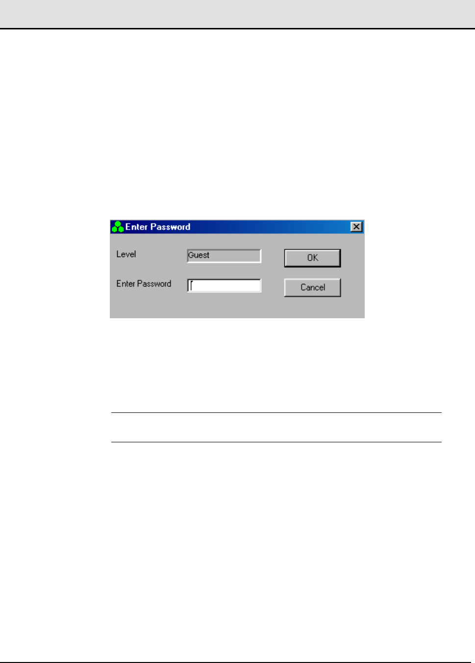
1. From the Password menu, select Enter Password. The following dialog appears
showing the current authorization level.
Transmit Diversity Add-On System Assembly and Operation Manual
Document No. 913004500 Rev. 0.0 3-5 Celletra Proprietary
Figure
3-4 Password entry
2. Enter the Password corresponding to the authorization level you require.
3. Click OK.
NOTE: All authorization levels revert to Guest level after five minutes of
inactivity.
To change from a higher authorization level to Guest level, select Low Level from
the Password menu.
3.2.2 Define COMM Settings and Connection Type
Connect to the TDA System as follows:
1. Connect the supplied RS-232 cable between the serial port on the PC and the
RS-232 port on the TDA Unit.
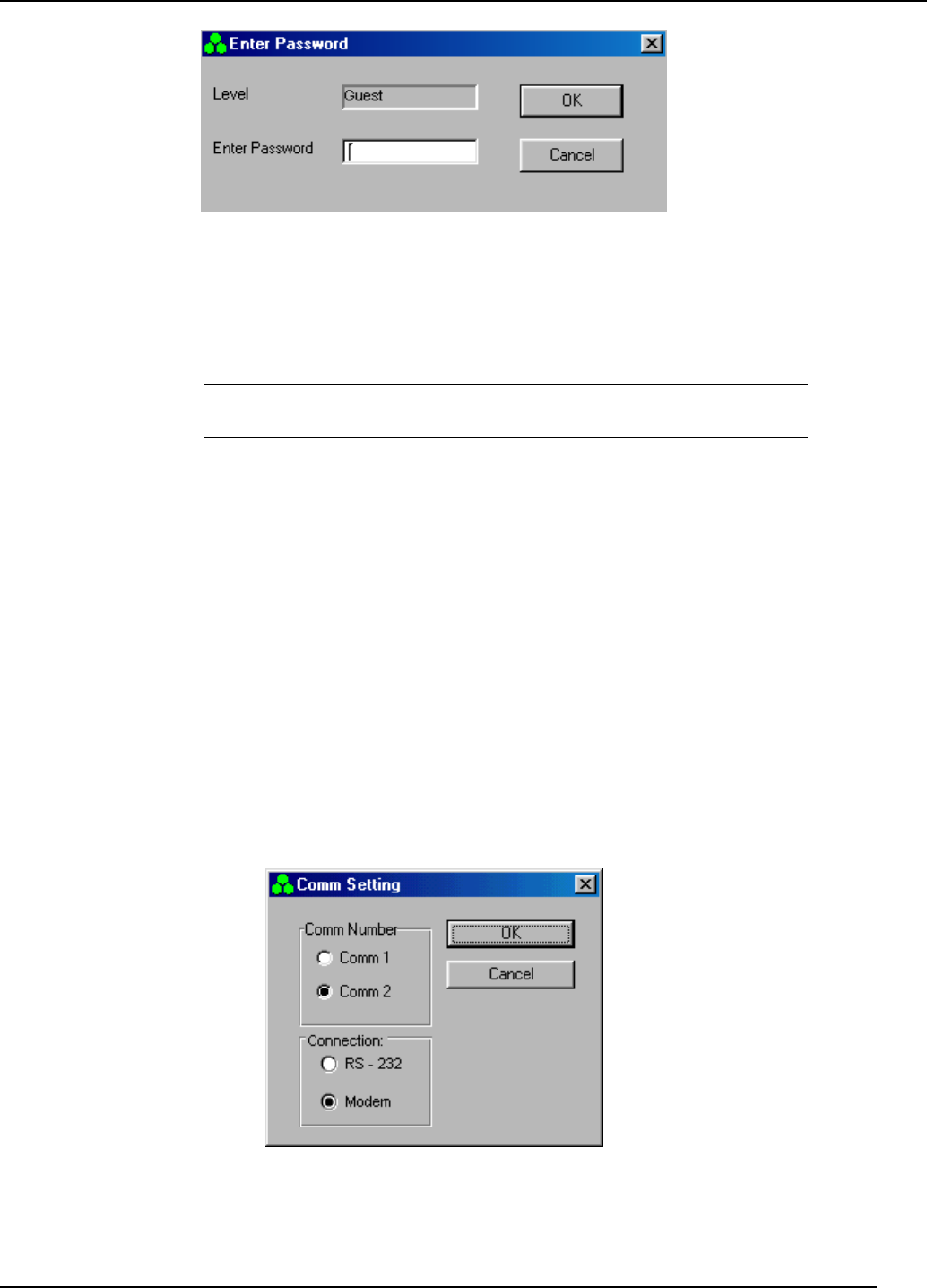
2. Click the CommSetting menu. The Comm Setting dialog appears, as shown in
Figure 3-5. Comm’s appears in that screen are according to the Comm ports
avaliable in your computer.
Figure
3-5 Comm setting dialog

Transmit Diversity Add-On System Assembly and Operation Manual
Document No. 913004500 Rev. 0.0 3-6 Celletra Proprietary
3. Under Comm Number, click the radiobutton corresponding to your PC modem
port.
4. Under Connection, click the RS-232. Modem option is not is use.
5. Click OK.
3.3 Navigate the TDA System Setup and Configuration
Windows
All TDA System setup and configuration functions are implemented from a single
menu option. To access the TDA System setup, click the System menu. The
following tabs appear.
Configuration
tab
For monitoring. This dialog shows a block diagram of the
TDA sysem, where each unit in the block diagram (PA,
Driver,…) provides access to corresponding monitoring
options. Section 4.2 fully explains this block diagram and the
data it displays.
Status and
Control tab
For setup. Contains site information, gains, cable loss
definitions, and power monitoring. See Section 3.3.1.
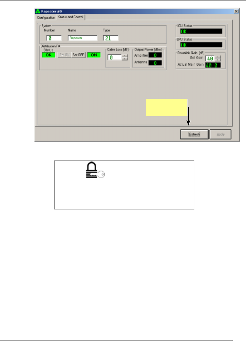
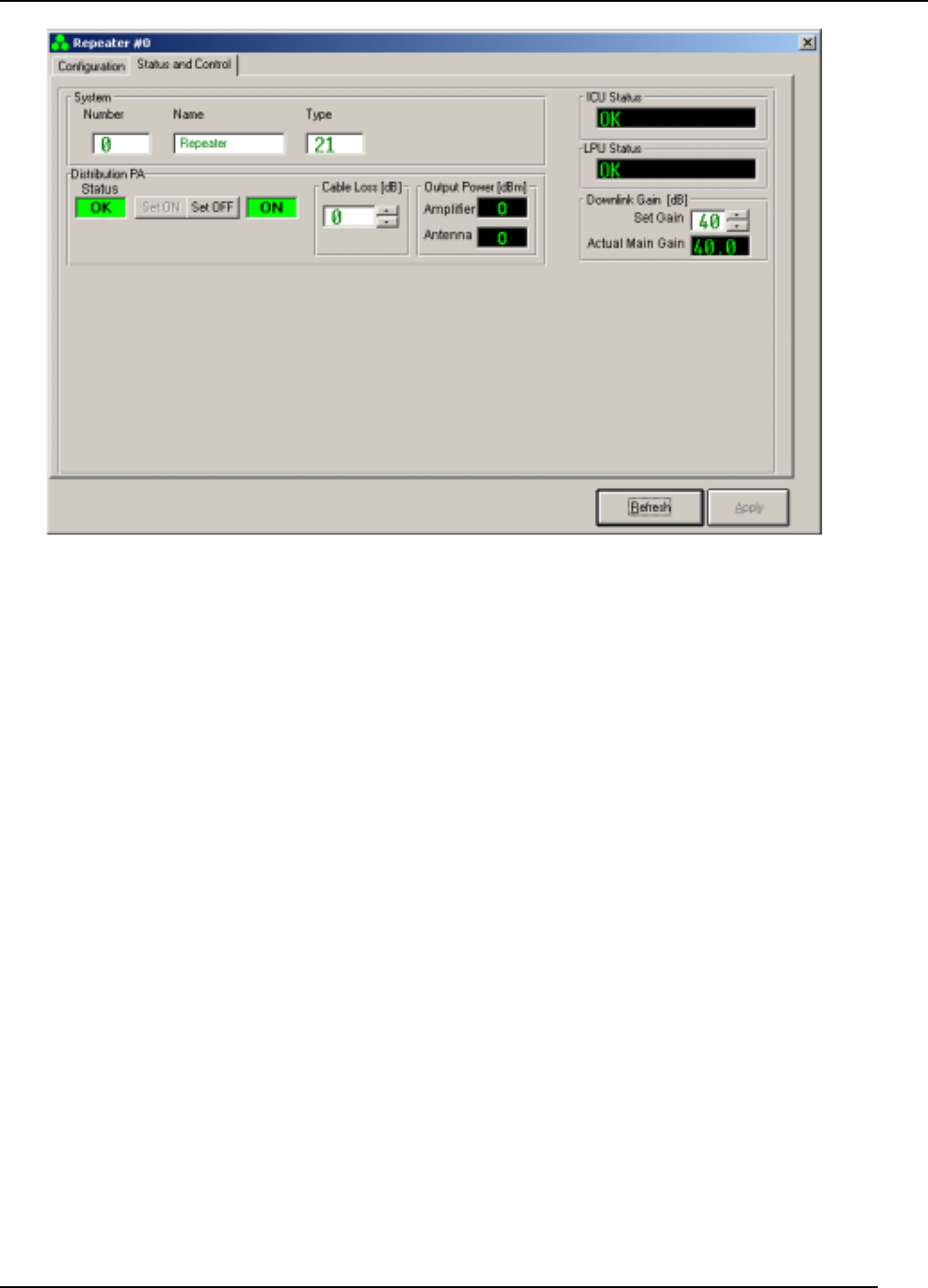
3.3.1 Status and Control
Figure 3-6 shows the dialog that appears when you click the Status and Control tab.
The System Type for the TDA system is 21.
With this tab you can change setup parameters such as
• Site Information
• Cable loss
• PA status (Distribution PA)
• PA ON/OFF
• PA output power (‘Output Power [dBm] Amlifier’)
• Output power to antenna (‘Output Power [dBm] Antenna’)
• Downlink Gain [dB]
• Actual Main Gain (monitoring)
• ICU status
• LPU ststus
Transmit Diversity Add-On System Assembly and Operation Manual
Document No. 913004500 Rev. 0.0 3-7 Celletra Proprietary
Figure
3-6 Status and Control screen
AUTHORIZATION
As discussed in Section 3.2.1, Guest and Operator levels
users are only authorized to
monitor
parameters.
Supervisor and Administrator level users are authorized to
monitor and change
parameters.
NOTE: Fields with white backgrounds can be modified. Other fields (with
black and gray backgrounds) are only for display.
To make changes to displayed parameters:
1. Click the Stop Refresh button so that the data ceases updating on the screen.
2. Make your modifications.
3. Click Apply to save your changes, or Refresh to cancel. You may be asked to
confirm your changes.
4. Wait for the changes to take effect.
5. Click X in the top right corner to close the dialog.
Stop/Start
Refresh button
Transmit Diversity Add-On System Assembly and Operation Manual
Document No. 913004500 Rev. 0.0 3-8 Celletra Proprietary
3.4 Set the TDA Identification and Clock
When status messages are sent by the TDA System to the TSM, the specific TDA
System sending the information is identified according to the following parameters,
explained below:
• TDA System number
• Site name
• Time stamp set by real-time clock settings
• Contact information (or call-back number)
3.4.1 TDA System Name and Number
AUTHORIZATION
Administrators and Supervisors can perform this procedure.
The TDA System identification details are for your record-keeping. Change them in
keeping with your company policy.
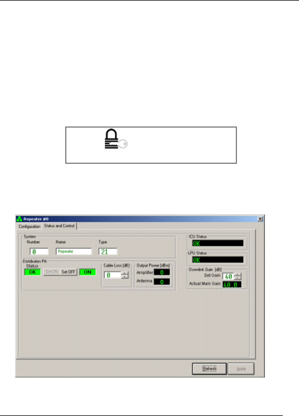
1. From the TSM System window, choose the Status and Control tab.
Figure
3-7 TDA System: Number, Name, and Type
Transmit Diversity Add-On System Assembly and Operation Manual
Document No. 913004500 Rev. 0.0 3-9 Celletra Proprietary
2. Type a TDA System number in the range 1 through 999.
3. Type a TDA System name (alphanumeric) using a maximum of 20 characters.
(You must enter both a name and a number.)
4. The system type should be 21 for the TDA System.
5. Click the Start Refresh button.
3.4.2 TDA System Time and Date
AUTHORIZATION
Administrators can perform this procedure.
NOTE: This procedure sets the TDA System date and time to the
corresponding values on the PC. To ensure that the generated logs are
accurate, check that the PC date and time are correct.
To set the time and date for the TDA System:
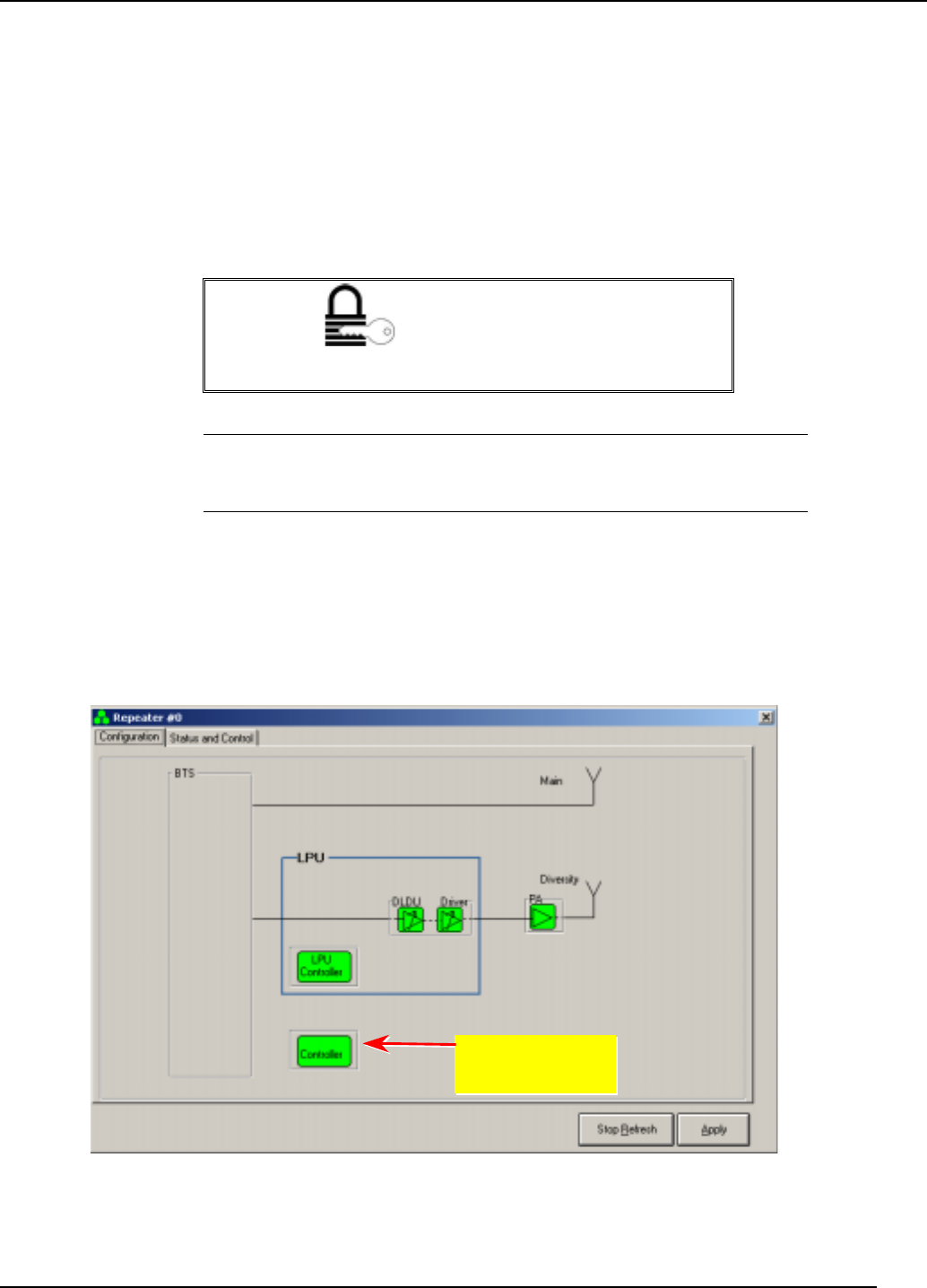
1. Select the Configuration tab.
2. Click the ICU Controller button as indicated below. The CTRLR Status dialog
shown in Figure 3-9 appears showing the status of the ICU.
Figure
3-8 Configuration screen
Click the TDA
Controller button
Transmit Diversity Add-On System Assembly and Operation Manual
Document No. 913004500 Rev. 0.0 3-10 Celletra Proprietary
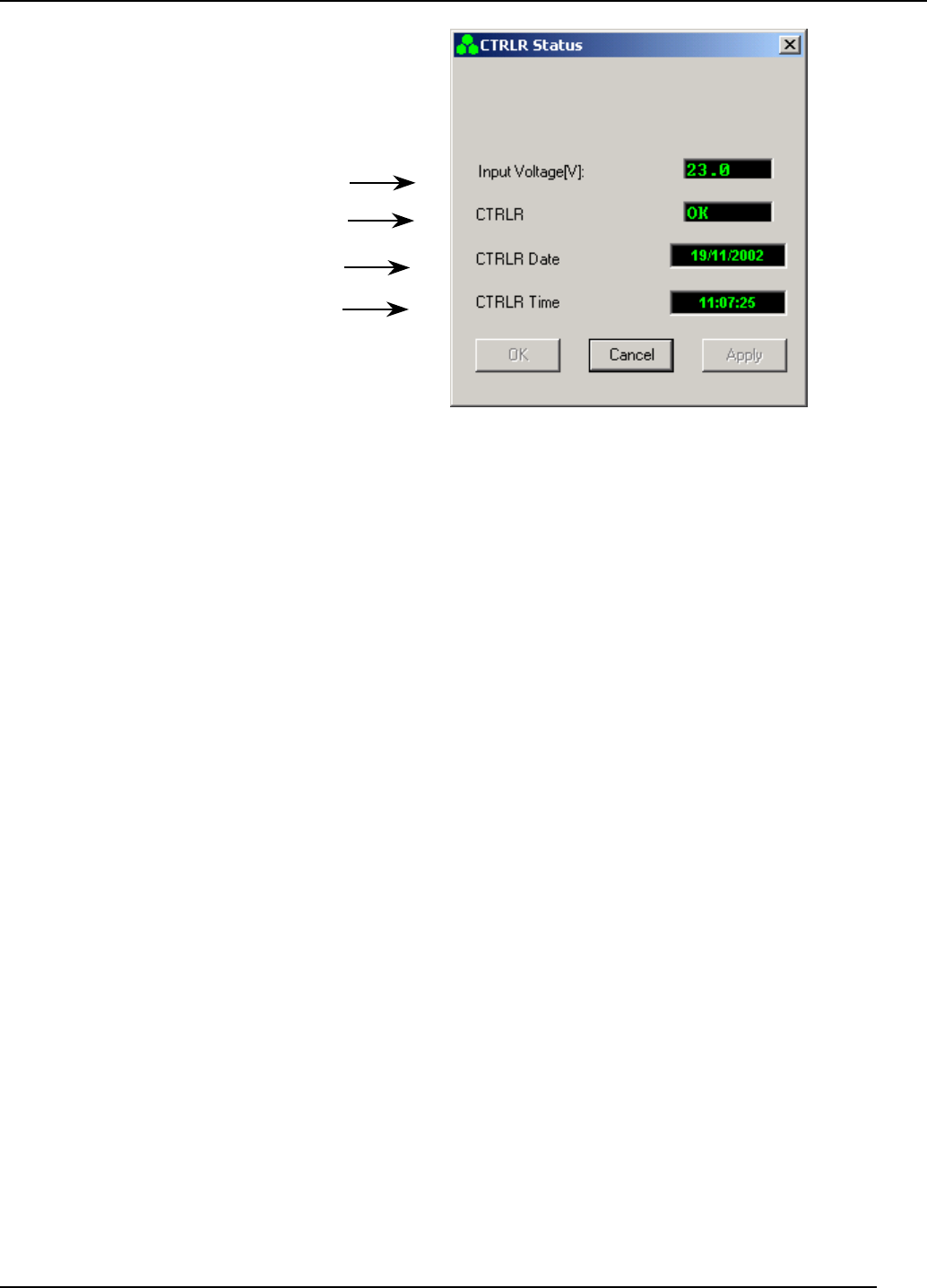
Figure
3-9 CTRLR Status high level
3. Update the date:
a. Use the cursor to highlight the CTRLR Date box. If your current authorization
level is Operator or Supervisor, you are prompted to enter the Admin
Password.
b. Press the Delete button on the keyboard.
c. Click Apply twice. The Date updates automatically according to the date on
your PC.
4. Update the time:
a. Use the cursor to highlight the CTRLR Time box. If your current
authorization level is Operator or Supervisor, you are prompted to enter the
Admin Password.
b. Press the Delete button on the keyboard.
c. Click Apply twice. The time updates automatically according to the time on
your PC.
5. Click OK.
Voltage supply to
controller card
Controller status
Controller date
Controller time
Document No. 913004500 Rev. 0.0 4-1 Celletra Proprietary
Chapter 4. System Calibration
This chapter explains how to use the TSM software to calibratein and maintain the
TDA System.
4.1 Access the System
When you click the desktop icon, you enter TSM with guest authorization. To
change from the Guest authorization level:
1. From the Password menu, select Enter Password. The following dialog appears
showing the current authorization level.
Figure
4-1 Password entry
2. Enter the Password corresponding to the authorization level you require.
3. Click OK.
NOTE: All authorization levels revert to Guest level after five minutes of
inactivity.
To change from a higher authorization level to Guest level, select Low Level from
the Password menu.
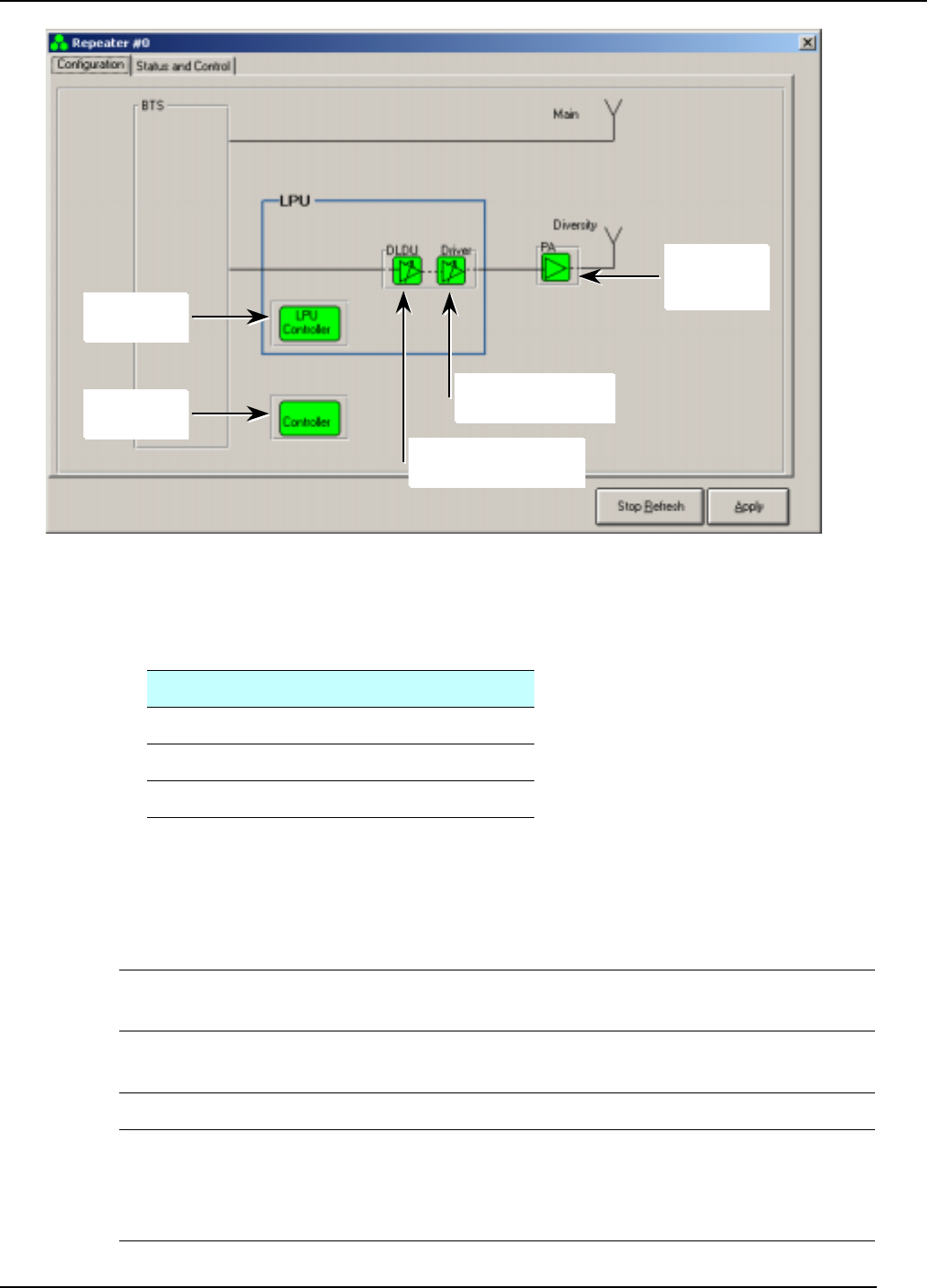
4.2 Configuration
The Configuration tab shows schematically the TDA configuration for the single
sector. It enables monitoring of all the sub-units in the system so that the
experienced user can manually change parameters that have been set up
automatically for each of the sub-units.
Figure 4-2 shows the TD and Main paths with Celletra's system.
To invoke the Configuration block diagram, select the Configuration tab.
Transmit Diversity Add-On System Assembly and Operation Manual
Document No. 913004500 Rev. 0.0 4-2 Celletra Proprietary
Figure
4-2 Configuration screen
Units in the block diagram are colored as follows:
Color Indication
Green Correct functioning
Yellow Minor misfunction
Red Failure
Using any authorization level other than Guest, click each sub-unit to view the
corresponding data. The sub-units, from left to right:
LPU
Controller
Monitors the LPU controller status , Temperature and LPU Alarms.
DLDU and
Driver
Down-link diversity unit and Driver monitor and Control.
PA LPA ststus and Control parameter. Set PA ON or OFF.
TDA Unit
Controller
Updates date and time, and monitors controller status and input
voltage. Accesses additional dialog showing TDA Unit Controller
Status parameters from which the Controller Parameters dialog is
invoked.
TDA Unit
Controller
DLDU (Down Link
Diversit
y
Unit
Driver
Power
Amplifier
LPU
Controller
Transmit Diversity Add-On System Assembly and Operation Manual
Document No. 913004500 Rev. 0.0 4-3 Celletra Proprietary
The displays correlating to each sub-unit are shown in the next sections.
AUTHORIZATION
Guests cannot perform these procedures.
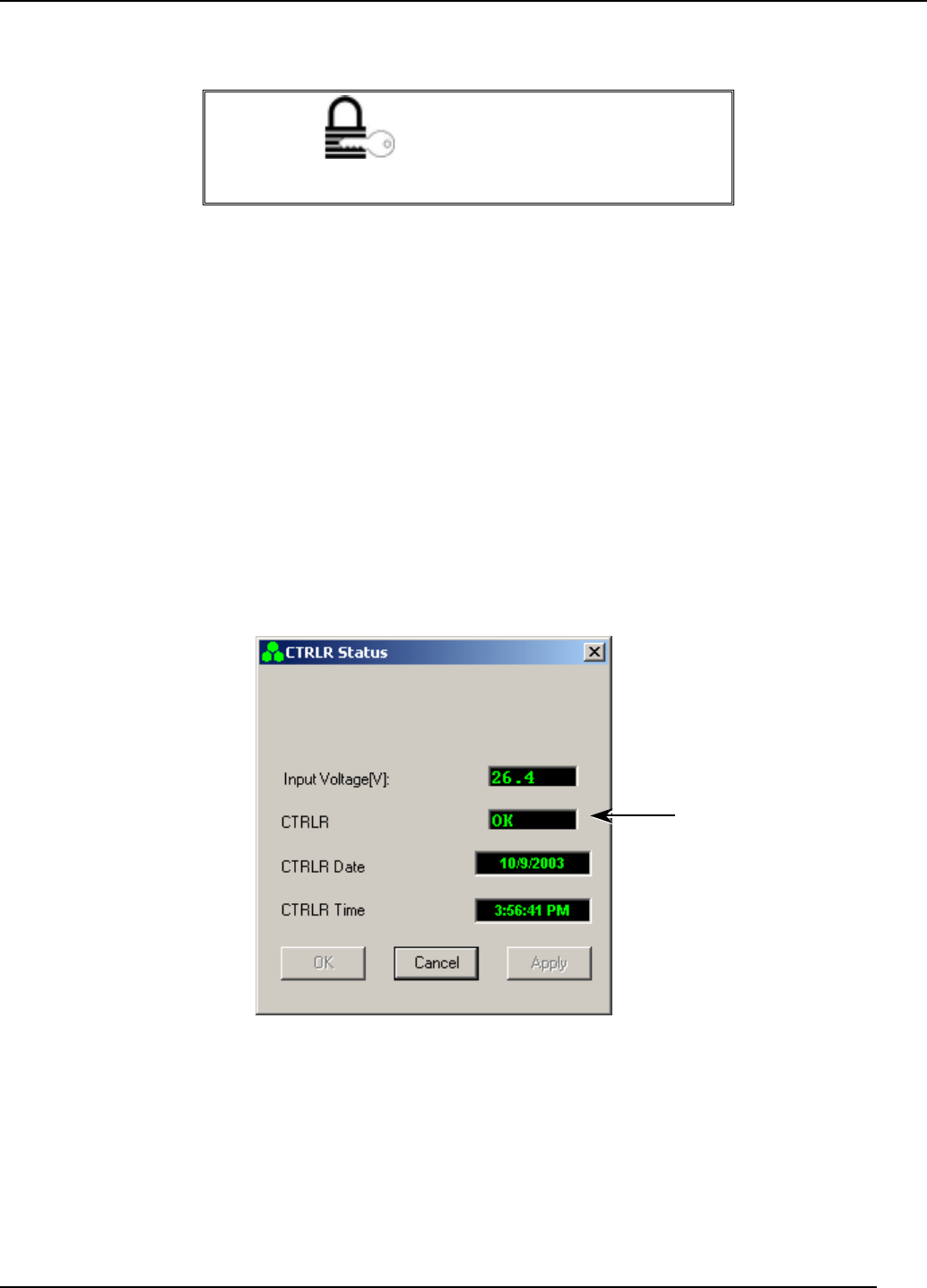
4.2.1 ICU Controller
Click Controller to make the screen in Figure 4-3 appear.
The screen consists of
• Controller card input voltage
• Controller card status
• Date
• Time
4.2.1.1 Input Voltage
The unit is functioning correctly when Input voltage is 24±4V.
Figure
4-3 CTRLR status high level
4.2.1.2 Date
To update the date:
1. Use the cursor to highlight the CTRLR Date box. If your current authorization
level is Operator or Supervisor, you are prompted to enter the Admin Password.
2. Press the Delete button on the keyboard.
Click the CTRLR field
to invoke the ICU
Controller Status
details window, shown
in Figure 4-4
Transmit Diversity Add-On System Assembly and Operation Manual
Document No. 913004500 Rev. 0.0 4-4 Celletra Proprietary
3. Click Apply twice. The Date updates automatically according to the date on your
PC.
4.2.1.3 Time
To update the time:
1. Use the cursor to highlight the CTRLR Time box. If your current authorization
level is Operator or Supervisor, you are prompted to enter the Admin Password.
2. Press the Delete button on the keyboard.
3. Click Apply twice. The time updates automatically according to the time on your
PC.
4. Click OK.
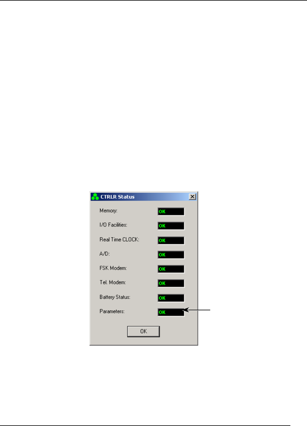
4.2.1.4 Controller Card Status
Figure 4-4 shows details of the controller status. This screen is invoked by clicking
the CTRLR field in Figure 4-3.
When all the parameters are OK, the unit is functioning correctly.
Figure
4-4 Controller status details
Click the Parameters field to
invoke ICU Controller
parameters window, shown in
Figure 4-5
Transmit Diversity Add-On System Assembly and Operation Manual
Document No. 913004500 Rev. 0.0 4-5 Celletra Proprietary
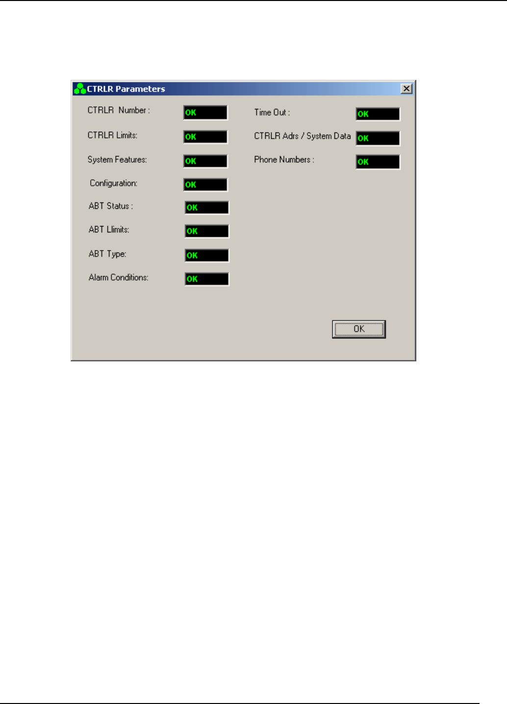
Figure 4-5 displays ICU Controller parameters. Invoke this screen by clicking the
Parameters field in Figure 4-4.
When all the parameters are OK, the unit is functioning correctly.
Figure
4-5 CTRLR parameters
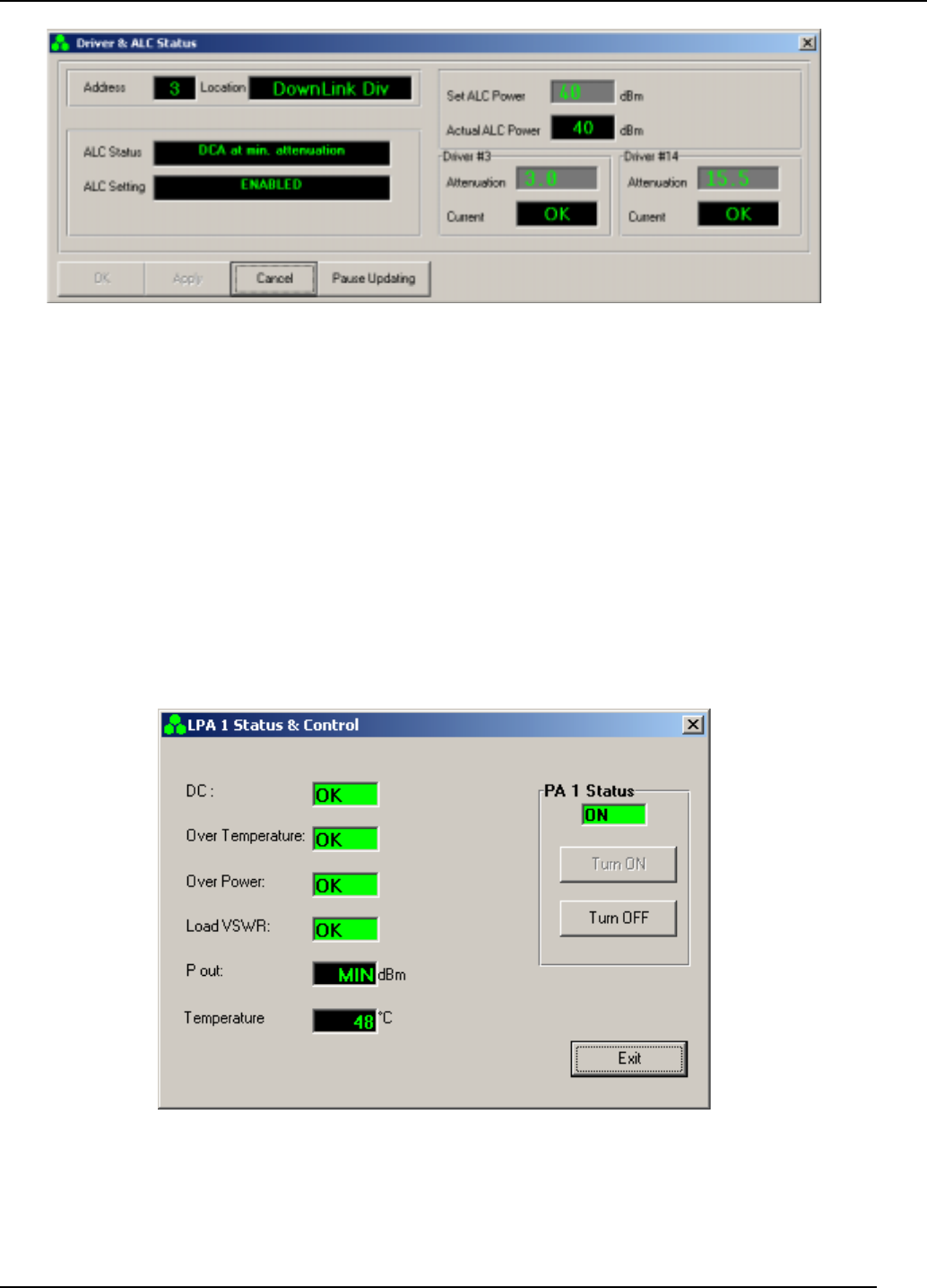
4.2.2 DLDL and Driver
Click DLDL and driver to open the screen shown in Figure 4-6. This screen enables
• Monitoring the Address and Location of the Driver
• Monitoring the ALC Status and setting
• Set ALC power level
• Monitoring Actual ALC power. When the Set ALC Power and the Actual ALC
Power are not equal the ALC (Automatic Level Control) is ON
• Changing the unit attentuator setting
• Monitoring the status of the Unit Current
Setting the attenuators is an advanced system optimization process.
Transmit Diversity Add-On System Assembly and Operation Manual
Document No. 913004500 Rev. 0.0 4-6 Celletra Proprietary
Figure
4-6 Driver & ALC Status
The unit is functioning correctly when
• Set ALC Power and Actual ALC Power are equal
• Current is OK
Click Pause Updating in order to change the ALC Power.
4.2.3 Power Amplifier (PA)
Click PA to make the screen in Figure 4-7 appear. This screen enables:
• monitoring of the P out and Temperature of the unit.
• Turn the PA ON or OFF
Figure
4-7 PA monitoring
The unit is functioning correctly when Pout range is 32dBm to 42dBm .
Click Turn OFF in order to switch the PA OFF. Click OK when the acceptance dialog
box appeare.Click Turn On in order to switch the PA ON.

Transmit Diversity Add-On System Assembly and Operation Manual
Document No. 913004500 Rev. 0.0 4-7 Celletra Proprietary
4.3 Calibration
This section describes the calibration procedure for the Transmit Diversity (TDA)
system. The objective of this procedure is to set the Tx power correctly in the
diversity path in respect to the main path, after the TDA system installation.
The TDA system calibration refers to the two transmission branches:
• Main Tx
• Diversity Tx
The Transmit Diversity mechanisim functions best with equal radiated power from
the main and diversity antennas. Moreover, the TDA system enables the overall Tx
power transmitted by the two transmission paths (main and diversity) to be higher
than that of the legacy BTS Tx power.
The overall sector power with the TDA system (including main and diversity) is
determined by the operator according to network planning. Once the main path is
calibrated by adjusting the BTS output power, the power to the diversity transmit
antenna is calibrated by adjusting the digital controllable gain of the TDA Unit via the
TSM software.
NOTE: All of the steps in the following calibration procedure are on a per
sector basis. Repeat all the steps for other sectors with the TDA system,
where applicable.
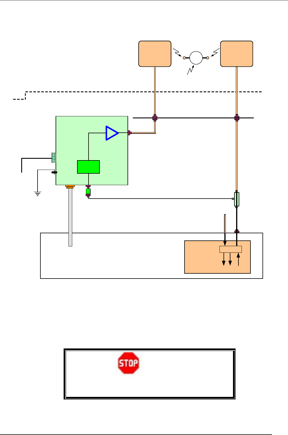
4.3.1 Main Tx
See Figure 4-8. Set the BTS output power as follows:
1. Verify that the station is transmitting.
2. Calculate Pout max. as per Section 2.5.4.
3. Record the main Pout max. as "Main Path Power with TDA System" as in
Appendix C.
NOTE: The calibration procedure involves just gains in Main and Diversity
branches. The power is recorded for reference only.
Transmit Diversity Add-On System Assembly and Operation Manual
Document No. 913004500 Rev. 0.0 4-8 Celletra Proprietary
TDA Unit
BTS (CDMA - Cellular)
Transmit
Diversity
Unit
TX
Diversity
Antenna
Tx1/Rx1
Outdoors
Shelter
FRM
Coupler
DPM
Rx2 Rx1 Tx1
CDMA, 1 carrier
TDU
-48VDC
Major
Alarm
N-M
N-M
N-M
N-M
TB - No connector
W1
W2
W3
7-F
7-M
W5
W6
N-M or 7-M
7-F
7-M
Cables
Panel
Ground
LPA
CB - TB
W7
TX/RX
Main
Antenna
Antennas
Installation
(Top-view)
Tower
Rx2
Diversity
Port
Attenuator
N-M
N-F
Power
Measurement
Equipment
LG3 LG2
LG1
TDA Gain
Figure
4-8 Tx measurements setup
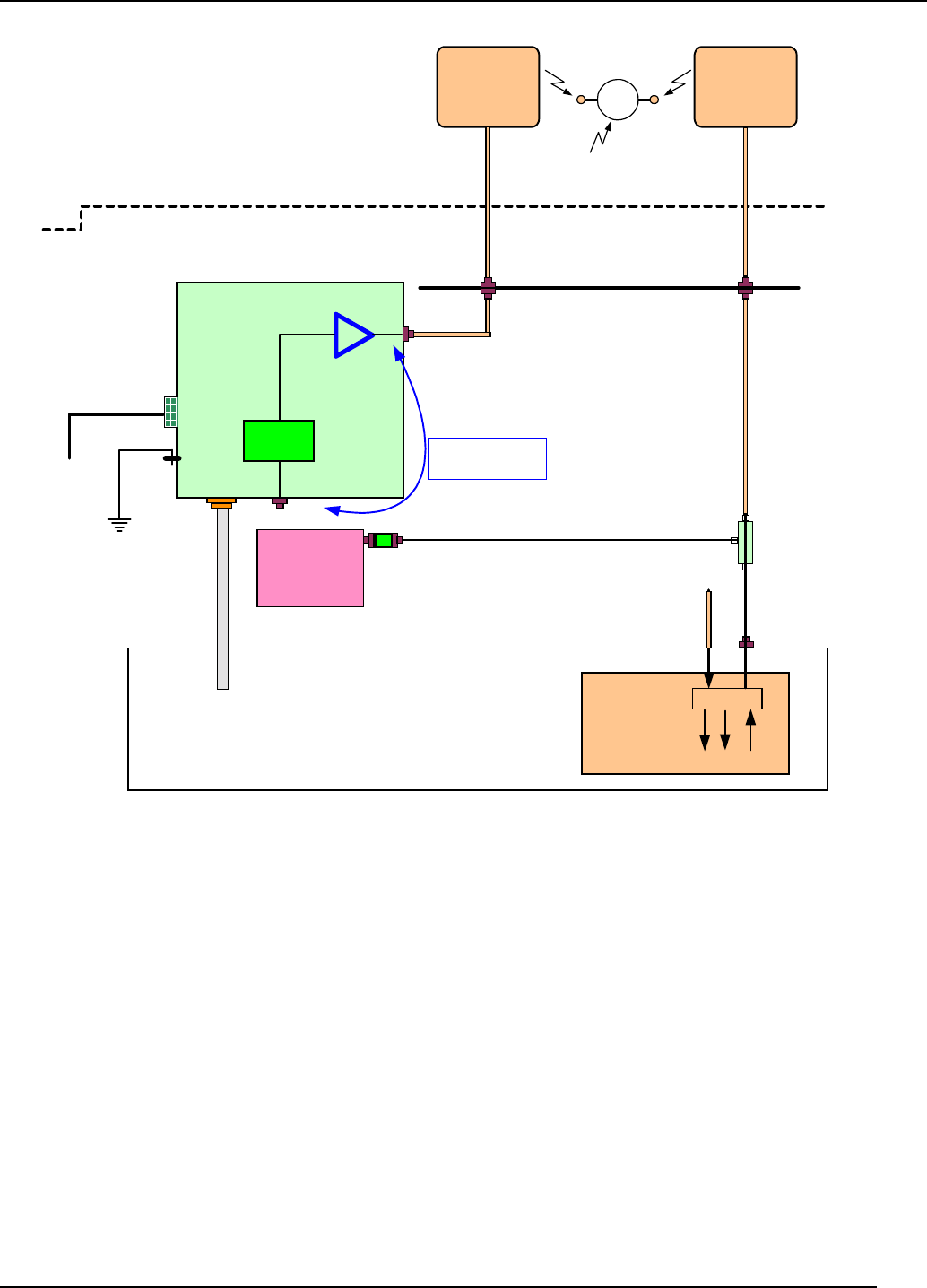
4.3.2 Diversity (TD) Tx Calibration
Calibrate the diversity path Tx power.
1. Click the Status and Control tab (Section 3.3.1).
2. Enter the Cable Loss [dB] (W5) according to Table 2-4, W5 Insertion loss [dB].
3. Read the Antenna “Output Power [dBm]” from the TSM screen.
Antenna Power [dBm] = Amplifier Power [dBm] – Cable Loss [dB]
Where the cable loss is a positive value in dB.
Transmit Diversity Add-On System Assembly and Operation Manual
Document No. 913004500 Rev. 0.0 4-9 Celletra Proprietary
Figure
4-9 TDA System: Number, Name, and Type
4. Get the main and diversity antennas and the coax cables data from the cable
shelf to the antennas. Look for the details belo:
• Cable types and lengths
• RF attenuations at operating frequency [dB]
• Antenna types [verify that both sector antennas are isentical]
5. Measure the RF loss for the main and diversity paths according to.
Main path loss = W2 + LG1+LG2 ≡ A
Diversity path loss= W2+Coupler Loss (30dB) + W3 + Att loss (20dB)+
+W5+LG3 ≡ B
Comments:
1. All losses (W2÷ W5, LG1÷ LG3) are positive values in dB
2. If adapter is used instead of W2 the loss is negligible
3. Coupler insertion loss is negligible
6. Calculate the TDA required gain (Downlink Gain [dB]) according to:
Set Gain [dB] = B – A
7. Set the Set Gain integer value in the Ststus and Control screen rounding up (B –
A).
8. Record the above Gain as " TDA Unit Downlink Gain Setting" in Appendix C.
Transmit Diversity Add-On System Assembly and Operation Manual
Document No. 913004500 Rev. 0.0 4-10 Celletra Proprietary
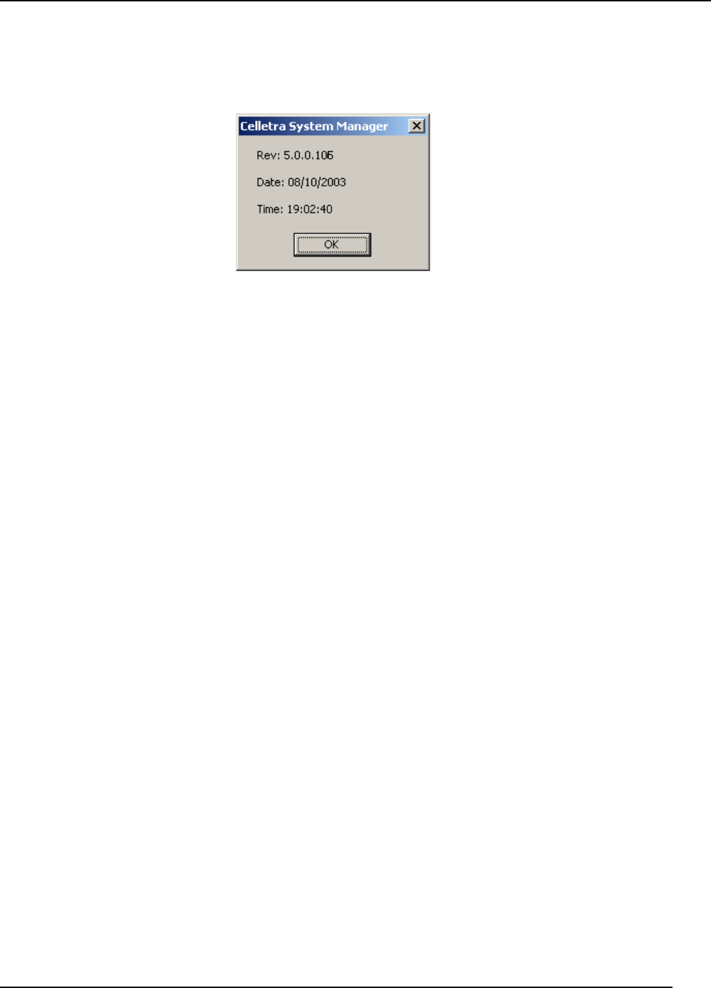
4.4 TSM Software Version
Select the About menu to view the TSM software version.
Figure
4-10 TSM software version
4.5 PC Disconnect from TDA Unit
1. Close TSM.
2. Disconnect the PC from the TDA Unit.

Document No. 913004500 Rev. 0.0 5-1 Celletra Proprietary
Chapter 5. Servicing and Troubleshooting
the TDA System
5.1 Servicing the TDA
The TDA system does not require any maintenance activities.
5.2 Troubleshooting
The following table details some common problems and recommended solutions.
NOTE: For unsolved problems or difficulties, contact Celletra Technical
Support at support@celletra.com
Table 5-1: Troubleshooting
Error/Fault Check
System not
responding to the
TSM
• Check that all the TDA - PC connectors are firmly connected.
• Verify proper installation and power connections to the TDA.
(Check AC or DC input voltage).
Monitoring and
control problems
• Check RS-232 cable connection; verify serial comm. port definition on
the TSM software.
• Check communication cable (For connector pin out refer to Appendix
B).
• Check the PC serial port.
Low/No RF Power Operate TSM software and check the following parameters:
• DC power level in the TDA
• System setup
• In/Out RF power
If the input seems OK yet the output is faulty, replace the unit and re-
configure the system setup.
System Alarms 1. In the Configuration screen, look for alarms in the unit, where the
frame may be colored red or yellow.
2. Drill down to the unit that shows a red or yellow frame.
3. If the PA is OFF, try to turn it ON.
4. If the PA does not go ON, replace the TDA unit.
Transmit Diversity Add-On System Assembly and Operation Manual
Document No. 913004500 Rev. 0.0 5-2 Celletra Proprietary
5.3 Log File
The log file records system events such as malfunctions or TDA powering-on.
AUTHORIZATION
Only Administrators can perform this procedure.
5.3.1 Access the Log
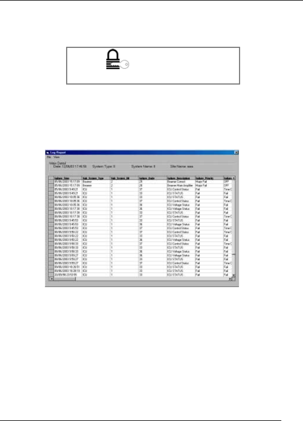
Access the log file by selecting Get ICU Log from the File menu in the TSM.
Following is an example of the log file display.
Figure
5-1 Log file
If no information is displayed, a serious communication problem is indicated.
You can manipulate the data stored and displayed using the menu bar shown at the
top of the log file screen.
To exit the log file, click Exit in the File menu.
For more information about a particular error, go to the System Configuration block
diagram and double-click the malfunctioning unit.
Transmit Diversity Add-On System Assembly and Operation Manual
Document No. 913004500 Rev. 0.0 5-3 Celletra Proprietary
5.3.2 Display the Log
The log file provides the following information for each event.
Name Explanation
Failure Time The time at which the event occurred.
Sub-System
Type
The unit where the event occurred.
Sub-System
HO
Logical address of the unit.
Failure Code Code (from the protocol)
Failure
Description
Describes the problem in brief, for example, ICU Control Status.
Failure Priority The failure severity assigned to the event, as described in Table B-3.
Options are "Fail" (minor) and "Major fail".
Failure Value Options are Fail, Timeout, Low, or Off.
BitStream Any relevant data from the bit stream.
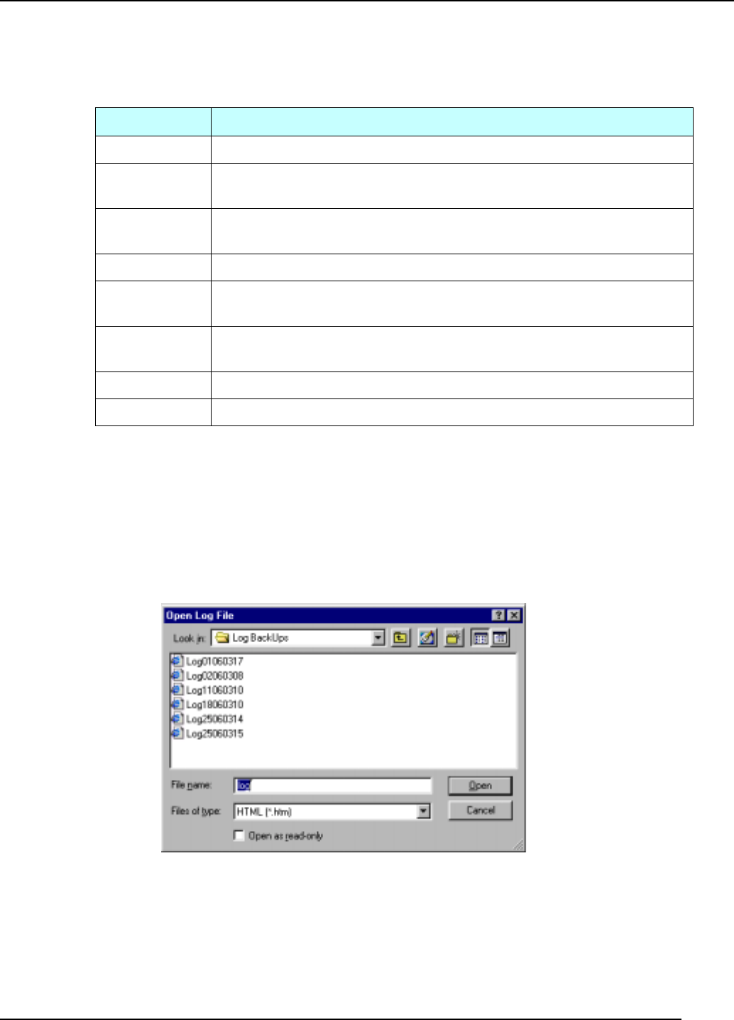
5.3.3 Store the Log
Every time you access the log file, the data is automatically stored to file and the log
is cleared. To see a list of log files and their creation dates, select Show All Files
from the View menu. You will see a dialog like this:
Figure
5-2 Log files list
Transmit Diversity Add-On System Assembly and Operation Manual
Document No. 913004500 Rev. 0.0 5-4 Celletra Proprietary
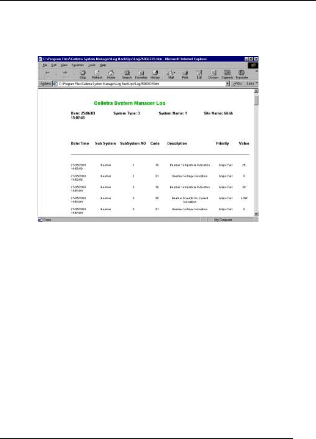
5.3.4 View as HTML
To view the log file in HTML format, click Show HTML Version in the View menu.
The resulting view may look something like this.
Figure
5-3 Log file as HTML
Document No. 913004500 Rev. 0.0 Appendix 1 Celletra Proprietary
APPENDIX A. DEFAULT SYSTEM LIMITS
Defining System Failure Conditions
Failure conditions are predefined by the manufacturer, as shown in the following
table:
Table A-2: Failure conditions
Failure Description Recommended Value
ABT voltage Minor
DLDU voltage Minor
ICU voltage Minor
ABT current Minor
DLDU current Minor
ICU current Minor
ICU Controller Minor
Fan current N/A
Document No. 913004500 Rev. 0.0 Appendix 2 Celletra Proprietary
APPENDIX B. CONNECTOR PINS
The following table shows the connector pins for RS-232 cable.
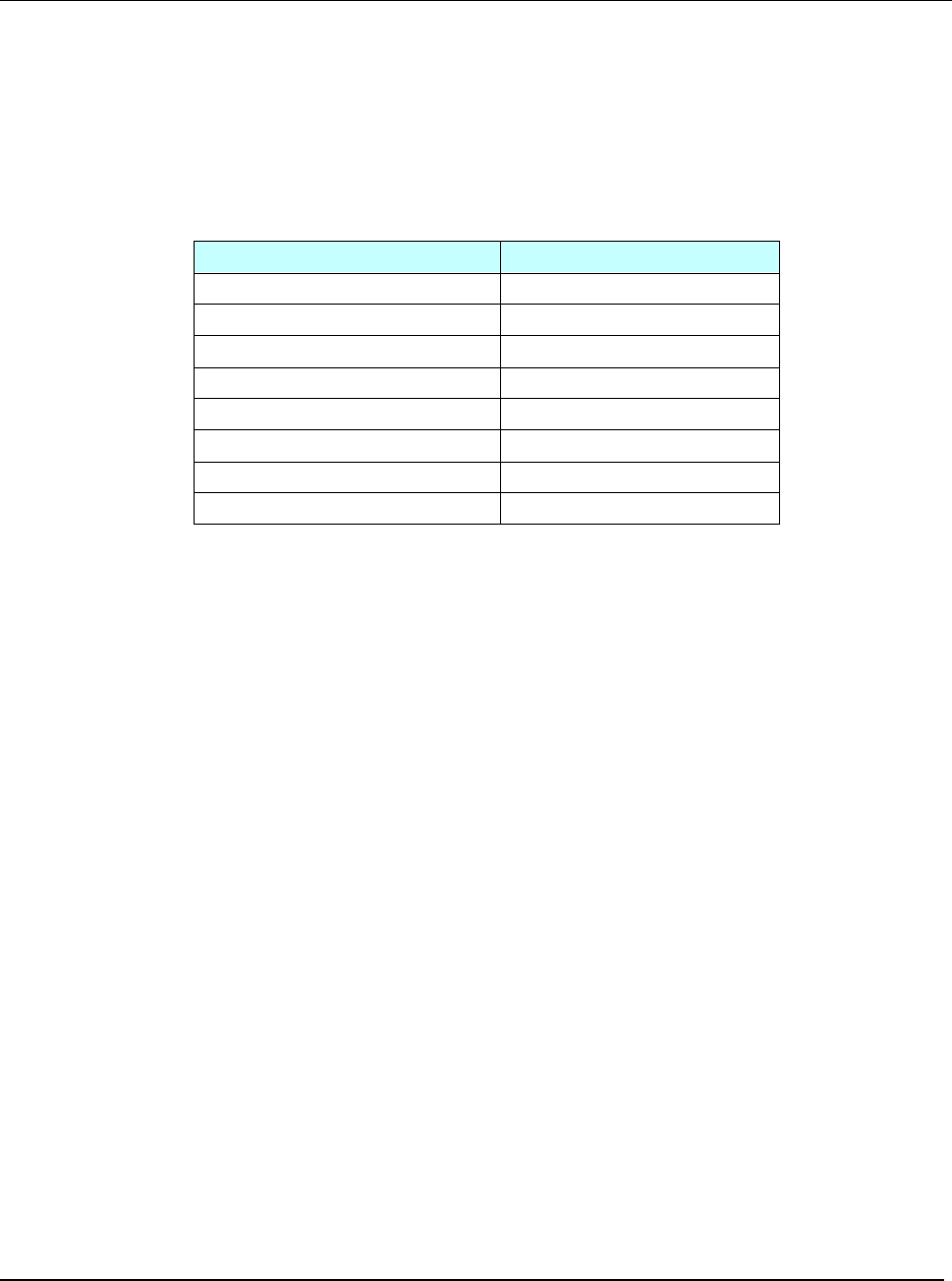
Table B-1: RS-232 and modem activation communication connector
Amphenol C16-1
Connector
(TDA side)
Communication Cable
(PC Side)
Pin # Function Pin # Function
1 Bypass return NA NA
2 Modem Rx NA NA
3 CTRLR Rx 3 Pc Tx
4 CTRLR Tx 2 PC Rx
5 NA NA NA
6 Modem Tx NA -
7 GND 5 GND
1 to 7 Jumper NA NA
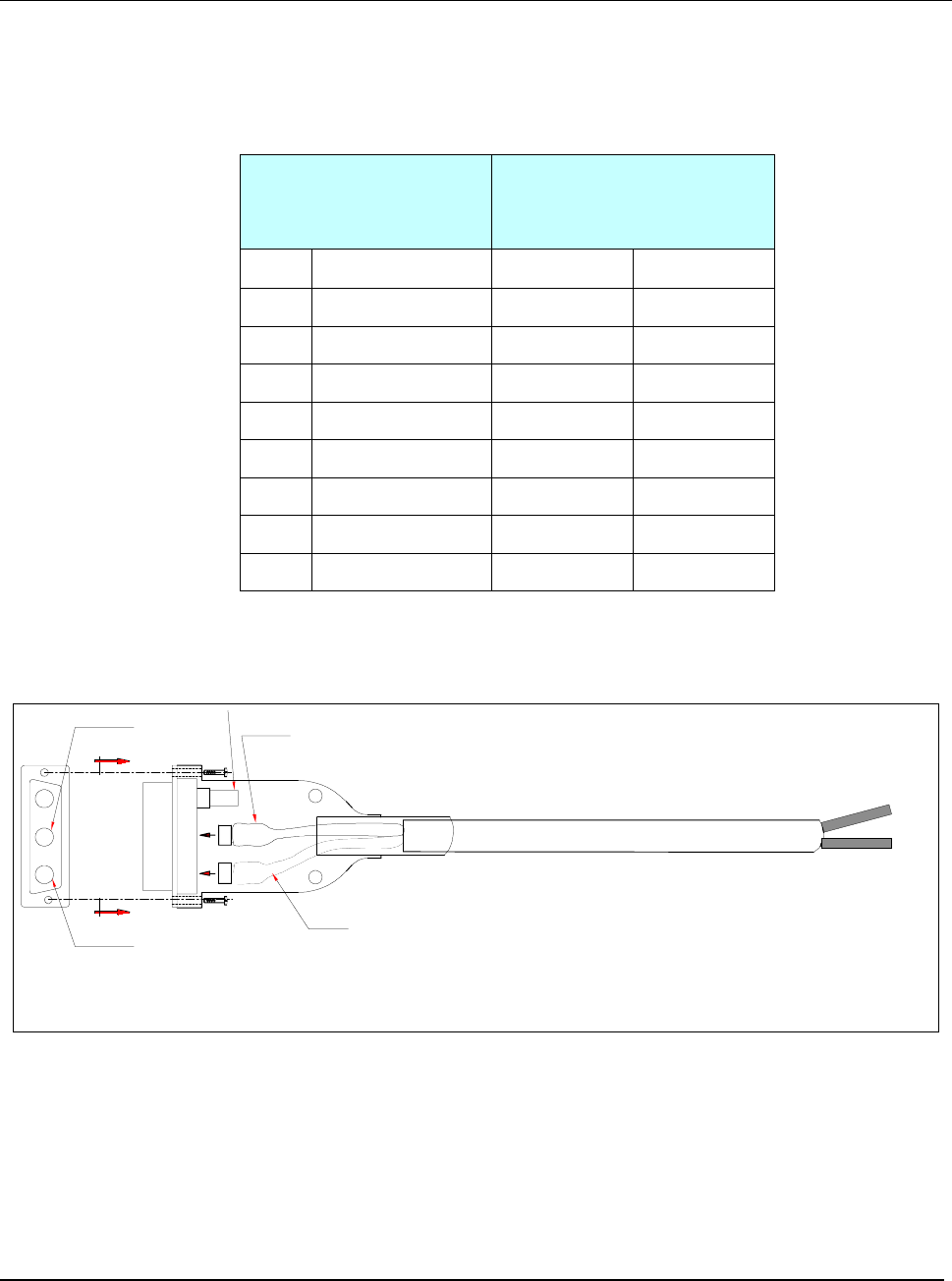
The following figure shows the DC power jumper cable layout.
A1A3 A2
BLACK
WHITE
WIRE
WIRE
A
A
PIN FOR
VIEW-A
A3 A2 A1
BLACK
PIN FOR
WHITE
WHITE 0VDC
BLACK -48VDC
Figure B-1 DC power jumper cable layout
Transmit Diversity Add-On System Assembly and Operation Manual
Document No. 913004500 Rev. 0.0 Appendix-3 Celletra Proprietary
APPENDIX C. RECORDS
TDA System Installation Record
After setting the TDA system, it is recommended to write down the site
information for remote control records.
TDA System # ........... ...................
TDA System Name.... ...................
Measured RF Cable Loss
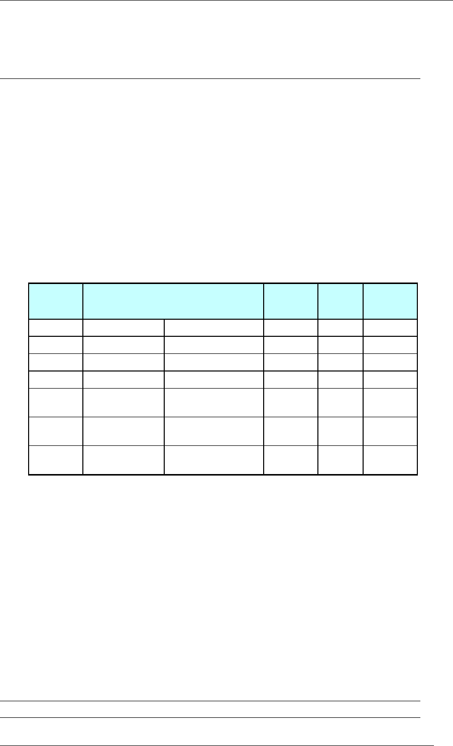
Table C-1: RF cables sweep test
Cable # Cable Description Insertion
Loss Return
Loss Remarks
From To
W2 FRM Tx1/Rx1 Coupler
W3 Coupler Attenuator
W5 TDA Unit Cable Panel DIV
LG1 Coupler Cable Panel Main Legacy
Cable
LG2 Cable Panel Main Tx/Rx Main Antenna Legacy
Cable
LG3 Cable Panel DIV Tx DIV Antenna Legacy
Cable
Main Path Power Before TDA System
Pout max. (Base-line) .. ................... dBm
Main Path Power With TDA System
Main Pout max. with TDA .............. dBm
TDA Unit Downlink Gain Setting
Set Gain .................... ................... dB
Updated by: ______________ Signature: ______________ Date: _____________