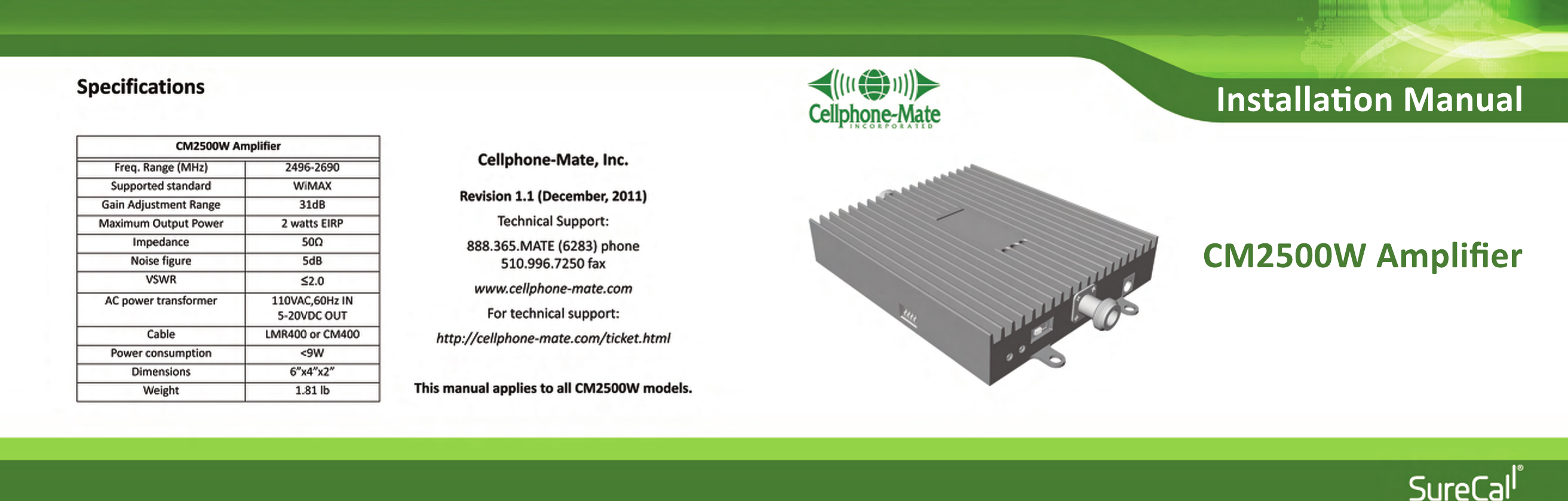
Cellphone Mate SureCall CM2500W WiMax Single Direction Amplifier User Manual

Cellphone-Mate Inc. dba SureCall WiMax Single Direction Amplifier Users Manual

Users Manual

Installaon ManualCM2500W Amplifier
Copyright 2011 Cellphone-Mate, Inc. All rights reserved. iCHAPTER 1: Introduction   - - - - - - - - - - - - - - - 11.1 - Package Contents  - - - - - - - - - - - - - - - - 11.2 - Features & Benefits - - - - - - - - - - - - - - - 21.3 - Additional Items Needed - - - - - - - - - - - 21.4 - How It Works   - - - - - - - - - - - - - - - - - - - 31.5 - About This Manual   - - - - - - - - - - - - - - - 3CHAPTER 2: Safety   - - - - - - - - - - - - - - - - - - - - 52.1 - Safety Warnings 5  - - - - - - - - - - - - - - - - - CHAPTER 3: Planning   - - - - - - - - - - - - - - - - - - 73.1 - Overview   - - - - - - - - - - - - - - - - - - - - - - 73.2 - Exterior Antenna - - - - - - - - - - - - - - - - - 83.3 - Interior Antennas  - - - - - - - - - - - - - - - - 93.4 - Antenna Separation   - - - - - - - - - - - - - 103.5 - Calculating Signal Strength   - - - - - - - - 133.6 - Amplifier Location - - - - - - - - - - - - - - - 143.7 - Accessories  - - - - - - - - - - - - - - - - - - - - 153.8 - Need Help? - - - - - - - - - - - - - - - - - - - - 16CHAPTER 4: Installation - - - - - - - - - - - - - - - - 174.1 - Selecting the Locations   - - - - - - - - - - -174.2 - Soft Installation  - - - - - - - - - - - - - - - - -174.3 - Exterior Antenna  - - - - - - - - - - - - - - - -174.4 - Internal Antennas   - - - - - - - - - - - - - - - 184.5 - Mounting the Amplifier  - - - - - - - - - - - 19CHAPTER 5: Configuration & Testing  - - - - - - 215.1 - DIP Switches and Lights  - - - - - - - - - - -215.2 - Initial Configuration  - - - - - - - - - - - - - -235.3 - Powering on the Amplifier  - - - - - - - - - 235.4 - Testing   - - - - - - - - - - - - - - - - - - - - - - - 245.5 - Adjusting the Amplifier   - - - - - - - - - - - 245.6 - Automatic Shutdown  - - - - - - - - - - - - - 26CHAPTER 6: Warranty  - - - - - - - - - - - - - - - - - 276.1 - Warranty Periods - - - - - - - - - - - - - - - -276.2 - Warranty Information  - - - - - - - - - - - -286.3 - Contact Information   - - - - - - - - - - - - -30CHAPTER 7: Regulatory Information  - - - - - - 317.1 - FCC Information   - - - - - - - - - - - - - - - -31Table of Contents
CM2500W Amplifier - Installation Manualii Copyright 2011 Cellphone-Mate, Inc. All rights reserved.Copyright & Trademark InformationTHIS MANUAL CONTAINS SAFETY, INSTALLATION, CONFIGURATION AND WARRANTY INFORMATIONFOR YOUR CELLPHONE-MATE, INC (CMI) AMPLIFIER. CMI RECOMMENDS THAT YOU SAVE THIS MAN-UAL IN A READILY ACCESSIBLE LOCATION IN CASE ANY QUESTIONS ARISE ABOUT THIS PRODUCT.Copyright © 2011 by Cellphone-Mate, Inc. All rights reserved. SureCall is a registered trademark andCellphone-Mate is a trademark of Cellphone-Mate, Inc. All other trademarks or registered trademarksare the property of their respective owners.
Copyright 2011 Cellphone-Mate, Inc. All rights reserved. 1This chapter introduces theCM2500W Amplifier and this manual.Read this entire manual before pro-ceeding with the installation. Thismanual is for all CM2500W models.1.1 - Package ContentsYour amplifier box contains the following items:• CM2500W amplifier.• Mounting kit (not shown).• DC power supply (not shown).• Wall anchors (not shown).CHAPTER 1: Introduction
CM2500W Amplifier - Installation Manual2Copyright 2011 Cellphone-Mate, Inc. All rights reserved.1.2 - Features & BenefitsThe CM2500W amplifier offers the following fea-tures and benefits:• Powerful in-building amplifier with 31dB ofadjustable gain level.• Extends cellular signals in areas with poor cov-erage due to geographical location and/orbuilding design.• Suitable for large areas up to about 30,000square feet depending on outside signalstrength and carrier frequency.• Sophisticated power control maintains maxi-mum output power at 2 watts EIRP.• Automatic oscillation detection and protec-tion system powers down the amplifier to pre-vent harmful radio interference (if equipped).1.3 - Additional Items NeededThe CM2500W amplifierrequires the followingadditional components fora complete installation:• 4G WiMAX compatibleantenna (such as theCM288-W omni orCM230-W Yagi by Cell-phone-Mate, Inc.)• Lightning protector(CMLP).• Cable splitter if install-ing multiple antennas(up to six in a typicalinstallation).
CHAPTER 1: IntroductionCopyright 2011 Cellphone-Mate, Inc. All rights reserved. 3• Sufficient CM400 ultralow loss interior/exte-rior cable (for amplifi-ers above 55dB).• Sufficient CM240 ultralow loss interior/exte-rior cable (for amplifi-ers 55dB and below).• Up to 6 internal anten-nas (such as theCM222-W omnidirec-tional domes and/orCM248-W directionalflat panel by Cell-phone-Mate, Inc.).• Grounded surge sup-pressor for DC powersupply.1.4 - How It WorksThe CM2500W amplifier boosts cellular signalsfrom the nearest cellular tower to phones in abuilding and from those phones back to the towerto compensate for weak reception caused by dis-tance, topography, building structure, and/orother reasons. The amplifier receives the signalfrom an outside antenna, amplifies that signal,and then rebroadcasts it via the interiorantenna(s) where it is picked up by cellularphones, modems, and data cards. The interiorantennas also pick up signals from cellular devicesand pass them to the amplifier. The amplifierboosts these signals and passes them to the exte-rior antenna for rebroadcast back to the tower.1.5 - About This ManualThis manual contains the following information:
CM2500W Amplifier - Installation Manual4Copyright 2011 Cellphone-Mate, Inc. All rights reserved.•Introduction:  This chapter introduces theCM2500W amplifier and this manual.•Safety: This chapter contains important safetyinformation.• Planning: This chapter describes how to planyour installation for best results.•Installation: This chapter describes how toinstall the amplification system.•Warranty: This chapter contains warrantyinformation for your amplification system.•Regulatory Information: This chapter containsimportant regulatory agency information.Lists of items or points to consider that need notbe performed in order appear in bullet format:• Item 1• Item 2Procedures that must be followed in a specificorder appear in numbered steps:1. Perform this step first.2. Perform this step second.This manual also contains important safety infor-mation and instructions in specially formattedcallouts with accompanying graphic symbols:WARNING: WARNINGS INDICATE THEPOSSIBILITY OF PERSONAL INJURY.CAUTION: WARNINGS INDICATE THEPOSSIBILITY OF EQUIPMENT DAMAGERADIO INTERFERENCE, ETC.Note: Notes provide helpful information.
Copyright 2011 Cellphone-Mate, Inc. All rights reserved. 5This chapter contains importantsafety information designed to pre-vent personal injury, equipment mal-function, and/or radio interference.You are responsible for ensuring asafe installation.2.1 - Safety Warnings• You are responsible for knowing and followingall applicable codes and regulations and forobtaining all required permits and inspections.• Follow all safety precautions contained in thisInstallation Manual.• The installation process may require workingin high locations such as roofs and/or ladders.Follow applicable safety regulations and bestpractices to avoid falling. Take care not to dropobjects off any high area. Cordon off groundareas directly below roof or ladder work whenpossible.• Always use appropriate personal protectiveequipment such as goggles, gloves, hard hat,etc. as needed and as required.WARNING: FAILURE TO EXERCISE CAU-TION WHEN WORKING IN HIGH AREASCOULD CAUSE A FALL AND PERSONALINJURY.CHAPTER 2: Safety
CM2500W Amplifier - Installation Manual6Copyright 2011 Cellphone-Mate, Inc. All rights reserved.• Some components may be heavy and/orbulky. Always use proper lifting and carryingtechniques when handling components, espe-cially when working on a ladder, roof, or otherarea with a fall hazard.• The exterior antenna must not be co-locatedor operating in conjunction with any otherantenna.• Always use a properly installed Cellphone-Mate lightning protector between the exteriorantenna and the amplifier. CAUTION: FAILURE TO PROPERLYINSTALL A LIGHTNING PROTECTOR CANRESULT IN DAMAGE TO THE AMPLIFIER,ANTENNAS, AND WIRING.• Always power off the amplifier before workingon the roof of the building or anywhere inclose proximity to the external antenna.• Allow at least 24 inches (60cm) of separationbetween interior antennas and humans or ani-mals.• Allow at least 24 inches (60cm) of separationbetween exterior antennas and all persons.• Comply with all antenna separation require-ments to prevent signal oscillation.CAUTION: SIGNAL OSCILLATION CANCAUSE RADIO INTERFERENCE WITHCELLULAR TOWERS AND RESULT INCIVIL AND/OR CRIMINAL PENALTIES.
Copyright 2011 Cellphone-Mate, Inc. All rights reserved. 7This chapter describes how to planyour amplifier installation, includinghow to determine the best locationsfor the inside and outside antennas.3.1 - OverviewThe general amplifier installation process followsthese steps:1. Decide where to mount the exterior antenna.This will generally be on the wall or roof of thebuilding in the location with the strongest sig-nal. You will need to decide whether to use anomnidirectional antenna mounted verticallyor a directional Yagi antenna pointed directlyat the cellular tower (line of sight). You mustalso consider attaching a grounded lightningprotector between the exterior antenna andthe amplifier.2. Decide where to mount the interiorantenna(s), being sure to take separationrequirements into account. In general, longnarrow spaces will benefit most from direc-tional flat-panel antennas while more squarespaces will benefit more from omnidirectionaldome antennas.3. Decide where to mount the amplifier. Thisshould be in a secure indoor location near agrounded power source.CHAPTER 3: Planning
CM2500W Amplifier - Installation Manual8Copyright 2011 Cellphone-Mate, Inc. All rights reserved.4. Decide where to route the cables between theexterior antenna and the amplifier andbetween the amplifier and interior antennas.5. Install the antennas as described in theirrespective Installation Manuals.6. Route the cables to the amplifier location.7. Install the amplifier as described in this man-ual.8. Power on the amplifier and perform the con-figuration and testing as described in thismanual.3.2 - Exterior AntennaYou may use either an omnidirectional antennasuch as the CM288-W (flat area with no obstruc-tions) or a directional Yagi antenna such as theCM230-W (to point directly at the tower). Theomnidirectional antenna receives and transmitssignals over a horizontal 360-degree circle whilethe Yagi antenna receives and transmits signalsover a focused area and must be aimed directly(line of sight) toward the cellular tower that pro-vides the best signal to the building.The exterior antenna and mast (if any) must bemounted in a location that meets all of the follow-ing criteria:• Best signal strength.
CHAPTER 3: PlanningCopyright 2011 Cellphone-Mate, Inc. All rights reserved. 9• Not collocated with other antennas or used inconjunction with other antennas.• Away from all power lines.• 6’ from lightning rod antennas.• 24” from all persons.These distances are general guidelines only; referto the applicable building and electrical codes inyour area to determine local requirements.3.3 - Interior AntennasYou may use any combination of omnidirectional(dome) and/or directional (flat panel) interiorantennas needed to obtain optimal signalstrength throughout the building or installationarea. Dome antennas such as the CM222-W pro-vide 360-degree hemispherical coverage suitablefor mostly square areas while flat panel antennassuch as the CM248-W provide a focused zone ofcoverage suitable for long narrow areas. The fol-lowing example uses two dome antennas and onepanel antenna to provide full coverage (exteriorYagi antenna also shown):
CM2500W Amplifier - Installation Manual10 Copyright 2011 Cellphone-Mate, Inc. All rights reserved.Keep in mind that floor structures in multistorybuildings can cause significant signal loss, whichmeans that you may need to install interior anten-nas on more than one floor. Here is an example ofa multistory installation:Note: You may or may not need anten-nas on every floor of a multistory build-ing depending on factors such asbuilding material, amplifier gain, etc.3.4 - Antenna SeparationProper antenna separation is essential in order toprevent signal oscillation (feedback) that caninterfere with the cellular tower. Separation ismeasured in a straight line from the exteriorantenna to the closest interior antenna. The clos-est allowable distance depends on a number offactors such as amplifier gain level, building mate-rial, etc. Recommended separation distances are:Amplifier gain Min. separation (ad)40dB 6-7’45dB 18-25’50dB 60’55dB 71’65dB 88-95’70dB 117’
CHAPTER 3: PlanningCopyright 2011 Cellphone-Mate, Inc. All rights reserved. 11The easiest way to calculate the straight-line sepa-ration between antennas is to break it down intothree simple measurements and then use somebasic geometry to find the distance, as follows:1. Measure the distances ab,  bc, and cd asshown in the diagram on the next page.- Distance from the nearest interior antenna(Point a) to the wall underneath the exte-rior antenna (Point b). This is distance ab.Note: Vertical separation is more impor-tant than horizontal separation. If youare unable to obtain the required sepa-ration horizontally, try raising the exte-rior antenna. You may also try reducingthe amplifier gain as described in Chap-ter 5 of this manual.- Distance from Point b to directly under-neath the exterior antenna. This is Point(c). This is distance bc.- Distance from Point c to the exteriorantenna (Point d). This is distance cd.2. Multiply ab times ab to obtain ab2.3. Multiply bc times bc to obtain bc2.4. Multiply cd times cd to obtain cd2.5. Add ab2+bc2 to obtain ac2.6. Add ac2+cd2 to obtain ad2.
CM2500W Amplifier - Installation Manual12 Copyright 2011 Cellphone-Mate, Inc. All rights reserved.7. The straight-line distance ad is the square root() of the result obtained in Step 6.Example:• Distance ab=40 feet; ab2 = 40x40=1600.• Distance bc=10 feet; bc2 = 10x10=100.• Distance cd=20 feet; cd2 = 20x20=400.•ac2 = 1600+100=1700•ad2 = 1700+400=2100•ad = 45.83’Here, the straight-line distance ad is just under 46feet, which is compatible with 50dB amplifier gainas indicated in the previous table.Note: Most calculators have a squareroot () key.Separate interior antennas based on the calcula-tions shown in Section 3.5. You may mix andmatch dome and directional antennas as neededto obtain proper coverage throughout the build-ing or area where you need to boost the signal.If you are using aYagi exterior ant-enna, you shouldnormally aim it awayfrom all interiorantennas regardlessof separation to pre-vent oscillation.CAUTION: SIGNAL OSCILLATION CANCAUSE RADIO INTERFERENCE WITHCELLULAR TOWERS AND RESULT INCIVIL AND/OR CRIMINAL PENALTIES.
CHAPTER 3: PlanningCopyright 2011 Cellphone-Mate, Inc. All rights reserved. 133.5 - Calculating Signal StrengthYou can calculate the number of antennas you willneed using the following parameters (in dB):•Outside signal level (OSL): This is the signalstrength at the exterior antenna location andwill always be a negative number that will usu-ally fall between -50 and -100dBm. Calls willdrop at levels of about -100dB and lower.•Outside antenna gain (OAG): This the signalboost provided by the exterior antenna and isalways a positive number with Cellphone-Mate antennas.OAG 2500MHz WiMAXCM288-W omni +3CM230-W Yagi +10•Inside antenna gain (IAG): This is the signalboost provided by an interior antenna and isalways a positive number with Cellphone-Mate antennas.•Cable loss (CL): This is the signal loss causedby the cable and is always a negative number.IAG 2500MHz WiMAXCM222-W omni dome +3CM248-W directional panel+7CL 2500MHz WiMAX20’ CM400/CM240 -2.5/-5.030’ CM400/CM240 -2.5/-5.050’ CM400/CM240 -5.0/-10.0100’ CM400/CM240 -5.0/-10.0
CM2500W Amplifier - Installation Manual14 Copyright 2011 Cellphone-Mate, Inc. All rights reserved.•Splitter loss (SL): This is the signal loss causedby a splitter (used if you are installing multipleantennas).•Amplifier gain (AG): Number of decibels ofamplification provided by the amplifier (ratedgain less any attenuation, as described inChapter 5 of this manual). This is always a pos-itive number.The signal strength S at an interior antenna equalsOSL+OAG+IAG+CL+SL+AG. To calculate theapproximate coverage distance of each antenna:1. Calculate the signal strength S for the firstinterior antenna using the preceding formula.SL 2500MHz WiMAX2-way -33-way -54-way -62. Find the signal strength S for the antennaalong the bottom of the graph on the follow-ing page.3. Move straight up the signal strength line tothe PCS and cellular curves.4. Read the approximate coverage radius on theleft.3.6 - Amplifier LocationSelect an indoor location for the amplifier thatmeets the following criteria:• Wall or ceiling mounts are acceptable.• Near a properly grounded 110VAC outlet.• Not in a tightly enclosed or overly hot space.• All power and warning lights easily visible.• Least amount of cable to connect all antennas.
CHAPTER 3: PlanningCopyright 2011 Cellphone-Mate, Inc. All rights reserved. 153.7 - AccessoriesThe final step in the planning process is to makesure you have all of the necessary accessories tocomplete the installation. You will need all of theitems listed in Chapter 1 of this manual plus someor all of the following:•Cable clips: Use these to secure the cables tointerior and exterior walls/ceilings.•Appropriately rated sealant/caulking: Usethis to waterproof the opening where thecable from the exterior antenna enters thebuilding, if needed.•Hand and/or power tools: As needed to com-plete the installation.
CM2500W Amplifier - Installation Manual16 Copyright 2011 Cellphone-Mate, Inc. All rights reserved.•Personal Protective Equipment (PPE): Use allPPE required by local codes and/or best prac-tices to help ensure personal safety duringinstallation.Note: You may need to obtain a permitfrom your local building department toinstall the amplifier and antennas.Check your local building and/or electri-cal codes. You do not need any permitsfrom the FCC or the cellular carrier.CAUTION: YOU ARE RESPONSIBLE FORENSURING THAT THE INSTALLATIONMEETS ALL APPLICABLE CODES.3.8 - Need Help?If you need help planning your installation, pleasecontact a qualified installer, the reseller fromwhom you purchased the amplifier, or Cellphone-Mate, Inc.
Copyright 2011 Cellphone-Mate, Inc. All rights reserved. 17This chapter describes how to installthe amplifier and antennas for bestresults.4.1 - Selecting the LocationsSelect the locations for the exterior antenna, inte-rior antenna(s), amplifier, cables, and accessoriesas described in the previous chapter.CAUTION: FAILURE TO PROPERLY PLANTHE AMPLIFIER INSTALLATION CANCAUSE SIGNAL OSCILLATION AND/OROTHER EQUIPMENT MALFUNCTION.4.2 - Soft InstallationPerform a “soft” installation of all components totest signal coverage and oscillation before makingthe installation permanent. Avoid making holes orother permanent fixtures during this initial phase.Please refer to Chapter 5 of this manual for config-uration and testing instructions. Proceed with thefinal installation once configuration and testingare complete.4.3 - Exterior AntennaMount the exterior antenna in the location youselected during the planning process. Be sure tofollow all of the instructions included with theantenna to ensure a safe installation. Remember:CHAPTER 4: Installation
CM2500W Amplifier - Installation Manual18 Copyright 2011 Cellphone-Mate, Inc. All rights reserved.• An omnidirectional antenna (CM288-W) mustbe mounted vertically.• A Yagi antenna (such as the CM230-W) mustbe mounted horizontally and be aimed at thedesired cellular tower (line of sight).CAUTION: MOUNT THE EXTERIORANTENNA ON A FIXED STRUCTURE .WARNING: FAILURE TO EXERCISE CAU-TION WHEN WORKING IN HIGH AREASCOULD CAUSE A FALL AND PERSONALINJURY.WARNING: DO NOT TOUCH ANY LIVEELECTRICAL WIRES OR ALLOW THEANTENNA OR CABLING TO TOUCH ANYLIVE ELECTRICAL WIRES.1. Mount the antenna.2. Connect a length of CM400 cable to theantenna and tighten until hand-tight.3. Run the cable along the planned route.4. Install a properly grounded CMLP lightningprotector.5. Seal any holes you make in the outside of thebuilding with appropriate caulking or sealant.4.4 - Internal AntennasMount the interior antenna(s) in the location(s)you selected during the planning process. Be sureCAUTION: AVOID AIMING A YAGIANTENNA TOWARD ANY INTERIORANTENNA .
CHAPTER 4: InstallationCopyright 2011 Cellphone-Mate, Inc. All rights reserved. 19to follow the instructions included with theantenna(s) for a safe installation. Remember:• Dome antennas (CM222-W, etc.) should bemounted in the ceiling as close to the centerof the desired coverage area as possible withthe domed side pointing down.• Flat panel antennas (CM248-W) should bewall-mounted as close as possible to center ofthe wall at one end of long narrow space.1. Mount the antenna.CAUTION: VERIFY THAT ALL INTERIORANTENNAS MEET THE SEPARATIONREQUIREMENTS DESCRIBED IN THEPREVIOUS CHAPTER AND THAT NOANTENNA IS AIMED TOWARD THEEXTERIOR ANTENNA .2. Connect a length of CM400 or CM240 cable tothe antenna and tighten until hand-tight.3. If you are installing multiple antennas, run thecable to the splitter location and connect thecable to one of the outputs on the splitter.4. Connect another length of CM400 or CM240cable to the input side of the splitter (if used)and run this cable to the amplifier location.4.5 - Mounting the AmplifierMount the amplifier as follows:1. Verify that the selected location meets all ofthe criteria described in the previous chapter.CAUTION: DO NOT CONNECT ANINTERIOR ANTENNA TO THE SPLITTERINPUT.
CM2500W Amplifier - Installation Manual20 Copyright 2011 Cellphone-Mate, Inc. All rights reserved.2. Attach the included mounting kit to the ampli-fier using the screws provided. Tighten thescrews by hand with a screwdriver until snugplus 1/4 to 1/2 turn. Do not over-tighten.3. Mount the amplifier to the wall using appro-priate screws and/or wall anchors. The topside of the amplifier with the lights and DIPswitches should be facing up and be plainlyvisible when standing near the amplifier.4. Connect the exterior antenna cable to theOutside Antenna port on the amplifier.5. Connect the interior antenna cable to theInside Antenna port on the amplifier.6. Verify that all cable connections are snug andthat the exterior and interior antennas areconnected to the proper jacks. CAUTION: DO NOT POWER ON THEAMPLIFIER UNTIL INSTRUCTED TO DOSO.CAUTION: NEVER POWER ON THEAMPLIFIER WHEN ANY ANTENNAS AREDISCONNECTED AS THIS COULD DAM-AGE THE AMPLIFIER.
Copyright 2011 Cellphone-Mate, Inc. All rights reserved. 21This chapter describes how to poweron, configure, and test the amplifier.5.1 - DIP Switches and LightsThe CM2500W amplifier has the following indica-tors and controls:• Gain DIP switches (1): These DIP switches con-trol the amplification gain.• Warning light (2): This light illuminates whensignal oscillation is occurring.• Power light (3): This light should always beilluminated or blinking green while the ampli-fier is powered on.• Power switch (4): Allows you to turn theamplifier on and off.When the amplifier is plugged in and powered on:• The green Power light (3) should illuminate.CHAPTER 5: Configuration & Testing
CM2500W Amplifier - Installation Manual22 Copyright 2011 Cellphone-Mate, Inc. All rights reserved.• The red Warning light (2) should remain OFF.If the Warning light illuminates, power off theamplifier immediately.The bank of DIP switches on theside of the amplifier contains fiveswitches. • Moving a switch down(toward from the base of the amplifier) turnsthat switch OFF and increases amplifier gainfor the selected channel.• Moving a switch up (away from the base ofthe amplifier) turns that switch ON anddecreases amplifier gain for the selected chan-nel.From left to right, the DIP switches provide 1, 2, 4,8, and 16 dB of attenuation (reduced amplifica-tion). These switches are cumulative, meaningthat the total amount of attenuation for a channelis equal to the combined dB of all ON DIPswitches. For example:• Turning all switches OFF = 0dB attenuation(amplifier is at full gain).• Turning ON Switch #1 = 1dB attenuation(amplifier maximum gain is reduced by 1dB).• Turning ON Switches #1, 3, and 5 = 1+4+16dBattenuation = 21dB attenuation. For example,in a 70dB amplifier, this means that theselected channel would be reduced to 49dB(70db-21db).• Turning ON all switches = 1+2+4+8+16dBattenuation = 31dB attenuation. For example,in a 70dB amplifier, that means that theselected channel would be reduced to 39dB(70dB-31dB).
CHAPTER 5: Configuration & TestingCopyright 2011 Cellphone-Mate, Inc. All rights reserved. 235.2 - Initial ConfigurationBy default, your amplifier ships with all DIPswitches turned OFF to provide maximum gain inall channels. This should always be your startingpoint whenever installing or reinstalling theamplifier.5.3 - Powering on the AmplifierTo power on the amplifier:1. Make sure both antenna cables are snuglyconnected to the proper amplifier ports.2. Plug a surge suppressor into a grounded110VAC wall outlet.3. Plug the AC end of the power adapter thatcame with the amplifier into the surge sup-pressor.4. Plug the DC end of the power adapter into thePower port on the amplifier5. Power on the amplifier using the Powerswitch.6. Verify that the green Power light is illumi-nated.7. If the red Warning light illuminates, immedi-ately power off the amplifier by either unplug-ging the DC power supply from the surgesuppressor or by turning off the switch on thesurge suppressor. Increase the attenuationCAUTION: ONLY USE THE POWER SUP-PLY INCLUDED WITH THE AMPLIFIER.USE OF ANOTHER POWER SUPPLYCOULD DAMAGE THE AMPLIFIER AND/OR POWER SUPPLY.
CM2500W Amplifier - Installation Manual24 Copyright 2011 Cellphone-Mate, Inc. All rights reserved.(reduce gain). If you are at maximum attenua-tion and still receiving a warning, then youmust verify that all antennas have been placedaccording to these instructions and relocateantennas as needed to eliminate the oscilla-tion. See Section 5.6 for more information.8. Once the amplifier is powered on and the redWarning light is not illuminated, you may pro-ceed to adjust the amplifier.CAUTION: DO NOT PROCEED BEYONDTHIS POINT UNTIL THE AMPLIFIER ISPOWERED ON AND NO RED WARNINGLIGHTS ARE ILLUMINATED.5.4 - TestingOnce the amplifier is powered on and the Warn-ing light is not illuminated, walk around the entirearea to test the voice and/or data signal. Refinethe antenna locations and/or gain levels asneeded, and then complete the permanent instal-lation once the system is working as desired.5.5 - Adjusting the AmplifierKeep the following points in mind when adjustingthe amplifier:• Full gain is not always your best option. Yourgoal is to obtain a usable cellular signal in asmany areas of the building as possible. A suc-cessful installation means that you can makecalls without dropping and/or have a reliabledata connection.
CHAPTER 5: Configuration & TestingCopyright 2011 Cellphone-Mate, Inc. All rights reserved. 25• Do not expect to see 5 bars of receptioneverywhere in the building as this is practicallyimpossible. Also, signal strength in dB can varysignificantly without necessarily affecting thenumber of bars displayed because differentphone and data card manufacturers handlebars sightly differently.• A good rule of thumb is that increasing gain by6dB doubles the coverage distance of the inte-rior antennas. Start at the lowest gain settingand increase gain gradually as needed.• If the red Warning light comes on, oscillationis either happening or is about to happen andprotection circuits are activating (if equipped).If oscillation is or becomes severe, the ampli-fier will power down and will then wake every30 seconds for the next 15 minutes to see ifthe problem has been resolved. If the problemhas not been resolved after 15 minutes, theamplifier will shut off and will need to beunplugged and plugged back in again to reset.• If you can’t get the system to work properly,you may need to install an additional interiorantenna and/or a different type of interiorantenna and/or relocate interior antennas.
CM2500W Amplifier - Installation Manual26 Copyright 2011 Cellphone-Mate, Inc. All rights reserved.5.6 - Automatic ShutdownIf equipped, the CM2500W amplifier includes anautomatic shutdown feature that works in the fol-lowing sequence:1. When oscillation is detected in the uplink and/or downlink, the Warning light will beginflashing red and the Power light will turn red.2. If the problem is not resolved, the amplifierwill shut down after 30 seconds.3. The amplifier will wake back up. When thisoccurs, the Power light will be green. If oscilla-tion resumes, the lights will flash as previouslydescribed. These 30-second cycles will con-tinue for 15 minutes or until the problem isresolved.4. If the problem is not resolved within 15 min-utes, the amplifier will shut down (all lights offexcept the Power light, which is red) and mustbe reset by unplugging it from the power sup-ply and plugging it back in.To resolve oscillation, increase the antenna sepa-ration (Section 3.4) and/or the attenuation (Sec-tion 5.1).
Copyright 2011 Cellphone-Mate, Inc. All rights reserved. 27This chapter contains the warrantyinformation for your CELLPHONE-MATE product and also containsinformation on how to contact thecompany.6.1 - Warranty PeriodsYour warranty includes the following periods:•Two-Year Product Warranty: CELLPHONE-MATE products are covered under a two-yearproduct warranty from the date of purchase.This protects the customer from any defectsor problems the product may have that aresolely the fault of CELLPHONE-MATE Inc.Incorrect installation or misuse will void thiswarranty. Upon the return of a defective prod-uct, CELLPHONE-MATE will issue the customera working replacement. All returned packagesshould contain all products distributed.•Five-Year Extended Product Warranty: A fiveyear warranty is available for purchase on anyproducts sold by CELLPHONE-MATE Inc. A five-year warranty must be obtained at the time ofpurchase. This warranty adds an additionalthree years to the two year warranty we pro-vide. All regulations still apply.CHAPTER 6: Warranty
CM2500W Amplifier - Installation Manual28 Copyright 2011 Cellphone-Mate, Inc. All rights reserved.6.2 - Warranty Information1. CELLPHONE-MATE, Inc. warrants to the Buyerthat each of its products will be free fromdefects in material and workmanship and willperform in full accordance with applicablespecifications when shipped. The limit of lia-bility under this warranty is, at CELLPHONE-MATE, Inc.’s option, to repair or replace anyproduct or part thereof which shall, withinTWO YEARS of purchase as determined byexamination by CELLPHONE-MATE, Inc., provedefective in material and/or workmanship.Warranty returns must first be authorized inwriting by CELLPHONE-MATE, Inc. Disassemblyof any CELLPHONE-MATE, Inc. product by any-one other than an authorized representativeof CELLPHONE-MATE, Inc. voids this warrantyin its entirety. CELLPHONE-MATE, Inc. reservesthe right to make changes in any of its prod-ucts without incurring any obligation to makethe same changes on previously deliveredproducts.2. As a condition of the warranties provided forherein, the Buyer will prepay the shippingcharges for all products returned to CELL-PHONE-MATE, Inc. for repair and CELLPHONE-MATE, Inc. will pay the return shipping withthe exception of product returned from out-side the United States, in which case the Buyerwill pay all shipping charges.3. The Buyer will pay the cost of inspecting andtesting any goods returned under the war-ranty or otherwise which are found to meetthe applicable specifications or which are notdefective or not covered by this warranty.4. Products sold by CELLPHONE-MATE, Inc. shallnot be considered defective or non-conform-
CHAPTER 6: WarrantyCopyright 2011 Cellphone-Mate, Inc. All rights reserved. 29ing to the Buyer’s order if they satisfactorilyfulfill the performance requirements thatwere published in the product specification lit-erature, or in accordance with samples pro-vided by CELLPHONE-MATE, Inc. This warrantyshall not apply to any products or partsthereof which have been subject to accident,negligence, alteration, abuse, or misuse. CELL-PHONE-MATE, Inc. makes no warranty what-soever in respect to accessories or parts notsupplied by it.5. Limitations of Warranty, Damages and Liabil-ity: EXCEPT AS EXPRESSLY SET FORTH HEREIN,THERE ARE NO WARRANTIES, CONDITIONS,GUARANTEES OR REPRESENTATIONS AS TOMERCHANTABILITY, FITNESS FOR A PARTICU-LAR PURPOSE OR OTHER WARRANTIES, CON-DITIONS, GUARANTEES ORREPRESENTATIONS, WHETHER EXPRESSED ORIMPLIED, IN LAW OR IN FACT, ORAL OR INWRITING. CELLPHONE-MATE, INC.’S AGGRE-GATE LIABILITY IN DAMAGES OR OTHERWISESHALL NOT EXCEED THE PAYMENT, IF ANY,RECEIVED BY CELLPHONE-MATE, INC. FOR THEUNIT OF PRODUCT OR SERVICE FURNISHEDOR TO BE FURNISHED, AS THE CASE MAY BE,WHICH IS THE SUBJECT OF CLAIM OR DIS-PUTE. IN NO EVENT SHALL CELLPHONE-MATE,INC. BE LIABLE FOR INCIDENTAL, CONSEQUEN-TIAL, OR SPECIAL DAMAGES, HOWSOEVERCAUSED.6. All matters regarding this warranty shall beinterpreted in accordance with the laws of theState of California and any controversy thatcannot be settled directly shall be settled byarbitration in California in accordance with therules then prevailing of the American Arbitra-tion Association, and judgment upon the
CM2500W Amplifier - Installation Manual30 Copyright 2011 Cellphone-Mate, Inc. All rights reserved.award rendered may be entered in any courthaving jurisdiction thereof.7. If one or more provisions provided herein areheld to be invalid or unenforceable underapplicable law, then such provision shall beineffective and excluded to the extent of suchinvalidity or unenforceability without affectingin any way the remaining provisions herein.8. CELLPHONE-MATE reserves the right to bill forlabor spent on equipment where there is nodefective found9. All items that are out of warranty are subjectto a repair fee and additional freight charges.10. Defective items in warranty will be repaired atno additional charge and will be returned withfreight paid by CELLPHONE-MATE.6.3 - Contact InformationYou may consult a Cellphone-Mate, Inc. customerservice agent directly by contacting us as follows:• View the list of Frequently Asked Questions(FAQ) online at http://cellphone-mate.com/tech_faq.html.• Our online support center is at http://cell-phone-mate.com/ticket.html.  If needed, youcan create an online support ticket. This is thefastest and best way to get support for yourproduct.• Write to the address at the web site or call thephone number on the back cover of this man-ual.
Copyright 2011 Cellphone-Mate, Inc. All rights reserved. 31This chapter contains the regulatoryinformation for the FCC (USA).7.1 - FCC InformationFCC ID: RSNCM2500WWarning: Changes or modifications to this devicenot expressly approved by Cellphone-Mate, Inc.could void the user’s authority to operate theequipment.Note: This equipment has been tested and foundto comply with the limits pursuant to Part 27 ofthe FCC Rules. These limits are designed to pro-vide reasonable protection against harmful inter-ference in a residential installation. Thisequipment generates, uses, and can radiate radiofrequency energy and, if not installed and used inaccordance with the instructions, may causeharmful interference to radio communications.However, there is no guarantee that interferencewill not occur in a particular installation. If theequipment does cause harmful interference toradio or television reception, which can be deter-mined by turning the equipment off and on, theuser is encouraged to try to correct the interfer-ence by one or more of the following measures:• Reorient or relocate the receiving antenna.• Increase the separation between the equip-ment and receiver.CHAPTER 7: Regulatory Information
CM2500W Amplifier - Installation Manual32 Copyright 2011 Cellphone-Mate, Inc. All rights reserved.• Connect the equipment to an outlet on a cir-cuit different from that to which the receiveris connected.• Consult the dealer or an experienced radio/TVtechnician for help.This equipment complies with FCC radiation expo-sure limits set forth for an uncontrolled environ-ment. This transmitter must not be co-located oroperating in conjunction with any other antennaor transmitter. In accordance with FCC require-ments of human exposure to radio frequencyfields, the radiating element (antenna) shall beinstalled such that a minimum separation distanceof 60cm (24in) is maintained from all persons.
Chapter 7: Regulatory Information33Copyright 2011 Cellphone-Mate, Inc. All rights reserved.This page intentionally left blank.
CM2500W Amplifier - Installation Manual34 Copyright 2011 Cellphone-Mate, Inc. All rights reserved.This page intentionally left blank.

Navigation menu