Cellphone Mate SureCall CM2500W WiMax Single Direction Amplifier User Manual
Cellphone-Mate Inc. dba SureCall WiMax Single Direction Amplifier Users Manual
Users Manual
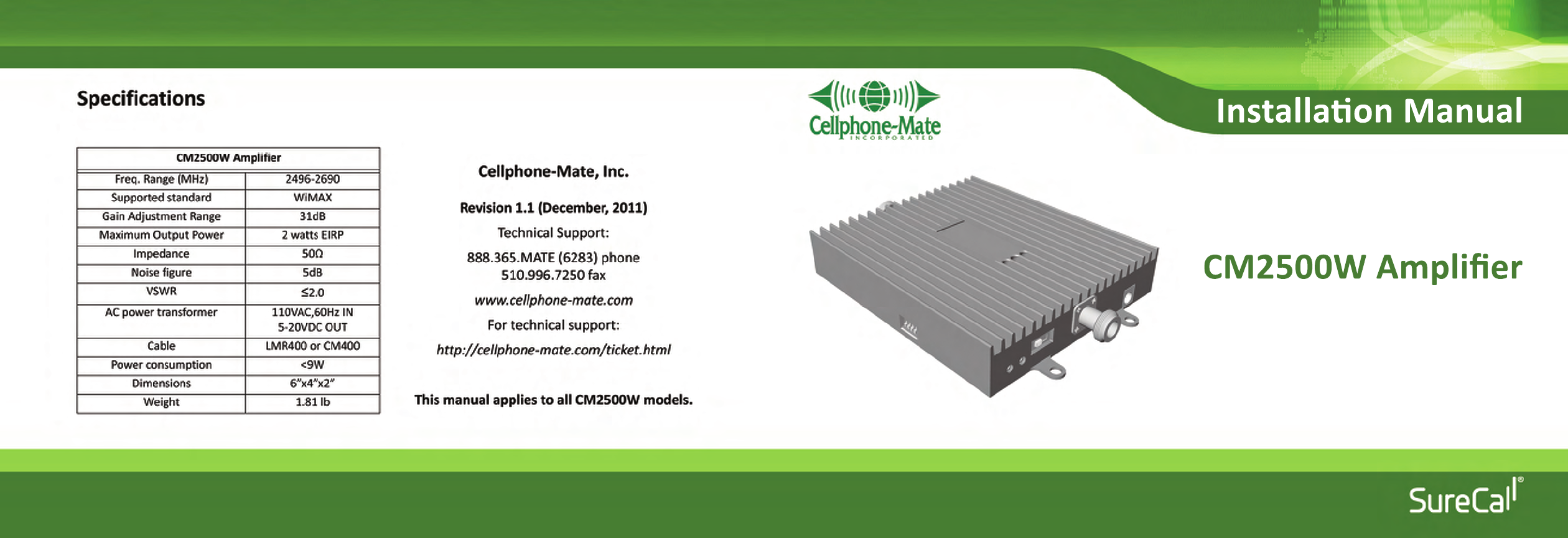
Installaon Manual
CM2500W Amplifier

Copyright 2011 Cellphone-Mate, Inc. All rights reserved. i
CHAPTER 1: Introduction - - - - - - - - - - - - - - - 1
1.1 - Package Contents - - - - - - - - - - - - - - - - 1
1.2 - Features & Benefits - - - - - - - - - - - - - - - 2
1.3 - Additional Items Needed - - - - - - - - - - - 2
1.4 - How It Works - - - - - - - - - - - - - - - - - - - 3
1.5 - About This Manual - - - - - - - - - - - - - - - 3
CHAPTER 2: Safety - - - - - - - - - - - - - - - - - - - - 5
2.1 - Safety Warnings 5 - - - - - - - - - - - - - - - - -
CHAPTER 3: Planning - - - - - - - - - - - - - - - - - - 7
3.1 - Overview - - - - - - - - - - - - - - - - - - - - - - 7
3.2 - Exterior Antenna - - - - - - - - - - - - - - - - - 8
3.3 - Interior Antennas - - - - - - - - - - - - - - - - 9
3.4 - Antenna Separation - - - - - - - - - - - - - 10
3.5 - Calculating Signal Strength - - - - - - - - 13
3.6 - Amplifier Location - - - - - - - - - - - - - - - 14
3.7 - Accessories - - - - - - - - - - - - - - - - - - - - 15
3.8 - Need Help? - - - - - - - - - - - - - - - - - - - - 16
CHAPTER 4: Installation - - - - - - - - - - - - - - - - 17
4.1 - Selecting the Locations - - - - - - - - - - -17
4.2 - Soft Installation - - - - - - - - - - - - - - - - -17
4.3 - Exterior Antenna - - - - - - - - - - - - - - - -17
4.4 - Internal Antennas - - - - - - - - - - - - - - - 18
4.5 - Mounting the Amplifier - - - - - - - - - - - 19
CHAPTER 5: Configuration & Testing - - - - - - 21
5.1 - DIP Switches and Lights - - - - - - - - - - -21
5.2 - Initial Configuration - - - - - - - - - - - - - -23
5.3 - Powering on the Amplifier - - - - - - - - - 23
5.4 - Testing - - - - - - - - - - - - - - - - - - - - - - - 24
5.5 - Adjusting the Amplifier - - - - - - - - - - - 24
5.6 - Automatic Shutdown - - - - - - - - - - - - - 26
CHAPTER 6: Warranty - - - - - - - - - - - - - - - - - 27
6.1 - Warranty Periods - - - - - - - - - - - - - - - -27
6.2 - Warranty Information - - - - - - - - - - - -28
6.3 - Contact Information - - - - - - - - - - - - -30
CHAPTER 7: Regulatory Information - - - - - - 31
7.1 - FCC Information - - - - - - - - - - - - - - - -31
Table of Contents

CM2500W Amplifier - Installation Manual
ii Copyright 2011 Cellphone-Mate, Inc. All rights reserved.
Copyright & Trademark Information
THIS MANUAL CONTAINS SAFETY, INSTALLATION, CONFIGURATION AND WARRANTY INFORMATION
FOR YOUR CELLPHONE-MATE, INC (CMI) AMPLIFIER. CMI RECOMMENDS THAT YOU SAVE THIS MAN-
UAL IN A READILY ACCESSIBLE LOCATION IN CASE ANY QUESTIONS ARISE ABOUT THIS PRODUCT.
Copyright © 2011 by Cellphone-Mate, Inc. All rights reserved. SureCall is a registered trademark and
Cellphone-Mate is a trademark of Cellphone-Mate, Inc. All other trademarks or registered trademarks
are the property of their respective owners.
Copyright 2011 Cellphone-Mate, Inc. All rights reserved. 1
This chapter introduces the
CM2500W Amplifier and this manual.
Read this entire manual before pro-
ceeding with the installation. This
manual is for all CM2500W models.
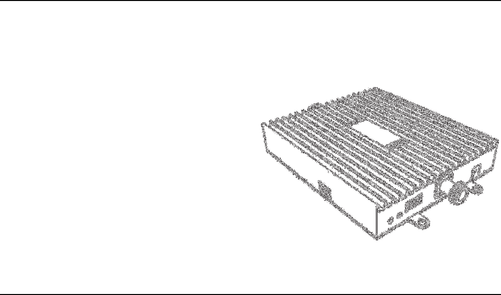
1.1 - Package Contents
Your amplifier box contains the following items:
• CM2500W amplifier.
• Mounting kit (not shown).
• DC power supply (not shown).
• Wall anchors (not shown).
CHAPTER 1: Introduction
CM2500W Amplifier - Installation Manual
2Copyright 2011 Cellphone-Mate, Inc. All rights reserved.
1.2 - Features & Benefits
The CM2500W amplifier offers the following fea-
tures and benefits:
• Powerful in-building amplifier with 31dB of
adjustable gain level.
• Extends cellular signals in areas with poor cov-
erage due to geographical location and/or
building design.
• Suitable for large areas up to about 30,000
square feet depending on outside signal
strength and carrier frequency.
• Sophisticated power control maintains maxi-
mum output power at 2 watts EIRP.
• Automatic oscillation detection and protec-
tion system powers down the amplifier to pre-
vent harmful radio interference (if equipped).
1.3 - Additional Items Needed
The CM2500W amplifier
requires the following
additional components for
a complete installation:
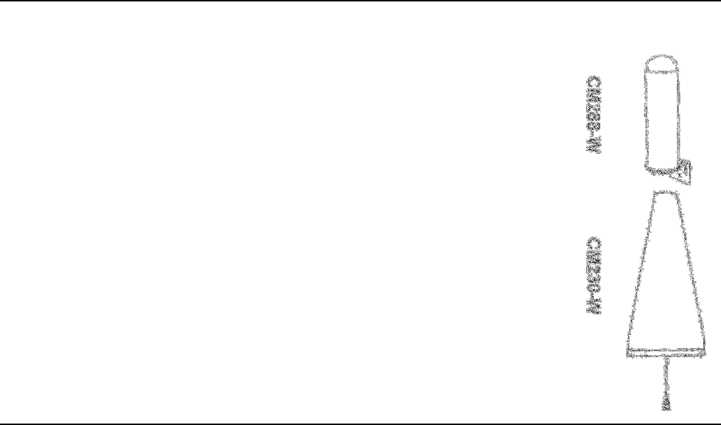
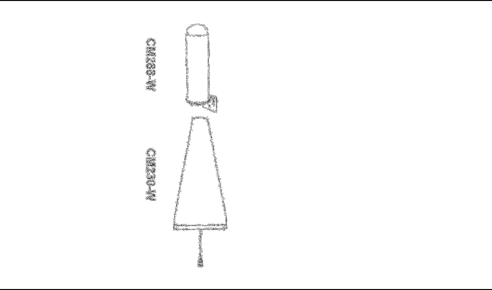
• 4G WiMAX compatible
antenna (such as the
CM288-W omni or
CM230-W Yagi by Cell-
phone-Mate, Inc.)
• Lightning protector
(CMLP).
• Cable splitter if install-
ing multiple antennas
(up to six in a typical
installation).
CHAPTER 1: Introduction
Copyright 2011 Cellphone-Mate, Inc. All rights reserved. 3
• Sufficient CM400 ultra
low loss interior/exte-
rior cable (for amplifi-
ers above 55dB).
• Sufficient CM240 ultra
low loss interior/exte-
rior cable (for amplifi-
ers 55dB and below).
• Up to 6 internal anten-
nas (such as the
CM222-W omnidirec-
tional domes and/or
CM248-W directional
flat panel by Cell-
phone-Mate, Inc.).
• Grounded surge sup-
pressor for DC power
supply.
1.4 - How It Works
The CM2500W amplifier boosts cellular signals
from the nearest cellular tower to phones in a
building and from those phones back to the tower
to compensate for weak reception caused by dis-
tance, topography, building structure, and/or
other reasons. The amplifier receives the signal
from an outside antenna, amplifies that signal,
and then rebroadcasts it via the interior
antenna(s) where it is picked up by cellular
phones, modems, and data cards. The interior
antennas also pick up signals from cellular devices
and pass them to the amplifier. The amplifier
boosts these signals and passes them to the exte-
rior antenna for rebroadcast back to the tower.
1.5 - About This Manual
This manual contains the following information:
CM2500W Amplifier - Installation Manual
4Copyright 2011 Cellphone-Mate, Inc. All rights reserved.
•Introduction: This chapter introduces the
CM2500W amplifier and this manual.
•Safety: This chapter contains important safety
information.
• Planning: This chapter describes how to plan
your installation for best results.
•Installation: This chapter describes how to
install the amplification system.
•Warranty: This chapter contains warranty
information for your amplification system.
•Regulatory Information: This chapter contains
important regulatory agency information.
Lists of items or points to consider that need not
be performed in order appear in bullet format:
• Item 1
• Item 2
Procedures that must be followed in a specific
order appear in numbered steps:
1. Perform this step first.
2. Perform this step second.
This manual also contains important safety infor-
mation and instructions in specially formatted
callouts with accompanying graphic symbols:
WARNING: WARNINGS INDICATE THE
POSSIBILITY OF PERSONAL INJURY.
CAUTION: WARNINGS INDICATE THE
POSSIBILITY OF EQUIPMENT DAMAGE
RADIO INTERFERENCE, ETC.
Note: Notes provide helpful information.
Copyright 2011 Cellphone-Mate, Inc. All rights reserved. 5
This chapter contains important
safety information designed to pre-
vent personal injury, equipment mal-
function, and/or radio interference.
You are responsible for ensuring a
safe installation.
2.1 - Safety Warnings
• You are responsible for knowing and following
all applicable codes and regulations and for
obtaining all required permits and inspections.
• Follow all safety precautions contained in this
Installation Manual.
• The installation process may require working
in high locations such as roofs and/or ladders.
Follow applicable safety regulations and best
practices to avoid falling. Take care not to drop
objects off any high area. Cordon off ground
areas directly below roof or ladder work when
possible.
• Always use appropriate personal protective
equipment such as goggles, gloves, hard hat,
etc. as needed and as required.
WARNING: FAILURE TO EXERCISE CAU-
TION WHEN WORKING IN HIGH AREAS
COULD CAUSE A FALL AND PERSONAL
INJURY.
CHAPTER 2: Safety

CM2500W Amplifier - Installation Manual
6Copyright 2011 Cellphone-Mate, Inc. All rights reserved.
• Some components may be heavy and/or
bulky. Always use proper lifting and carrying
techniques when handling components, espe-
cially when working on a ladder, roof, or other
area with a fall hazard.
• The exterior antenna must not be co-located
or operating in conjunction with any other
antenna.
• Always use a properly installed Cellphone-
Mate lightning protector between the exterior
antenna and the amplifier.
CAUTION: FAILURE TO PROPERLY
INSTALL A LIGHTNING PROTECTOR CAN
RESULT IN DAMAGE TO THE AMPLIFIER,
ANTENNAS, AND WIRING.
• Always power off the amplifier before working
on the roof of the building or anywhere in
close proximity to the external antenna.
• Allow at least 24 inches (60cm) of separation
between interior antennas and humans or ani-
mals.
• Allow at least 24 inches (60cm) of separation
between exterior antennas and all persons.
• Comply with all antenna separation require-
ments to prevent signal oscillation.
CAUTION: SIGNAL OSCILLATION CAN
CAUSE RADIO INTERFERENCE WITH
CELLULAR TOWERS AND RESULT IN
CIVIL AND/OR CRIMINAL PENALTIES.

Copyright 2011 Cellphone-Mate, Inc. All rights reserved. 7
This chapter describes how to plan
your amplifier installation, including
how to determine the best locations
for the inside and outside antennas.
3.1 - Overview
The general amplifier installation process follows
these steps:
1. Decide where to mount the exterior antenna.
This will generally be on the wall or roof of the
building in the location with the strongest sig-
nal. You will need to decide whether to use an
omnidirectional antenna mounted vertically
or a directional Yagi antenna pointed directly
at the cellular tower (line of sight). You must
also consider attaching a grounded lightning
protector between the exterior antenna and
the amplifier.
2. Decide where to mount the interior
antenna(s), being sure to take separation
requirements into account. In general, long
narrow spaces will benefit most from direc-
tional flat-panel antennas while more square
spaces will benefit more from omnidirectional
dome antennas.
3. Decide where to mount the amplifier. This
should be in a secure indoor location near a
grounded power source.
CHAPTER 3: Planning
CM2500W Amplifier - Installation Manual
8Copyright 2011 Cellphone-Mate, Inc. All rights reserved.
4. Decide where to route the cables between the
exterior antenna and the amplifier and
between the amplifier and interior antennas.
5. Install the antennas as described in their
respective Installation Manuals.
6. Route the cables to the amplifier location.
7. Install the amplifier as described in this man-
ual.
8. Power on the amplifier and perform the con-
figuration and testing as described in this
manual.
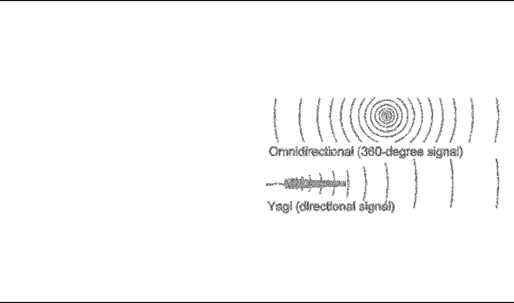
3.2 - Exterior Antenna
You may use either an omnidirectional antenna
such as the CM288-W (flat area with no obstruc-
tions) or a directional Yagi antenna such as the
CM230-W (to point directly at the tower). The
omnidirectional antenna receives and transmits
signals over a horizontal 360-degree circle while
the Yagi antenna receives and transmits signals
over a focused area and must be aimed directly
(line of sight) toward the cellular tower that pro-
vides the best signal to the building.
The exterior antenna and mast (if any) must be
mounted in a location that meets all of the follow-
ing criteria:
• Best signal strength.
CHAPTER 3: Planning
Copyright 2011 Cellphone-Mate, Inc. All rights reserved. 9
• Not collocated with other antennas or used in
conjunction with other antennas.
• Away from all power lines.
• 6’ from lightning rod antennas.
• 24” from all persons.
These distances are general guidelines only; refer
to the applicable building and electrical codes in
your area to determine local requirements.
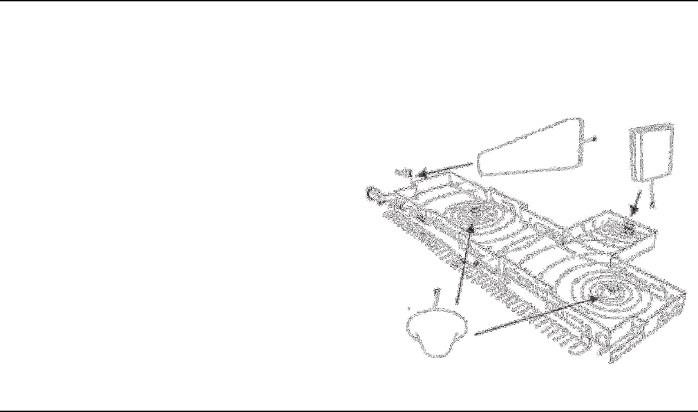
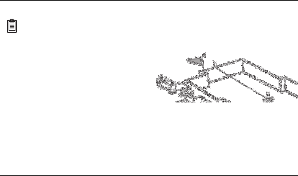
3.3 - Interior Antennas
You may use any combination of omnidirectional
(dome) and/or directional (flat panel) interior
antennas needed to obtain optimal signal
strength throughout the building or installation
area. Dome antennas such as the CM222-W pro-
vide 360-degree hemispherical coverage suitable
for mostly square areas while flat panel antennas
such as the CM248-W provide a focused zone of
coverage suitable for long narrow areas. The fol-
lowing example uses two dome antennas and one
panel antenna to provide full coverage (exterior
Yagi antenna also shown):
CM2500W Amplifier - Installation Manual
10 Copyright 2011 Cellphone-Mate, Inc. All rights reserved.
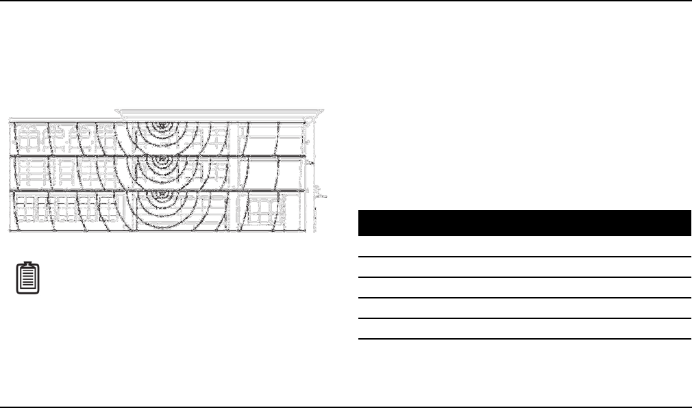
Keep in mind that floor structures in multistory
buildings can cause significant signal loss, which
means that you may need to install interior anten-
nas on more than one floor. Here is an example of
a multistory installation:
Note: You may or may not need anten-
nas on every floor of a multistory build-
ing depending on factors such as
building material, amplifier gain, etc.
3.4 - Antenna Separation
Proper antenna separation is essential in order to
prevent signal oscillation (feedback) that can
interfere with the cellular tower. Separation is
measured in a straight line from the exterior
antenna to the closest interior antenna. The clos-
est allowable distance depends on a number of
factors such as amplifier gain level, building mate-
rial, etc. Recommended separation distances are:
Amplifier gain Min. separation (ad)
40dB 6-7’
45dB 18-25’
50dB 60’
55dB 71’
65dB 88-95’
70dB 117’
CHAPTER 3: Planning
Copyright 2011 Cellphone-Mate, Inc. All rights reserved. 11
The easiest way to calculate the straight-line sepa-
ration between antennas is to break it down into
three simple measurements and then use some
basic geometry to find the distance, as follows:
1. Measure the distances ab, bc, and cd as
shown in the diagram on the next page.
- Distance from the nearest interior antenna
(Point a) to the wall underneath the exte-
rior antenna (Point b). This is distance ab.
Note: Vertical separation is more impor-
tant than horizontal separation. If you
are unable to obtain the required sepa-
ration horizontally, try raising the exte-
rior antenna. You may also try reducing
the amplifier gain as described in Chap-
ter 5 of this manual.
- Distance from Point b to directly under-
neath the exterior antenna. This is Point
(c). This is distance bc.
- Distance from Point c to the exterior
antenna (Point d). This is distance cd.
2. Multiply ab times ab to obtain ab2.
3. Multiply bc times bc to obtain bc2.
4. Multiply cd times cd to obtain cd2.
5. Add ab2+bc2 to obtain ac2.
6. Add ac2+cd2 to obtain ad2.
CM2500W Amplifier - Installation Manual
12 Copyright 2011 Cellphone-Mate, Inc. All rights reserved.
7. The straight-line distance ad is the square root
() of the result obtained in Step 6.
Example:
• Distance ab=40 feet; ab2 = 40x40=1600.
• Distance bc=10 feet; bc2 = 10x10=100.
• Distance cd=20 feet; cd2 = 20x20=400.
•ac2 = 1600+100=1700
•ad2 = 1700+400=2100
•ad = 45.83’
Here, the straight-line distance ad is just under 46
feet, which is compatible with 50dB amplifier gain
as indicated in the previous table.
Note: Most calculators have a square
root () key.
Separate interior antennas based on the calcula-
tions shown in Section 3.5. You may mix and
match dome and directional antennas as needed
to obtain proper coverage throughout the build-
ing or area where you need to boost the signal.
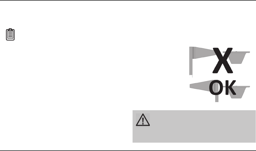
If you are using a
Yagi exterior ant-
enna, you should
normally aim it away
from all interior
antennas regardless
of separation to pre-
vent oscillation.
CAUTION: SIGNAL OSCILLATION CAN
CAUSE RADIO INTERFERENCE WITH
CELLULAR TOWERS AND RESULT IN
CIVIL AND/OR CRIMINAL PENALTIES.

CHAPTER 3: Planning
Copyright 2011 Cellphone-Mate, Inc. All rights reserved. 13
3.5 - Calculating Signal Strength
You can calculate the number of antennas you will
need using the following parameters (in dB):
•Outside signal level (OSL): This is the signal
strength at the exterior antenna location and
will always be a negative number that will usu-
ally fall between -50 and -100dBm. Calls will
drop at levels of about -100dB and lower.
•Outside antenna gain (OAG): This the signal
boost provided by the exterior antenna and is
always a positive number with Cellphone-
Mate antennas.
OAG 2500MHz WiMAX
CM288-W omni +3
CM230-W Yagi +10
•Inside antenna gain (IAG): This is the signal
boost provided by an interior antenna and is
always a positive number with Cellphone-
Mate antennas.
•Cable loss (CL): This is the signal loss caused
by the cable and is always a negative number.
IAG 2500MHz WiMAX
CM222-W omni dome +3
CM248-W directional
panel
+7
CL 2500MHz WiMAX
20’ CM400/CM240 -2.5/-5.0
30’ CM400/CM240 -2.5/-5.0
50’ CM400/CM240 -5.0/-10.0
100’ CM400/CM240 -5.0/-10.0

CM2500W Amplifier - Installation Manual
14 Copyright 2011 Cellphone-Mate, Inc. All rights reserved.
•Splitter loss (SL): This is the signal loss caused
by a splitter (used if you are installing multiple
antennas).
•Amplifier gain (AG): Number of decibels of
amplification provided by the amplifier (rated
gain less any attenuation, as described in
Chapter 5 of this manual). This is always a pos-
itive number.
The signal strength S at an interior antenna equals
OSL+OAG+IAG+CL+SL+AG. To calculate the
approximate coverage distance of each antenna:
1. Calculate the signal strength S for the first
interior antenna using the preceding formula.
SL 2500MHz WiMAX
2-way -3
3-way -5
4-way -6
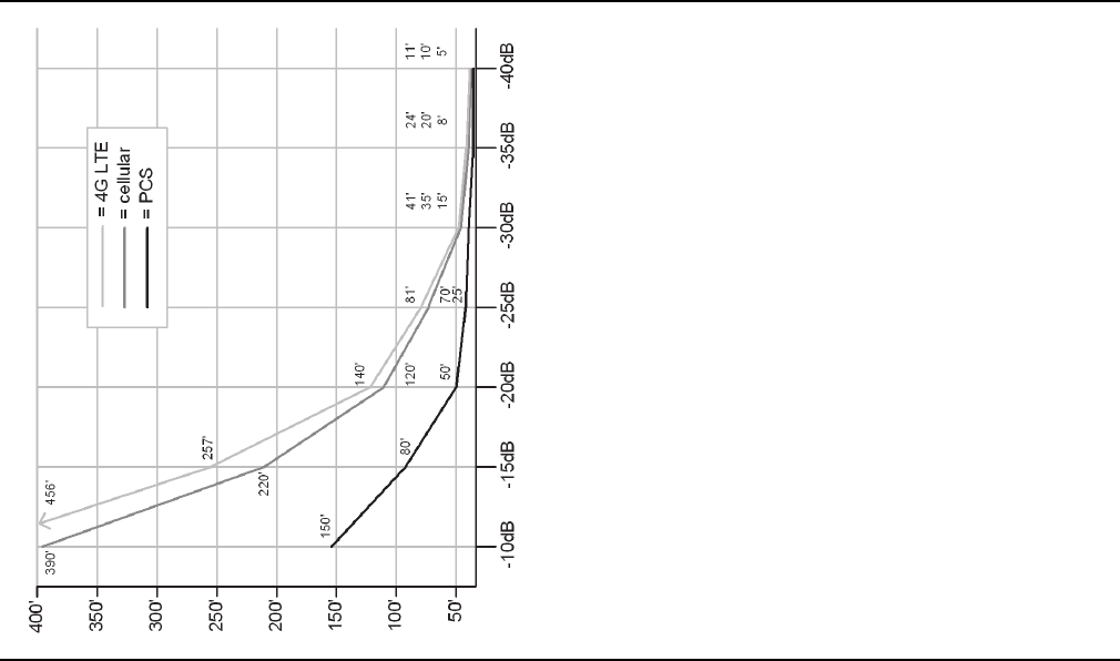
2. Find the signal strength S for the antenna
along the bottom of the graph on the follow-
ing page.
3. Move straight up the signal strength line to
the PCS and cellular curves.
4. Read the approximate coverage radius on the
left.
3.6 - Amplifier Location
Select an indoor location for the amplifier that
meets the following criteria:
• Wall or ceiling mounts are acceptable.
• Near a properly grounded 110VAC outlet.
• Not in a tightly enclosed or overly hot space.
• All power and warning lights easily visible.
• Least amount of cable to connect all antennas.
CHAPTER 3: Planning
Copyright 2011 Cellphone-Mate, Inc. All rights reserved. 15
3.7 - Accessories
The final step in the planning process is to make
sure you have all of the necessary accessories to
complete the installation. You will need all of the
items listed in Chapter 1 of this manual plus some
or all of the following:
•Cable clips: Use these to secure the cables to
interior and exterior walls/ceilings.
•Appropriately rated sealant/caulking: Use
this to waterproof the opening where the
cable from the exterior antenna enters the
building, if needed.
•Hand and/or power tools: As needed to com-
plete the installation.

CM2500W Amplifier - Installation Manual
16 Copyright 2011 Cellphone-Mate, Inc. All rights reserved.
•Personal Protective Equipment (PPE): Use all
PPE required by local codes and/or best prac-
tices to help ensure personal safety during
installation.
Note: You may need to obtain a permit
from your local building department to
install the amplifier and antennas.
Check your local building and/or electri-
cal codes. You do not need any permits
from the FCC or the cellular carrier.
CAUTION: YOU ARE RESPONSIBLE FOR
ENSURING THAT THE INSTALLATION
MEETS ALL APPLICABLE CODES.
3.8 - Need Help?
If you need help planning your installation, please
contact a qualified installer, the reseller from
whom you purchased the amplifier, or Cellphone-
Mate, Inc.

Copyright 2011 Cellphone-Mate, Inc. All rights reserved. 17
This chapter describes how to install
the amplifier and antennas for best
results.
4.1 - Selecting the Locations
Select the locations for the exterior antenna, inte-
rior antenna(s), amplifier, cables, and accessories
as described in the previous chapter.
CAUTION: FAILURE TO PROPERLY PLAN
THE AMPLIFIER INSTALLATION CAN
CAUSE SIGNAL OSCILLATION AND/OR
OTHER EQUIPMENT MALFUNCTION.
4.2 - Soft Installation
Perform a “soft” installation of all components to
test signal coverage and oscillation before making
the installation permanent. Avoid making holes or
other permanent fixtures during this initial phase.
Please refer to Chapter 5 of this manual for config-
uration and testing instructions. Proceed with the
final installation once configuration and testing
are complete.
4.3 - Exterior Antenna
Mount the exterior antenna in the location you
selected during the planning process. Be sure to
follow all of the instructions included with the
antenna to ensure a safe installation. Remember:
CHAPTER 4: Installation
CM2500W Amplifier - Installation Manual
18 Copyright 2011 Cellphone-Mate, Inc. All rights reserved.
• An omnidirectional antenna (CM288-W) must
be mounted vertically.
• A Yagi antenna (such as the CM230-W) must
be mounted horizontally and be aimed at the
desired cellular tower (line of sight).
CAUTION: MOUNT THE EXTERIOR
ANTENNA ON A FIXED STRUCTURE .
WARNING: FAILURE TO EXERCISE CAU-
TION WHEN WORKING IN HIGH AREAS
COULD CAUSE A FALL AND PERSONAL
INJURY.
WARNING: DO NOT TOUCH ANY LIVE
ELECTRICAL WIRES OR ALLOW THE
ANTENNA OR CABLING TO TOUCH ANY
LIVE ELECTRICAL WIRES.
1. Mount the antenna.
2. Connect a length of CM400 cable to the
antenna and tighten until hand-tight.
3. Run the cable along the planned route.
4. Install a properly grounded CMLP lightning
protector.
5. Seal any holes you make in the outside of the
building with appropriate caulking or sealant.
4.4 - Internal Antennas
Mount the interior antenna(s) in the location(s)
you selected during the planning process. Be sure
CAUTION: AVOID AIMING A YAGI
ANTENNA TOWARD ANY INTERIOR
ANTENNA .
CHAPTER 4: Installation
Copyright 2011 Cellphone-Mate, Inc. All rights reserved. 19
to follow the instructions included with the
antenna(s) for a safe installation. Remember:
• Dome antennas (CM222-W, etc.) should be
mounted in the ceiling as close to the center
of the desired coverage area as possible with
the domed side pointing down.
• Flat panel antennas (CM248-W) should be
wall-mounted as close as possible to center of
the wall at one end of long narrow space.
1. Mount the antenna.
CAUTION: VERIFY THAT ALL INTERIOR
ANTENNAS MEET THE SEPARATION
REQUIREMENTS DESCRIBED IN THE
PREVIOUS CHAPTER AND THAT NO
ANTENNA IS AIMED TOWARD THE
EXTERIOR ANTENNA .
2. Connect a length of CM400 or CM240 cable to
the antenna and tighten until hand-tight.
3. If you are installing multiple antennas, run the
cable to the splitter location and connect the
cable to one of the outputs on the splitter.
4. Connect another length of CM400 or CM240
cable to the input side of the splitter (if used)
and run this cable to the amplifier location.
4.5 - Mounting the Amplifier
Mount the amplifier as follows:
1. Verify that the selected location meets all of
the criteria described in the previous chapter.
CAUTION: DO NOT CONNECT AN
INTERIOR ANTENNA TO THE SPLITTER
INPUT.
CM2500W Amplifier - Installation Manual
20 Copyright 2011 Cellphone-Mate, Inc. All rights reserved.
2. Attach the included mounting kit to the ampli-
fier using the screws provided. Tighten the
screws by hand with a screwdriver until snug
plus 1/4 to 1/2 turn. Do not over-tighten.
3. Mount the amplifier to the wall using appro-
priate screws and/or wall anchors. The top
side of the amplifier with the lights and DIP
switches should be facing up and be plainly
visible when standing near the amplifier.
4. Connect the exterior antenna cable to the
Outside Antenna port on the amplifier.
5. Connect the interior antenna cable to the
Inside Antenna port on the amplifier.
6. Verify that all cable connections are snug and
that the exterior and interior antennas are
connected to the proper jacks.
CAUTION: DO NOT POWER ON THE
AMPLIFIER UNTIL INSTRUCTED TO DO
SO.
CAUTION: NEVER POWER ON THE
AMPLIFIER WHEN ANY ANTENNAS ARE
DISCONNECTED AS THIS COULD DAM-
AGE THE AMPLIFIER.
Copyright 2011 Cellphone-Mate, Inc. All rights reserved. 21
This chapter describes how to power
on, configure, and test the amplifier.
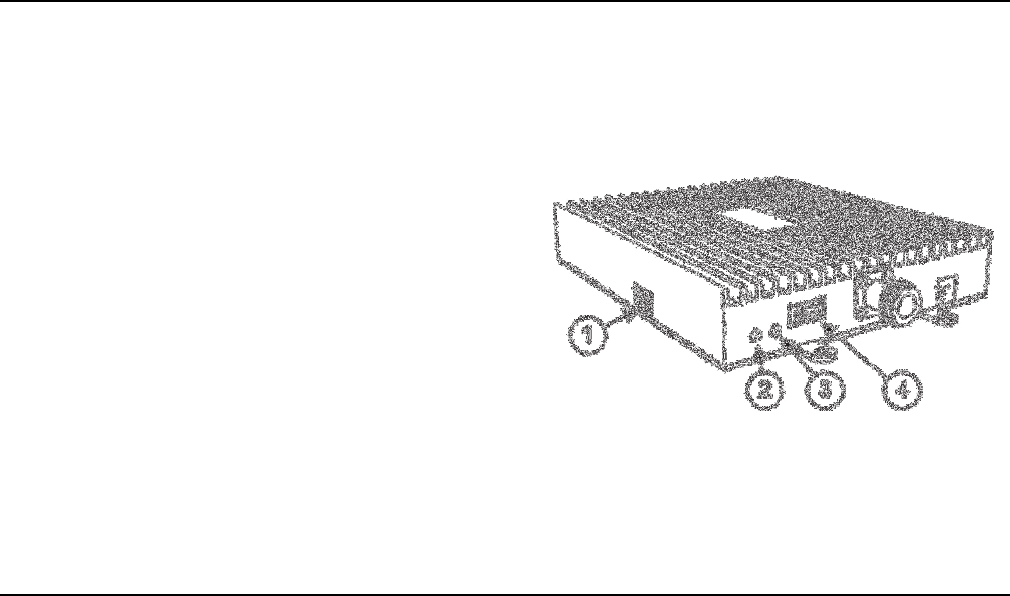
5.1 - DIP Switches and Lights
The CM2500W amplifier has the following indica-
tors and controls:
• Gain DIP switches (1): These DIP switches con-
trol the amplification gain.
• Warning light (2): This light illuminates when
signal oscillation is occurring.
• Power light (3): This light should always be
illuminated or blinking green while the ampli-
fier is powered on.
• Power switch (4): Allows you to turn the
amplifier on and off.
When the amplifier is plugged in and powered on:
• The green Power light (3) should illuminate.
CHAPTER 5: Configuration & Testing
CM2500W Amplifier - Installation Manual
22 Copyright 2011 Cellphone-Mate, Inc. All rights reserved.
• The red Warning light (2) should remain OFF.
If the Warning light illuminates, power off the
amplifier immediately.
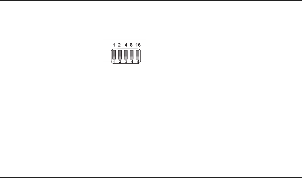
The bank of DIP switches on the
side of the amplifier contains five
switches.
• Moving a switch down
(toward from the base of the amplifier) turns
that switch OFF and increases amplifier gain
for the selected channel.
• Moving a switch up (away from the base of
the amplifier) turns that switch ON and
decreases amplifier gain for the selected chan-
nel.
From left to right, the DIP switches provide 1, 2, 4,
8, and 16 dB of attenuation (reduced amplifica-
tion). These switches are cumulative, meaning
that the total amount of attenuation for a channel
is equal to the combined dB of all ON DIP
switches. For example:
• Turning all switches OFF = 0dB attenuation
(amplifier is at full gain).
• Turning ON Switch #1 = 1dB attenuation
(amplifier maximum gain is reduced by 1dB).
• Turning ON Switches #1, 3, and 5 = 1+4+16dB
attenuation = 21dB attenuation. For example,
in a 70dB amplifier, this means that the
selected channel would be reduced to 49dB
(70db-21db).
• Turning ON all switches = 1+2+4+8+16dB
attenuation = 31dB attenuation. For example,
in a 70dB amplifier, that means that the
selected channel would be reduced to 39dB
(70dB-31dB).
CHAPTER 5: Configuration & Testing
Copyright 2011 Cellphone-Mate, Inc. All rights reserved. 23
5.2 - Initial Configuration
By default, your amplifier ships with all DIP
switches turned OFF to provide maximum gain in
all channels. This should always be your starting
point whenever installing or reinstalling the
amplifier.
5.3 - Powering on the Amplifier
To power on the amplifier:
1. Make sure both antenna cables are snugly
connected to the proper amplifier ports.
2. Plug a surge suppressor into a grounded
110VAC wall outlet.
3. Plug the AC end of the power adapter that
came with the amplifier into the surge sup-
pressor.
4. Plug the DC end of the power adapter into the
Power port on the amplifier
5. Power on the amplifier using the Power
switch.
6. Verify that the green Power light is illumi-
nated.
7. If the red Warning light illuminates, immedi-
ately power off the amplifier by either unplug-
ging the DC power supply from the surge
suppressor or by turning off the switch on the
surge suppressor. Increase the attenuation
CAUTION: ONLY USE THE POWER SUP-
PLY INCLUDED WITH THE AMPLIFIER.
USE OF ANOTHER POWER SUPPLY
COULD DAMAGE THE AMPLIFIER AND/
OR POWER SUPPLY.

CM2500W Amplifier - Installation Manual
24 Copyright 2011 Cellphone-Mate, Inc. All rights reserved.
(reduce gain). If you are at maximum attenua-
tion and still receiving a warning, then you
must verify that all antennas have been placed
according to these instructions and relocate
antennas as needed to eliminate the oscilla-
tion. See Section 5.6 for more information.
8. Once the amplifier is powered on and the red
Warning light is not illuminated, you may pro-
ceed to adjust the amplifier.
CAUTION: DO NOT PROCEED BEYOND
THIS POINT UNTIL THE AMPLIFIER IS
POWERED ON AND NO RED WARNING
LIGHTS ARE ILLUMINATED.
5.4 - Testing
Once the amplifier is powered on and the Warn-
ing light is not illuminated, walk around the entire
area to test the voice and/or data signal. Refine
the antenna locations and/or gain levels as
needed, and then complete the permanent instal-
lation once the system is working as desired.
5.5 - Adjusting the Amplifier
Keep the following points in mind when adjusting
the amplifier:
• Full gain is not always your best option. Your
goal is to obtain a usable cellular signal in as
many areas of the building as possible. A suc-
cessful installation means that you can make
calls without dropping and/or have a reliable
data connection.

CHAPTER 5: Configuration & Testing
Copyright 2011 Cellphone-Mate, Inc. All rights reserved. 25
• Do not expect to see 5 bars of reception
everywhere in the building as this is practically
impossible. Also, signal strength in dB can vary
significantly without necessarily affecting the
number of bars displayed because different
phone and data card manufacturers handle
bars sightly differently.
• A good rule of thumb is that increasing gain by
6dB doubles the coverage distance of the inte-
rior antennas. Start at the lowest gain setting
and increase gain gradually as needed.
• If the red Warning light comes on, oscillation
is either happening or is about to happen and
protection circuits are activating (if equipped).
If oscillation is or becomes severe, the ampli-
fier will power down and will then wake every
30 seconds for the next 15 minutes to see if
the problem has been resolved. If the problem
has not been resolved after 15 minutes, the
amplifier will shut off and will need to be
unplugged and plugged back in again to reset.
• If you can’t get the system to work properly,
you may need to install an additional interior
antenna and/or a different type of interior
antenna and/or relocate interior antennas.

CM2500W Amplifier - Installation Manual
26 Copyright 2011 Cellphone-Mate, Inc. All rights reserved.
5.6 - Automatic Shutdown
If equipped, the CM2500W amplifier includes an
automatic shutdown feature that works in the fol-
lowing sequence:
1. When oscillation is detected in the uplink and/
or downlink, the Warning light will begin
flashing red and the Power light will turn red.
2. If the problem is not resolved, the amplifier
will shut down after 30 seconds.
3. The amplifier will wake back up. When this
occurs, the Power light will be green. If oscilla-
tion resumes, the lights will flash as previously
described. These 30-second cycles will con-
tinue for 15 minutes or until the problem is
resolved.
4. If the problem is not resolved within 15 min-
utes, the amplifier will shut down (all lights off
except the Power light, which is red) and must
be reset by unplugging it from the power sup-
ply and plugging it back in.
To resolve oscillation, increase the antenna sepa-
ration (Section 3.4) and/or the attenuation (Sec-
tion 5.1).

Copyright 2011 Cellphone-Mate, Inc. All rights reserved. 27
This chapter contains the warranty
information for your CELLPHONE-
MATE product and also contains
information on how to contact the
company.
6.1 - Warranty Periods
Your warranty includes the following periods:
•Two-Year Product Warranty: CELLPHONE-
MATE products are covered under a two-year
product warranty from the date of purchase.
This protects the customer from any defects
or problems the product may have that are
solely the fault of CELLPHONE-MATE Inc.
Incorrect installation or misuse will void this
warranty. Upon the return of a defective prod-
uct, CELLPHONE-MATE will issue the customer
a working replacement. All returned packages
should contain all products distributed.
•Five-Year Extended Product Warranty: A five
year warranty is available for purchase on any
products sold by CELLPHONE-MATE Inc. A five-
year warranty must be obtained at the time of
purchase. This warranty adds an additional
three years to the two year warranty we pro-
vide. All regulations still apply.
CHAPTER 6: Warranty

CM2500W Amplifier - Installation Manual
28 Copyright 2011 Cellphone-Mate, Inc. All rights reserved.
6.2 - Warranty Information
1. CELLPHONE-MATE, Inc. warrants to the Buyer
that each of its products will be free from
defects in material and workmanship and will
perform in full accordance with applicable
specifications when shipped. The limit of lia-
bility under this warranty is, at CELLPHONE-
MATE, Inc.’s option, to repair or replace any
product or part thereof which shall, within
TWO YEARS of purchase as determined by
examination by CELLPHONE-MATE, Inc., prove
defective in material and/or workmanship.
Warranty returns must first be authorized in
writing by CELLPHONE-MATE, Inc. Disassembly
of any CELLPHONE-MATE, Inc. product by any-
one other than an authorized representative
of CELLPHONE-MATE, Inc. voids this warranty
in its entirety. CELLPHONE-MATE, Inc. reserves
the right to make changes in any of its prod-
ucts without incurring any obligation to make
the same changes on previously delivered
products.
2. As a condition of the warranties provided for
herein, the Buyer will prepay the shipping
charges for all products returned to CELL-
PHONE-MATE, Inc. for repair and CELLPHONE-
MATE, Inc. will pay the return shipping with
the exception of product returned from out-
side the United States, in which case the Buyer
will pay all shipping charges.
3. The Buyer will pay the cost of inspecting and
testing any goods returned under the war-
ranty or otherwise which are found to meet
the applicable specifications or which are not
defective or not covered by this warranty.
4. Products sold by CELLPHONE-MATE, Inc. shall
not be considered defective or non-conform-

CHAPTER 6: Warranty
Copyright 2011 Cellphone-Mate, Inc. All rights reserved. 29
ing to the Buyer’s order if they satisfactorily
fulfill the performance requirements that
were published in the product specification lit-
erature, or in accordance with samples pro-
vided by CELLPHONE-MATE, Inc. This warranty
shall not apply to any products or parts
thereof which have been subject to accident,
negligence, alteration, abuse, or misuse. CELL-
PHONE-MATE, Inc. makes no warranty what-
soever in respect to accessories or parts not
supplied by it.
5. Limitations of Warranty, Damages and Liabil-
ity: EXCEPT AS EXPRESSLY SET FORTH HEREIN,
THERE ARE NO WARRANTIES, CONDITIONS,
GUARANTEES OR REPRESENTATIONS AS TO
MERCHANTABILITY, FITNESS FOR A PARTICU-
LAR PURPOSE OR OTHER WARRANTIES, CON-
DITIONS, GUARANTEES OR
REPRESENTATIONS, WHETHER EXPRESSED OR
IMPLIED, IN LAW OR IN FACT, ORAL OR IN
WRITING. CELLPHONE-MATE, INC.’S AGGRE-
GATE LIABILITY IN DAMAGES OR OTHERWISE
SHALL NOT EXCEED THE PAYMENT, IF ANY,
RECEIVED BY CELLPHONE-MATE, INC. FOR THE
UNIT OF PRODUCT OR SERVICE FURNISHED
OR TO BE FURNISHED, AS THE CASE MAY BE,
WHICH IS THE SUBJECT OF CLAIM OR DIS-
PUTE. IN NO EVENT SHALL CELLPHONE-MATE,
INC. BE LIABLE FOR INCIDENTAL, CONSEQUEN-
TIAL, OR SPECIAL DAMAGES, HOWSOEVER
CAUSED.
6. All matters regarding this warranty shall be
interpreted in accordance with the laws of the
State of California and any controversy that
cannot be settled directly shall be settled by
arbitration in California in accordance with the
rules then prevailing of the American Arbitra-
tion Association, and judgment upon the

CM2500W Amplifier - Installation Manual
30 Copyright 2011 Cellphone-Mate, Inc. All rights reserved.
award rendered may be entered in any court
having jurisdiction thereof.
7. If one or more provisions provided herein are
held to be invalid or unenforceable under
applicable law, then such provision shall be
ineffective and excluded to the extent of such
invalidity or unenforceability without affecting
in any way the remaining provisions herein.
8. CELLPHONE-MATE reserves the right to bill for
labor spent on equipment where there is no
defective found
9. All items that are out of warranty are subject
to a repair fee and additional freight charges.
10. Defective items in warranty will be repaired at
no additional charge and will be returned with
freight paid by CELLPHONE-MATE.
6.3 - Contact Information
You may consult a Cellphone-Mate, Inc. customer
service agent directly by contacting us as follows:
• View the list of Frequently Asked Questions
(FAQ) online at http://cellphone-mate.com/
tech_faq.html.
• Our online support center is at http://cell-
phone-mate.com/ticket.html. If needed, you
can create an online support ticket. This is the
fastest and best way to get support for your
product.
• Write to the address at the web site or call the
phone number on the back cover of this man-
ual.

Copyright 2011 Cellphone-Mate, Inc. All rights reserved. 31
This chapter contains the regulatory
information for the FCC (USA).
7.1 - FCC Information
FCC ID: RSNCM2500W
Warning: Changes or modifications to this device
not expressly approved by Cellphone-Mate, Inc.
could void the user’s authority to operate the
equipment.
Note: This equipment has been tested and found
to comply with the limits pursuant to Part 27 of
the FCC Rules. These limits are designed to pro-
vide reasonable protection against harmful inter-
ference in a residential installation. This
equipment generates, uses, and can radiate radio
frequency energy and, if not installed and used in
accordance with the instructions, may cause
harmful interference to radio communications.
However, there is no guarantee that interference
will not occur in a particular installation. If the
equipment does cause harmful interference to
radio or television reception, which can be deter-
mined by turning the equipment off and on, the
user is encouraged to try to correct the interfer-
ence by one or more of the following measures:
• Reorient or relocate the receiving antenna.
• Increase the separation between the equip-
ment and receiver.
CHAPTER 7: Regulatory Information

CM2500W Amplifier - Installation Manual
32 Copyright 2011 Cellphone-Mate, Inc. All rights reserved.
• Connect the equipment to an outlet on a cir-
cuit different from that to which the receiver
is connected.
• Consult the dealer or an experienced radio/TV
technician for help.
This equipment complies with FCC radiation expo-
sure limits set forth for an uncontrolled environ-
ment. This transmitter must not be co-located or
operating in conjunction with any other antenna
or transmitter. In accordance with FCC require-
ments of human exposure to radio frequency
fields, the radiating element (antenna) shall be
installed such that a minimum separation distance
of 60cm (24in) is maintained from all persons.

Chapter 7: Regulatory Information
33
Copyright 2011 Cellphone-Mate, Inc. All rights reserved.
This page intentionally left blank.

CM2500W Amplifier - Installation Manual
34 Copyright 2011 Cellphone-Mate, Inc. All rights reserved.
This page intentionally left blank.