Cellphone Mate SureCall FORCE-5 Five Band In Building linear Signal Booster User Manual Force 5 User Guide
Cellphone-Mate Inc. dba SureCall Five Band In Building linear Signal Booster Force 5 User Guide
Contents
- 1. Users Manual
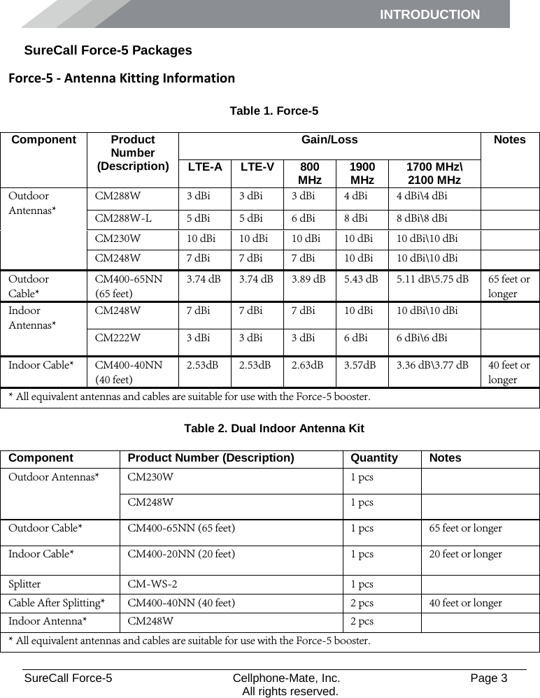
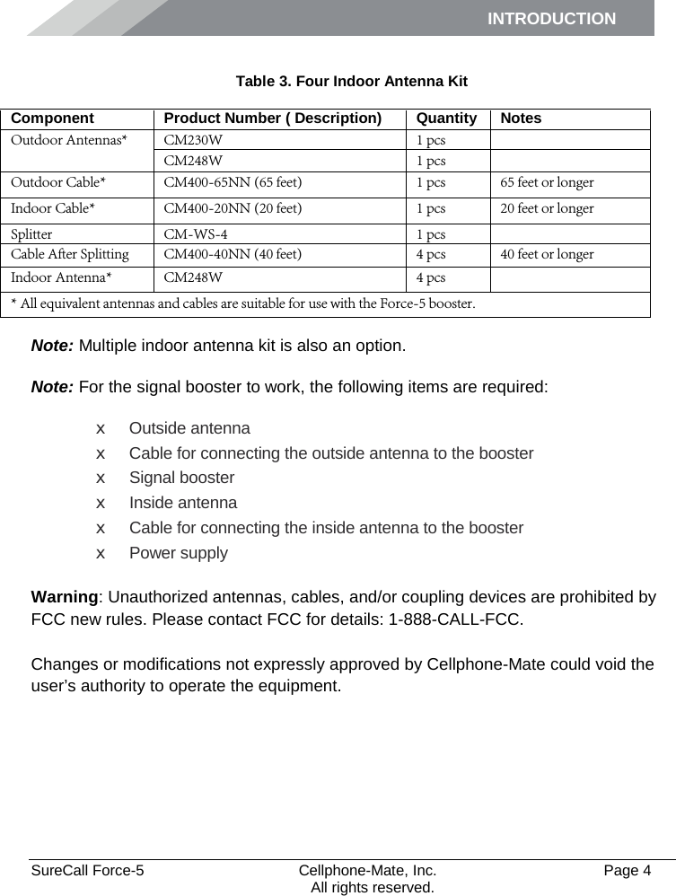
- 2. Antenna Kitting Info
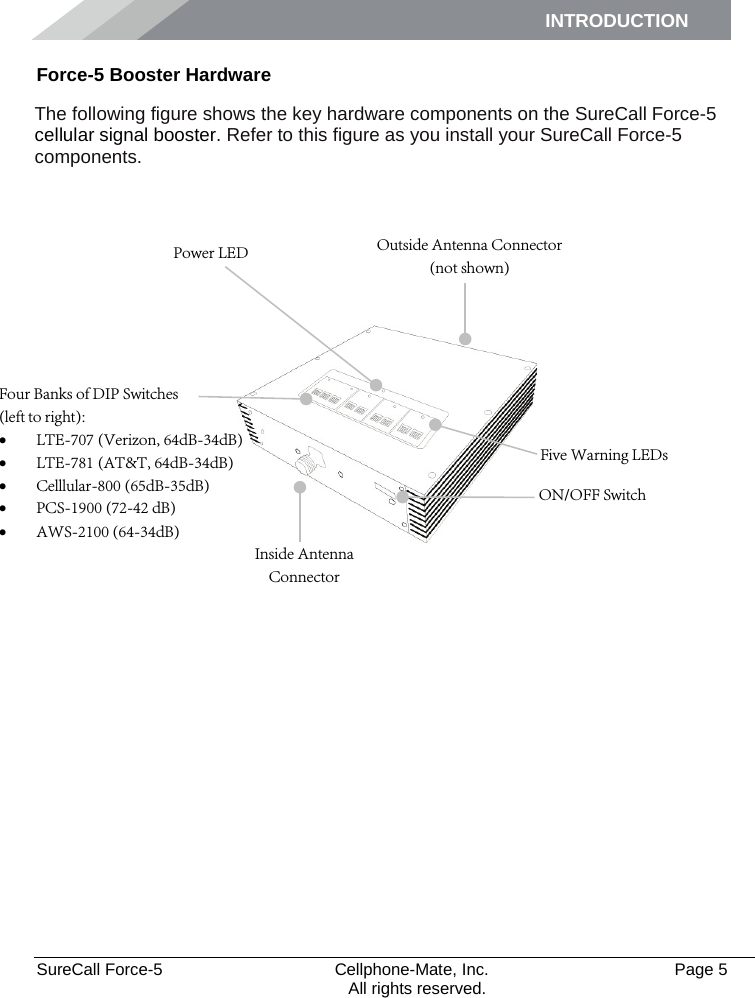
Users Manual