Cellphone Mate SureCall FORCE-5 Five Band In Building linear Signal Booster User Manual Force 5 User Guide
Cellphone-Mate Inc. dba SureCall Five Band In Building linear Signal Booster Force 5 User Guide
Contents
- 1. Users Manual
- 2. Antenna Kitting Info
Users Manual
Five-Band Wireless
Adjustable Signal Booster / Kit
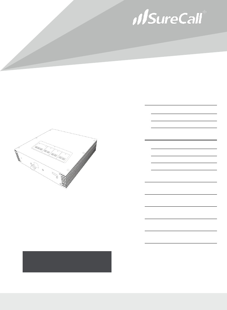
Force-5™ Booster, Force-5
Omni Kit, Force-5 Panel Kits
(FORCE-5)
User Guide
INTRODUCTION
2
THEORY OF OPERATION 2
SURECALL FORCE-5 PACKAGES 3
FORCE-5 BOOSTER HARDWARE 5
INSTALLATION
6
SITE SELECTION 6
INSTALLATION INSTRUCTIONS 7
LEDS 12
AUTOMATIC SHUTDOWN 13
TROUBLESHOOTING
14
FREQUENTLY ASKED QUE
STIONS 16
OBTAINING TECHNICAL
SUPPORT 16
WARRANTY
17
SPECIFICATIONS
19
SAFETY INFORMATION
20

INTRODUCTION
SureCall Force-5 Cellphone-Mate, Inc. Page 2
All rights reserved.
Introduction
Congratulations on purchasing the SureCall Force-5, the finest cellular signal
booster available!
SureCall adjustable cellular signal boosters and kits from Cellphone-Mate remove
frustrations over dropped calls, limited range, and slow data rates by amplifying incoming
and outgoing cellular signals in buildings, offices, and homes. The Force-5 is designed
with leading-edge technologies to detect and amplify weak incoming signals your cellular
device would otherwise miss and to broadcast a significantly stronger signal back to the
cell tower.
This guide contains all the information you need to get your SureCall Force-5 booster
system up and running.
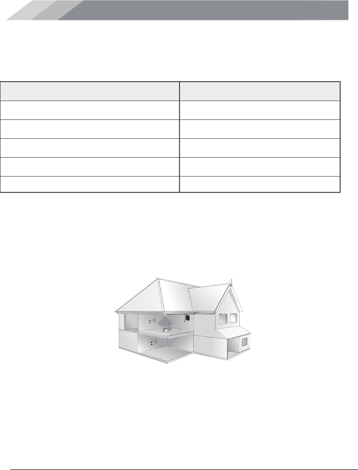
Theory of Operation
The SureCall Force-5 is a high-quality bidirectional signal booster that boosts cellular
signals for areas prone to weak or shadowed cellular coverage.
The Force-5 works with two antennas
:
x An inside antenna that communicates with your cell phone.
x An outside antenna that communicates with the cell tower.
Signals sent from a cell tower are received by the outside antenna, amplified by the
booster and then sent to your phone via the inside antenna.
When your phone transmits, the signal is sent to the inside antenna, and then sent to
the cell tower via the outside antenna.
Some cell signal is required for the Force-5 to enhance cellular signal coverage. The
weakest cell signal for the Force-5 to work is low -100dBm to high -90dBm. dBm is an
abbreviation for the power ratio in decibels of the radio power per one milliwatt.
To measure your existing cell signal on an Apple iPhone, dial *3001#12345#*and
press Call. In the top-left corner, a number appears instead of bars.
For Android devices, you can download several apps to measure exact signal
strength. Look up check real signal strength to find a cell signal measurement app.
INTRODUCTION
SureCall Force-5 Cellphone-Mate, Inc. Page 3
All rights reserved.
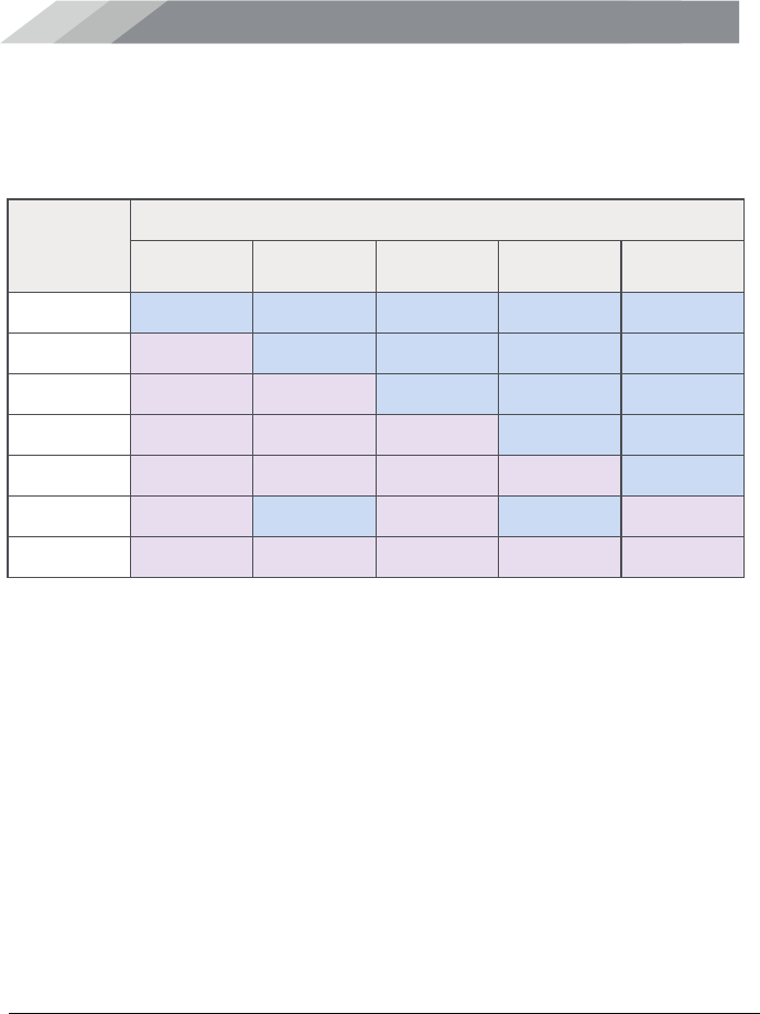
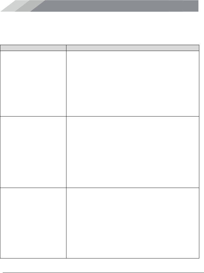
SureCall Force-5 Packages
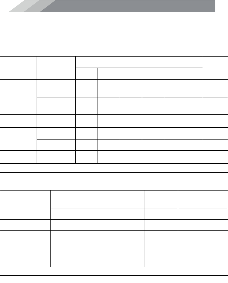
Force-5 - Antenna Kitting Information
Table 1. Force-5
Component
Product
Number
(Description)
Gain/Loss
Notes
LTE-A
LTE-V
800
MHz
1900
MHz
1700 MHz\
2100 MHz
Outdoor
Antennas*
CM288W
3 dBi
3 dBi
3 dBi
4 dBi
4 dBi\4 dBi
CM288W-L 5 dBi 5 dBi 6 dBi 8 dBi 8 dBi\8 dBi
CM230W 10 dBi 10 dBi 10 dBi 10 dBi 10 dBi\10 dBi
CM248W 7 dBi 7 dBi 7 dBi 10 dBi 10 dBi\10 dBi
Outdoor
Cable*
CM400-
65NN
(65 feet)
3.74 dB 3.74 dB 3.89 dB 5.43 dB 5.11 dB\5.75 dB 65 feet or
longer
Indoor
Antennas*
CM248W 7 dBi 7 dBi 7 dBi 10 dBi 10 dBi\10 dBi
CM222W 3 dBi 3 dBi 3 dBi 6 dBi 6 dBi\6 dBi
Indoor Cable*
CM400-40NN
(40 feet)
2.53dB
2.53dB
2.63dB
3.57dB
3.36 dB\3.77 dB
40 feet or
longer
* All equivalent antennas and cables are suitable for use with the Force-5 booster.
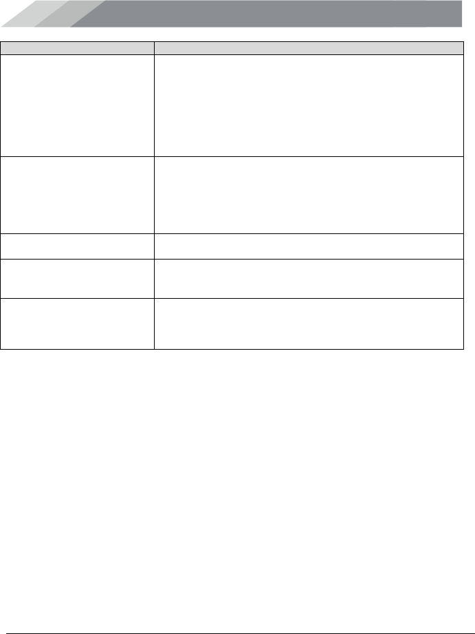
Table 2. Dual Indoor Antenna Kit
Component
Product Number (Description)
Quantity
Notes
Outdoor Antennas* CM230W 1 pcs
CM248W 1 pcs
Outdoor Cable* CM400-65NN (65 feet) 1 pcs 65 feet or longer
Indoor Cable* CM400-20NN (20 feet) 1 pcs 20 feet or longer
Splitter
CM-WS-2
1 pcs
Cable After Splitting* CM400-40NN (40 feet) 2 pcs 40 feet or longer
Indoor Antenna* CM248W 2 pcs
* All equivalent antennas and cables are suitable for use with the Force-5 booster.
INTRODUCTION
SureCall Force-5 Cellphone-Mate, Inc. Page 4
All rights reserved.
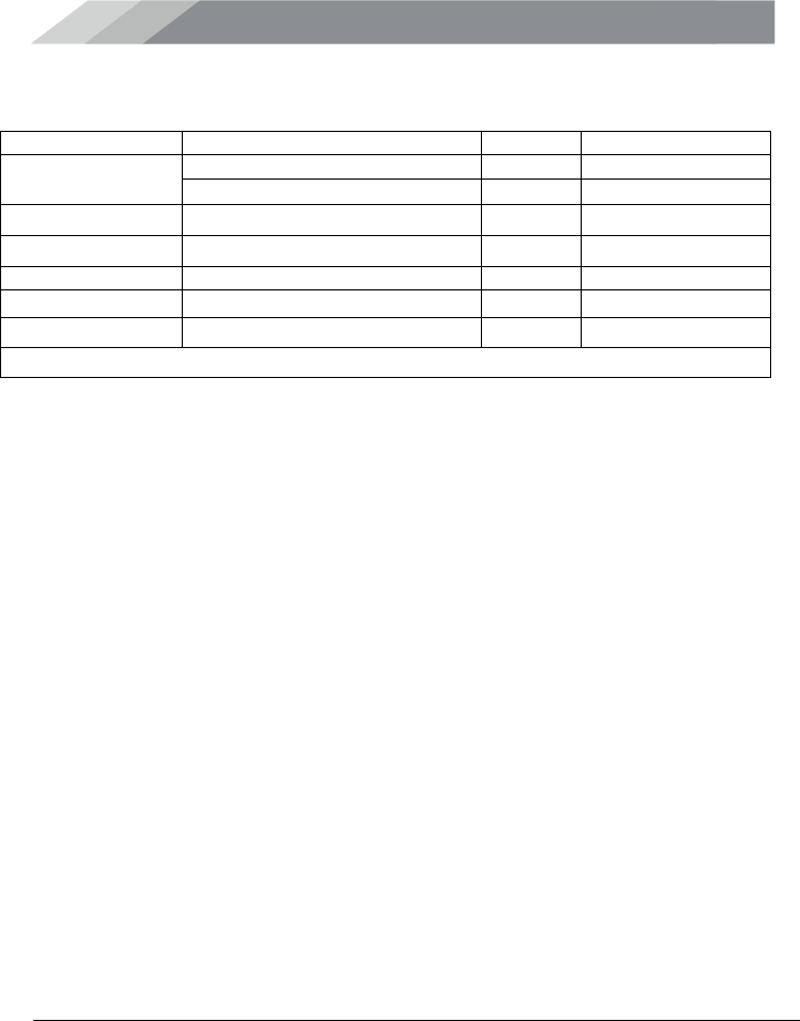
Table 3. Four Indoor Antenna Kit
Component
Product Number ( Description)
Quantity
Notes
Outdoor Antennas*
CM230W
1 pcs
CM248W 1 pcs
Outdoor Cable*
CM400-65NN (65 feet)
1 pcs
65 feet or longer
Indoor Cable*
CM400-20NN (20 feet)
1 pcs
20 feet or longer
Splitter
CM-WS-4
1 pcs
Cable After Splitting CM400-40NN (40 feet) 4 pcs 40 feet or longer
Indoor Antenna*
CM248W
4 pcs
* All equivalent antennas and cables are suitable for use with the Force-5 booster.
Note: Multiple indoor antenna kit is also an option.
Note: For the signal booster to work, the following items are required:
x Outside antenna
x Cable for connecting the outside antenna to the booster
x Signal booster
x Inside antenna
x Cable for connecting the inside antenna to the booster
x Power supply
Warning: Unauthorized antennas, cables, and/or coupling devices are prohibited by
FCC new rules. Please contact FCC for details: 1-888-CALL-FCC.
Changes or modifications not expressly approved by Cellphone-Mate could void the
user’s authority to operate the equipment.
INTRODUCTION
SureCall Force-5 Cellphone-Mate, Inc. Page 5
All rights reserved.
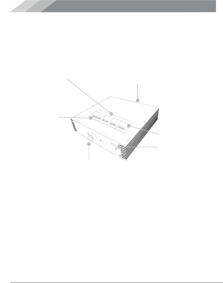
Force-5 Booster Hardware
The following figure shows the key hardware components on the SureCall Force-5
cellular signal booster. Refer to this figure as you install your SureCall Force-5
components.
Five Warning LEDs
Outside Antenna Connector
(not shown)
Inside Antenna
Connector
Four Banks of DIP Switches
(left to
right):
•
LTE-707 (Verizon, 64dB-34dB)
•
LTE-781 (AT&T, 64dB-34dB)
•
Celllular-800 (65dB-35dB)
•
PCS-1900 (72-42 dB)
•
AWS-2100 (64-34dB)
Power LED
ON/OFF Switch

INSTALLATION
SureCall Force-5 Cellphone-Mate, Inc. Page 6
All rights reserved.
Installation
Unpack all package contents and check for damage. For missing or damaged
items, contact your reseller. Keep the carton and packing material to store the
product or if you need to return it.
Site Selection
For optimum performance, select a location for your booster that
:
x Provides the best signal strength possible. To measure your existing cell
signal on an Apple iPhone, dial *3001#12345#*and press Call. In the top-
left corner, a number appears instead of bars. For Android devices, you
can download several apps to measure exact signal strength. Look up
“check real signal strength“ to find a cell signal measurement app.
x Avoids areas where wireless signals can be blocked or reflected by
buildings, walls, trees, hills, and other terrain features. This can result in
low signal strength.
x Is not close to energy-efficient windows, which can affect signal
penetration into a home or off
ic
e.
Note: The cell phone tower site in relation to the location where you install your
booster also determines signal strength. Although cell phone providers try to pla
c
e
towers for maximum coverage, local ordinances and terrain features can restr
ic
t
tower locations, which can limit signal strength at your lo
c
ation.

INSTALLATION
SureCall Force-5 Cellphone-Mate, Inc. Page 7
All rights reserved.
Installation Instructions
The Force-5 signal booster is suited for installation in a building or home.
Step 1. Connect the Outside Antenna
1. Mount the fiberglass antenna in an outside mounting location that:
x Has at least a 12-inch radius clear of obstructions and other radiating
elements.
x Is at least 75 feet in a straight line from the inside antenna when used in
an area prone to weak cellular signals and operating the booster at full 65
dB gain.
x Is not co-located or operating with any other antenna or booster.
FCC 27.50(d)(4) Statement: Fixed, mobile, and portable (hand-held) stations
operating in the 1710 – 1755 MHz band are limited 1 Watt EIRP. Fixed stations
operating in this band are limited to a maximum antenna height of 10 meters above
ground. Mobile and portable stations operating in this band must employ a means for
limiting power to the minimum necessary for successful communications.
2. Using the CM400 cable, connect the outside antenna to the booster connector
marked OUTSIDE (see page 5).
3. Hand tighten the connection.
Step 2. Connect the Inside Antenna
1. Mount the inside antenna:
x Omnidirectional dome antenna: mount the antenna on the ceiling in a
central location where you want reception.
x Panel antenna: install the antenna
INSTALLATION
SureCall Force-5 Cellphone-Mate, Inc. Page 8
All rights reserved.
IMPORTANT: A minimum separation distance of 30 vertical feet is necessary
between the outside and inside antennas. If the inside coverage is not sufficient, you
may need as much as 80 feet of separation. See the following table.
x Use directional flat-panel antennas for long, narrow spaces. Mount them
as close as possible to the center of the wall at one end of long narrow
space.
x Use omnidirectional dome antennas for square spaces favorable to using
a central antenna. Mount them in the ceiling, as close to the center of the
desired coverage area as possible, with the domed side pointing down
2. Using the CM400 cable, connect the inside antenna to the booster connector
marked INSIDE (see page 5).
3. Hand tighten the connection.
To Use This Much Booster Gain...
Allow This Much Separation...
40 dB
5 – 10 feet
45 dB
15 – 20 feet
50 dB
50 - 55 feet
55 dB
55 – 65 feet
65 dB
70 – 80 feet

INSTALLATION
SureCall Force-5 Cellphone-Mate, Inc. Page 9
All rights reserved.
Step 3. Mount the Booster (Optional)
1. Select a location for your booster.
2. Attach the supplied mounting kit to the booster using the supplied screws.
Tighten the screws with a screwdriver until snug, then add a ¼-to-1/2 turn. Do
not over tighten.
3. Orient the signal booster so the LEDs and DIP switches face away from the
wall and the LEDs are seen easily. Then mount the signal booster to the wall
using appropriate screws and/or wall anchors.
4. Connect the outdoor antenna cable to the Outdoor Antenna port on the
booster.
5. Connect the indoor antenna cable to the Indoor Antenna port on the booster.
6. Verify that all cable connections are snug, and that the outdoor and indoor
antennas are connected to the proper jacks.
Step 4. Connect to AC Power
1. Connect the AC power cord to the booster (see page 5).
2. Connect the plug on the other end to a 110V AC power outlet. Be sure all
connections to the booster are tight and secure.
x The booster turns on automatically.
x The Power LED goes ON to show that the booster is ready for use (see
page 5).
x The Alert LEDs flash up to 15 seconds on each band to show the band is
activated (see page 5).
The booster is rated for 5-20V input voltage. DO NOT use the booster with a
higher voltage power supply. This can damage the booster and/or cause
personal injury.
INSTALLATION
SureCall Force-5 Cellphone-Mate, Inc. Page 10
All rights reserved.
Step 5. Configure Switch Settings
Facing the front of your booster, find 4 banks of dual in-line package (DIP) switches
(see page 5). These switches let you attenuate the dB gain manually for uplink and
downlink channels.
x Bank 1 controls LTE amplification in the building:
o The switches marked LTE 707 control uplink amplification for
Verizon.
o The switches marked LTE-781 control uplink amplification for
AT&T.
o The switches between LTE 707 and LTE-781 control downlink
amplification for both Verizon and AT&T.
x Bank 2 controls Cellular amplification in the building.
x Bank 3 controls PCS amplification in the building.
x Bank 4 controls AWS amplification in the building.
The DIP switches in each bank correspond to the following dB gain values:
Switch 1
Switch 2
Switch 3
Switch 4
Switch 5
1 dB
2 dB
4 dB
8 dB
16 dB
For maximum gain on all channels, your booster ships with all DIP switches turned
ON. This setting should always be your starting point when installing or reinstalling
the booster. To change it, move the DIP switches to the ON or OFF position.
x Moving a switch down (away from the LEDs) turns OFF the switch and
increases booster gain for the selected channel.
x Moving a switch up (toward the LEDs) turns ON the switch and
decreases booster gain for the selected channel.
INSTALLATION
SureCall Force-5 Cellphone-Mate, Inc. Page 11
All rights reserved.
Switch settings are cumulative. This means the total amount of attenuation for a
channel equals the combined dB of all DIP switches in the same bank being set to
ON.
Tip: The Force-5 signal booster comes unattenuated or fully powered. If you cannot
obtain sufficient antenna separation, use the DIP switches to attenuate the booster’s
dB gain.
To
Achieve...
Set the DIP Switches in the Same Bank as Follows...
SW1
(1 dB)
SW2
(2 dB)
SW3
(4 dB)
SW4
(8 dB)
SW5
(16 dB)
0 DB
OFF
OFF
OFF
OFF
OFF
1 DB
ON
OFF
OFF
OFF
OFF
3 dB
ON
ON
OFF
OFF
OFF
7 dB
ON
ON
ON
OFF
OFF
15 dB
ON
ON
ON
ON
OFF
21 dB
ON
OFF
ON
OFF
ON
31 dB
ON
ON
ON
ON
ON
INSTALLATION
SureCall Force-5 Cellphone-Mate, Inc. Page 12
All rights reserved.
LEDs
The top panel of the signal booster has a Power light-emitting diode (LED), along
with the following warning LEDs (see page 5):
x LTE-707
x LTE-781
x Cellular-800
x PCS-1900
x AWS-2100
LED
Designation
Description
LTE-707
LTE 707 Uplink
OFF = normal operation.
ON = LTE 707 uplink warning (Verizon). Power off
booster immediately.
LTE-781
LTE 781 Uplink
OFF = normal operation.
ON = LTE 781 uplink warning (AT&T). Power off
booster immediately.
Cellular-800
Cellular Uplink
OFF = normal operation.
ON = cellular uplink warning. Power off booster
immediately.
PCS-1900
PCS Uplink
OFF = normal operation.
ON = PCS uplink warning. Power off booster
immediately.
AWS-2100
AWS Uplink
OFF = normal operation.
ON = AWS uplink warning. Power off booster
immediately.
Power
Power
Green ON or blink = booster is receiving power.
OFF = booster is not receiving power.
Red ON = oscillation has occurred for longer than
15 minutes and the booster is shutting down (see
Automatic Shutdown on page 13).

INSTALLATION
SureCall Force-5 Cellphone-Mate, Inc. Page 13
All rights reserved.
Automatic Shutdown
SureCall boosters that have automatic shutdown work in the following way:
1. The cellular LEDs are usually the first side to experience oscillation. When
oscillation is detected in the uplink and/or downlink, the appropriate red
Warning LEDs flash and Power turns red.
2. If oscillation occurs on the LTE, Cellular, PCS, or AWS side, the respective
LED blinks as appropriate and Power turns red due to cellular oscillation.
3. If the problem is not resolved, the affected side shuts down after 30 seconds.
In general, the cellular side oscillates more easily than the PCS side.
4. The booster wakes up and Power (LED 3) turns green. If oscillation resumes,
the LEDs flash as described previously. These 30-second cycles continue for
15 minutes or until the problem is resolved.
5. If the problem is not resolved within 15 minutes, the booster shuts down
automatically (all LEDs OFF except Power, which is red) and must be reset by
unplugging the booster from the power supply and plugging it back in.
6. To resolve oscillation, increase antenna separation and/or the attenuation (see
the table on page 8).
TROUBLESHOOTING
SureCall Force-5 Cellphone-Mate, Inc. Page 14
All rights reserved.
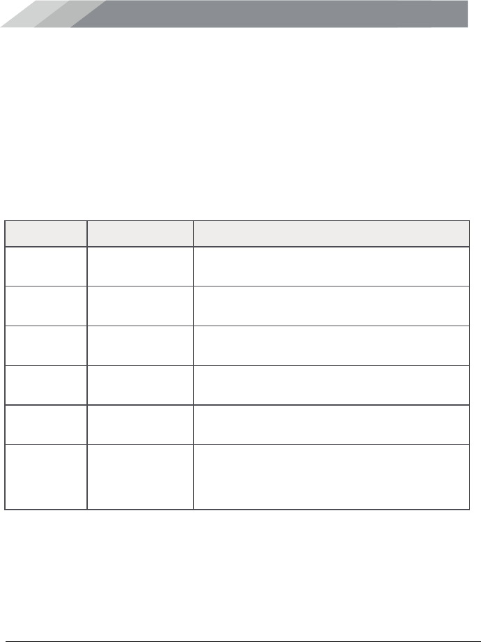
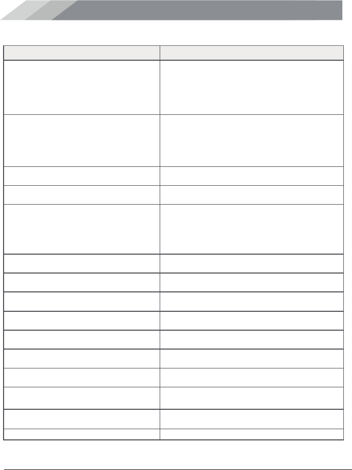
Troubleshooting
In the unlikely event you encounter a problem, use the following steps to identify and
resolve the issue.
Problem
Resolution
Booster has no power.
1. Verify that the switch on the power supply is turned on
and red LED is ON.
2. Connect the power supply to an alternate power
source.
3. Be sure the power source is not controlled by a switch
that can remove power from the outlet.
4. Check the green POWER LED on the booster. If it is
OFF, return the power supply to Cellphone-Mate.
Contact tech support at 1-888-365-6283, email
support@surecall.com, or go to surecall.com and log
on via online support to receive a Return Merchandise
Authorization (RMA).
After installing the
booster system, you
have no signal or
reception.
1. Check the strength of the outside signal as close as
you can to the outside antenna. To measure your
existing cell signal:
Apple iPhone: dial *3001#12345#*and press Call. In
the top-left corner, a number replaces the bars.
Android devices: download apps to measure exact
signal strength, such as Network Signal Info in the
Google Play store. Search "check real signal strength"
to find other cell signal measurement apps.
2. Double-check all booster and antenna cable
connections.
3. Be sure your booster's dB gain is turned up to full
power on each switch.
One of the red lights next
to the switches on your
booster is flashing.
1. Turn down the dB gain on the switch until the light goes
OFF or turns yellow.
2. Be sure the inside panel antenna is facing away from
the outside antenna.
3. Use the recommended antenna separation:
• 65dB 60 ft. separation
• 63dB 50-60 ft. separation
• 55dB 40-50 ft. separation
• 50dB 30-40 ft. separation
• 45dB 20-30 ft. separation
• 40dB 10-20 ft. separation
• 35dB 10 ft. separation
TROUBLESHOOTING
SureCall Force-5 Cellphone-Mate, Inc. Page 15
All rights reserved.
Problem
Resolution
Your booster restarted
and shut down for 15
minutes, and is now shut
down permanently.
Each SureCall booster is equipped with Auto Shutdown
to prevent cell tower interference. The outside antenna
may be close to a cell tower. Move the outside antenna to
a location that provides sufficient distance from the cell
tower to prevent the booster from automatically enabling
Auto Shutdown. Once away from the original location,
perform the procedure under Step 4. Connect to AC
Power on page 9.
The red LED goes ON.
More antenna separation is needed. If you cannot
provide more antenna separation and the Alert LEDs
flash after the initial activation period, lower the switch
below the blinking LED by 5 dB (for example, from 50 to
45) and monitor the bars on your cell phone to see
whether reception improves.
The Power LED does not
turn ON.
Be sure the AC outlet is working and is not controlled by
a wall switch that can remove power from the outlet.
The Alert LEDs flash
after the initial activation
period.
Lower the switch below the blinking LED by 5 dB (for
example, from 60 to 55) and monitor the bars on your cell
phone to see whether reception has improved.
The Alert LEDs continue
to flash.
The booster shuts down automatically, and then restarts
after 60 seconds. Turn down the switch that is oscillating
(for example, Cellular-800 or PCS-1900) to prevent the
booster from shutting down automatically.

FREQUENTLY ASKED QUESTIONS
SureCall Force-5 Cellphone-Mate, Inc. Page 16
All rights reserved.
Frequently Asked Questions
For a list of Frequently Asked Questions and a comprehensive, up-to-date
Troubleshooting Guide, please visit our website at: www.surecall.com or call us
at 1-800-365-6283.
Obtaining Technical Support
You can also consult a Cellphone-Mate technical specialist directly by emailing us at
support@surecall.com.
Record the model and serial number for your products:
Serial #: ______________________________________________________
Purchase Date: ________________________________________________

WARRANTY
SureCall Force-5 Cellphone-Mate, Inc. Page 17
All rights reserved.
Warranty
Two-Year Product Warranty
Cellphone-Mate warrants its products for two years from the date of purchase against defects in
workmanship and/or materials.
Products returned by customers must be in their original, un-modified condition, shipped in the original or
protective packaging with proof-of-purchase documentation enclosed, and a Return Merchandise
Authorization (RMA) number printed clearly on the outside of the shipping container.
Buyers may obtain an RMA number for warranty returns by calling the Cellphone-Mate Return Department
toll-free at 1-888-365-6283. Any returns received by Cellphone-Mate without an RMA number clearly printed
on the outside of the shipping container will be returned to sender. In order to receive full credit for signal
boosters, all accessories originally included in the signal booster box must be returned with the signal
booster. (The Buyer does not need to include accessories sold in addition to the signal booster, such as
antennas or cables.)
This warranty does not apply to any product determined by Cellphone-Mate to have been subjected to
misuse, abuse, neglect, or mishandling that alters or damages the product’s physical or electronic properties.
Cellphone-Mate warrants to the Buyer that each of its products, when shipped, will be free from defects in
material and workmanship, and will perform in full accordance with applicable specifications. The limit of
liability under this warranty is, at Cellphone-Mate’s option, to repair or replace any product or part thereof
which shall within TWO YEARS of purchase as determined by examination by Cellphone-Mate, prove
defective in material and/or workmanship. Warranty returns must first be authorized in writing by Cellphone-
Mate. Disassembly of any Cellphone-Mate, Inc. product by anyone other than an authorized representative of
Cellphone-Mate voids this warranty in its entirety. Cellphone-Mate reserves the right to make changes in any
of its products without incurring any obligation to make the same changes on previously delivered products.
As a condition to the warranties provided for herein, the Buyer will prepay the shipping charges for all
products returned to Cellphone-Mate for repair, and Cellphone-Mate will pay the return shipping with the
exception of products returned from outside the United States, in which case the Buyer will pay the shipping
charges.
The Buyer will pay the cost of inspecting and testing any goods returned under the warranty or otherwise,
which are found to meet the applicable specifications or which are not defective or not covered by this
warranty.
Products sold by Cellphone-Mate shall not be considered defective or non-conforming to the Buyer’s order if
they satisfactorily fulfill the performance requirements that were published in the product specification
literature, or in accordance with samples provided by Cellphone-Mate. This warranty shall not apply to any
products or parts thereof which have been subject to accident, negligence, alteration, abuse, or misuse.
Cellphone-Mate makes no warranty whatsoever in respect to accessories or parts not supplied by it.

WARRANTY
SureCall Force-5 Cellphone-Mate, Inc. Page 18
All rights reserved.
Limitations of Warranty, Damages and Liability:
EXCEPT AS EXPRESSLY SET FORTH HEREIN, THERE ARE NO WARRANTIES, CONDITIONS,
GUARANTEES, OR REPRESENTATIONS AS TO MERCHANTABILITY, FITNESS FOR A PARTICULAR
PURPOSE, OR OTHER WARRANTIES, CONDITIONS, GUARANTEES, OR REPRESENTATIONS,
WHETHER EXPRESSED OR IMPLIED, IN LAW OR IN FACT, ORAL OR IN WRITING.
CELLPHONE-MATE AGGREGATE LIABILITY IN DAMAGES OR OTHERWISE SHALL NOT EXCEED THE
PAYMENT, IF ANY, RECEIVED BY CELLPHONE-MATE, INC. FOR THE UNIT OF PRODUCT OR
SERVICE FURNISHED OR TO BE FURNISHED, AS THE CASE MAY BE, WHICH IS THE SUBJECT OF
CLAIM OR DISPUTE. IN NO EVENT SHALL CELLPHONE-MATE, INC. BE LIABLE FOR INCIDENTAL,
CONSEQUENTIAL, OR SPECIAL DAMAGES, HOWSOEVER CAUSED.
All matters regarding this warranty shall be interpreted in accordance with the laws of the State of California,
and any controversy that cannot be settled directly shall be settled by arbitration in California in accordance
with the rules then prevailing of the American Arbitration Association, and judgment upon the award rendered
may be entered in any court having jurisdiction thereof.
If one or more provisions provided herein are held to be invalid or unenforceable under applicable law, then
such provision shall be ineffective and excluded to the extent of such invalidity or unenforceability without
affecting in any way the remaining provisions hereof.
SPECIFICATIONS
SureCall Force-5 Cellphone-Mate, Inc. Page 19
All rights reserved.
Specifications
Specification
FORCE–5
Uplink Frequency Range:
Cellular–800:
PCS:
LTE–A:
LTE–V:
AWS:
824 – 849 MHz
1850 – 1910 MHz
698 – 716 MHz
776 – 787 MHz
1710 – 1755 MHz
Downlink Frequency Range:
Cellular–800:
PCS:
LTE–A:
LTE–V:
AWS:
869 – 894 MHz
1930 – 1990 MHz
728 – 746 MHz
746 – 757 MHz
2110 – 2155 MHz
Supported Standards:
CDMA, GSM, LTE
Input/Output Impedance:
50 Ω
Maximum Gain:
Cellular–800:
PCS:
LTE–A:
LTE–V:
AWS:
65 dB
72
dB
63.5
dB
64.3
dB
71
dB
Noise Figure:
8 dB
VSWR:
≤2.0
AC Power Transmitter:
Input AC 110 V, 60 Hz
Output: DC 19 V
Maximum Output Power:
1 Watt EIRP
Cable:
CM400 recommended
RF Connectors:
N Female, both ends
Power Consumption:
<50W
Dimensions:
11.3 x 10.9 x 3.5 in.
(28.6 x 27.6 x 8.84 cm.)
Weight:
16.5 lbs.
(7.48 kgs.)
FCC ID (USA):
RSNFORCE–5
SAFETY INFORMATION
SureCall Force-5 Cellphone-Mate, Inc. Page 20
All rights reserved.
Safety Information
Note: This equipment has been tested and found to comply with the limits for a Class B digital
device, pursuant to part 15 of the FCC Rules. These limits are designed to provide reasonable
protection against harmful interference in a residential installation. This equipment generates, uses
and can radiate radio frequency energy and, if not installed and used in accordance with the
instructions, may cause harmful interference to radio communications. However, there is no
guarantee that interference will not occur in a particular installation. If this equipment does cause
harmful interference to radio or television reception, which can be determined by turning the
equipment off and on, the user is encouraged to try to correct the interference by one or more of
the following measures:
x Reorient or relocate the receiving antenna.
x Increase the separation between the equipment and receiver.
x Connect the equipment into an outlet on a circuit different from that to which the
receiver is connected.
x Consult the dealer or an experienced radio/TV technician for help.

SureCall Force-5 Cellphone-Mate, Inc. Page 21
All rights reserved.
48346 Milmont Drive
Fremont, California 94538
USA
888.365.6283
Fax: 510.996.7250
www.surecall.com
Cellphone-Mate has made a good faith effort to ensure the accuracy of the
information in this document and disclaims the implied warranties of merchantability
and fitness for a particular purpose and makes no express warranties, except as
may be stated in its written agreement with and for its customers.
Cellphone-Mate shall not be held liable to anyone for any indirect, special or
consequential damages due to omissions or errors. The information and
specifications in this document are subject to change without notice.
Copyright © 2014. All Rights Reserved.
All trademarks and registered trademarks are the property of their respective
owners.
Force-5 User Guide
February 10, 2014
(20130228) V1.3??