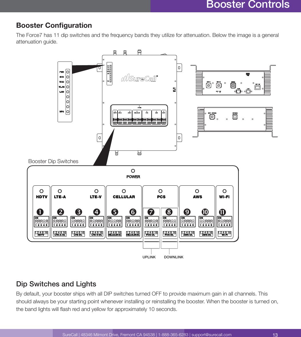
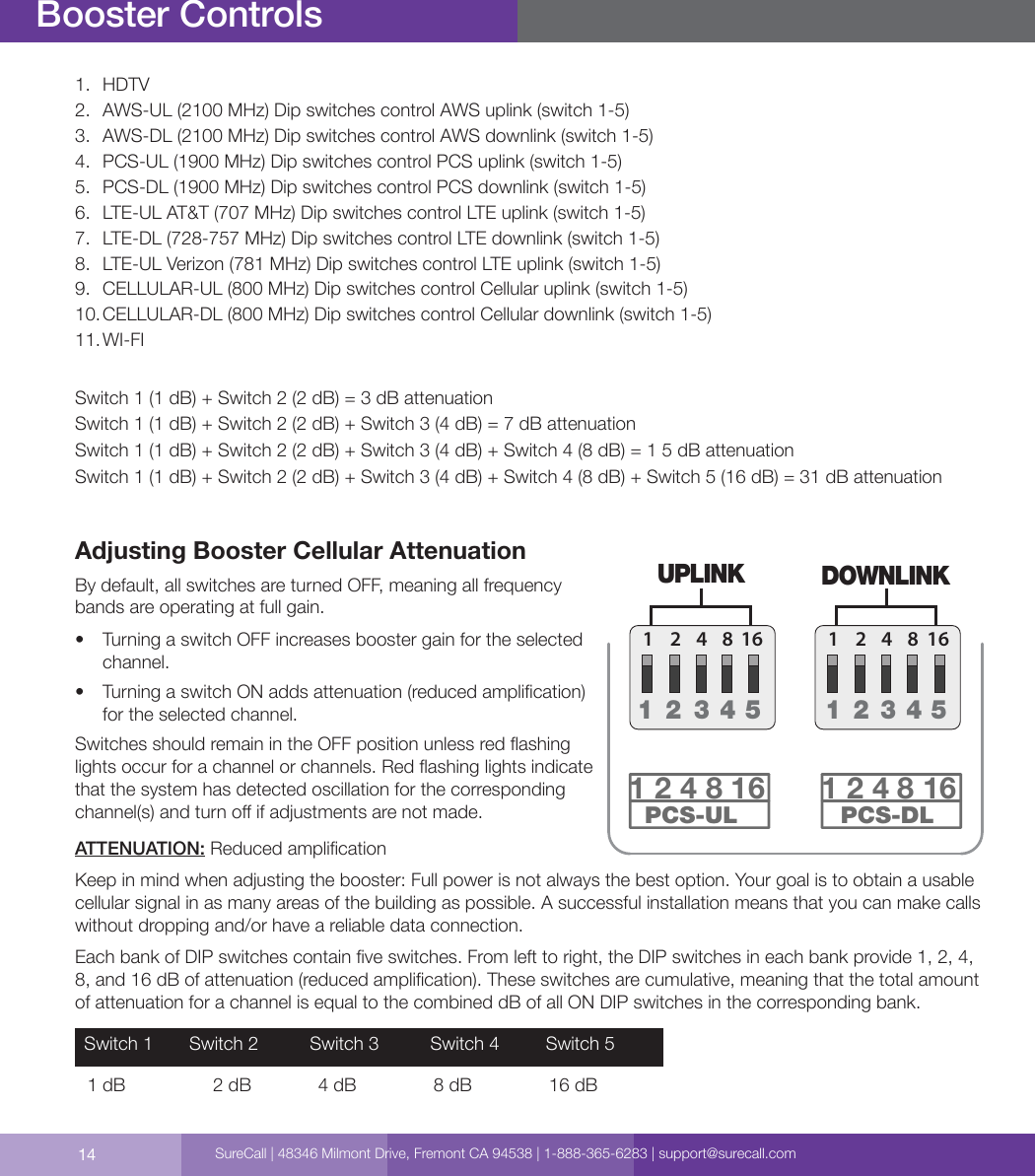
Cellphone Mate SureCall FORCE-7 All in one Cellular, WiFi and HDTV Booster User Manual

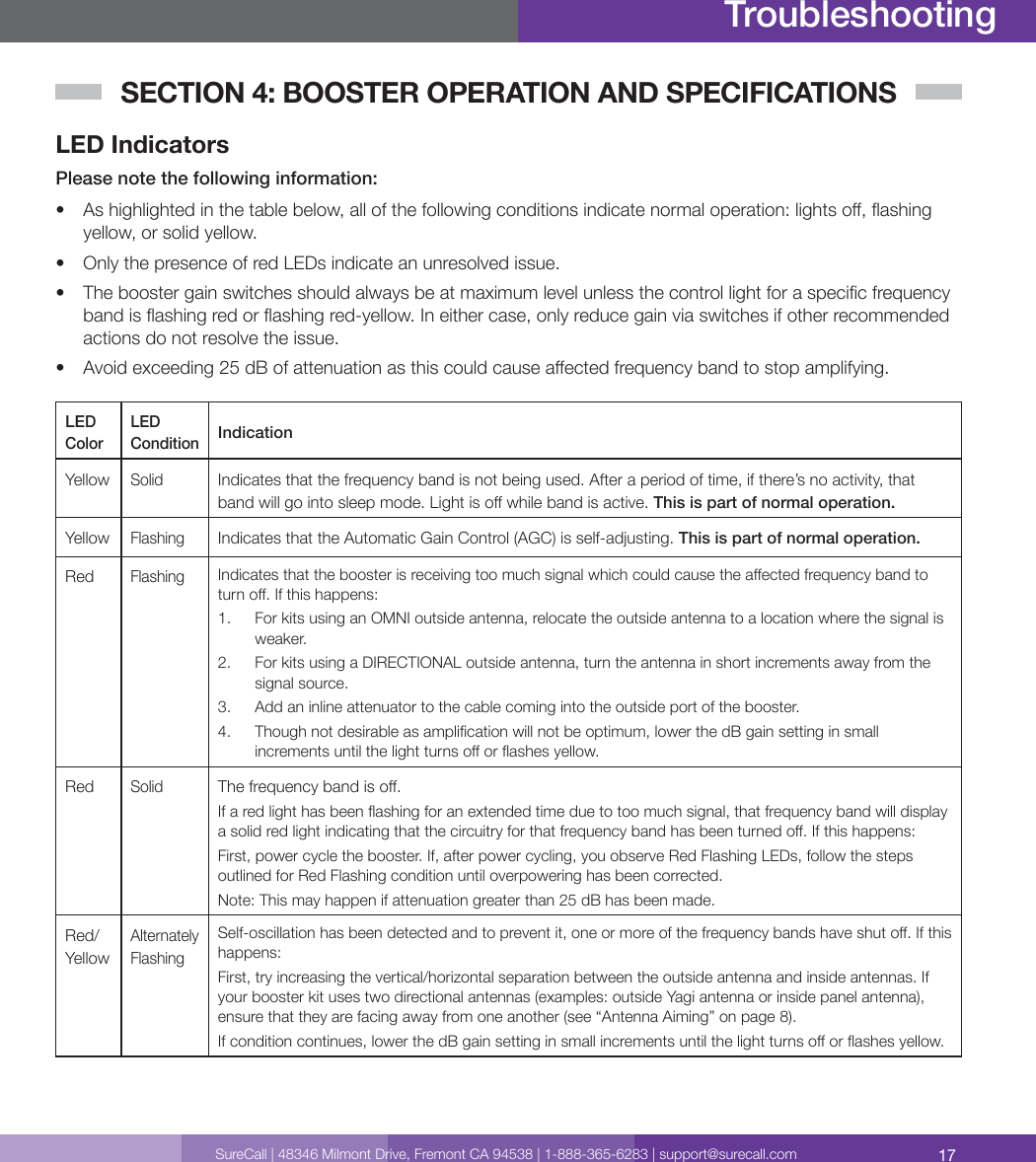
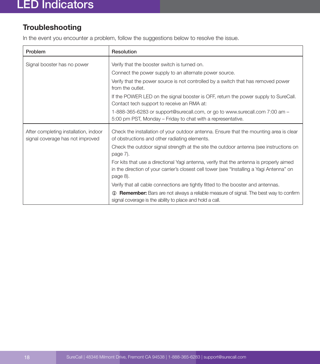
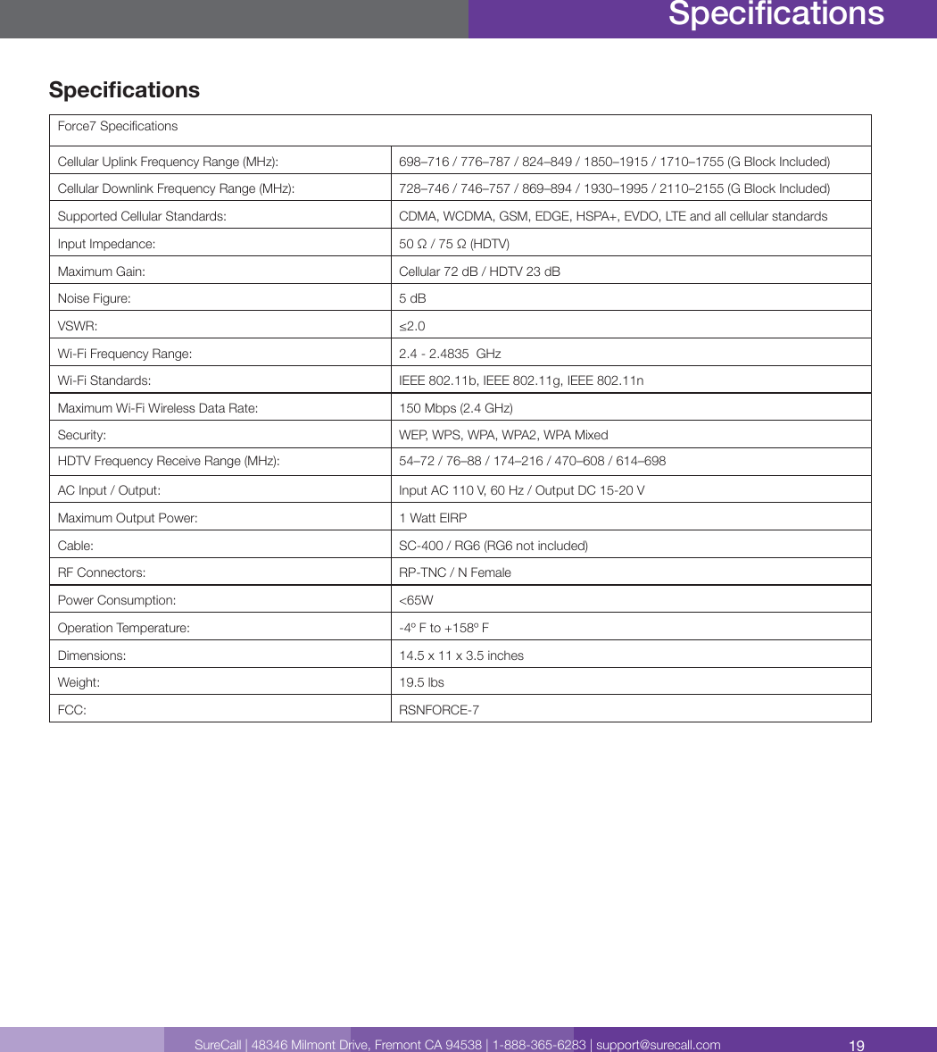
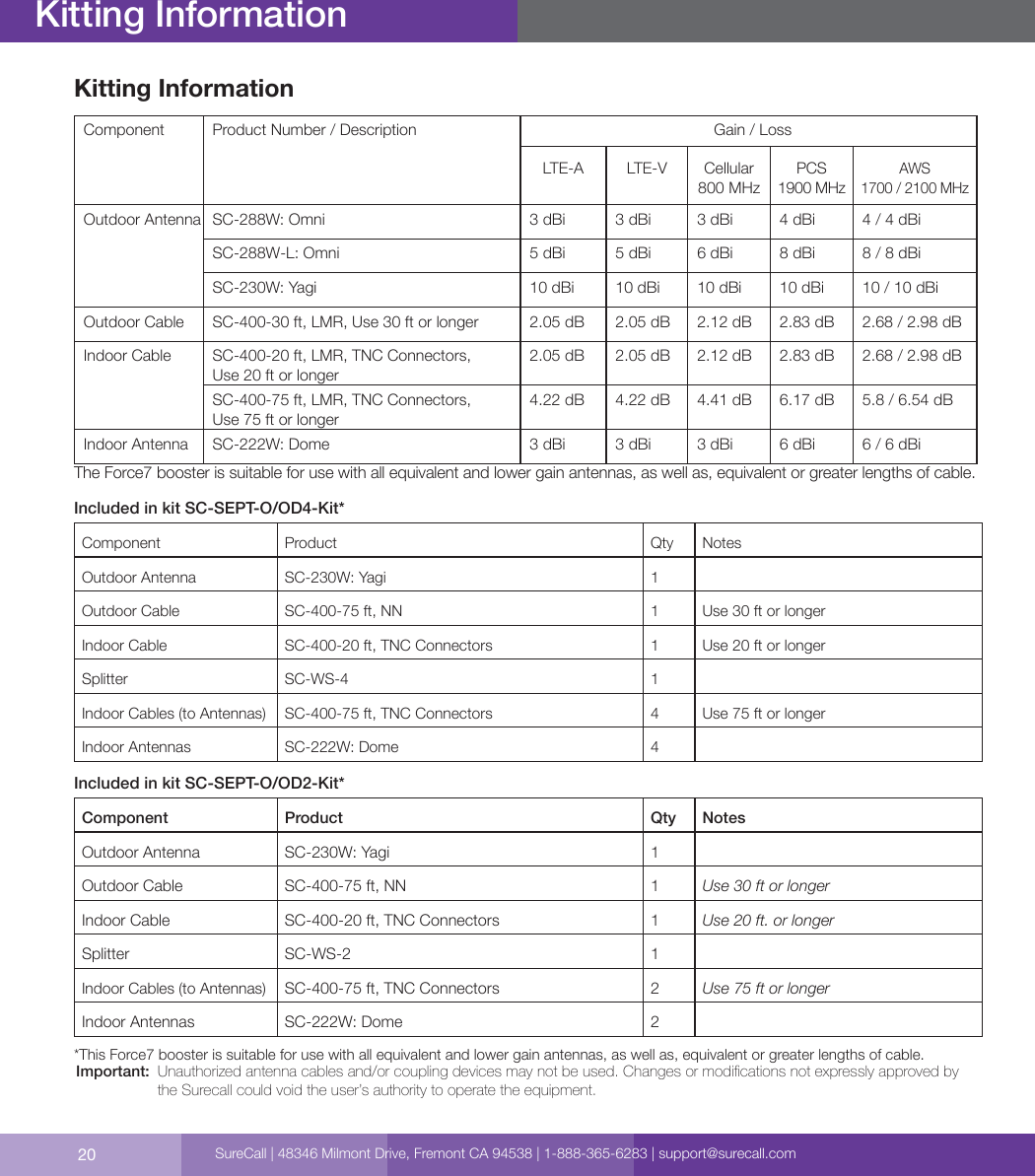
Cellphone-Mate Inc. dba SureCall All in one Cellular, WiFi and HDTV Booster Users Manual

Users Manual

Force7™All-in-One Cellular, Wi-Fi, and HDTV Booster Kit
2Thank you for purchasing SureCall’s Force7 all-in-one cellular, Wi-Fi and HDTV signal booster. Force7 was specically designed to eliminate frustrations over dropped calls, slow 4G data and limited Wi-Fi range, as well as, provide the option to bring locally aired HDTV stations and enhanced streaming video through Netix® and other on-demand streaming media providers.If you have any questions during setup, please reach out to our US-based experienced support technicians:Call: 1-888-365-6283 Email: support@surecall.comOr, chat:  www.surecall.com, 7:00 am – 5:00 pm PST, Monday – FridayWatch installation, optimization and troubleshooting techniques in our SureCall University YouTube channel@SureCall Stay up to date with all things SureCallHow It WorksCellular:SureCall’s Force7 cellular boosting function uses a high-quality bidirectional signal booster that enhances signals to areas that are prone to weak cellular coverage. The cellular component of the Force7 works with two types of antennas: 1)  An outdoor antenna that communicates with the cell tower.2)  A set of Indoor antennas that communicate with your mobile devices.Signals sent from a cell tower are received by the outdoor antenna, amplied by the booster and then sent to your phone via the indoor antennas. When your phone transmits, the signal is sent to the indoor antennas, and then sent to the cell tower via the outdoor antenna.Wi-Fi:The Wi-Fi component of the Force7 works by connecting your external modem to the WAN port on the Force7 with an Ethernet cable (not provided). The booster will then extend your existing Wi-Fi throughout the coverage area. HDTV:The optional HDTV components (not shown in illustration) of the Force7 work with one of two HDTV antenna options. HDTV broadcasts are picked up by the antenna and boosted through the Force7, which connects directly to up to two HDTV devices though RG6 cable (and supports up to 25 devices via cable splitters). This enables the television to access a greater number of high-denition television stations. How It Worksb) Two indoor antenna optiona) Four Indoor antenna optionBoosterOutdoor AntennaIndoor AntennasSureCall | 48346 Milmont Drive, Fremont CA 94538 | 1-888-365-6283 | support@surecall.com
3SureCall | 48346 Milmont Drive, Fremont CA 94538 | 1-888-365-6283 | support@surecall.comTable of ContentsHow It Works .................................................................................................................................................. 2Package Contents .........................................................................................................................................4Kit Options .....................................................................................................................................................4Before Installation ..........................................................................................................................................6Installation Overview ......................................................................................................................................6Section 1: Cellular Component Installation ..................................................................................... 7Step 1. Find the Area Outside with the Strongest Signal  .............................................................................7Step 2. Install the Outdoor Antenna...............................................................................................................7Installing a Yagi Antenna ............................................................................................................................8Installing an Optional Omni Antenna ...........................................................................................................9Step 3. Install the Indoor Antennas  .............................................................................................................10For Each Indoor Dome Antenna:  .............................................................................................................10Step 4. Install the Signal Booster .................................................................................................................12Booster Conguration ..................................................................................................................................13Dip Switches and Lights ..............................................................................................................................13Adjusting Booster Cellular Attenuation ........................................................................................................14Cellular LED Indicators ................................................................................................................................15Section 2: Wi-Fi Connection .......................................................................................................... 15Section 3: HDTV Installation .......................................................................................................... 16Section 4: Booster Operation and Specications ......................................................................... 17LED Indicators .............................................................................................................................................17Troubleshooting ...........................................................................................................................................18Specications ..............................................................................................................................................19Kitting Information ........................................................................................................................................20Three-Year Product Warranty .......................................................................................................................21FCC, IC and Safety Information ...................................................................................................................21Table of Contents
4Package Contents1.  Unpack all package contents. For missing or damaged items, contact your reseller. Keep the carton and packing material to store the product in case you need to return it.2.  Turn over the signal booster and record the model and serial number for reference: Serial #:   _____________________________________________________________________________Purchase Date:  _______________________________________________________________________Kit OptionsForce7 signal booster kits:QTY DescriptionIncluded in kit SC-SEPT-O/OD4-Kit🅐1/ea SureCall Force7 booster and power supply🅑1 Outdoor Yagi antenna🅒175 ft. length of SC-400 coax cable (connects booster to outdoor antenna) 🅓1/ea Lightning protector and 2 ft. SC-400 NN cable (connects to Lightning protector) 🅔120 ft. cable to connect to splitter🅕14-Way splitter 🅖4 75 ft. length of SC-400 TNC coax cable (connects the booster to the indoor antennas) 🅗4 Indoor dome antennasPackage ContentsSureCall | 48346 Milmont Drive, Fremont CA 94538 | 1-888-365-6283 | support@surecall.com
5SureCall | 48346 Milmont Drive, Fremont CA 94538 | 1-888-365-6283 | support@surecall.comPackage ContentsIncluded in kit SC-SEPT-O/OD2-Kit🅐1/ea SureCall Force7 booster and power supply🅑1 Outdoor Yagi antenna🅒175 ft. length of SC-400 coax cable (connects booster to outdoor antenna) 🅓1/ea Lightning protector and 2 ft. SC-400 NN cable (connects to Lightning protector) 🅔120 ft. cable to connect to splitter🅕1 2-Way splitter 🅖275 ft. length of SC-400 TNC coax cable (connects the booster to the indoor antennas) 🅗2Indoor dome antennasHDTV Boosting Accessories (not included)🅙1High-performing outdoor antenna option recommended for spaces with interior walls or obstacles (only one HDTV antenna needed per kit) (SC-306W-H)🅚1Indoor panel antenna option recommended for open indoor spaces (only one HDTV antenna needed per kit) (SC-305W-H)🅛varies RG6 - 50 ft. May be used to connect booster to chosen HTDV antenna -- connect the booster to HDTV device (SC-RG6-50)🅜varies RG6 - 75 ft. May be used to connect booster to chosen HTDV antenna -- connect the booster to HDTV device (SC-RG6-75)
6Before InstallationBefore installation, make note of these important factors:•  A “soft install” is recommended for each section of your installation before permanent placement of parts.•  The booster will need to be close enough to an existing electrical outlet.•  A minimum of 50 ft. of separation between the outdoor antenna and indoor antennas is recommended.•  There will need to be sucient cable length between planned outdoor antenna location and booster connector.•  There will need to be sucient cable length between planned indoor antenna location and booster connector. Additional cable may be purchased if needed.•  An ethernet connection is not required to use the booster’s Wi-Fi function. Direct connection, however, is an option using the booster’s WAN/LAN ports. Should you choose to connect directly to the booster, Ethernet cable of adequate length is needed and has not been provided.Installation OverviewCellular:1.  Find the outside area that has the strongest signal. (See page 7).2.  Install the outdoor antenna in the area identied in step 1. (See page 7).3.  Install the indoor antennas where increased signal is needed. (See page 10).4.  Mount the signal booster, connect the outdoor and indoor antenna cables to the signal booster, and connect the booster to an AC power source. (See page 12).Wi-Fi:1.  Power on the booster. The WAN and WLAN lights on the Fusion7 status LEDs will illuminate2.  On your Wi-Fi device, search for available wireless networks and connect Surecall.3.  Create a password to secure network.HDTV (These parts are available as accessories and not included in your kit):1.  Mount your chosen HDTV antenna (either SC-305W-H or SC-306W-H) in a location appropriate for the chosen antenna.2.  Connect the HDTV antenna to the booster port labeled HDTV OUTSIDE using RG6 cable.  3.  Booster ports on the other end labeled HDTV1 and HDTV2 are used to connect the booster directly to your HDTV devices using RG6 cable. Up to 25 HDTV devices can be supported using cable splitters.Before InstallationFCC 27.5 (d)(4) Statement: Fixed, mobile, and portable (hand-held) stations operating in the 1710-1755 MHz band as well as mobile and portable stations operating in the 1695-1710 MHz and 1755-1780 MHz bands are limited to 1 watt EIRP. Fixed stations operating in the 1710-1755 MHz band are limited to a maximum antenna height of 10 meters above ground. Mobile and portable stations operating in these bands must employ a means for limiting power to the minimum necessary for successful communications.SureCall | 48346 Milmont Drive, Fremont CA 94538 | 1-888-365-6283 | support@surecall.com
7SureCall | 48346 Milmont Drive, Fremont CA 94538 | 1-888-365-6283 | support@surecall.comSECTION 1: CELLULAR COMPONENT INSTALLATIONStep 1. Find the Area Outside with the Strongest Signal Finding Your Strongest Cellular SignalTo send and receive cell phone calls you need to have an adequate cellular signal. This usually means having to be somewhat close to a cell phone tower. Your cellular signal is measured in decibels (dB), which represents the power of the signal. Signal readings appear as a negative number, for example -85 dB. The stronger your signal is the closer it gets to zero. As the illustration below shows a -50 dB signal reading is very strong while a signal reading of -100 dB and above is very weak. How to Determine Your dB Signal Reading•  Using an iPhone: Dial *3001#12345#*, a Field Test screen will appear press down on the home button for a few seconds so your dB reading will appear in the upper left hand corner.•  Using an Android: Download the “Network Signal Info” within the Google Play store. Once installed, you will be able to view your dB strength.•  Internet: Go to: www.speedtest.net to test your 3G and 4G data rates.Signal StrengthExcellent-50 dB-60 dB-70 dB-80 dB-90 dB-100 dBGoodPoorStep 2. Install the Outdoor AntennaThe Force7 kit comes with one directional outside Yagi cellular antenna - however an outside omni antenna may also be used. A directional Yagi antenna works best when facing the direction of the nearest cellular tower being used by your carrierAn omni antenna receives and sends signals in a 360º radius. Before proceeding, please note:•  For both antenna options, mount the outside antenna in the location identied in step 1 and as high as possible. Ensure that the mounting area has at least a 12-inch radius clear of obstructions and other radiating elements. •  For best performance, place the outside antenna at least 50 feet from the inside antenna (see graphic “Antenna Separation” on page 8 . Cellular Installation
8Cellular Installation•  Always orient directional antennas to point away from other system antennas (see illustration, “Antenna Aiming” on page 8).•  Note that if the mounting area is prone to weak cellular signals or if dense building materials partially block the signal, the booster will operate at its default gain setting.Antenna SeparationAntenna SeparationRequired distance between indoor & outdoor antennasOutdoor/ Indoor Antenna SeparationA minimum of 50 ft. of separation between the outdoor antenna and indoor antennas is recommended for best performance. Reducing antenna separation will reduce the coverage provided by the booster and generally, additional separation will provide better performance. Installing a Yagi AntennaBefore installing a Yagi, or directional antenna, note that the antenna should be mounted on a pole or pipe (not provided), at the highest possible location and mounted horizontally, aimed in the direction of your nearest cell tower. To nd the location of your carrier’s closest cell tower, go to www.antennasearch.com. Ensure that the mounting area has at least a 12-inch radius clear of obstructions and other radiating elements and orient the antenna with the drip hole at the bottom. IMPORTANT:  For boosters enhancing T-Mobile’s AWS frequencies, the FCC has stated for consumer signal boosters operating as a xed station in the 1710 - 1755 MHz uplink 2110 - 2155 downlink bands, the users or installation manual must contain the 30 foot height restriction requirements per FCC 27.50(d)(4).OKAntenna AimingOutdoor YagiPlanned booster locationOutdoorCableSC-400Outside Antenna AssemblyNutWasher U-boltBracketDrip HoleRG6 CableSureCall | 48346 Milmont Drive, Fremont CA 94538 | 1-888-365-6283 | support@surecall.com
9SureCall | 48346 Milmont Drive, Fremont CA 94538 | 1-888-365-6283 | support@surecall.comCellular InstallationOutdoor OmniPlanned booster locationOutdoorCableOutdoor Antenna Surface MountNuts & WashersL-BracketCableAnchors /Sleeves ScrewsOnce you have identied your install location, assemble the u-bolt, bracket, nuts and washers onto a pole or pipe (not provided) as shown in the illustration. Keep the connections loose enough to allow the antenna to rotate until the optimum direction is found. Once the outside antenna is secured to a pipe or pole, connect antenna to cable connector of end of the 75 ft. length of cable and run along route to planned location of your booster.Installing an Optional Omni AntennaThe omni antenna is omni-directional, which receives and sends signals in a 360º radius. The provided hardware allow for either a surface mount or pole-mount. The antenna should be mounted in an upright position. See illustration.Note: Do not collocate antennas or operate the outdoor antenna with any other antenna or signal booster.Mount antenna to a vertical surface: 1.  Using vertical plate of bracket, mark position of desired placement. The omni antenna should be mounted in an upright position (See “Omni Outside Antenna Install Illustration” on page 7) 2.  Unscrew nut from end of stucco screw and remove it along with lock washer and regular washer.3.  Place vertical plate into desired location and tap the screws, head rst, along with sleeve, into stucco 1/2 to 5/8 inches deep into place.4.  In this order, place washer, lock washer and nut on each screw and tighten until secure. When tightening screw, sleeve will expand to secure plate.5.  Remove screws from antenna base and use to secure antenna onto horizontal plate.6.  Connect antenna to cable connector of end of the 75 ft. length of cable and run along route to planned location of your booster.
10Cellular InstallationStep 3. Install the Indoor Antennas Indoor antennas for the Force7 come with either four or two omni-directional domes. For either kit option, mount on a ceiling in a central location where signal is needed.The indoor dome multi-band plastic antenna is an omni-directional interior antenna that gathers and sends signals from all sides. Range of antenna is dependent on three factors: 1.  Physical obstructions2.  Power generated by booster 3.  Signal level received by the outdoor antenna4.  Cable lengthFor Each Indoor Dome Antenna: 1.  Drill a 20 mm diameter hole in the ceiling. The ceiling thickness should be 20 mm, maximum.2.  Unscrew xing nut from antenna. Place antenna cable through hole. Screw the xing nut back onto antenna and cable on crawl space side of ceiling and fasten.3.  Connect antenna to cable connector of one of the two or four 75 ft. lengths of SC-400 cable and run along route to planned location of your booster’s 4 way or 2-way splitter. Note: Should there be an excessive length of unneeded cable, optional TNC cable crimpers have been provided in order to shorten the cable.4.  Tighten xing nut to secure antenna (do not over-tighten).5.  Once all indoor antennas and cables are in place, connect cable runs from indoor antennas to the 4-way or 2-way splitter ports.  6.  Connect the provided 20 ft. of SC-400 cable to the remaining end of the splitter and route cable to the planned location of your booster. Note: Be sure to provide the minimum 50 ft. of separation from outdoor antenna (see table on page 8).Important:•  Storage and transportation: Store and place in non-extreme room-temperature and dry environment•  This antenna should not be used near open re or ame.SureCall | 48346 Milmont Drive, Fremont CA 94538 | 1-888-365-6283 | support@surecall.com
11SureCall | 48346 Milmont Drive, Fremont CA 94538 | 1-888-365-6283 | support@surecall.comCellular InstallationYagiOmniOutdoor AntennaOutdoorCable4-Way / 2-Way SplitterIndoor DomeIndoor DomePlanned booster location IndoorCables(75 ft.)IndoorCable(20 ft.)RF CABLETHREADED MOUNTCEILING PLASTIC NUTSC-400INDOOR CABLE
12Hardware InstallationStep 4. Install the Signal BoosterWhen placing the booster, select a location close to a working AC outlet. Do not expose the signal booster to excessive heat, direct sunlight, moisture, and airtight enclosures.1.  Mount 24 inch x 24 inch, 3⁄4 inch thick sheet of plywood on top of sheetrock into wall studs where the booster is to be placed. Plywood should be ush against wall. Once mounted, screw the booster to the plywood sheet. The top side of the booster with the lights and DIP switches should be facing away from the wall and plainly visible standing near the booster.2.  Connect the outdoor antenna cable to the signal booster connector port marked OUTSIDE and tighten the connection.3.  Connect the cable coming from the indoor antennas’ 4-way or 2-way splitter to the booster port marked INSIDE (see page 13) and tighten the connection.4.  Connect the AC power cord to the signal booster.5.  Connect the plug on the other end of the 110V AC power outlet.6.  Turn the booster’s power switch on.Once the booster is powered on:•  The green Power light should illuminate.•  The band lights will ash red and yellow for approximately 10 seconds.Note:     If the Power LED does not turn ON or the Alert LEDs continue to ash, (see “Troubleshooting” on page 18).This booster is rated for 5-20V input voltage. DO NOT use the booster with a higher voltage power supply. This can damage the booster, cause personal injury and void your warranty. Indoor Cables(75 ft.)OutdoorCable(30 ft.)IndoorCable(20 ft.)SplitterForce7Power SupplyIndoor DomeIndoor DomeOmniOutdoor AntennaYagiSureCall | 48346 Milmont Drive, Fremont CA 94538 | 1-888-365-6283 | support@surecall.com
13SureCall | 48346 Milmont Drive, Fremont CA 94538 | 1-888-365-6283 | support@surecall.comBooster ControlsBooster CongurationThe Force7 has 11 dip switches and the frequency bands they utilize for attenuation. Below the image is a general attenuation guide.Dip Switches and LightsBy default, your booster ships with all DIP switches turned OFF to provide maximum gain in all channels. This should always be your starting point whenever installing or reinstalling the booster. When the booster is turned on, the band lights will ash red and yellow for approximately 10 seconds.LTE-A LTE-V CELLULAR PCS AWS Wi-FiWi-FiAWS-DLAWS-ULPCS-DLPCS-ULLTE-V-DLLTE-A-ULHDTV LTE-DLCELLULAR-UL CELLULAR-DL1 2 4 8 16ON1  2  3  4  51 2 4 8 16ON1  2  3  4  51 2 4 8 16ON1  2  3  4  51 2 4 8 16ON1  2  3  4  51 2 4 8 16ON1  2  3  4  51 2 4 8 16ON1  2  3  4  51 2 4 8 16ON1  2  3  4  51 2 4 8 16ON1  2  3  4  51 2 4 8 16ON1  2  3  4  51 2 4 8 16ON1  2  3  4  51 2 4 8 16ON1  2  3  4  5HDTVUPLINK DOWNLINK           Booster Dip SwitchesLTE-A LTE-V CELLULAR AWS Wi-FiWi-FiAWS-DLAWS-ULLTE-V-DLLTE-A-ULHDTV LTE-DLCELLULAR-UL CELLULAR-DL1 2 4 8 16ON1  2  3  4  51 2 4 8 16ON1  2  3  4  51 2 4 8 16ON1  2  3  4  51 2 4 8 16ON1  2  3  4  51 2 4 8 16ON1  2  3  4  51 2 4 8 16ON1  2  3  4  51 2 4 8 16ON1  2  3  4  51 2 4 8 16ON1  2  3  4  51 2 4 8 16ON1  2  3  4  5HDTV PCSPCS-DLPCS-UL1 2 4 8 16ON1  2  3  4  51 2 4 8 16ON1  2  3  4  5LTE-A LTE-V CELLULAR AWS Wi-FiWi-FiAWS-DLAWS-ULLTE-V-DLLTE-A-ULHDTV LTE-DLCELLULAR-UL CELLULAR-DL1 2 4 8 16ON1  2  3  4  51 2 4 8 16ON1  2  3  4  51 2 4 8 16ON1  2  3  4  51 2 4 8 16ON1  2  3  4  51 2 4 8 16ON1  2  3  4  51 2 4 8 16ON1  2  3  4  51 2 4 8 16ON1  2  3  4  51 2 4 8 16ON1  2  3  4  51 2 4 8 16ON1  2  3  4  5HDTV PCSPCS-DLPCS-UL1 2 4 8 16ON1  2  3  4  51 2 4 8 16ON1  2  3  4  5
14Booster Controls1.  HDTV2.  AWS-UL (2100 MHz) Dip switches control AWS uplink (switch 1-5)3.  AWS-DL (2100 MHz) Dip switches control AWS downlink (switch 1-5)4.  PCS-UL (1900 MHz) Dip switches control PCS uplink (switch 1-5)5.  PCS-DL (1900 MHz) Dip switches control PCS downlink (switch 1-5)6.  LTE-UL AT&T (707 MHz) Dip switches control LTE uplink (switch 1-5)7.  LTE-DL (728-757 MHz) Dip switches control LTE downlink (switch 1-5)8.  LTE-UL Verizon (781 MHz) Dip switches control LTE uplink (switch 1-5)9.  CELLULAR-UL (800 MHz) Dip switches control Cellular uplink (switch 1-5) 10. CELLULAR-DL (800 MHz) Dip switches control Cellular downlink (switch 1-5)11. WI-FISwitch 1 (1 dB) + Switch 2 (2 dB) = 3 dB attenuationSwitch 1 (1 dB) + Switch 2 (2 dB) + Switch 3 (4 dB) = 7 dB attenuationSwitch 1 (1 dB) + Switch 2 (2 dB) + Switch 3 (4 dB) + Switch 4 (8 dB) = 1 5 dB attenuationSwitch 1 (1 dB) + Switch 2 (2 dB) + Switch 3 (4 dB) + Switch 4 (8 dB) + Switch 5 (16 dB) = 31 dB attenuationAdjusting Booster Cellular AttenuationBy default, all switches are turned OFF, meaning all frequency bands are operating at full gain. •  Turning a switch OFF increases booster gain for the selected channel.•  Turning a switch ON adds attenuation (reduced amplication) for the selected channel.Switches should remain in the OFF position unless red ashing lights occur for a channel or channels. Red ashing lights indicate that the system has detected oscillation for the corresponding channel(s) and turn o if adjustments are not made.ATTENUATION: Reduced amplicationKeep in mind when adjusting the booster: Full power is not always the best option. Your goal is to obtain a usable cellular signal in as many areas of the building as possible. A successful installation means that you can make calls without dropping and/or have a reliable data connection.Each bank of DIP switches contain ve switches. From left to right, the DIP switches in each bank provide 1, 2, 4, 8, and 16 dB of attenuation (reduced amplication). These switches are cumulative, meaning that the total amount of attenuation for a channel is equal to the combined dB of all ON DIP switches in the corresponding bank. Switch 1       Switch 2          Switch 3          Switch 4         Switch 5  1 dB                 2 dB             4 dB               8 dB               16 dB1 2 4 8 16DOWNLINKUPLINK124 8 161  2  3  4  5PCS-DLPCS-UL1 2 4 8 161 2 4 8 161  2  3  4  5SureCall | 48346 Milmont Drive, Fremont CA 94538 | 1-888-365-6283 | support@surecall.com
15SureCall | 48346 Milmont Drive, Fremont CA 94538 | 1-888-365-6283 | support@surecall.comWi-Fi ConnectionExample:•  Turning all switches OFF = 0 dB attenuation (booster is at full gain).•  Turning ON Switch #1 in a bank = 1 dB attenuation (booster maximum gain is reduced by 1 dB).•  Turning ON Switches #1, 3, and 5 in a bank = 1+4+16 dB attenuation = 21 dB attenuation.•  In an 80 dB booster, this means the selected channel would be reduced to 59 dB (80 dB -21 dB).•  Turning ON all switches in a bank = 1+2+4+8+16 dB attenuation = 31 dB attenuationIn an 80 dB booster, that means that the selected channel would be reduced to 49 dB (80 dB-31 dB).TestingOnce the booster is powered on and no Warning lights are illuminated, walk around the entire area to test the voice and/or data signal. Rene the antenna locations and/or gain levels as needed, and then complete the permanent installation once the system is working as desired. Remember: Bars are not always a reliable measure of signal. The best way to conrm signal coverage is the ability to place and hold a call. Cellular LED IndicatorsPlease note that the following conditions indicate normal operation: lights o, ashing yellow, or solid yellow.Only the presence of red LEDs indicate an unresolved issue. The booster gain switches should always be at maximum level unless the control light for a specic frequency band is ashing red or ashing red-yellow. In either case, only reduce gain via switches if other recommended actions do not resolve the issue. For the LED chart, see page 17 Avoid exceeding 25 dB of attenuation as this could cause aected frequency band to stop amplifying. SECTION 2: WI-FI CONNECTIONInstallation Instructions: Before beginning this part of the installation, the booster should be powered on.1.  The WAN and WLAN lights on the Fusion7 status LEDs will illuminate when booster is powered on.2.  On your Wi-Fi device, search available wireless networks and choose Surecall. A security password isn’t needed.3.  The Surecall network is unsecured by default. You must create a password to secure the network. To Create a Secure Password: •  Enter this default IP address: 192.168.2.1 in your web browser. You will be connected to the Force7’s conguration page.•  Go to the Wireless section on the left side of the screen.•  Go to security link and choose the type of encryption you wish to use. WPA-Mixed is recommended for strongest encryption.•  Enter a new password in the Pre-Shared/Encryption key window.•  Apply your settings and you will be prompted to reboot. •  Once rebooted, verify you are connected to the Surecall. You may need to reconnect.
16Note: To access advanced settings for the internal router, contact SureCall at: 888-365-6283 for the complete router user manual.SECTION 3: HDTV INSTALLATIONHDTV Installation Instructions (These parts are available as accessories and not included in your kit):Before beginning this part of the installation, turn the booster’s power switch o.1.  Mount your chosen HDTV antenna (either SC-305W-H or SC-306W-H) in a location appropriate for the chosen antenna.2.  Connect the HDTV antenna to the booster port labeled HDTV OUTSIDE using RG6 cable.  3.  Booster ports on the other end labeled HDTV1 and HDTV2 are used to connect the booster directly to your HDTV device(s) using RG6 cable or up to 25 devices using cable splitters. 4.  Turn the booster’s power switch on.Scanning Local Television Channels.1.  On your TV’s remote control, press the Input or Source button. From there, you’ll select “TV” or “Air”. Consult you TV manual for detailed instructions. 2.  After selecting “Antenna” or “Air” press the menu button. Choose the antenna option followed by Auto Program. 3.  You may then need to select the Air button where you can start searching for local channels. 4.  The TV will automatically search all available stations. Once the scan is complete, you can exit your TV menu and begin watching free, high-denition televisionHDTV InstallationSureCall | 48346 Milmont Drive, Fremont CA 94538 | 1-888-365-6283 | support@surecall.com
17SureCall | 48346 Milmont Drive, Fremont CA 94538 | 1-888-365-6283 | support@surecall.comTroubleshootingSECTION 4: BOOSTER OPERATION AND SPECIFICATIONSLED IndicatorsPlease note the following information:•  As highlighted in the table below, all of the following conditions indicate normal operation: lights o, ashing yellow, or solid yellow.•  Only the presence of red LEDs indicate an unresolved issue. •  The booster gain switches should always be at maximum level unless the control light for a specic frequency band is ashing red or ashing red-yellow. In either case, only reduce gain via switches if other recommended actions do not resolve the issue.  •  Avoid exceeding 25 dB of attenuation as this could cause aected frequency band to stop amplifying. LED ColorLED ConditionIndicationYellowSolidIndicates that the frequency band is not being used. After a period of time, if there’s no activity, that band will go into sleep mode. Light is o while band is active. This is part of normal operation. Yellow FlashingIndicates that the Automatic Gain Control (AGC) is self-adjusting. This is part of normal operation.RedFlashingIndicates that the booster is receiving too much signal which could cause the aected frequency band to turn o. If this happens:1.  For kits using an OMNI outside antenna, relocate the outside antenna to a location where the signal is weaker.2.  For kits using a DIRECTIONAL outside antenna, turn the antenna in short increments away from the signal source.3.  Add an inline attenuator to the cable coming into the outside port of the booster.4.  Though not desirable as amplication will not be optimum, lower the dB gain setting in small increments until the light turns o or ashes yellow.RedSolidThe frequency band is o.If a red light has been ashing for an extended time due to too much signal, that frequency band will display a solid red light indicating that the circuitry for that frequency band has been turned o. If this happens: First, power cycle the booster. If, after power cycling, you observe Red Flashing LEDs, follow the steps outlined for Red Flashing condition until overpowering has been corrected.Note: This may happen if attenuation greater than 25 dB has been made. Red/YellowAlternately FlashingSelf-oscillation has been detected and to prevent it, one or more of the frequency bands have shut o. If this happens: First, try increasing the vertical/horizontal separation between the outside antenna and inside antennas. If your booster kit uses two directional antennas (examples: outside Yagi antenna or inside panel antenna), ensure that they are facing away from one another (see “Antenna Aiming” on page 8).If condition continues, lower the dB gain setting in small increments until the light turns o or ashes yellow.
18LED IndicatorsTroubleshootingIn the event you encounter a problem, follow the suggestions below to resolve the issue.Problem ResolutionSignal booster has no power Verify that the booster switch is turned on.Connect the power supply to an alternate power source.Verify that the power source is not controlled by a switch that has removed power from the outlet.If the POWER LED on the signal booster is OFF, return the power supply to SureCall. Contact tech support to receive an RMA at: 1-888-365-6283 or support@surecall.com, or go to www.surecall.com 7:00 am – 5:00 pm PST, Monday – Friday to chat with a representative.After completing installation, indoor signal coverage has not improvedCheck the installation of your outdoor antenna. Ensure that the mounting area is clear of obstructions and other radiating elements. Check the outdoor signal strength at the site the outdoor antenna (see instructions on page 7).For kits that use a directional Yagi antenna, verify that the antenna is properly aimed in the direction of your carrier’s closest cell tower (see “Installing a Yagi Antenna” on page 8).Verify that all cable connections are tightly tted to the booster and antennas.  Remember: Bars are not always a reliable measure of signal. The best way to conrm signal coverage is the ability to place and hold a call. SureCall | 48346 Milmont Drive, Fremont CA 94538 | 1-888-365-6283 | support@surecall.com
19SureCall | 48346 Milmont Drive, Fremont CA 94538 | 1-888-365-6283 | support@surecall.comSpecicationsSpecicationsForce7 SpecicationsCellular Uplink Frequency Range (MHz): 698–716 / 776–787 / 824–849 / 1850–1915 / 1710–1755 (G Block Included)Cellular Downlink Frequency Range (MHz): 728–746 / 746–757 / 869–894 / 1930–1995 / 2110–2155 (G Block Included)Supported Cellular Standards: CDMA, WCDMA, GSM, EDGE, HSPA+, EVDO, LTE and all cellular standardsInput Impedance: 50 Ω / 75 Ω (HDTV)Maximum Gain: Cellular 72 dB / HDTV 23 dBNoise Figure: 5 dBVSWR: ≤2.0Wi-Fi Frequency Range: 2.4 - 2.4835  GHzWi-Fi Standards: IEEE 802.11b, IEEE 802.11g, IEEE 802.11nMaximum Wi-Fi Wireless Data Rate: 150 Mbps (2.4 GHz)Security: WEP, WPS, WPA, WPA2, WPA MixedHDTV Frequency Receive Range (MHz): 54–72 / 76–88 / 174–216 / 470–608 / 614–698AC Input / Output: Input AC 110 V, 60 Hz / Output DC 15-20 VMaximum Output Power: 1 Watt EIRPCable: SC-400 / RG6 (RG6 not included)RF Connectors: RP-TNC / N FemalePower Consumption: <65WOperation Temperature: -4º F to +158º FDimensions: 14.5 x 11 x 3.5 inchesWeight: 19.5 lbsFCC: RSNFORCE-7
20Kitting InformationSureCall | 48346 Milmont Drive, Fremont CA 94538 | 1-888-365-6283 | support@surecall.comKitting InformationComponent Product Number / Description Gain / LossLTE-A LTE-V Cellular  800 MHzPCS  1900 MHzAWS  1700 / 2100 MHzOutdoor Antenna SC-288W: Omni 3 dBi 3 dBi 3 dBi 4 dBi 4 / 4 dBiSC-288W-L: Omni 5 dBi 5 dBi 6 dBi 8 dBi 8 / 8 dBiSC-230W: Yagi 10 dBi 10 dBi 10 dBi 10 dBi 10 / 10 dBiOutdoor Cable SC-400-30 ft, LMR, Use 30 ft or longer 2.05 dB 2.05 dB 2.12 dB 2.83 dB 2.68 / 2.98 dB Indoor Cable SC-400-20 ft, LMR, TNC Connectors,  Use 20 ft or longer 2.05 dB 2.05 dB 2.12 dB 2.83 dB 2.68 / 2.98 dBSC-400-75 ft, LMR, TNC Connectors,  Use 75 ft or longer4.22 dB 4.22 dB 4.41 dB 6.17 dB 5.8 / 6.54 dBIndoor Antenna SC-222W: Dome 3 dBi 3 dBi 3 dBi 6 dBi 6 / 6 dBiThe Force7 booster is suitable for use with all equivalent and lower gain antennas, as well as, equivalent or greater lengths of cable.Included in kit SC-SEPT-O/OD4-Kit*Component Product Qty NotesOutdoor Antenna SC-230W: Yagi 1Outdoor Cable SC-400-75 ft, NN 1Use 30 ft or longerIndoor Cable SC-400-20 ft, TNC Connectors 1Use 20 ft or longerSplitter SC-WS-4 1Indoor Cables (to Antennas) SC-400-75 ft, TNC Connectors 4 Use 75 ft or longerIndoor Antennas SC-222W: Dome 4Included in kit SC-SEPT-O/OD2-Kit* Component Product Qty NotesOutdoor Antenna SC-230W: Yagi 1Outdoor Cable SC-400-75 ft, NN 1Use 30 ft or longerIndoor Cable SC-400-20 ft, TNC Connectors 1Use 20 ft. or longerSplitter SC-WS-2 1Indoor Cables (to Antennas) SC-400-75 ft, TNC Connectors 2Use 75 ft or longerIndoor Antennas SC-222W: Dome 2*This Force7 booster is suitable for use with all equivalent and lower gain antennas, as well as, equivalent or greater lengths of cable.Important:      Unauthorized antenna cables and/or coupling devices may not be used. Changes or modications not expressly approved by the Surecall could void the user’s authority to operate the equipment.
21SureCall | 48346 Milmont Drive, Fremont CA 94538 | 1-888-365-6283 | support@surecall.comWarrantyThree-Year Product WarrantyRegister at www.SureCall.comSureCall warrants its products for three years from the date of purchase against defects in workmanship and/or materials. Specications are subject to change. The three-year warranty only applies to products meeting the latest FCC Certication Guidelines stated on 2/20/2013 and going into eect April 30, 2014. A two-year warranty applies to any products manufactured before May 1, 2014.Products returned by customers must be in their original, un-modied condition, shipped in the original or protective packaging with proof-of-purchase documentation enclosed, and a Return Merchandise Authorization (RMA) number printed clearly on the outside of the shipping container.Buyers may obtain an RMA number for warranty returns by calling the SureCall Return Department toll-free at 1-888-365-6283. Any returns received by SureCall without an RMA number clearly printed on the outside of the shipping container will be returned to sender. In order to receive full credit for signal boosters, all accessories originally included in the signal booster box must be returned with the signal booster. (The Buyer does not need to include accessories sold in addition to the signal booster, such as antennas or cables.) This warranty does not apply to any product determined by SureCall to have been subjected to misuse, abuse, neglect, or mishandling that alters or damages the product’s physical or electronic properties.SureCall warrants to the Buyer that each of its products, when shipped, will be free from defects in material and workmanship, and will perform in full accordance with applicable specications. The limit of liability under this warranty is, at SureCall’s option, to repair or replace any product or part thereof which was purchased up to THREE YEARS after May 1, 2014 or TWO YEARS for products purchased before May 1, 2014, as determined by examination by SureCall, prove defective in material and/or workmanship. Warranty returns must rst be authorized in writing by SureCall. Disassembly of any SureCall product by anyone other than an authorized representative of SureCall voids this warranty in its entirety. SureCall reserves the right to make changes in any of its products without incurring any obligation to make the same changes on previously delivered products. As a condition to the warranties provided for herein, the Buyer will prepay the shipping charges for all products returned to SureCall for repair, and SureCall will pay the return shipping with the exception of products returned from outside the United States, in which case the Buyer will pay the shipping charges. The Buyer will pay the cost of inspecting and testing any goods returned under the warranty or otherwise, which are found to meet the applicable specications or which are not defective or not covered by this warranty. Products sold by SureCall shall not be considered defective or non-conforming to the Buyer’s order if they satisfactorily fulll the performance requirements that were published in the product specication literature, or in accordance with samples provided by SureCall. This warranty shall not apply to any products or parts thereof which have been subject to accident, negligence, alteration, abuse, or misuse. SureCall makes no warranty whatsoever in respect to accessories or parts not supplied by it.Limitations of Warranty, Damages and Liability:EXCEPT AS EXPRESSLY SET FORTH HEREIN, THERE ARE NO WARRANTIES, CONDITIONS, GUARANTEES, OR REPRESENTATIONS AS TO MERCHANTABILITY, FITNESS FOR A PARTICULAR PURPOSE, OR OTHER WARRANTIES, CONDITIONS, GUARANTEES, OR REPRESENTATIONS, WHETHER EXPRESSED OR IMPLIED, IN LAW OR IN FACT, ORAL OR IN WRITING.SURECALL AGGREGATE LIABILITY IN DAMAGES OR OTHERWISE SHALL NOT EXCEED THE PAYMENT, IF ANY, RECEIVED BY CELLPHONE-MATE, INC. FOR THE UNIT OF PRODUCT OR SERVICE FURNISHED OR TO BE FURNISHED, AS THE CASE MAY BE, WHICH IS THE SUBJECT OF CLAIM OR DISPUTE. IN NO EVENT SHALL SURECALL BE LIABLE FOR INCIDENTAL, CONSEQUENTIAL, OR SPECIAL DAMAGES, HOWSOEVER CAUSED. All matters regarding this warranty shall be interpreted in accordance with the laws of the State of California, and any controversy that cannot be settled directly shall be settled by arbitration in California in accordance with the rules then prevailing of the American Arbitration Association, and judgment upon the award rendered may be entered in any court having jurisdiction thereof. If one or more provisions provided herein are held to be invalid or unenforceable under applicable law, then such provision shall be ineective and excluded to the extent of such invalidity or unenforceability without aecting in any way the remaining provisions hereof.FCC, IC and Safety InformationSureCall has made a good faith eort to ensure the accuracy of the information in this document and disclaims the implied warranties of merchantability and tness for a particular purpose and makes no express warranties, except as may be stated in its written agreement with and for its customers. SureCall shall not be held liable to anyone for any indirect, special or consequential damages due to omissions or errors. The information and specications in this document are subject to change without notice.
22FCC, IC and SafetySureCall | 48346 Milmont Drive, Fremont CA 94538 | 1-888-365-6283 | support@surecall.com© 2017. All Rights Reserved. All trademarks and registered trademarks are the property of their respective owners.48346 Milmont DriveFremont, California 94538, USA888.365.6283www.surecall.comImportant: Before installing your booster you need to register it with your carrier. You can do so online at the following urls:Verizon: http://www.verizonwireless.com/wcms/consumer/register-signal-booster.htmlAT&T: https://securec45.securewebsession.com/attsignalbooster.com/T-Mobile: https://support.t-mobile.com/docs/DOC-9827 Sprint: https://www.sprint.com/legal/fcc_boosters.htmlU.S. Cellular: http://www.uscellular.com/uscellular/support/fcc-booster-registration.jspFCC Information:This is a CONSUMER device.BEFORE USE, you MUST REGISTER THIS DEVICE with your wireless provider and have your provider’s consent. Most wireless providers consent to the use of signal boosters. Some providers may not consent to the use of this device on their network. If you are unsure, contact your provider. You MUST operate this device with approved antennas and cables as specied by the manufacturer. Antennas MUST be installed at least 20 cm (8 inches) from any person. You MUST cease operating this device immediately if requested by the FCC or a licensed wireless service provider.This device may be operated ONLY in a xed location for in-building use.WARNING: E911 location information may not be provided or may be inaccurate for calls served BY USING THIS DEVICE.Note: This equipment has been tested and found to comply with the limits for a Class B digital device, pursuant to part 15 of the FCC Rules. These limits are designed to provide reasonable protection against harmful interference in a residential installation. This equipment generates, uses and can radiate radio frequency energy and, if not installed and used in accordance with the instructions, may cause harmful interference to radio communications. However, there is no guarantee that interference will not occur in a particular installation. If this equipment does cause harmful interference to radio or television reception, which can be determined by turning the equipment o and on, the user is encouraged to try to correct the interference by one or more of the following measures:   •  Reorient or relocate the receiving antenna•  Increase the separation between the equipment and receiver.•  Connect the equipment into an outlet on a circuit dierent from that to which the receiver is connected•  Consult the dealer or an experienced radio/TV technician for help.15.19 This device complies with Part 15 of the FCC Rules. Operation is subject to the following two conditions:  (1)  this device may not cause harmful interference, and (2) this device must accept any interference received, including interference that may cause undesired operation.Industry Canada:This Class A digital apparatus meets all requirements of the Canadian Interference Causing Equipment Regulations. Operation is subject to the following two conditions: (1) this device may not cause harmful interference, and (2) this device must accept any interference received, including interference that may cause undesired operationCet appareillage numérique de la classe A répond a toutes les exigencies de l’interférence canadienne causant des réglements d’équipment. L’opération est sujette aux deux conditions suivantes: (1) ce dispositif peut ne pas causer l’interférence nocive, et (2) ce dispositif doit accepter n’importe quelle intérference reçue, y compris l’intérference qui peut causer l’opération peu désirée.The Manufacturer’s rated output power of this equipment is for single carrier operation. For situations when multiple carrier signals are present, the rating would have to be reduced by 3.5 dB, especially where the output signal is re-radiated and can cause interference to adjacent band users. This power reduction is to be by means of input power or gain reduction and not by an attenuator at the output of the device.La puissance de sortie nominale indiquée par le fabricant pour cet appareil concerne son fonctionnement avec porteuse unique. Pour des appareils avec porteuses multiples, on doit réduire la valeur nominale de 3,5 dB, surtout si le signal de sortie est retransmis et qu’il peut causer du brouillage aux utilisateurs de bandes adjacentes. Une telle réduction doit porter sur la puissance d’entrée ou sur le gain, et ne doit pas se faire au moyen d’un atténuateur raccordé à la sortie du dispositif
23SureCall | 48346 Milmont Drive, Fremont CA 94538 | 1-888-365-6283 | support@surecall.comFCC, IC and Safety
BEFORE USE, you MUST REGISTER THIS DEVICE with your wireless provider and have your provider’s consent. Most wireless providers consent to the use of signal boosters. Some providers may not consent to the use of this device on their network. If you are unsure, contact your provider.You MUST operate this device with approved antennas and cables as specied by the manufacturer. Antennas MUST be installed at least 20 cm (8 inches) from any person. You MUST cease operating this device immediately if requested by the FCC or a licensed wireless service provider.WARNING. E911 location information may not be provided or may be inaccurate for calls served by using this device.This device may be operated ONLY in a xed location for in-building use.This is a CONSUMER device.Note: This equipment has been tested and found to comply with the limits for a Class B digital device, pursuant to part 15 of the FCC Rules. These limits are designed to provide reasonable protection against harmful interference in a residential installation. This equipment generates, uses and can radiate radio frequency energy and, if not in-stalled and used in accordance with the instructions, may cause harmful interference to radio communications. However, there is no guarantee that interference will not occur in a particular installation. If this equipment does cause harmful interference to radio or television reception, which can be determined by turning the equipment off and on, the user is encouraged to try to correct the interference by one or more of the following measures:        •  Reorient or relocate the receiving antenna.              •  Increase the separation between the equipment and receiver.                               •  Connect the equipment into an outlet on a circuit different from that to which the receiver is connected.                                                                                                                   •  Consult the dealer or an experienced radio/TV technician for help.FCC 27.50(d)(4) Statement: Fixed, mobile and portable (hand-held) stations operating in the 1720-1755 MHz band are limited 1 Watt EIRP. Fixed stations operating in this band are limited to a maximum antenna height of 10 meters above ground. Mobile and portable stations operating in this band must employ a means for limiting power to the minimum necessary for successful communications.

Navigation menu