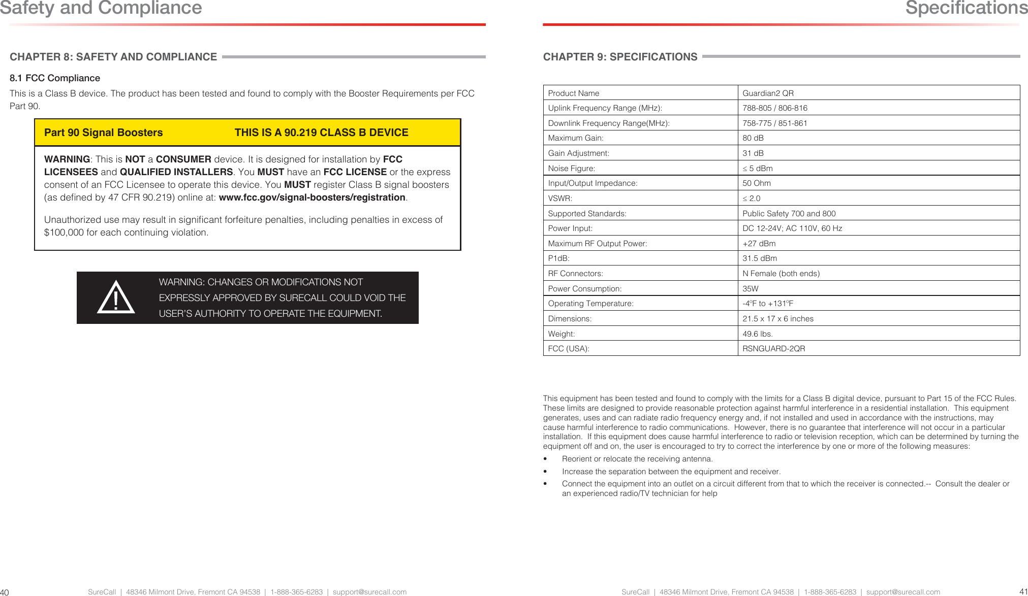
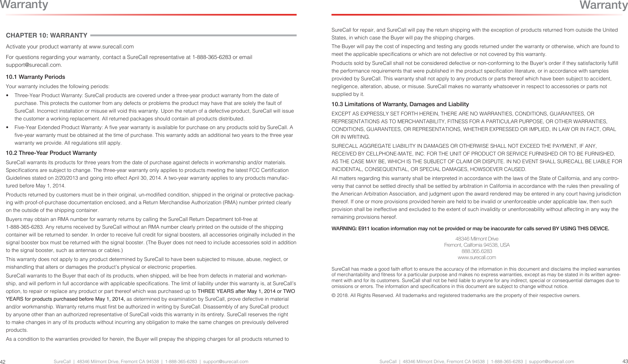
Cellphone Mate SureCall GUARD-2QR Dual band public safety signal booster User Manual

Cellphone-Mate Inc. dba SureCall Dual band public safety signal booster Users Manual

Users Manual

SureCall Guardian2 QR(Quick Response)™  User and Installation GuidePublic Safety Bands BDA for First RespondersSupports 700 MHz (FirstNet Ready) and 800 MHz bands07.13.2018
SureCall  |  48346 Milmont Drive, Fremont CA 94538  |  1-888-365-6283  |  support@surecall.comFCC NOTICEThe SureCall Guardian2 QR signal booster is a 90.219 Class B Device. Under Section 90.219(d)(5) of the Commission’s rules, all Part 90 Class B signal booster installations must be registered with the FCC. In February 2013, as part of the Commission’s efforts to support the continued use of signal boosters in the Private Land Mobile Radio Services and Public Safety Radio Services, the Commission adopted a registration requirement for existing and future Part 90 Class B signal booster installations. The Commission found that a Class B signal booster registration system would be a valuable tool to help resolve interference should it occur.All Part 90 licensees and signal-booster operators must register existing Part 90 Class B signal boosters with the Commission by November 1, 2014. In addition, any new Class B signal booster installed after November 1, 2014 must be registered prior to operation.Filing Registrations. To register a Part 90 Class B signal booster, go to the Part 90 Signal Booster Registration and Discovery page at www.fcc.gov/signal-boosters/registration. Enter an FCC Registration Number (FRN) and Password in the upper-right corner of the screen. Then click on “LOGIN.”On the Signal Booster Information page, enter either (1) latitude and longitude (in decimal degrees) of the booster location and click on the “Get Address Info” button; or (2) the booster, city, and state, and click on the “Get Lat/Long button. The registration tool will provide a map of the booster location to verify the location is correct. Next, check the box(es) for the frequencies within the operating range of the signal booster and enter at least one call sign associated with the booster. Then  enter  the  ler’s  Company  Information  (Company  Name,  Company  Attention,  Address,  Email  registration,  enter Signature Information (Title, Name), and click “Submit.” The system will generate a conrmation, including a booster ID number, which you may print for your records. Each booster must be submitted separately. Using the links in the upper-right corner of the Signal Booster Conrmation page, you can “Add a Booster,” “View Your Boosters” or “Log out.”Accessing Registrations. Each registration will be available to the public on the same day it is led with the Commission. Registrations may be accessed at: www.fcc.gov/signal-boosters/registration. Click on “View All Boosters” from the Part 90 Signal Booster Registration and Discovery page. The registrations can be searched and sorted by booster ID number, name of the ler, city, county, state, zip code, latitude/longitude, or call sign.For further information please contact the FCC Licensing Support Hotline at (877) 480-3201 or submit an online help request at https://esupport.ffc.gov/onlinerequest.htm. Support hours are Monday thru Friday, 8:00–6:00 p.m. Eastern Time, except for Federal holidays.SureCall  |  48346 Milmont Drive, Fremont CA 94538  |  1-888-365-6283  |  support@surecall.com 32Table of ContentsFCC NoticeFCC Notice ................................................................................................................................................................................2Chapter 1: Introduction & Overview...........................................................................................................................................41.1 Product Overview .....................................................................................................................................................................................41.2 Package Contents ....................................................................................................................................................................................41.3 Additional Items Needed ..........................................................................................................................................................................41.4 Key Features & Benets ...........................................................................................................................................................................41.5 Optional Accessories ...............................................................................................................................................................................51.6 How it Works .............................................................................................................................................................................................61.8 Single vs. Multiple Carrier Operation .......................................................................................................................................................61.9 A Word About Safety ................................................................................................................................................................................6Chapter 2: BDA Interface & Connections ..................................................................................................................................72.1 Guardian2 QR BDA Interface Overview  ..................................................................................................................................................72.2 RF Interfaces (A1 & A6) ............................................................................................................................................................................82.3 Power Interface for 110VAC or UPS Output (A5) .....................................................................................................................................82.4 DC12-20V Interface (A9) ..........................................................................................................................................................................92.5 RS-232 Connector - (A3)  .........................................................................................................................................................................92.6 Alarm I/O Interface (A2) .........................................................................................................................................................................102.7 RF Module Summary Alarms Trigger Criteria .........................................................................................................................................112.8 VSWR Alarm Trigger Criteria ..................................................................................................................................................................122.9 Load Restrictions ....................................................................................................................................................................................132.10 Ethernet Interface (A4) .........................................................................................................................................................................132.11 USB Interface (A7) ...............................................................................................................................................................................142.12 Alarm LEDs (A8)  ..................................................................................................................................................................................15Chapter 3: Planning the Installation.........................................................................................................................................163.1 Installation Overview ..............................................................................................................................................................................163.2 Exterior Antenna Overview .....................................................................................................................................................................173.3 Interior Antenna Overview ......................................................................................................................................................................173.4 Antenna Separation ................................................................................................................................................................................183.5 BDA Location  ........................................................................................................................................................................................193.6 Accessories ............................................................................................................................................................................................193.7 Need Help? ............................................................................................................................................................................................20Chapter 4: Installation..............................................................................................................................................................214.1 Soft Installation .......................................................................................................................................................................................214.2 Exterior Antenna .....................................................................................................................................................................................214.3 Interior Antennas ....................................................................................................................................................................................224.4 Mounting the BDA ..................................................................................................................................................................................23Chapter 5: Conguration & Testing ..........................................................................................................................................245.1 Powering on the BDA .............................................................................................................................................................................245.2 DIP Switch Conguration ........................................................................................................................................................................24Chapter 6: Testing And Troubleshooting ..................................................................................................................................266.1 Band LED Conditions .............................................................................................................................................................................266.2 LED Conditions .......................................................................................................................................................................................276.3 Testing & Troubleshooting .....................................................................................................................................................................27Chapter 7: Sentry Conguration & Monitoring .........................................................................................................................287.1 Sentry Software Introduction ..................................................................................................................................................................287.2 Software Installation ...............................................................................................................................................................................287.3 Hardware Installation ..............................................................................................................................................................................327.4 Conguring the Booster System .............................................................................................................................................................34Chapter 8: Safety And Compliance .........................................................................................................................................408.1 FCC Compliance  ...................................................................................................................................................................................40Chapter 9: Specications.........................................................................................................................................................41Chapter 10: Warranty ..............................................................................................................................................................4210.1 Warranty Periods ..................................................................................................................................................................................4210.2 Three-Year Product Warranty ...............................................................................................................................................................4210.3 Limitations of Warranty, Damages and Liability ...................................................................................................................................43
SureCall  |  48346 Milmont Drive, Fremont CA 94538  |  1-888-365-6283  |  support@surecall.com SureCall  |  48346 Milmont Drive, Fremont CA 94538  |  1-888-365-6283  |  support@surecall.com 54Introduction & OverviewCHAPTER 1: INTRODUCTION & OVERVIEW1.1 Product OverviewSureCall’s Guardian2 QR is a bi-directional communications amplier for police headquarters, re stations, hospitals, and other rst-responder facilities. The BDA services the full public safety 700MHz and 800MHz bands.The Guardian2 QR signicantly improves the quality of crucial rst-responder communications in buildings with weak signal strength. For optimal coverage, the BDA uses built-in safeguards to eliminate interference to public-safety networks. It meets NEMA 4 type requirements, and is upgradable in the eld. Plus, the Guardian2 QR offers the industry’s best three-year warranty available.The Guardian2 QR is enclosed in a NEMA-4 compatible housing, and enhances the coverage area of rst responder radio communications for in-building applications. It is equipped with bi-directional paths (down-link & up-link) for transmit and receive frequencies, and advanced ltering technology for low-noise amplication of signals.1.2 Package ContentsYour BDA box contains the following items:•  Guardian2 bi-directional amplier•  NEMA-4 rated housing•  AC power cable•  DC power cable and connector•  Alarm cable and connector•  Ethernet connector•  Mounting kit 1.3 Additional Items NeededThe Guardian2 QR needs the following additional components for a complete install:•  External antenna•  Lightning protector•  Cable splitter if installing multiple antennas•  Sufcient SC-400 ultra-low loss interior/exterior cable, 50 ohm•  Multiple antennas (omnidirectional domes and/or panels by SureCall)•  Grounded surge suppressor for DC power supply1.4 Key Features & Benets•  Suitable for large coverage areas.•  Extends signals in areas with poor coverage due to geographical location and/or building design.•  Powerful in-building BDA with 31dB of adjustable gain level.•  NEMA-4 rated amplier housing. No additional NEMA enclosure required.•  Integrated 7-pin alarm and UPS port for external battery backup.•  Power control maintains maximum output power at 26 dBM.•  Automatic oscillation detection and protection system powers down the BDA to prevent harmful radio interference.•  Automatic gain control (AGC).•  Features built-in SureCall Sentry remote-monitoring system with Ethernet port.1.5 Optional AccessoriesSureCall provides many optional features and accessories for the Guardian2 QR Amplier. See table below:Splitters and CouplersSC-WS-2 Wide Band 2 Way SplitterSC-WS-3 Wide Band 3 Way SplitterSC-WS-4 Wide Band 4 Way SplitterSC-C-6 -6dB CouplerSC-C-10 -10dB CouplerOutdoor Antenna OptionsSC-288W Wide Band Omni-directional 50 ohm Fiberglass Antenna 3 to 4dBi (includes mounting kit, 698-2700 MHz)SC-230W Wide Band Yagi Directional 50 ohm Antenna 10 to 11dBi gain (includes mounting kit, 698-960 & 1710-2700 MHz)Inside Antenna OptionsSC-222W Wide Band Dome 50 ohm Antenna - 3 to 4dBi (includes mounting kit, 698 -2700 MHz)SC-248W Wide Band Panel 50 ohm Antenna - 7 to 10dBi (includes mounting kit,  698-2700 MHz)Plenum CableSC-PL-30FT 30' SC400 Ultra Low Loss Coax Plenum Fire Rated Cable with N-Male connectors - OrangeSC-PL-75FT 75' SC400 Ultra Low Loss Coax Plenum Fire Rated Cable with N-Male connectors - OrangeSC-PL-1000FT 1000' SC400 Ultra Low Loss Coax Plenum Fire Rated Cable - OrangeUltra Low Loss CableSC-006-1000 1,000' SC600 Ultra Low Loss Coax Cable. Connectors not included - BlackAccessories & ConnectorsSC-LP Lightning ProtectorSC-ATNR-5 5 dB RF AttenuatorSC-ATNR-10 10 dB RF AttenuatorSC-ATNR-20 20 dB RF AttenuatorSC-CN-09 N Male Crimp Connector, 400 and Plenum CableSC-CN-12 N Male to N Male ConnectorSC-CN-16 N Male Connector, 600 CableSC-Mount-Pole L Bracket mount with U bolt hardware for donor antenna mount to J-barSC-Mount-JBar Steel 1 inch J-Bar mount for donor antenna.  Antenna mount not included  Introduction & Overview
SureCall  |  48346 Milmont Drive, Fremont CA 94538  |  1-888-365-6283  |  support@surecall.com SureCall  |  48346 Milmont Drive, Fremont CA 94538  |  1-888-365-6283  |  support@surecall.com 76BDA Interface & Connections1.6 How it WorksThe Guardian2 QR amplies signals that reach a building from the nearest radio tower, and from radios inside the building going back to the tower. This compensates for weak reception caused by distance, topography, building structure, etc. The BDA receives the signal from an outside antenna, amplies that signal, and then rebroadcasts it via antenna(s) inside the building, where it can then be picked up by radios inside. In the reverse direction, interior antennas also pick up signals coming from radios, where they are amplied by the BDA, and then passed to the exterior antenna for rebroadcast back to the tower.1.8 Single vs. Multiple Carrier OperationSureCall’s rated output power of this equipment is for single-carrier operation. It is recommended that you factor in loss when dealing with multiple carrier signals. We suggest 3 to 5 db loss factor.1.9 A Word About SafetyFollow all safety precautions in this manual. This information is designed to prevent personal injury, equipment malfunction, and/or radio interference. You are responsible for ensuring a safe installation.Your installation may require working in high locations such as roofs and/or ladders. Follow applicable safety regulations and best practices to avoid falling. Take care not to drop objects from any high area. Cordon off ground areas directly below the section of roof you are working on, or below your ladder whenever possible.In addition, as a qualied installer, you are responsible for knowing and following all applicable codes and regulations and for obtaining all required permits and inspections.Always use appropriate personal protective equipment such as goggles, gloves, hard hat, etc. as needed, and as required. Failure to exercise caution when working in high areas could cause a fall and personal injury..RF SAFETY WARNING: ANY ANTENNA USED WITH THIS DEVICE MUST BE LOCATED AT LEAST 8 INCHES FROM ALL PERSONS.CHANGES OR MODIFICATIONS NOT EXPRESSLY APPROVED BY SURECALL COULD VOID THE USER’S AUTHORITY TO OPERATE THE EQUIPMENT.Introduction & OverviewCHAPTER 2: BDA INTERFACE & CONNECTIONS2.1 Guardian2 QR BDA Interface Overview Interface Type Denition DescriptionA0 Grounding lug Grounding lugA1 OUTSIDE N Female for OUTSIDE cable and antennaA2 ALARM I/O To Fire Department Control Box.A3 RS-232 Reserved for future useA4 ETHERNETA5 POWER 110VAC Connect to 110VAC or 110V of UPS outputA6 INSIDE N Female for INSIDE cable and antennaA7 USB Used to initialize the network connection devicesA8 Alarm LEDs Indicate an alarm conditionA9 DC12-20V Connect DC, voltage should be between 12V-20VA1 A2 A3 A4A8A0 A7 USB on top of BDA!A5A6A9
SureCall  |  48346 Milmont Drive, Fremont CA 94538  |  1-888-365-6283  |  support@surecall.com SureCall  |  48346 Milmont Drive, Fremont CA 94538  |  1-888-365-6283  |  support@surecall.com 98BDA Interface & Connections2.2 RF Interfaces (A1 & A6)A1 — N-type Female for OUTSIDE  cable and antennaA6 — N-type Female for INSIDE  cable and antenna2.3 Power Interface for 110VAC or UPS Output (A5)Female used to transfer to AC 110V / 60Hz Male on BDA (A5)123LNE123LNEFemale used to connect to 110VAC or 110V of UPS output Male pinout on BDA (A5)Pin Number Denition Full Name Color Note1 L Live Wire Black2 N Neutral Wire White3 E Earth Wire Green2.4 DC12-20V Interface (A9)Female used to transfer to DC 12-20V Male on BDA (A9)12DCDC+12DC+DC-Female used to connect to 110VAC or 110V of UPS output Male pinout on BDA (A9)Pin Number Denition Full Name Color Note1 DC- DC Negative pole Black2 DC+ DC Positive pole RedBDA Interface & Connections2.5 RS-232 Connector - (A3) Reserved for future use
SureCall  |  48346 Milmont Drive, Fremont CA 94538  |  1-888-365-6283  |  support@surecall.com2.7 RF Module Summary Alarms Trigger CriteriaThe Summary Alarm (pin 4 and pin 7) is triggered under one (or more) of the following conditions:•  PA shutdown causing by oscillation •  PA shutdown causing by RF Power overload•  Repeater power OFF•  Repeater current is abnormalN.C.N.O.COMRelay Shown in Non-Alarm ConditionTo A2, ALARM I/O, pins7 To A2, ALARM I/O, pins4No connectionN.C.N.O.COMRelay Shown in Alarm ConditionTo A2, ALARM I/O, pins7 To A2, ALARM I/O, pins4 No connectionRelay Shown In Non-Alarm Condition Relay Shown In Alarm ConditionDry Contact RF Module Summary in Non-AlarmRelay connection Fig. in Non-Alarm ConditionContacts pins4 of A2, pins7 of A2 CLOSEDry Contact RF Module Summary in AlarmRelay connection Fig. in Alarm Condition and Power OFFContacts pins4 of A2, pins7 of A2 OPENSureCall  |  48346 Milmont Drive, Fremont CA 94538  |  1-888-365-6283  |  support@surecall.com 11102.6 Alarm I/O Interface (A2)Male Alarm Connector used to transfer to Fire Department Control Box Female Alarm Connector (A2) on BDA 1234567DryContactRFModuleSummaryAlarm(NormallyClosed)ExternalAlarmIN2ExternalAlarmIN1Dry Contact VSWR Alarm (Normally Closed)DryContactVSWRAlarm (NormallyClosed)DryContactRFModuleSummary Alarm  (NormallyClosed)ExternalAlarmINGND2154376DryContactRFModuleSummaryAlarm(NormallyClosed)ExternalAlarmIN1ExternalAlarmIN2ExternalAlarmINGNDDryContactRFModuleSummaryAlarm(NormallyClosed)DryContactVSWRAlarm (Normally Closed) Dry Contact VSWR Alarm (Normally Closed)Male Alarm Connector used to transfer to communicators alarm panelsFemale Alarm Connector (A2) Pinout on BDABDA Interface & ConnectionsPin Number Denition Wire Color on Cable1 External Alarm IN 1 Black2 External Alarm IN 2 Red3Dry Contact VSWR Alarm (Normally Closed) White4 Dry Contact RF Module Summary Alarm (Normally Closed) Green5 External IN GND Orange6Dry Contact VSWR Alarm (Normally Closed) Blue7 Dry Contact RF Module Summary Alarm (Normally Closed) BrownAlarm Interface, Denitions & Conditions
SureCall  |  48346 Milmont Drive, Fremont CA 94538  |  1-888-365-6283  |  support@surecall.com SureCall  |  48346 Milmont Drive, Fremont CA 94538  |  1-888-365-6283  |  support@surecall.com 1312Alarm Interface, Denitions & Conditions2.8 VSWR Alarm Trigger CriteriaThe VSWR Alarm (pins 3 and 6) is triggered under one (or more) of the following:•  VSWR Alarm caused by outdoor or indoor VSWR abnormal •  Repeater power OFFN.C.N.O.COMRelayShowninNonAlarmConditionToA2,ALARMI/O,pins6ToA2,ALARMI/O,pins3Noconnection N.C.N.O.COMRelayShowninAlarmConditionToA2,ALARMI/O,pins6ToA2,ALARMI/O,pins3NoconnectionRelay Shown In Non-Alarm Condition Relay Shown In Alarm ConditionDry Contact VSWR in Non-AlarmRelay connection Fig. in Non-Alarm ConditionContacts pins3 of A2, pins6 of A2 CLOSEDry Contact VSWR in AlarmRelay connection Fig. in Alarm ConditionContacts pins3 of A2, pins6 of A2 OPENBDA Interface & Connections2.10 Ethernet Interface (A4)Male Connector used to transfer to internet or ethernet Female Ethernet Port (A4, RJ-45) on BDA2.9 Load RestrictionsAlarm Dry Contact Output Restrictions•  Maximum switching voltage: 125 VAC, 60 VDC•  Maximum switching current: 1AExternal Alarm Input Restrictions•  Maximum repetitive reverse voltage: 28 V•  Impedance load: 470 Ohm“0” - 0V“1” - 0.8V - 28V
SureCall  |  48346 Milmont Drive, Fremont CA 94538  |  1-888-365-6283  |  support@surecall.com SureCall  |  48346 Milmont Drive, Fremont CA 94538  |  1-888-365-6283  |  support@surecall.com 1514BDA Interface & Connections2.11 USB Interface (A7)The USB connector is on top of the Guardian2 unit, below the DIP switches, as shown below.Only when initializing the network connection equipment, after initialization unplug the USB cableAs shown, the NEMA housing must be open to gain access to this port. The interface is used to initialize network connections using a computer. Be sure to unplug the USB cable after the network initialization is completed.TO A7TO Computer USB Alarm LEDs, Denitions & Conditions2.12 Alarm LEDs (A8) Status Description NotePOWER Green ON NormalOFF Missing PowerALARM1 Reserved for future useALARM2 Red ONRF Module Summary Alarm:Over-currentOsc alarmOver-powerOFF NormalALARM3 Red ON VSWR AlarmOFF Normal
SureCall  |  48346 Milmont Drive, Fremont CA 94538  |  1-888-365-6283  |  support@surecall.com SureCall  |  48346 Milmont Drive, Fremont CA 94538  |  1-888-365-6283  |  support@surecall.com 1716Planning the InstallationCHAPTER 3: PLANNING THE INSTALLATION3.1 Installation OverviewTypically, a BDA installation follows these steps:1.  Choose a mounting location for the exterior antenna.The recommended SC-288W Yagi directional antenna is, pointed directly at the radio tower (line of sight). The antenna is typically mounted on the wall or roof of the side of the building with the strongest signal. A grounded lightning protector is required between the exterior antenna and the BDA.2.  Next, choose the mounting location of the interior antenna(s), being sure to take separation requirements into account. Long, narrow spaces benet most from directional at-panel antennas, while more square spaces benet more from omnidirectional dome antennas.3.  Choose where to mount the BDA. This should be in a secure indoor location near a grounded power source.4.  Map the cabling route between the exterior antenna and the BDA and between the BDA and interior antennas.5.  Proceed with a ‘soft installation’ connecting components without securing their placement until testing can be completed. 6.  Power on the BDA and perform conguration and testing explained in Chapter 5.7.  Complete installation by securing the placement of the BDA, antennas and other components,Important Installation Safety Precautions:•  The exterior antenna must not be co-located or operating in conjunction with any other antenna.•  Always use a properly installed SureCall lightning protector between the exterior antenna and the BDA.•  Always power off the BDA before working on the roof of the building, or anywhere in close proximity to the external antenna.•  Comply with all antenna separation requirements to prevent signal oscillation.CAUTION: FAILURE TO PROPERLY INSTALL A LIGHTNING PROTECTOR CAN RESULT IN DAMAGE TO THE BDA, ANTENNAS, AND WIRING.CAUTION: SIGNAL OSCILLATION CAN CAUSE RADIO INTERFERENCE WITH RADIO TOWERS AND RESULT IN CIVIL AND/OR CRIMINAL PENALTIES.3.2 Exterior Antenna OverviewThe recommended Yagi antenna (SC-288W) receives and transmits signals over a focused area. It must be aimed directly (line of sight) toward the radio tower that provides the strongest signal to the building. The exterior antenna and mast (if any) must be mounted in a location that meets all of the following criteria:•  Best signal strength.•  Not co-located with other antennas or used in conjunction with other antennas.•  Away from all power lines.•  At least 6 ft. from lightning rod antennas.•  At least 8 in. from any person.These distances are general guidelines only. Refer to the applicable building and electrical codes in your area to determine specic local requirements.3.3 Interior Antenna OverviewYou may use any combination of omnidirectional (dome) and/or directional (at panel) interior antennas to obtain balanced signal strength throughout the structure.Planning the Installation
SureCall  |  48346 Milmont Drive, Fremont CA 94538  |  1-888-365-6283  |  support@surecall.com SureCall  |  48346 Milmont Drive, Fremont CA 94538  |  1-888-365-6283  |  support@surecall.com 1918Dome antennas provide 360-degree hemispherical coverage suitable for mostly square areas, while at panel anten-nas provide a focused zone of coverage suitable for long narrow areas. The example above uses two dome antennas and one panel antenna to provide full coverageKeep in mind that oor structures in multistory buildings can cause signicant signal loss, which means that you may need to install interior antennas on more than one oor. Here is an example of a multistory installation:Note: You may not need antennas on every oor of a multistory building, depending on factors such as building material, BDA gain, etc.3.4 Antenna SeparationProper antenna separation prevents signal oscillation (feedback) that can interfere with the radio tower. Separation is measured in a straight line from the exterior antenna to the closest interior antenna. The closest allowable distance depends on a number of factors, such as BDA gain level, building material, etc. Recommended separation distances are:Amplier gain Min. separation (ad)40 dB 5’-6’45 dB 15’-20’50 dB 50’55 dB 60’65 dB 75-80’70 dB 100’75 dB 100’-120’80 dB 120’-180’Vertical separation is more important than horizontal separation. If you are unable to obtain the required separation Planning the Installation Planning the Installationhorizontally, try raising the exterior antenna. You may also try reducing the BDA gain as described in Chapter 5 of this manual.Antenna Safety Precautions:You can mix and match dome and directional antennas as needed to obtain proper coverage throughout the building or area where you need to boost the signal. If you use a Yagi exterior antenna, you should normally aim it away from all interior antennas, regardless of separation, to prevent oscillation. 3.5 BDA Location Select an indoor location for the BDA that meets the following criteria:•  Away from tightly enclosed or overly hot spaces•  Near a properly grounded 110VAC outlet•  Power and warning lights are easily visible•  Shortest possible cable runs to all antennas3.6 AccessoriesThe nal step in the planning process is to make sure you have all of the necessary accessories to complete the installation. You will need all of the items listed in Chapter 1 of this manual plus some or all of the following:•  Cable clips: Use these to secure the cables to interior and exterior walls/ceilings.•  Appropriately rated sealant/caulking to waterproof exterior cable entry points •  Hand and/or power tools as needed to complete the installation•  Personal Equipment (PPE): Use all PPE required by local codes and/or best practices to help ensure personal safety during installation.CAUTION: SIGNAL OSCILLATION CAN CAUSE  RADIO INTERFERENCE WITH RADIO TOWERS AND RESULT IN CIVIL AND/OR CRIMINAL PENALTIES.OKAntenna AimingCAUTION: YOU ARE RESPONSIBLE FOR ENSURING THAT THE INSTALLATION MEETS ALL APPLICABLE CODES.
SureCall  |  48346 Milmont Drive, Fremont CA 94538  |  1-888-365-6283  |  support@surecall.com SureCall  |  48346 Milmont Drive, Fremont CA 94538  |  1-888-365-6283  |  support@surecall.com 2120Planning the InstallationCHAPTER 4: INSTALLATION4.1 Soft InstallationPerform a “soft” installation of all components to test signal coverage and oscillation before making the installation permanent. Avoid making holes or other permanent attachments during this phase. Refer to Chapter 5 for conguration and testing instructions. Proceed with nal installation once conguration and testing are complete.4.2 Exterior AntennaMount the exterior antenna in the location you selected during planning. Follow all of the instructions included with the antenna to ensure that your installation is done properly. Here are a few reminders and essential steps:•  A Yagi antenna is mounted horizontally with drip hole facing down and aimed at the desired radio tower (line of sight).•  Mount the antenna.•  Connect a length of cable to the antenna and hand-tighten.•  Run the cable along the planned route.•  Install a properly grounded SC-LP lightning protector.•  Seal any exterior cable entry points on building exterior with caulking or sealant.WARNING: DO NOT TOUCH ANY LIVE ELECTRICAL WIRES OR ALLOW THE ANTENNA OR CABLING TO TOUCH ANY LIVE ELECTRICAL WIRES.CAUTION: AVOID AIMING A YAGI ANTENNA TOWARD ANY INTERIOR ANTENNA.InstallationNote: You may need to obtain a permit from your local building department to install the BDA and antennas. Check your local building and/or electrical codes.3.7 Need Help?If you need help planning your installation, contact a qualied installer, the reseller who supplied you with the BDA, or SureCall:Call: 1-888-365-6283, 7 a.m. to 5 p.m. PST, Monday – FridayEmail: support@surecall.com
SureCall  |  48346 Milmont Drive, Fremont CA 94538  |  1-888-365-6283  |  support@surecall.com SureCall  |  48346 Milmont Drive, Fremont CA 94538  |  1-888-365-6283  |  support@surecall.com 23224.3 Interior AntennasMount the interior antenna(s) in the location(s) you selected when planning. Follow all instructions included with the antenna(s) to ensure the installation(s) are done properly. Here are a few reminders and essential steps:•  Dome antennas are mounted on the ceiling as close to the center of the desired coverage area as possible, domed (convex) side pointing down.•  Flat panel antennas should be wall-mounted as close as possible to the center of the wall, or at one end of long narrow space.•  Mount the antenna.•  Connect a length of cable to the antenna and tighten until hand-tight.•  If you are installing multiple antennas, run the cable to the splitter location and connect the cable to one of the outputs on the splitter.•  Connect another length of cable to the input side of the splitter (if used) and run this cable to the BDA location.•  It is important to keep the cable runs equal or use taps to ensure a harmonious install.CAUTION: VERIFY THAT ALL INTERIOR ANTENNAS MEET THE SEPARATION REQUIREMENTS DESCRIBED IN THE PREVIOUS CHAPTER, AND THAT NO ANTENNA IS AIMED TOWARD THE EXTERIOR ANTENNA.CAUTION: DO NOT CONNECT AN INTERIOR ANTENNA TO THE SPLITTER INPUT.Installation4.4 Mounting the BDAMount the Guardian2 QR as follows:•  Verify that the selected location meets all criteria described in the previous chapter.•  Mount a 24 inch x 24 inch x 3⁄4 inch thick sheet of plywood on top of sheetrock, secured into wall studs where the NEMA housing is to be placed. The plywood should be ush against wall. •  Once the plywood is secure, attach the NEMA housing to the plywood base using the screws provided. In most installations, the housing will be oriented so the I/O ports are facing down.•  Connect the outdoor antenna cable to the signal booster connector port marked OUTSIDE and tighten the connection.•  Connect the outdoor antenna cable to the signal booster connector port marked INSIDE and tighten the connection.CAUTION: DO NOT POWER ON THE BDA UNTIL  INSTRUCTED TO DO SO.CAUTION: NEVER POWER ON THE BDA WHEN ANY ANTENNAS ARE DISCONNECTED AS THIS COULD DAMAGE THE BDA.Installation
SureCall  |  48346 Milmont Drive, Fremont CA 94538  |  1-888-365-6283  |  support@surecall.com SureCall  |  48346 Milmont Drive, Fremont CA 94538  |  1-888-365-6283  |  support@surecall.com 2524CHAPTER 5: CONFIGURATION & TESTING5.1 Powering on the BDA1.  Make sure the exterior and interior antenna cables are rmly connected to their corresponding ports on the NEMA-4 enclosure.2.  Plug a surge suppressor into a grounded 110VAC wall outlet.3.  Plug the AC end of the power adapter (supplied with your BDA) into the surge suppressor.4.  Plug the DC end of the power adapter into the Power port on the NEMA enclosure.5.  Verify that the green Power light is illuminated.6.  When the booster is turned on, the band lights will ash red and yellow for approximately 10 seconds.CAUTION: ONLY USE THE POWER SUPPLY INCLUDED WITH THE BDA. USE OF ANOTHER POWER SUPPLY COULD DAMAGE THE BDA AND/OR POWER SUPPLY.CAUTION: DO NOT PROCEED BEYOND THIS POINT UNTIL THE BDA IS POWERED ON AND NO RED WARNING LIGHTS ARE ILLUMINATED.5.2 DIP Switch CongurationBy default, your booster ships with all DIP switches turned OFF, providing maximum gain in all channels However, BEFORE INITIAL CONFIGURATION, set booster switches with high, but not full, attenuation (as full attentuation would cause the band to shut off). DURING CONFUGURATION, you may add gain incrementally until the signal level has improved enough to meet safety requirements.Note that red ashing lights indicate the system has detected oscillation for the corresponding channel(s). The band will turn off (stop working) if adjustments are not made. When adjusting booster attenuation, full power is not always the best option. The goal is to obtain a signal level througout the building that meets safety requirements.Conguration and TestingThe following diagrams and notes explain how to interpret, and use, these switch banks.DIP switch organizationPS 700 DL DIP switches control 700 band downlinkPS UL DIP switches control 700 band and 800 band uplinkPS 800 DL DIP switches control 800 band downlinkConguration and TestingUPLINKDOWNLINK124 816124 8161  2  3  4  5PS-ULPS700-DL1 2 4 8 161 2 4 8 161  2  3  4  5Additive combination effects:•  Switch 1 (1 dB) + Switch 2 (2 dB) = 3 dB attenuation•  Switch 1 (1 dB) + Switch 2 (2 dB) + Switch 3 (4 dB) = 7 dB attenuation•  Switch 1 (1 dB) + Switch 2 (2 dB) + Switch 3 (4 dB) + Switch 4 (8 dB) = 15 dB attenuation•  Switch 1 (1 dB) + Switch 2 (2 dB) + Switch 3 (4 dB) + Switch 4 (8 dB) + Switch 5 (16 dB) = 31 dB attenuationSwitch 1       Switch 2          Switch 3          Switch 4         Switch 5  1 dB                 2 dB             4 dB               8 dB               16 dB
SureCall  |  48346 Milmont Drive, Fremont CA 94538  |  1-888-365-6283  |  support@surecall.com6.2 LED ConditionsLED INDICATIONSLEDColorLEDConditionResolution-- OFF Normal operation. When the light is off, it means things are normal and that the band is active.Yellow Solid Normal operation. The frequency band is not in use. Eventually, the band will enter sleep mode. Yellow Flashing Normal operation. The Automatic Gain Control (AGC) is self-adjusting. Red Flashing The booster is receiving too much signal which can cause the affected band to automatically turn off. If this happens:1.  Turn the outside Yagi antenna in short increments away from the signal source.2.  Increase the separation between antennas (more vertical separation works best).3.  Add an inline attenuator to the cable connected to the Outside port on the booster.Red Solid The associated frequency band is off. If the red light ashes for a long time (caused by too much signal), and then turns solid red, it means the associated frequency band has been turned off. This will happen if the gain dial for that frequency band has been turned all the way down.Yellow/ RedFlashes alternating colorsSelf-oscillation has been prevented.1.  Increase the separation between the inside and outside antennas. If your booster kit uses two directional antennas (example: outside Yagi antenna and inside panel antenna), ensure that they are facing away from each other.2.  If the condition continues, increase attenuation in small increments until the light turns off or ashes yellow.Refer to your Sentry Monitoring Software for more information about LED codes. Meanwhile, if you have any questions during setup, please reach out to our U.S.-based support technicians:Call: 1-888-365-6283Email: support@surecall.com6.3 Testing & TroubleshootingOnce the booster is powered on (and no Warning lights are on), assess the signal in locations of needed signal improvement. Rene the antenna locations and/or gain levels as needed, then complete the permanent installation when you are condent the system will perform well.A few tips and some perspective:•  It’s not realistic to expect full reception everywhere in the building.•  As a general rule, increasing gain by 6dB doubles the coverage distance of the interior antennas. Start at the lowest gain and increase gradually as needed.•  If one or more red Warning lights comes on, it indicates there is oscillation in that band and adjustments are needed•  If you can’t get the coverage reasonably well-balanced, you may need to install an additional interior antenna and/or a different type of interior antenna and/or relocate interior antennas.SureCall  |  48346 Milmont Drive, Fremont CA 94538  |  1-888-365-6283  |  support@surecall.com 2726Conguration and Testing A few practical attenuation examples:Important Note: Turn ALL uplink attenuations dip switches to ON and adjust them back one step at a time until uplink connectivity is made with the Emergency Radio Tower.•  Turning all switches OFF = 0 dB attenuation (booster is at full gain).•  Turning ON switch #1 in a bank = 1 dB attenuation (booster maximum gain is reduced by 1 dB).•  Turning ON switches #1, 3, and 5 in a bank = 1+4+16 dB attenuation = 21 dB attenuation. For example, in an 80 dB booster, the selected channel is reduced to 59 dB (80 dB -21 dB).•  Turning ON all switches in a bank = 1+2+4+8+16 dB attenuation = 31 dB attenuation. For example, in an 80 dB booster, the selected channel is reduced to 49 dB (80 dB-31 dB).When the BDA is powered on, the green Power Light (3) should illuminate. •  If any of the bands are oscillating, the corresponding band lights (1 and/or 2) will ash red and that band will eventually shut down if adjustments are not made.Note: In general, the uplink and downlink DIP switches should be set identically but this is not always the case.CHAPTER 6: TESTING AND TROUBLESHOOTING6.1 Band LED ConditionsThis section will help you interpret the LED indicators on your Guardian2 QR. But rst, here are a few conguration and testing points to keep in mind:•  If the control light for a specic frequency band is ashing red or red-yellow, try increasing the antenna separation between the inside and outside antennas as much as possible rst, then restarting the booster.•  Avoid setting the gain below 35 dB, as this could cause the affected frequency band to stop amplifying.123Conguration and TestingNOTE: TURN ALL UPLINK DIP SWITCHES TO ON AND ADJUST THEM BACK ONE STEP AT A TIME UNTIL UPLINK CONNECTIVITY IS MADE WITH THE EMERGENCY RADIO TOWER.
SureCall  |  48346 Milmont Drive, Fremont CA 94538  |  1-888-365-6283  |  support@surecall.com SureCall  |  48346 Milmont Drive, Fremont CA 94538  |  1-888-365-6283  |  support@surecall.com 2928 Sentry Conguration & MonitoringCHAPTER 7: SENTRY CONFIGURATION & MONITORING7.1 Sentry Software IntroductionSureCall’s Sentry is a revolutionary advancement in signal-booster management. It aids in the installation, optimization, and ongoing management of your Guardian2 QR BDA. It provides installers with tools for seamless system congurations, and it helps pinpoint malfunctions due to unforeseen changes in the amplier landscape, such as new towers or repeater systems. Sentry also noties installers or end users about various parameters via email. Features include:•  Quick notication about booster changes and over-power situations.•  Allows offsite monitoring and adjustments related to booster performance, such as uplink, downlink or bands.•  Helps optimize installations by monitoring and identifying the strongest signal strength available.7.2 Software InstallationTo install and congure the server, follow these steps:•  Get the SureCall Sentry software from your device supplier, or download the software here: http://www.surecall.com/product/Sentry.html.•  Install the software using the steps outlined below. •  Congure the server to a static IP or public IP address. •  In order to function on the network correctly, the server and the Guardian2 QR device must be (a) on the same Local Area Network, or (b) the server must be the front end to the device.•  Use appropriate security software for safe and reliable operation when connected to a network.•  All device and user information will be stored on the computer.Double-click ServerSentrySetup(V1.5).exe to start the installation, which takes you to Welcome screen shown below.Note: To avoid install glitches, we recommend you close all other Windows programs running on your computer before proceeding.After you have shut down other programs, click Next, which will take you to the User Information screen shown below. This is where you’ll enter user information. It may be you as the installer, or you may be setting this up for someone else who will be monitoring the system on an ongoing basis. Sentry Conguration & MonitoringWhen you have completed the elds, click Next to proceed to the Installation Folder screen as shown below. In most situations, the default choices and information provided here work ne. Click Next to continue.
SureCall  |  48346 Milmont Drive, Fremont CA 94538  |  1-888-365-6283  |  support@surecall.com SureCall  |  48346 Milmont Drive, Fremont CA 94538  |  1-888-365-6283  |  support@surecall.com 3130 Sentry Conguration & MonitoringNormally, the defaults shown above (applies to current user only) work ne. Click Next to continue. This will take you to the Ready to Install screen as shown below. Sentry Conguration & MonitoringThe above screen conrms the installation folder and shortcut folder where you can access the Sentry software. Click Next to proceed with the installation. The software will now install. A launch icon will be placed on your Desktop. When the process is complete, you’ll should see the Installation Successful screen as shown below. This veries that the Sentry Remote Server software installation is complete.Click Finish. Your Sentry installation is done. Proceed to the next section, Hardware Installation.
SureCall  |  48346 Milmont Drive, Fremont CA 94538  |  1-888-365-6283  |  support@surecall.com SureCall  |  48346 Milmont Drive, Fremont CA 94538  |  1-888-365-6283  |  support@surecall.com 33327.3 Hardware InstallationOnce the Sentry software is installed, you can proceed to connect and congure the Guardian2 QR BDA. To install the hardware, rst complete the following steps:•  USB Connection. Use a USB cable to connect your computer directly to the Guardian2 QR USB port. The USB connection on the Guardian 3 QR is accessible by opening the NEMA-4 enclosure. The port is on top of the unit inside the enclosure, as shown below.•  Ethernet Connection. Plug the Ethernet cable into the yellow-capped socket on the bottom of the NEMA-4 enclosure, labeled Ethernet. The other end of the Ethernet cable goes to the network server or network switch on the LAN.Once the connections are made, power on the Guardian2 QR BDA.Register an account: Before you install the hardware, you’ll rst need to register an account. Connect your computer to the network where the Guardian2 QR Ethernet connection was made. A secure LAN connection is important because it will allow the computer to “see” the Guardian2 QR device on the network. Start the Sentry client application by clicking on the shortcut that resulted from installing the software. You will see the screen below:To Computer USBTO NFPA Guardian2's ETHERNETTo  NFPA Guardian2's USBTo  Network serverNFPA Guardian2 Sentry Conguration & MonitoringClick Register and you’ll see the following screen, prompting you to enter the local Server IP address.Enter the local Server IP, or you can use SureCall’s server IP: 99.55.251.45.Enter a User Name, Password, E-mail, and User Phone in the elds provided. Then click Register to proceed. You will the Login screen again, as shown in the next screen.In the elds provided, enter the Username and Password that you just registered on the system. This will enable you to proceed to device conguration, as explained in the steps below: Sentry Conguration & Monitoring
SureCall  |  48346 Milmont Drive, Fremont CA 94538  |  1-888-365-6283  |  support@surecall.com SureCall  |  48346 Milmont Drive, Fremont CA 94538  |  1-888-365-6283  |  support@surecall.com 3534Register the Device. Connect the Guardian2 QR device to the networked client computer with a USB cable as described in the previous section. Make sure the server is also linked to the computer. Select a serial port and click Open, as shown in the Add Booster screen below.Complete device registration as described below:•  Click Refresh to query device parameters•  Enter a name in the Booster Name eld•  Enter the location in the Location Address eld (optional)•  Click Add to register the device on the server•  Keep in mind that only the registered user is authorized to see/operate the added device.Using the same screen as before, congure the device according to the steps below.7.4 Conguring the Booster SystemCongure the Device.•  Select a serial port and click Open.•  Click Refresh to query device parameters.•  Click on the drop-down menu and select a server IP address and port number to make sure the device can be connected to the server.•  Dynamic IP is available by checking Auto Search IP function, OR…•  …OR enter IP parameters manually, if the device needs a static IP.•  Click Apply to nish the conguration.The following summary screen appears if the booster connects to the server successfully: Sentry Conguration & MonitoringColumn Denitions:•  Attenuation: Manually adjusted attenuation via software.•  Manual Attenuation: Manually adjusted attenuation using controls on the device.•  Automatic Gain Control: Automatically adjusted attenuation from excessive signal.•  Gain: Current gain.•  Output Power: Current power.•  Outside Signal Strength: Strength of input signal.•  Uplink/Downlink Status: RF band status: Sleep, Active, OFF.•  Over Power: Over-power alert status: Red=Alert; Green=Normal.•  Oscillation: Oscillation-alert status: Red=Alert; Green=Normal.•  Over Attenuation: Manual over-attenuation status: Red=Alert; Green=Normal.•  Current Status: Over-current alert status: Red=Alert; Green=Normal.•  Operation Power: Single RF band power.Other Denitions:•  Booster Connection: Booster and Sentry module Connection. Red=Disconnection; Green=Normal.•  Sum Power: Sum power of the device•  Device Status: RF status of the device. Red=Alert; Green=Normal.•  Uplink VSWR: Uplink VSWR status. Red=Alert; Green=Normal. Sentry Conguration & Monitoring
SureCall  |  48346 Milmont Drive, Fremont CA 94538  |  1-888-365-6283  |  support@surecall.com SureCall  |  48346 Milmont Drive, Fremont CA 94538  |  1-888-365-6283  |  support@surecall.com 3736•  Inside antenna VSWR status. Red=Alert; Green=Normal.•  Battery Connection: Battery connection status. Red=Disconnection; Green=Normal (reserved function).•  Battery Capacity: Battery capacity status. Red=Low; Green=Normal (reserved function).•  AC Power: AC-power status. Red=Off; Green=Normal (reserved function)•  Battery Charger: Battery charging status. Red=Charging; Green: Normal (reserved function)•  Out1 Alarm, Out2 Alarm: Out-alert status. Red=Alert; Green=Normal.NOTE: BOTH THE MANUALLY ADJUSTED ATTENUATION BY DEVICE AND BY SOFTWARE CANNOT EXCEED 25 DB.Another feature is E-mail Alert, meaning that the user will receive an e-mail if an alert occurs.Modify Booster Information. To modify the booster information, right click to access a pop-up menu with the following additional options. Select Edit Booster Info to proceed. Sentry Conguration & MonitoringDelete Booster. To delete a booster, right click on the summary screen again to access a pop-up menu with additional options, and then select Delete Booster.You will see a conrmation screen as shown below. Click Yes to proceed.Password and E-mail Management: In the Tools pull-down menu, you can change your account information, including your password, or the e-mail address for status reports. Roll over the Accounts heading and click on Modify Password/E-mail to access this feature. Sentry Conguration & Monitoring
SureCall  |  48346 Milmont Drive, Fremont CA 94538  |  1-888-365-6283  |  support@surecall.com SureCall  |  48346 Milmont Drive, Fremont CA 94538  |  1-888-365-6283  |  support@surecall.com 3938To modify your password, type in the requested information shown below and click on Modify.To change the e-mail address where alerts go, enter a new e-mail as shown above and click on Modify.NOTE: IF YOU FORGET YOUR PASSWORD, CLICK FORGOT MY PASSWORD ON THE LOGIN PAGE. THE PASSWORD WILL BE SENT TO YOUR E-MAIL ADDRESS.Antenna Position Debug Tool:The Antenna Position Debug Tool is used to test antenna RSSI values that will help you locate the optimal installation position of the outdoor antenna. Select your device, and right click to access a pop-up menu with additional options as shown below. Select Antenna Position Debug.You will see the following Debug Tool screen: Sentry Conguration & MonitoringPlace the antenna in the appropriate position and click Measure to read the current RSSI value. Then try putting the antenna in 5 different positions, read their respective 5 RSSI values, and click Compare to get the best position. You can also use the reported RSSI values to determine the best position manually.Over Power Alert: If Red=ON, it means the input signal is too strong, and can result in device shut-off. Here are four possible solutions you can try:•  Increase the attenuation•  Reposition the outdoor antenna•  Reduce the gain•  Manually adjust the attenuation or turn off a single band to mitigate oscillation and over-power issues. Sentry Conguration & Monitoring
SureCall  |  48346 Milmont Drive, Fremont CA 94538  |  1-888-365-6283  |  support@surecall.comCHAPTER 9: SPECIFICATIONSProduct Name Guardian2 QRUplink Frequency Range (MHz): 788-805 / 806-816  Downlink Frequency Range(MHz): 758-775 / 851-861  Maximum Gain: 80 dBGain Adjustment: 31 dBNoise Figure: ≤ 5 dBmInput/Output Impedance: 50 OhmVSWR:  ≤ 2.0Supported Standards:  Public Safety 700 and 800Power Input:  DC 12-24V; AC 110V, 60 HzMaximum RF Output Power:  +27 dBmP1dB:  31.5 dBmRF Connectors:  N Female (both ends)Power Consumption:  35WOperating Temperature: -4ºF to +131ºFDimensions:  21.5 x 17 x 6 inchesWeight: 49.6 lbs.FCC (USA): RSNGUARD-2QRThis equipment has been tested and found to comply with the limits for a Class B digital device, pursuant to Part 15 of the FCC Rules.  These limits are designed to provide reasonable protection against harmful interference in a residential installation.  This equipment generates, uses and can radiate radio frequency energy and, if not installed and used in accordance with the instructions, may cause harmful interference to radio communications.  However, there is no guarantee that interference will not occur in a particular installation.  If this equipment does cause harmful interference to radio or television reception, which can be determined by turning the equipment off and on, the user is encouraged to try to correct the interference by one or more of the following measures:•  Reorient or relocate the receiving antenna.•  Increase the separation between the equipment and receiver.•  Connect the equipment into an outlet on a circuit different from that to which the receiver is connected.--  Consult the dealer or an experienced radio/TV technician for helpSureCall  |  48346 Milmont Drive, Fremont CA 94538  |  1-888-365-6283  |  support@surecall.com 4140CHAPTER 8: SAFETY AND COMPLIANCE8.1 FCC Compliance This is a Class B device. The product has been tested and found to comply with the Booster Requirements per FCC Part 90.Part 90 Signal Boosters    THIS IS A 90.219 CLASS B DEVICEWARNING: This is NOT a CONSUMER device. It is designed for installation by FCC LICENSEES and QUALIFIED INSTALLERS. You MUST have an FCC LICENSE or the express consent of an FCC Licensee to operate this device. You MUST register Class B signal boosters (as dened by 47 CFR 90.219) online at: www.fcc.gov/signal-boosters/registration.Unauthorized use may result in signicant forfeiture penalties, including penalties in excess of $100,000 for each continuing violation.WARNING: CHANGES OR MODIFICATIONS NOT EXPRESSLY APPROVED BY SURECALL COULD VOID THE USER’S AUTHORITY TO OPERATE THE EQUIPMENT.Safety and Compliance  Specications
SureCall  |  48346 Milmont Drive, Fremont CA 94538  |  1-888-365-6283  |  support@surecall.comSureCall for repair, and SureCall will pay the return shipping with the exception of products returned from outside the United States, in which case the Buyer will pay the shipping charges. The Buyer will pay the cost of inspecting and testing any goods returned under the warranty or otherwise, which are found to meet the applicable specications or which are not defective or not covered by this warranty. Products sold by SureCall shall not be considered defective or non-conforming to the Buyer’s order if they satisfactorily fulll the performance requirements that were published in the product specication literature, or in accordance with samples provided by SureCall. This warranty shall not apply to any products or parts thereof which have been subject to accident, negligence, alteration, abuse, or misuse. SureCall makes no warranty whatsoever in respect to accessories or parts not supplied by it.10.3 Limitations of Warranty, Damages and LiabilityEXCEPT AS EXPRESSLY SET FORTH HEREIN, THERE ARE NO WARRANTIES, CONDITIONS, GUARANTEES, OR REPRESENTATIONS AS TO MERCHANTABILITY, FITNESS FOR A PARTICULAR PURPOSE, OR OTHER WARRANTIES, CONDITIONS, GUARANTEES, OR REPRESENTATIONS, WHETHER EXPRESSED OR IMPLIED, IN LAW OR IN FACT, ORAL OR IN WRITING. SURECALL AGGREGATE LIABILITY IN DAMAGES OR OTHERWISE SHALL NOT EXCEED THE PAYMENT, IF ANY, RECEIVED BY CELLPHONE-MATE, INC. FOR THE UNIT OF PRODUCT OR SERVICE FURNISHED OR TO BE FURNISHED, AS THE CASE MAY BE, WHICH IS THE SUBJECT OF CLAIM OR DISPUTE. IN NO EVENT SHALL SURECALL BE LIABLE FOR INCIDENTAL, CONSEQUENTIAL, OR SPECIAL DAMAGES, HOWSOEVER CAUSED. All matters regarding this warranty shall be interpreted in accordance with the laws of the State of California, and any contro-versy that cannot be settled directly shall be settled by arbitration in California in accordance with the rules then prevailing of the American Arbitration Association, and judgment upon the award rendered may be entered in any court having jurisdiction thereof. If one or more provisions provided herein are held to be invalid or unenforceable under applicable law, then such provision shall be ineffective and excluded to the extent of such invalidity or unenforceability without affecting in any way the remaining provisions hereof.WARNING: E911 location information may not be provided or may be inaccurate for calls served BY USING THIS DEVICE.48346 Milmont DriveFremont, California 94538, USA888.365.6283www.surecall.comSureCall has made a good faith effort to ensure the accuracy of the information in this document and disclaims the implied warranties of merchantability and tness for a particular purpose and makes no express warranties, except as may be stated in its written agree-ment with and for its customers. SureCall shall not be held liable to anyone for any indirect, special or consequential damages due to omissions or errors. The information and specications in this document are subject to change without notice. © 2018. All Rights Reserved. All trademarks and registered trademarks are the property of their respective owners.SureCall  |  48346 Milmont Drive, Fremont CA 94538  |  1-888-365-6283  |  support@surecall.com 4342WarrantyCHAPTER 10: WARRANTYActivate your product warranty at www.surecall.comFor questions regarding your warranty, contact a SureCall representative at 1-888-365-6283 or email support@surecall.com.10.1 Warranty PeriodsYour warranty includes the following periods:•  Three-Year Product Warranty: SureCall products are covered under a three-year product warranty from the date of purchase. This protects the customer from any defects or problems the product may have that are solely the fault of SureCall. Incorrect installation or misuse will void this warranty. Upon the return of a defective product, SureCall will issue the customer a working replacement. All returned packages should contain all products distributed.•  Five-Year Extended Product Warranty: A ve year warranty is available for purchase on any products sold by SureCall. A ve-year warranty must be obtained at the time of purchase. This warranty adds an additional two years to the three year warranty we provide. All regulations still apply. 10.2 Three-Year Product WarrantySureCall warrants its products for three years from the date of purchase against defects in workmanship and/or materials. Specications are subject to change. The three-year warranty only applies to products meeting the latest FCC Certication Guidelines stated on 2/20/2013 and going into effect April 30, 2014. A two-year warranty applies to any products manufac-tured before May 1, 2014.Products returned by customers must be in their original, un-modied condition, shipped in the original or protective packag-ing with proof-of-purchase documentation enclosed, and a Return Merchandise Authorization (RMA) number printed clearly on the outside of the shipping container. Buyers may obtain an RMA number for warranty returns by calling the SureCall Return Department toll-free at 1-888-365-6283. Any returns received by SureCall without an RMA number clearly printed on the outside of the shipping container will be returned to sender. In order to receive full credit for signal boosters, all accessories originally included in the signal booster box must be returned with the signal booster. (The Buyer does not need to include accessories sold in addition to the signal booster, such as antennas or cables.) This warranty does not apply to any product determined by SureCall to have been subjected to misuse, abuse, neglect, or mishandling that alters or damages the product’s physical or electronic properties.SureCall warrants to the Buyer that each of its products, when shipped, will be free from defects in material and workman-ship, and will perform in full accordance with applicable specications. The limit of liability under this warranty is, at SureCall’s option, to repair or replace any product or part thereof which was purchased up to THREE YEARS after May 1, 2014 or TWO YEARS for products purchased before May 1, 2014, as determined by examination by SureCall, prove defective in material and/or workmanship. Warranty returns must rst be authorized in writing by SureCall. Disassembly of any SureCall product by anyone other than an authorized representative of SureCall voids this warranty in its entirety. SureCall reserves the right to make changes in any of its products without incurring any obligation to make the same changes on previously delivered products. As a condition to the warranties provided for herein, the Buyer will prepay the shipping charges for all products returned to Warranty
SureCall, Inc48346 Milmont DriveFremont, California 94538, USA888.365.6283  |  www.surecall.com

Navigation menu