Cellvine LTE700UC26 LTE 700 Off the Air Repeater User Manual LTE 700 User Manual V1 3
Cellvine Ltd. LTE 700 Off the Air Repeater LTE 700 User Manual V1 3
UserManual.wiki
>
Cellvine
>
LTE700UC26 User Manual
User Manual
Navigation menu
Upload a User Manual
Namespaces
Wiki Guide
HTML
PDF
Info
Views
User Manual
Discussion / Help
Navigation
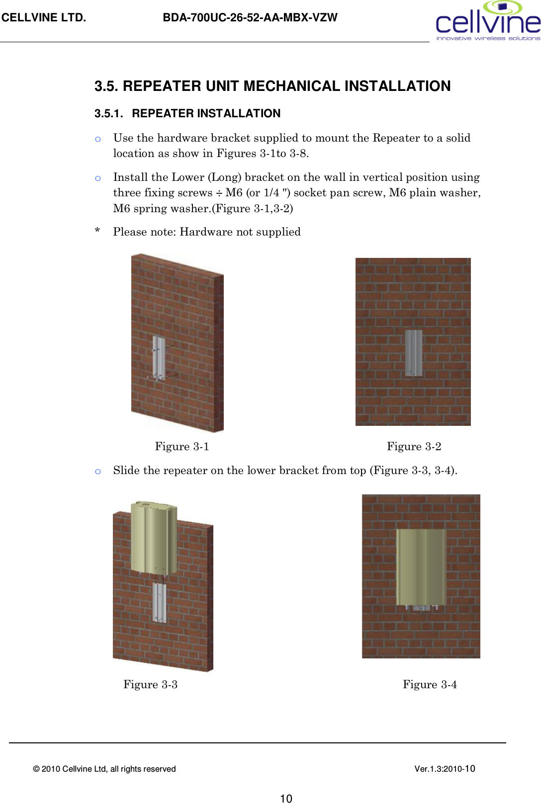
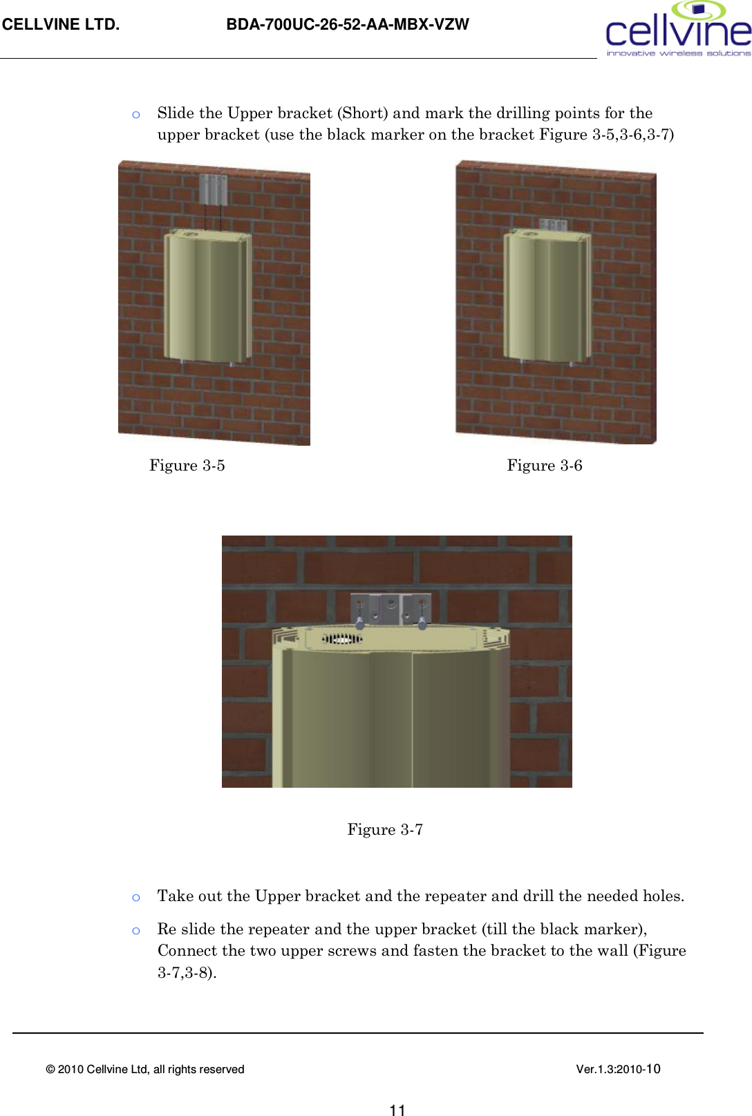
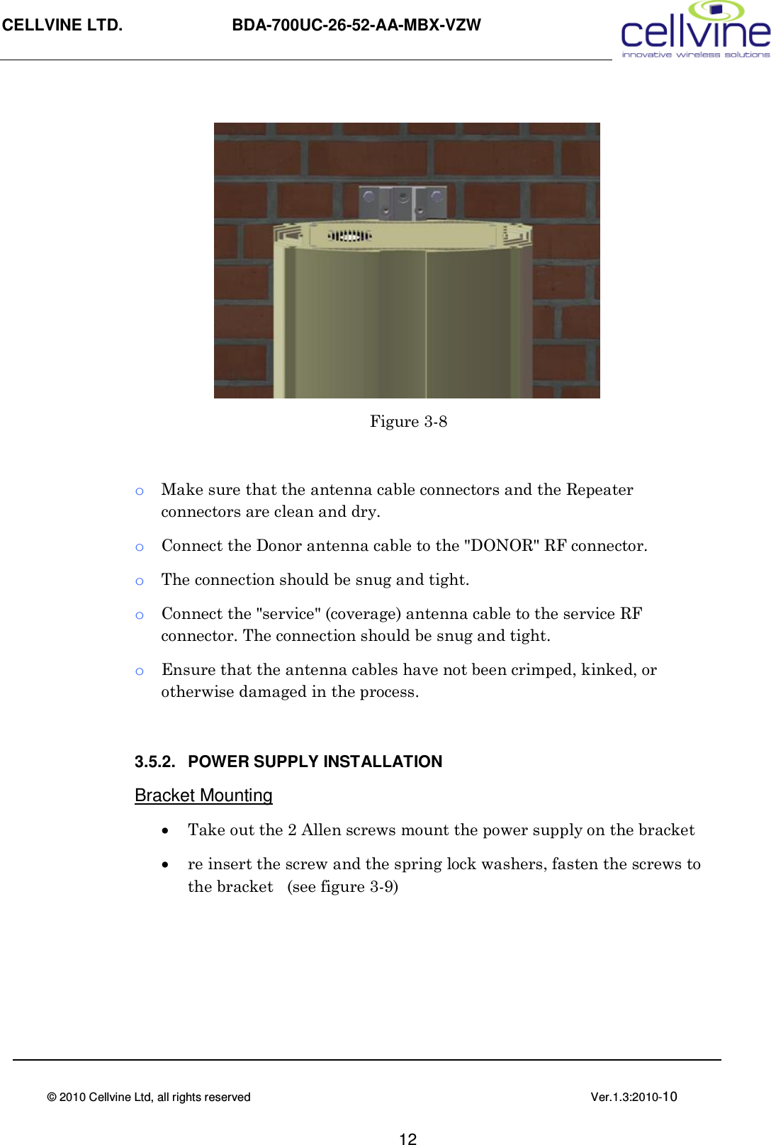
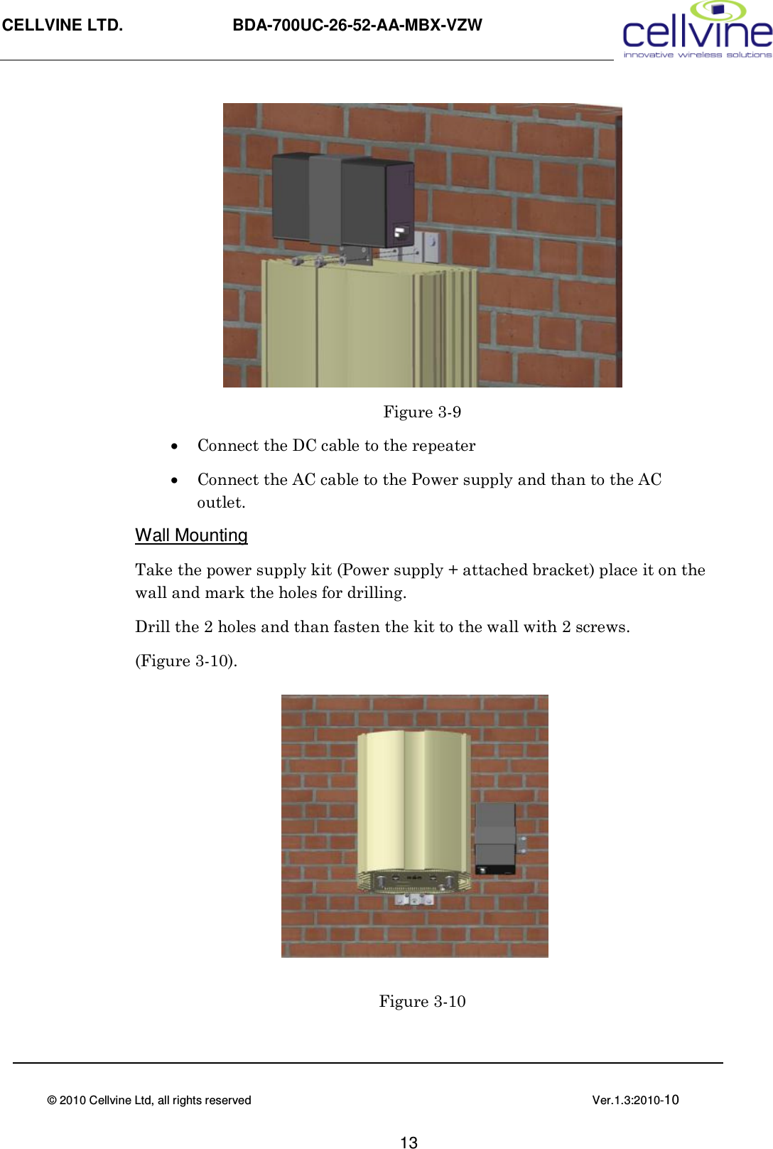
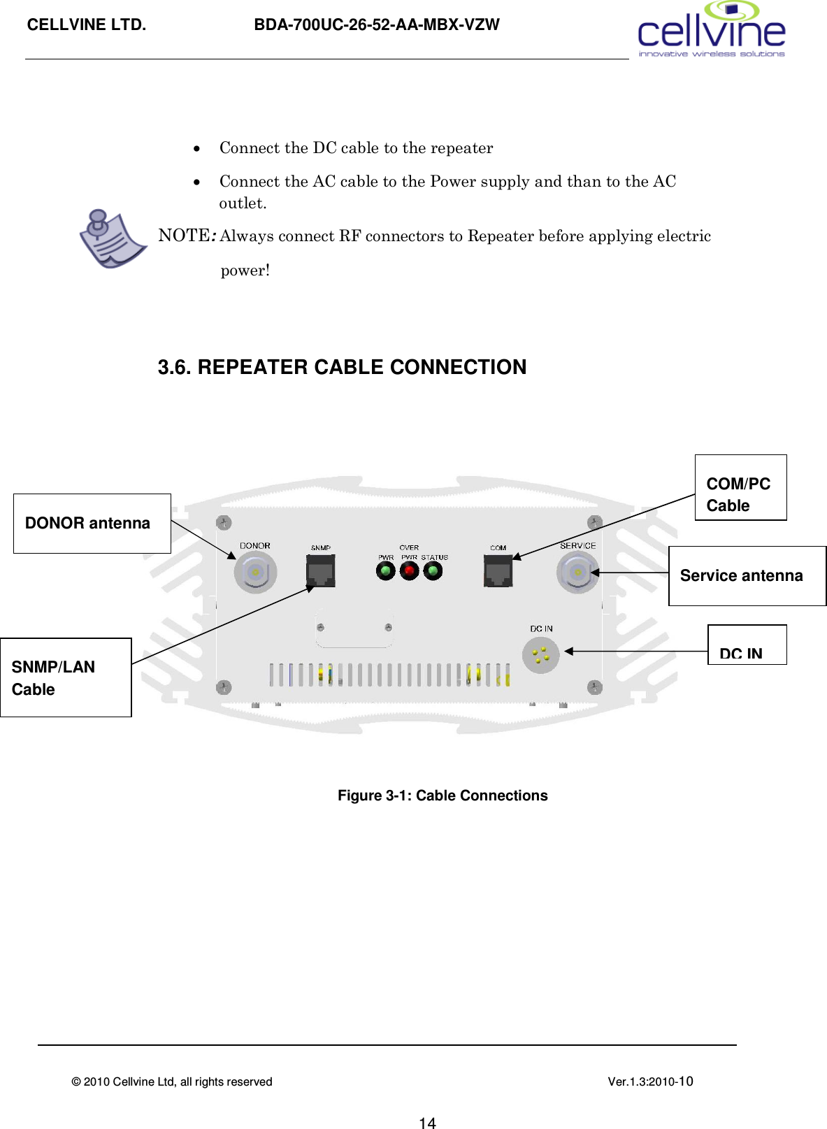
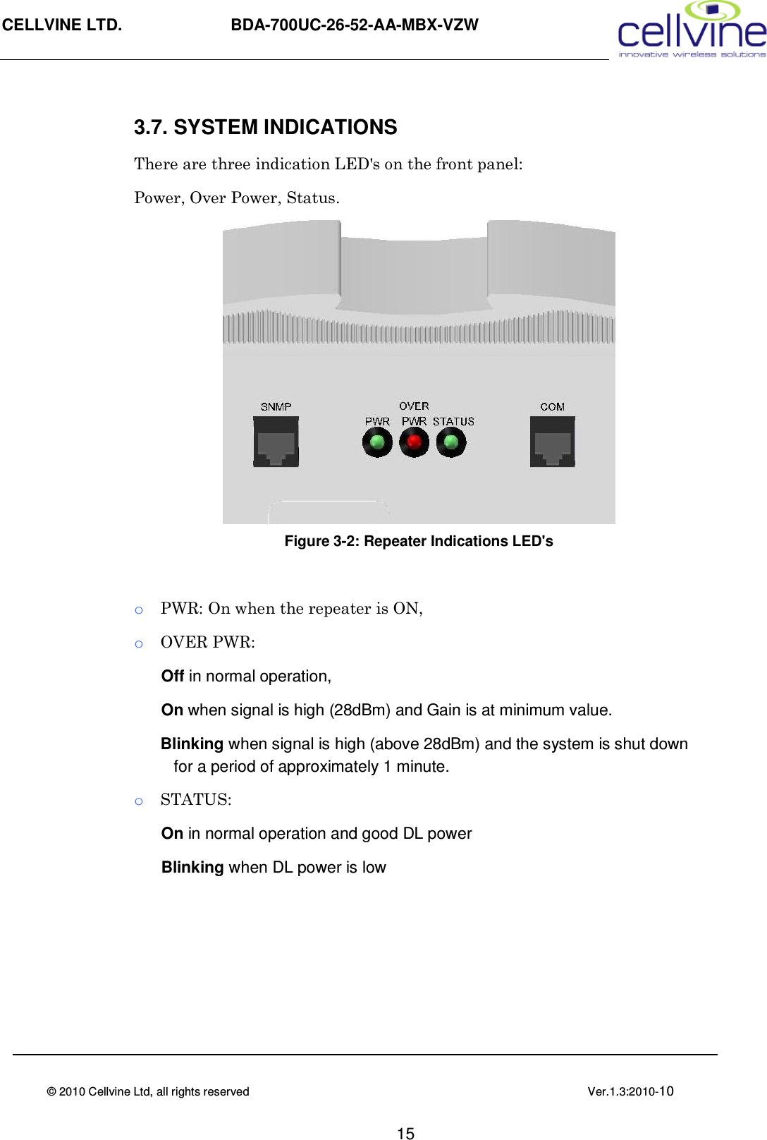
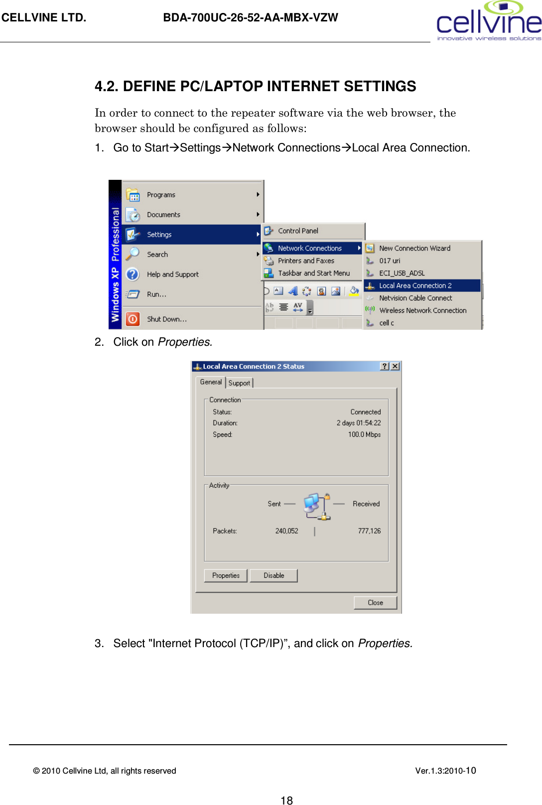
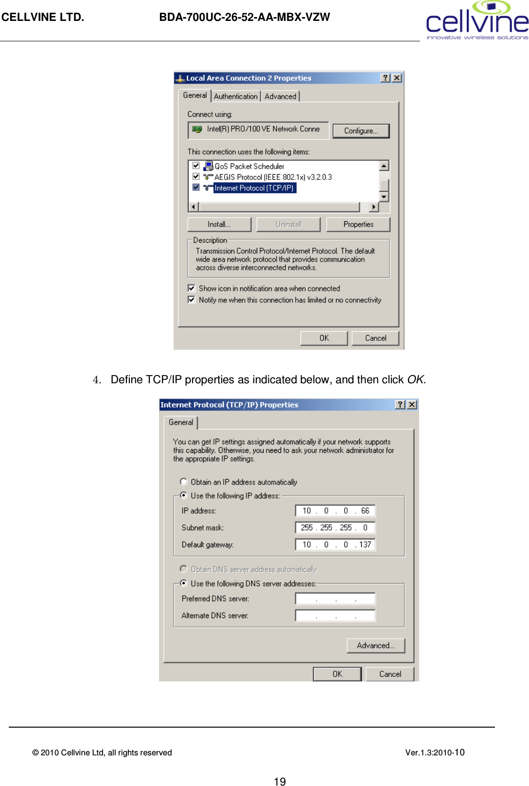
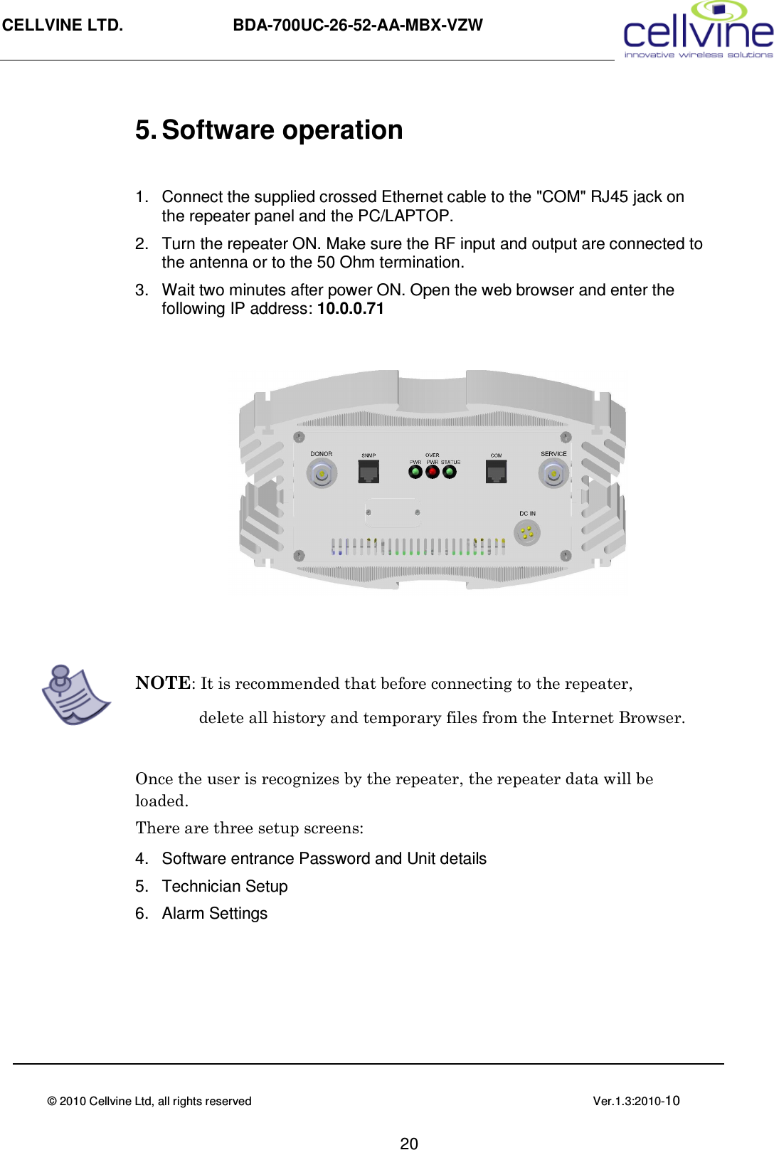
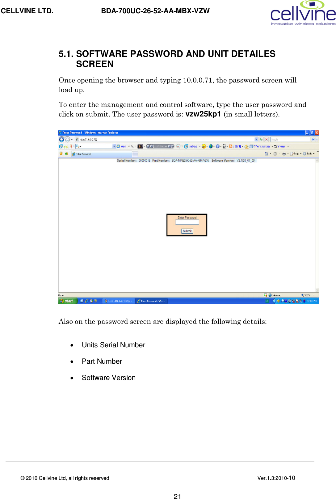
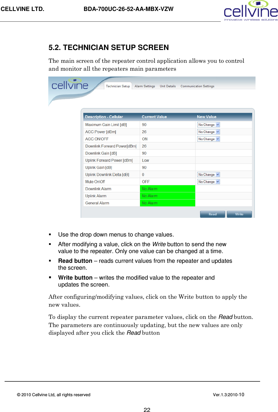
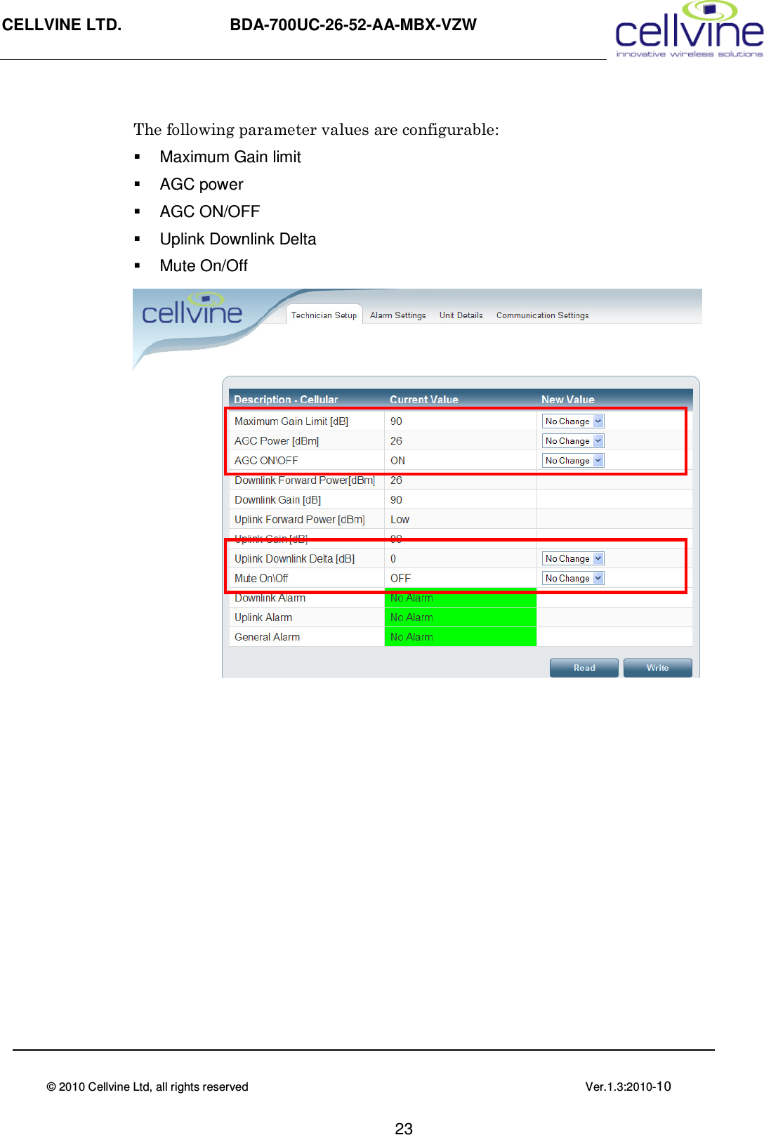
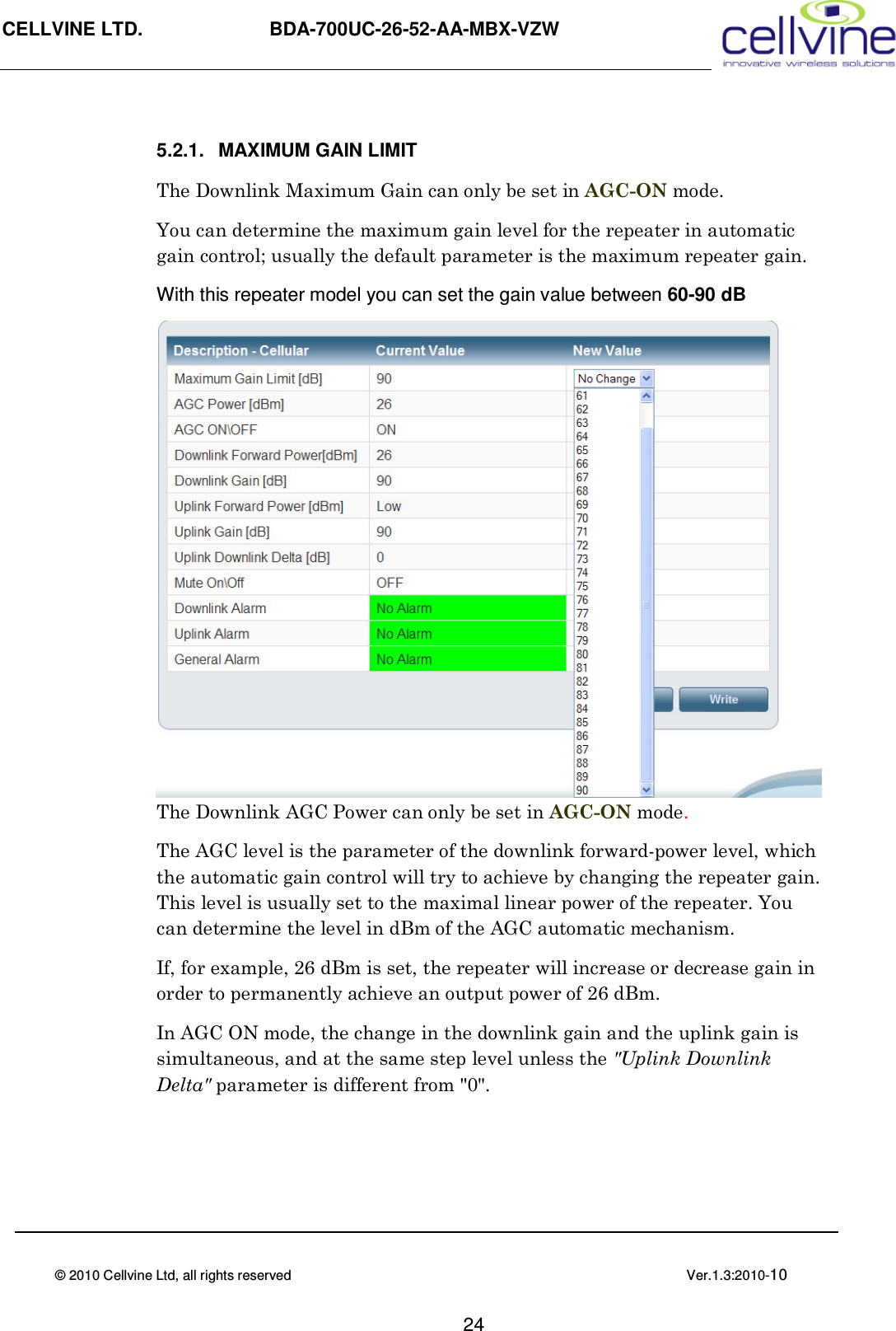
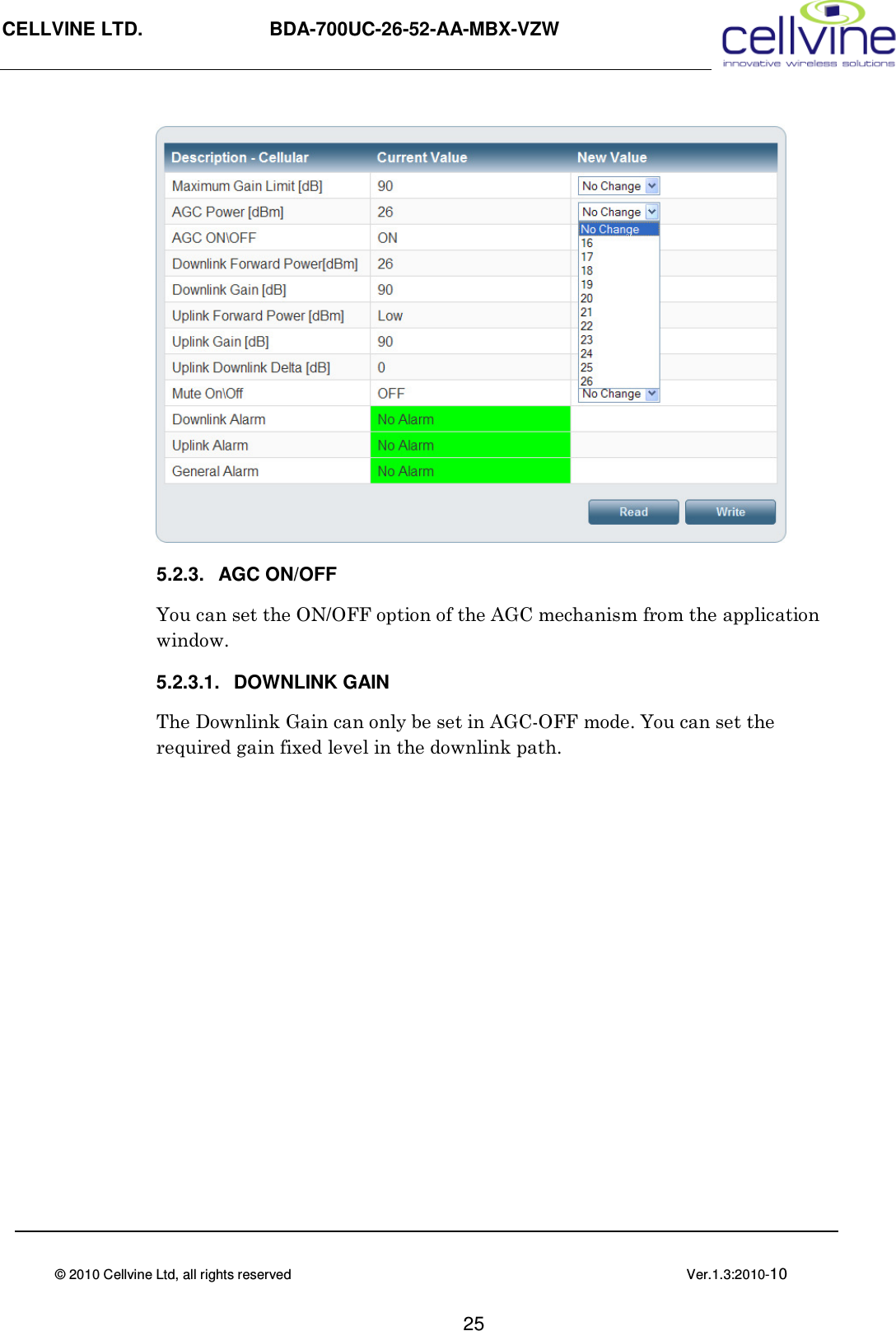
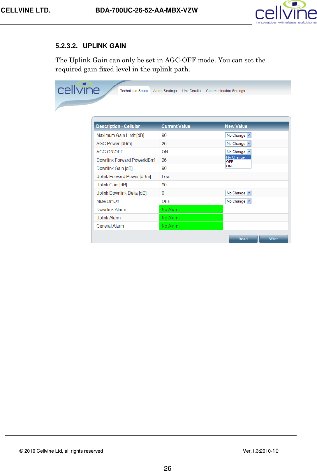
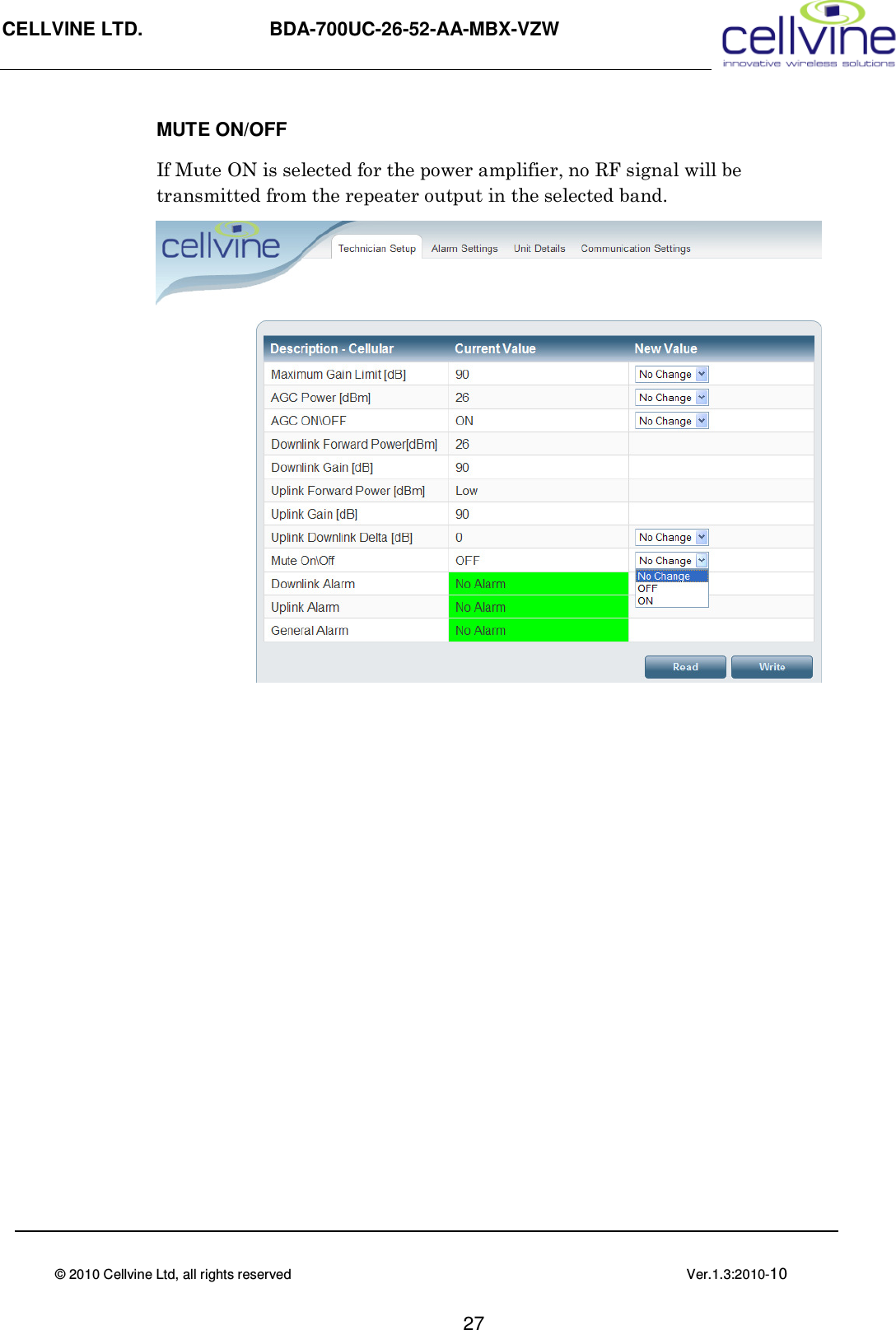
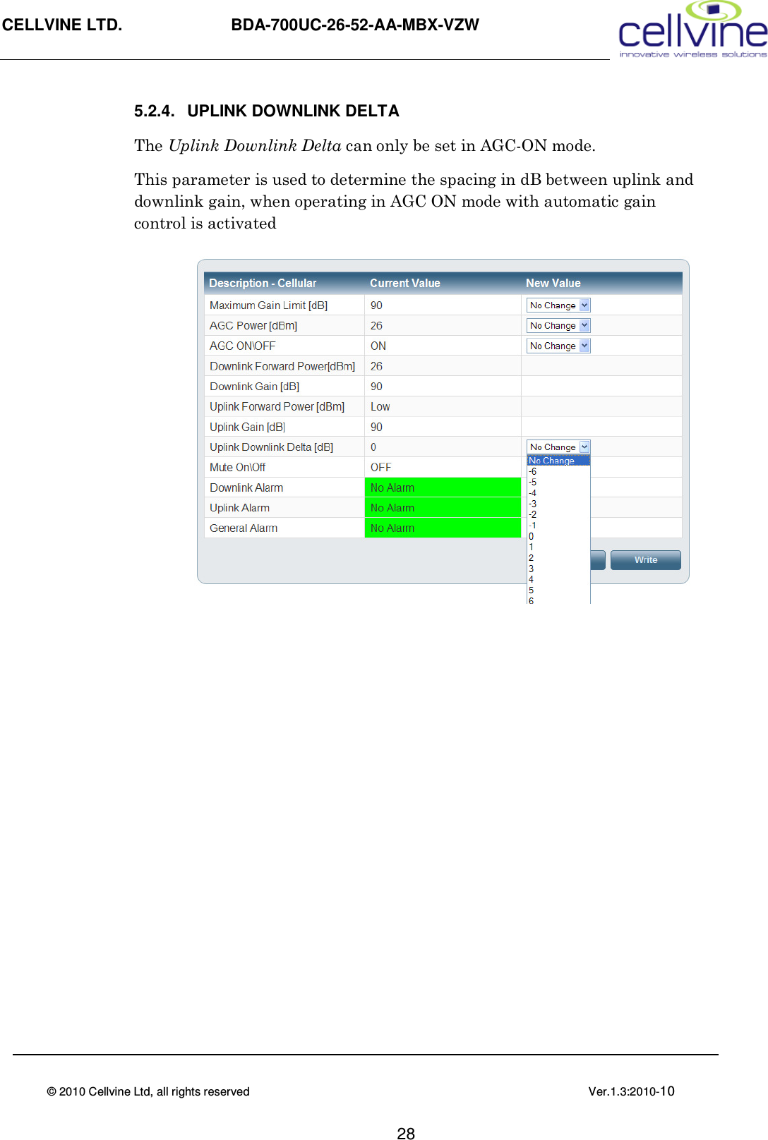
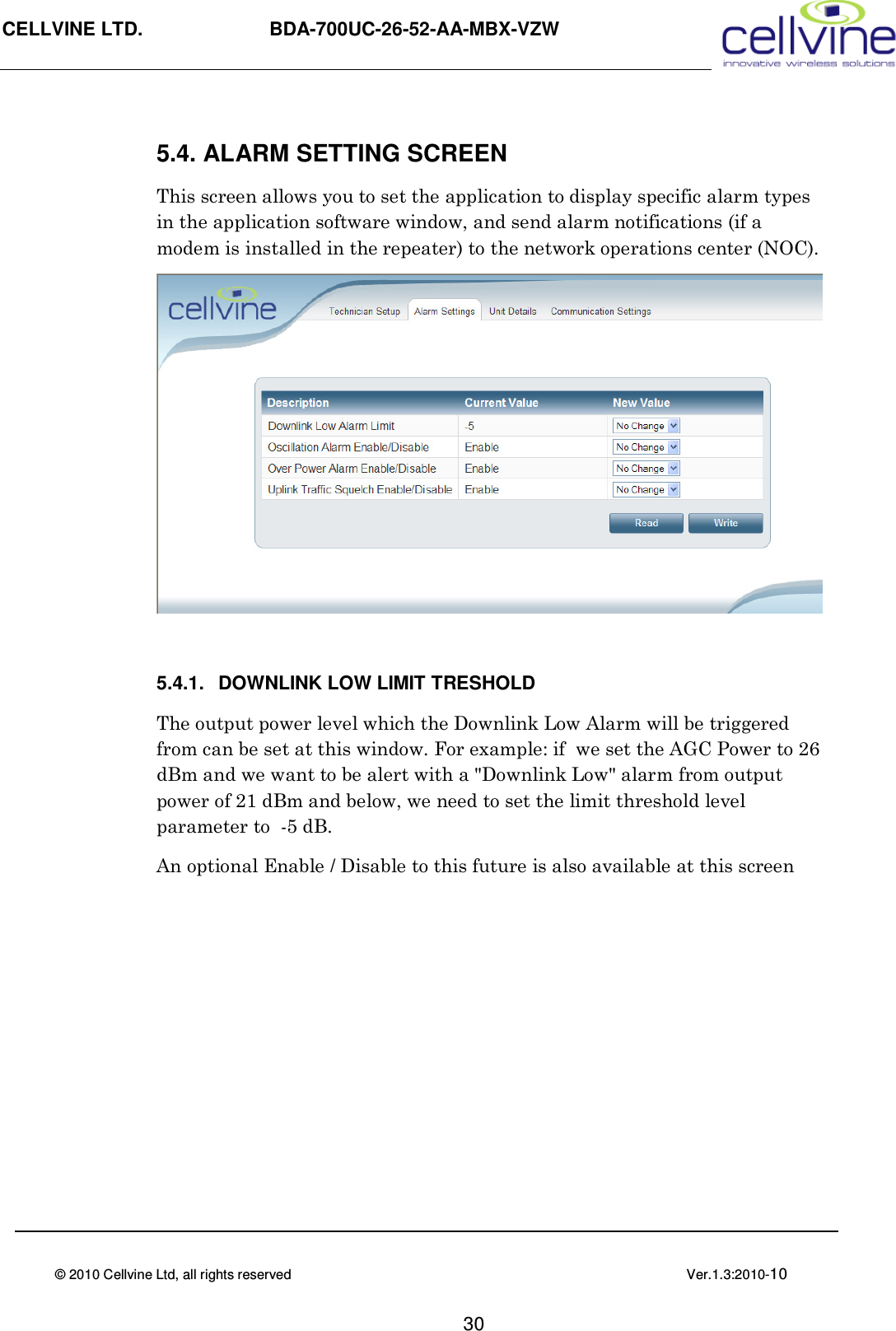
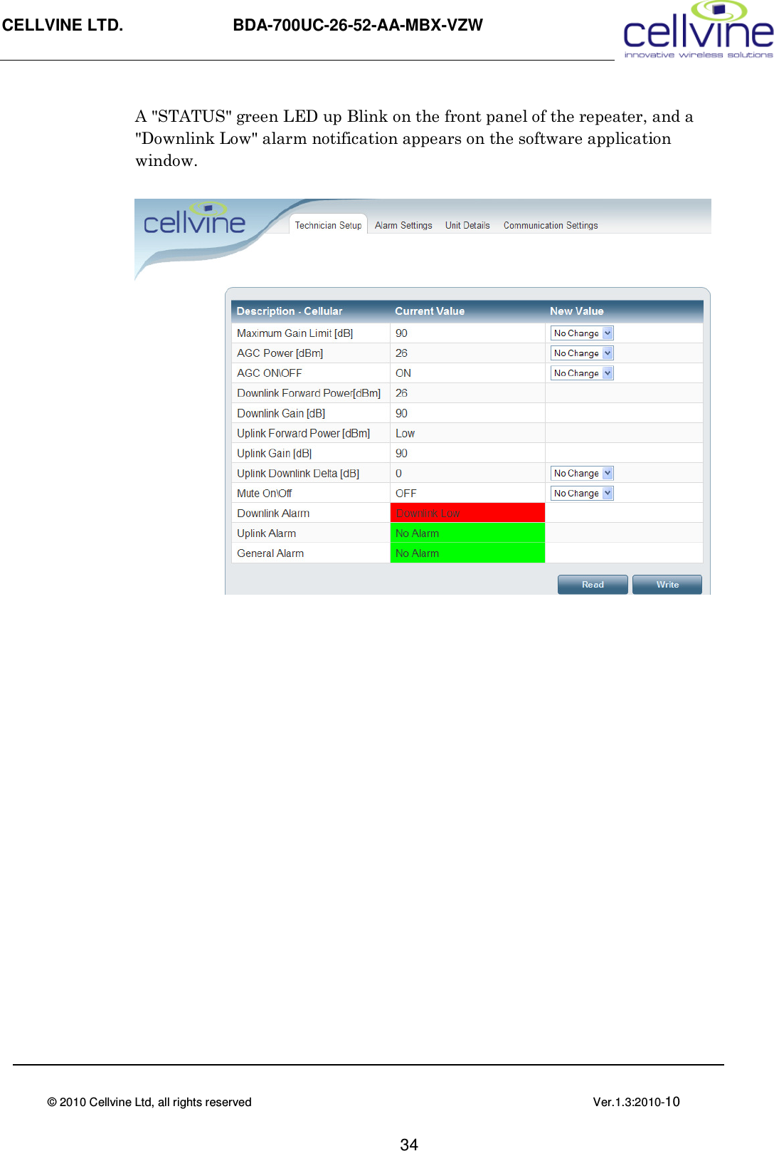
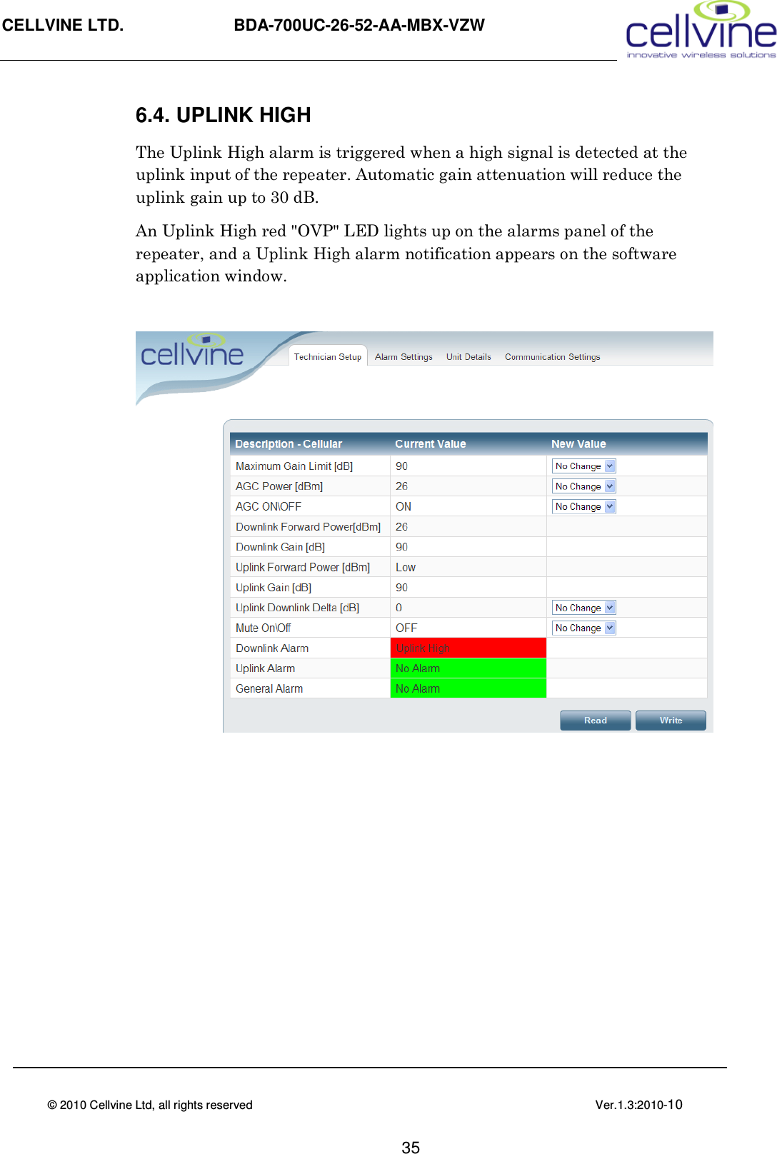
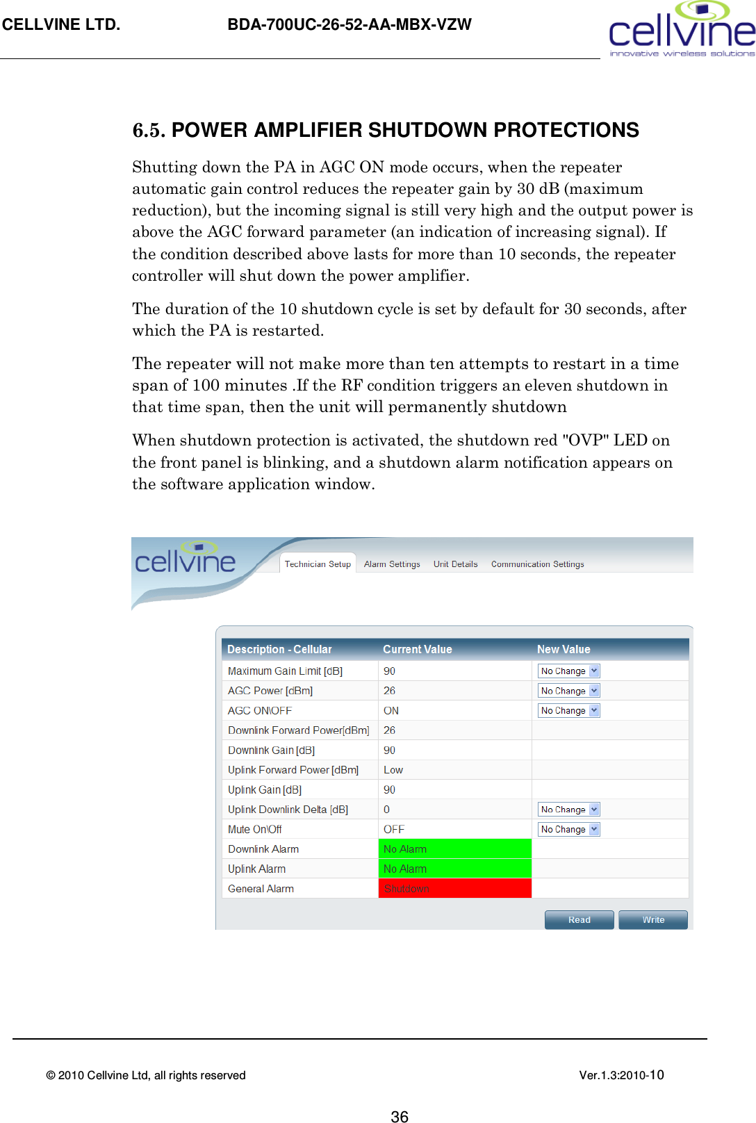
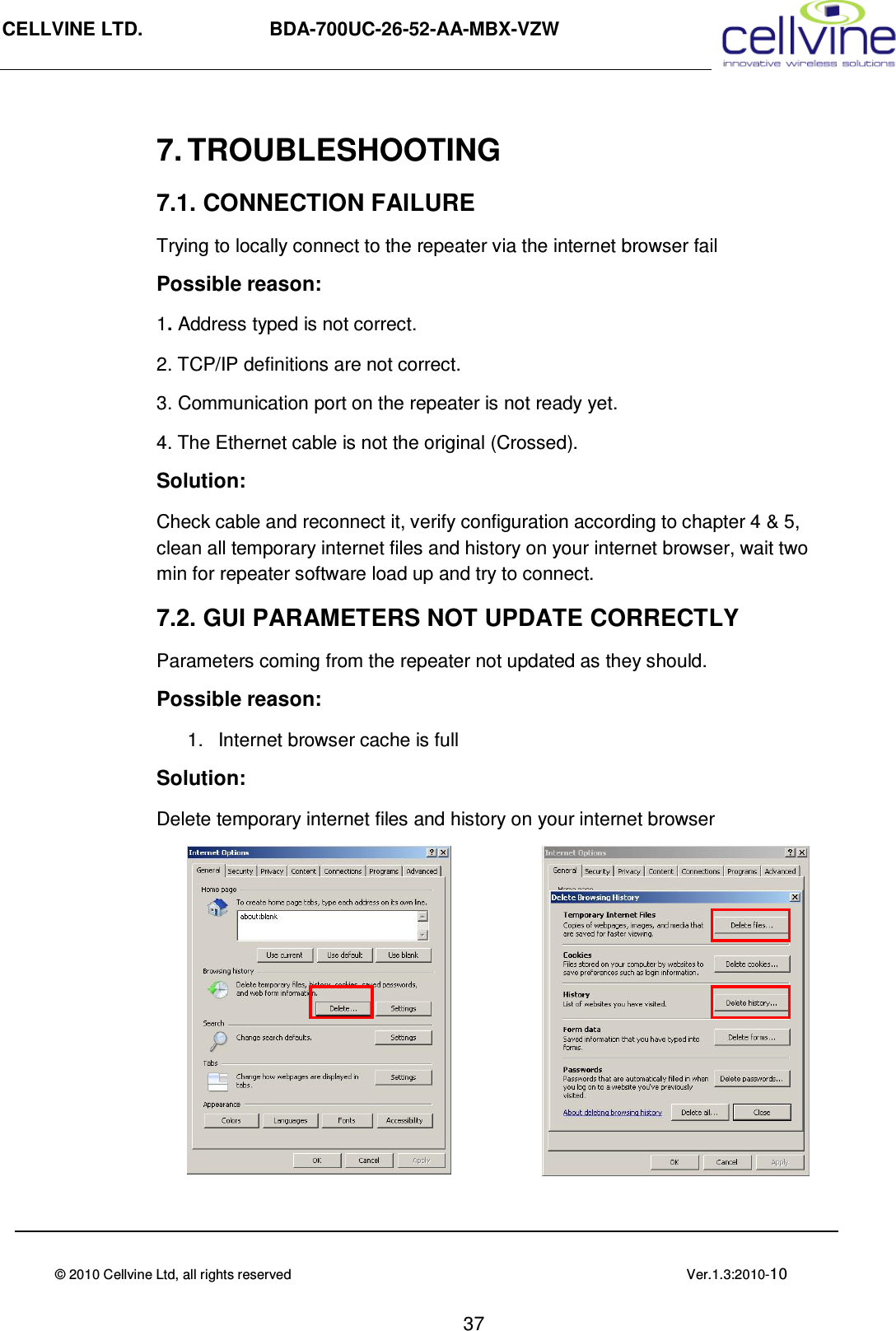
![CELLVINE LTD. BDA-700UC-26-52-AA-MBX-VZW © 2010 Cellvine Ltd, all rights reserved Ver.1.3:2010-10 29 5.3. PARAMETER VALUE READOUTS The parameter current values indicate the current repeater status. Downlink Forward Power [dBm]- Real time indication of the current forward (output) power of the repeater in each band, and the currently downlink gain. Downlink Gain [dB]- The current downlink Gain of the repeater, and changes in Gain according to the AGC level Uplink Forward Power [dBm] - Real time indication of the current reverse power of the BTS from the repeater in each band, and the currently downlink gain. Uplink Gain [dB] - The current Uplink Gain of the repeater, and changes in Gain according to the AGC level](https://usermanual.wiki/Cellvine/LTE700UC26/User-Guide-1385697-Page-40.png)