Cellvine TDDMR2516 TDD Mini Repeater User Manual Type SRS SDD
Cellvine Ltd. TDD Mini Repeater Type SRS SDD
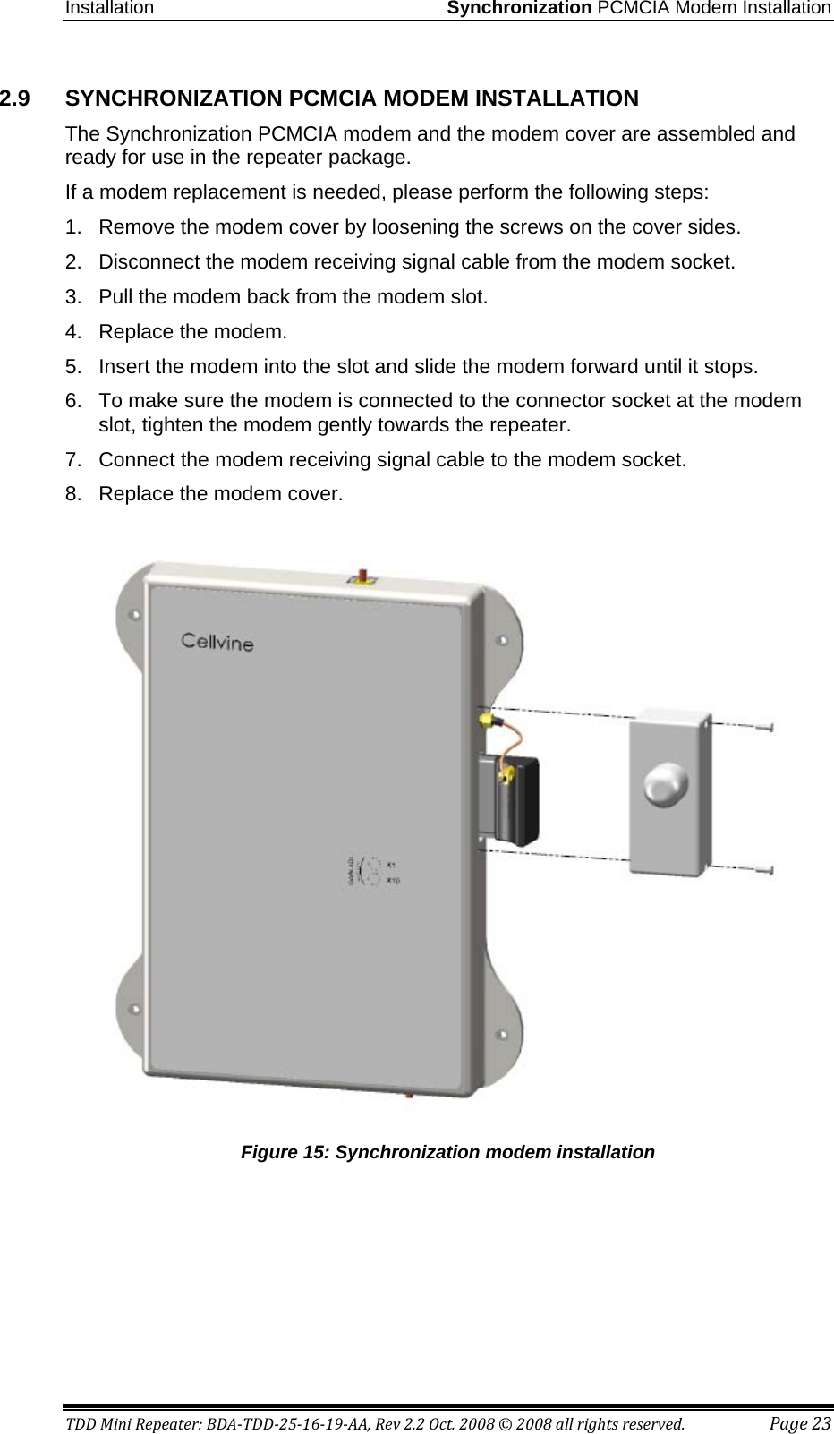
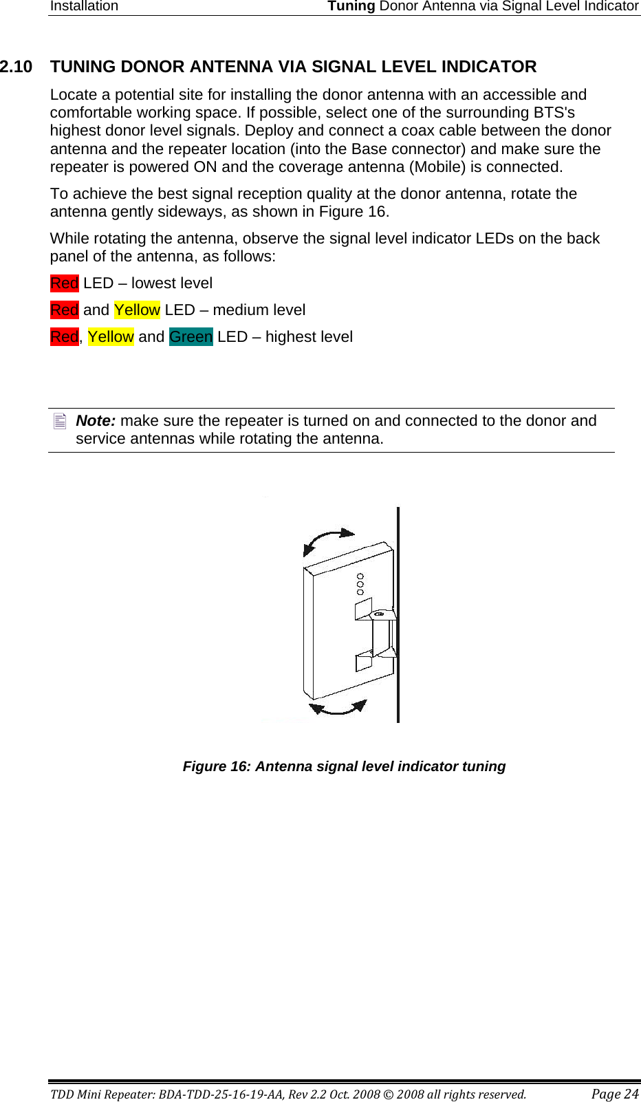
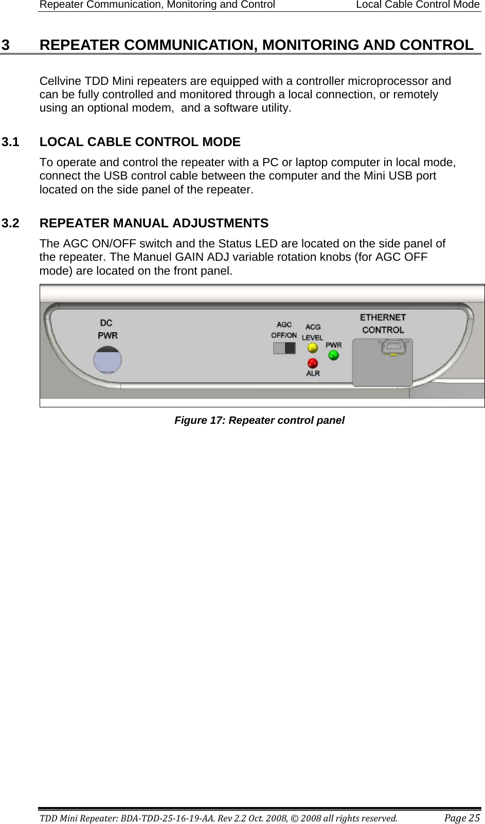
UserManual.wiki
>
Cellvine
>
TDDMR2516 User Manual
User Manual
Navigation menu
Upload a User Manual
Namespaces
Wiki Guide
HTML
PDF
Info
Views
User Manual
Discussion / Help
Navigation
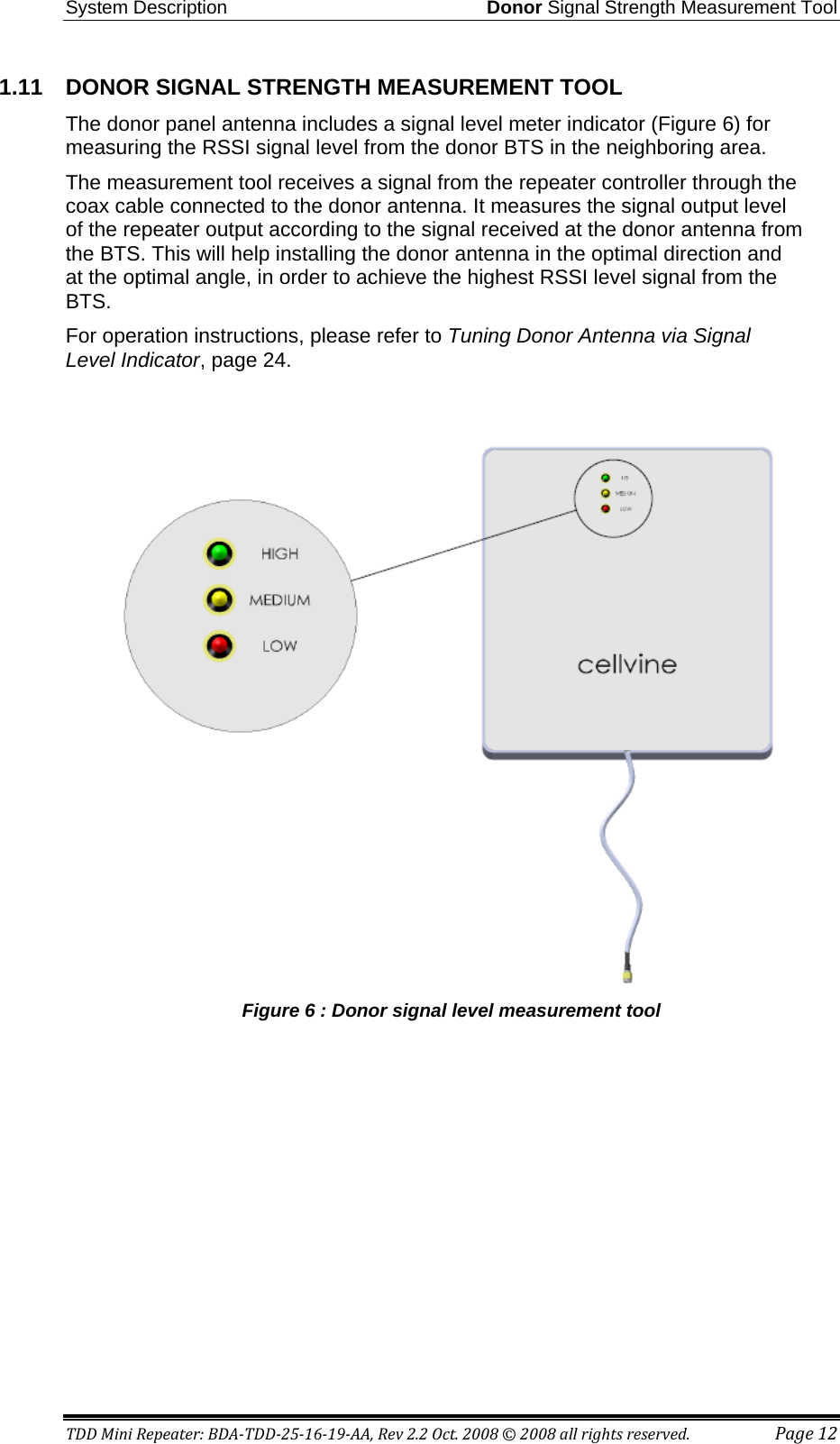
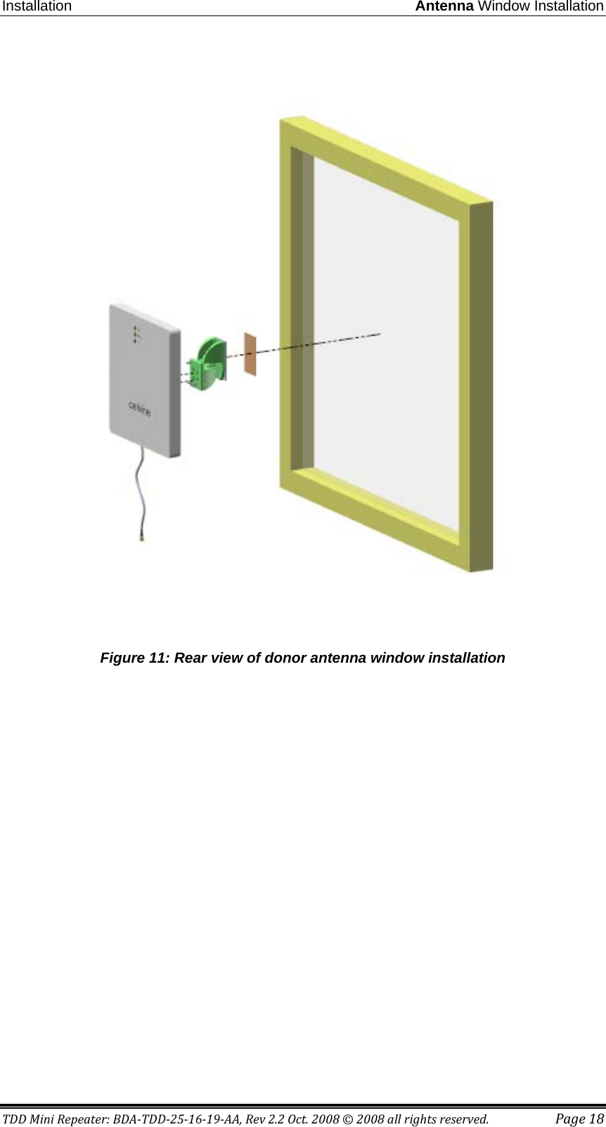
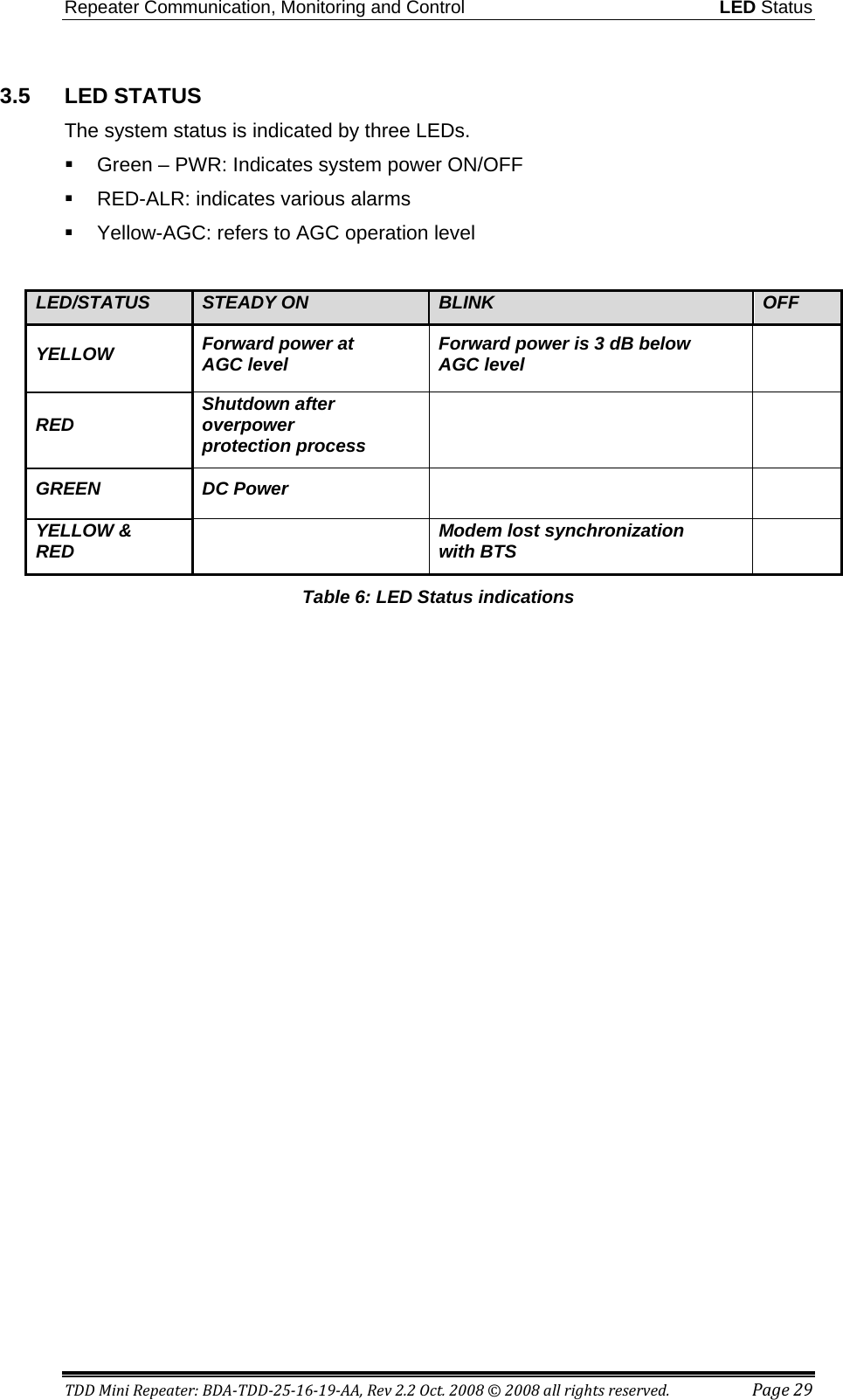
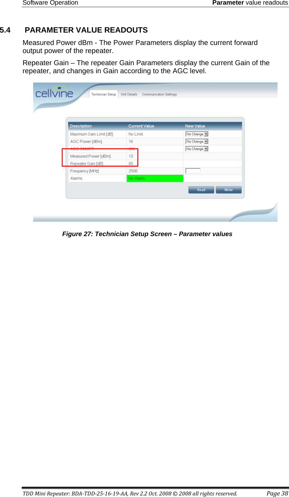
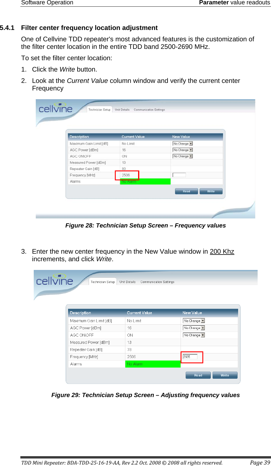
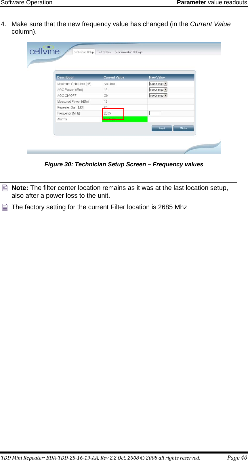
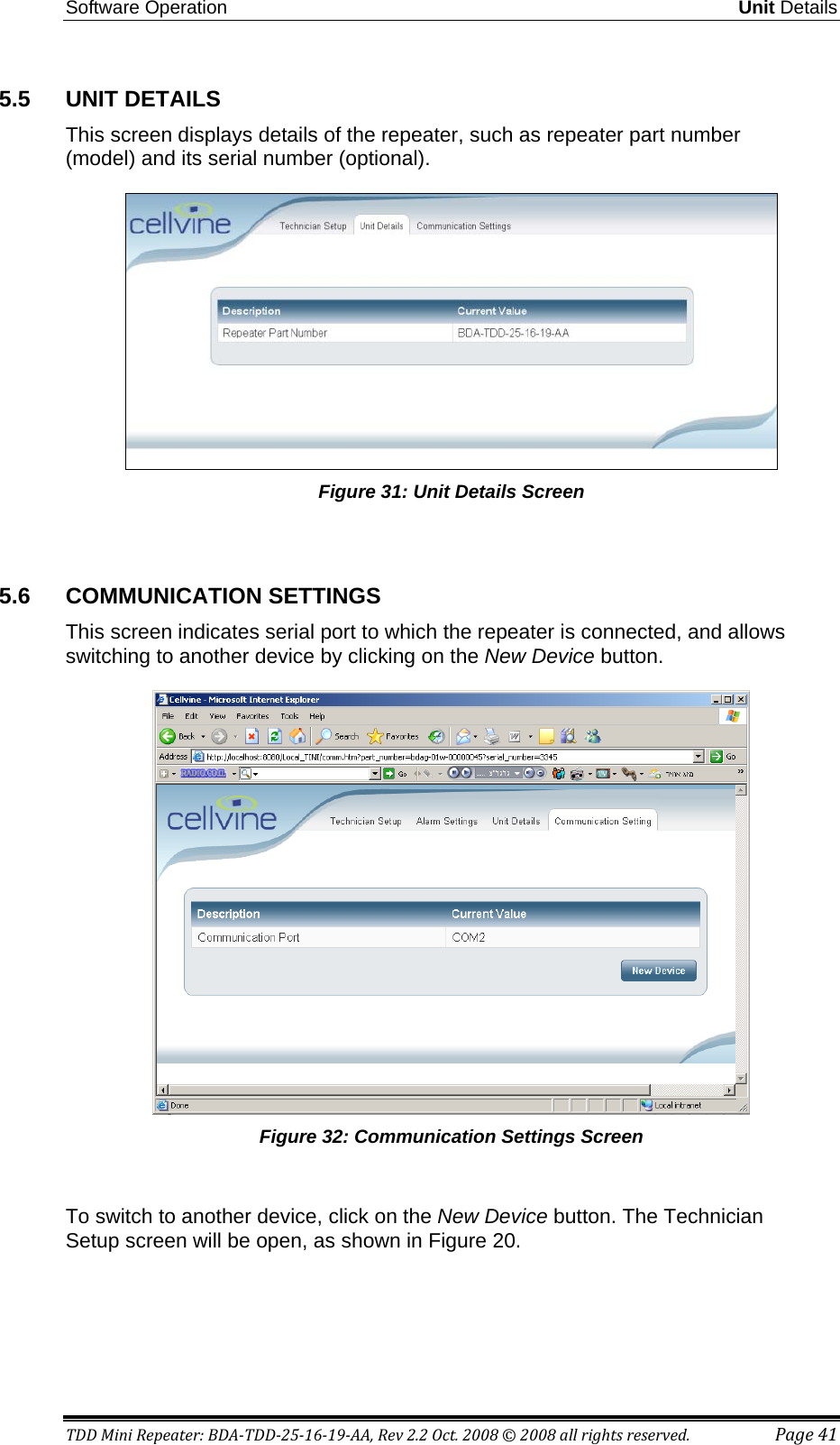
![System Description Donor Signal Strength Measurement Tool TDD Mini Repeater: BDA-TDD-25-16-19-AA, Rev 2.2 Oct. 2008 © 2008 all rights reserved. Page 13 1.11.1 Indoor Omni Coverage Antenna Specifications Electrical Specifications Frequency Range 2300-2700MHz VSWR ≤2.0 Input Impedance 50Ω Gain 3dBi Polarization Vertical Maximum Input Power 50W Connector Type SMA -Male Lightning Protection DC ground Mechanical Specifications Height 105mm Weight 62g Cable Length 3m Antenna Color Black Working Temperature -40~140 0F Table 4 : Indoor Omni coverage antenna specification 1.11.2 Adhesive tape specifications and installation recommendation for the antenna mounting bracket After application, the bond strength will increase as the adhesive flows onto the surface. At room temperature approximately 50% of ultimate bond strength will be achieved after 20 minutes, 90% after 24 hours and 100% after 72 hours. This flow is faster at higher temperatures and slower at lower temperatures. Ultimate bond strength can be achieved more quickly (and in some cases bond strength can be increased) by exposure of the bond to elevated temperatures (e.g. 150°F [66°C] for 1 hour). This can provide better adhesive without on to the substrates. Abrasion of the surfaces or the use of primers/ adhesion promoters can also have the effect of increasing bond strength and achieving ultimate bond strength more quickly.](https://usermanual.wiki/Cellvine/TDDMR2516/User-Guide-1013745-Page-21.png)