Cellvine TDDMR2516 TDD Mini Repeater User Manual Type SRS SDD
Cellvine Ltd. TDD Mini Repeater Type SRS SDD
Cellvine >
User Manual
REV 2.2 October 2008
Doc. No. NGC10100
BDA-TDD-25-16-19-AA
TDD Mini Repeater
General Installation & Operation Guide

Revisions
TDD Mini Repeater: BDA-TDD-25-16-19-AA. Rev 2.2, Oct. 2008. © 2008 all rights reserved.
REVISIONS
Rev
Description of Change
Revision date
Revised by
2.0
General update-according to NGC review
16.9.2008
Cellvine-Ziv Shani
2.1
General update-according to NGC review
28.9.2008
Cellvine-Ziv Shani
2.2
FCC Statement and donor antenna spec.
02.10.2008
Cellvine-Ziv Shani
IMPORTANT NOTICE
This manual contains proprietary information of Cellvine Ltd. No part of this publication may be
reproduced in any form whatsoever without prior written approval of Cellvine Ltd. Cellvine and/or
its agents make no claims or warranties for fitness for any purpose other than what is specifically
mentioned in this manual is made either by Cellvine or its agents.
For further information contact Cellvine at the address below or contact your local distributor.
CELLVINE CONTACT INFORMATION
Headquarter:
Cellvine Ltd.
6 Yoni Netanyahu St.
Or-Yehuda, Israel 60376
Phone: +972-3-6348881
Fax: +972-3-6348882
U.S. Office:
Cellvine USA
63 Lake Ave Fair Haven,
NJ 07704
USA
Tel: +1 908 902 5890

Table of Contents
TDD Mini Repeater: BDA-TDD-25-16-19-AA, Rev 2.2 Oct. 2008. © 2008 all rights reserved. Page i
TABLE OF CONTENTS
1 SYSTEM DESCRIPTION ........................................................................................................... 1
1.1 INTRODUCTION .......................................................................................................................... 1
1.2 TDD REPEATER AND ANTENNA KIT ................................................................................................ 2
1.3 WHAT’S IN THE BOX - REPEATER ACCESSORIES ................................................................................. 3
1.4 INDOOR REPEATER ...................................................................................................................... 5
1.5 PREPARATION FOR INSTALLATION ................................................................................................... 5
1.6 REPEATER UNIT RF SPECIFICATIONS ............................................................................................... 6
1.7 REPEATER DIMENSIONS ............................................................................................................... 7
1.8 BRACKET DIMENSIONS ................................................................................................................. 8
1.9 REPEATER INTERFACES ................................................................................................................. 8
1.10 ANTENNAS ................................................................................................................................ 8
1.10.1 Donor Panel Antenna ........................................................................................................................ 9
1.11 DONOR SIGNAL STRENGTH MEASUREMENT TOOL ........................................................................... 12
1.11.1 Indoor Omni Coverage Antenna Specifications .............................................................................. 13
1.11.2 Adhesive tape specifications and installation recommendation for the antenna mounting bracket
........................................................................................................................................................ 13
2 INSTALLATION ..................................................................................................................... 14
2.1 UNPACKING AND INSPECTION ...................................................................................................... 14
2.2 ANTENNA INSTALLATION ............................................................................................................ 14
2.3 PRE-INSTALLATION INSPECTION ................................................................................................... 15
2.4 DONOR ANTENNA INSTALLATION ................................................................................................. 15
2.5 ANTENNA WINDOW INSTALLATION .............................................................................................. 15
2.6 DONOR ANTENNA WALL INSTALLATION ........................................................................................ 19
2.7 REPEATER UNIT MECHANICAL INSTALLATION ................................................................................. 21
2.8 CABLE AND MOUNTING INSTALLATION PRECAUTIONS ...................................................................... 22
2.9 SYNCHRONIZATION PCMCIA MODEM INSTALLATION ...................................................................... 23
2.10 TUNING DONOR ANTENNA VIA SIGNAL LEVEL INDICATOR ................................................................. 24
3 REPEATER COMMUNICATION, MONITORING AND CONTROL .............................................. 25
3.1 LOCAL CABLE CONTROL MODE .................................................................................................... 25
3.2 REPEATER MANUAL ADJUSTMENTS .............................................................................................. 25
3.3 REPEATER AGC ON - OPERATION MODE ...................................................................................... 26
3.4 AGC OFF-OPERATION MODE .................................................................................................... 26
3.4.1 Using the Variable Rotation Knobs in AGC OFF Mode .................................................................... 27
3.4.2 Setting the Gain in Manual Adjustment – AGC OFF Mode ............................................................. 28
3.5 LED STATUS ............................................................................................................................ 29
4 SOFTWARE INSTALLATION .................................................................................................. 30
4.1 SYSTEM REQUIREMENTS ............................................................................................................ 30
4.2 INSTALLING THE SOFTWARE ........................................................................................................ 30

Table of Contents
TDD Mini Repeater: BDA-TDD-25-16-19-AA, Rev 2.2 Oct. 2008. © 2008 all rights reserved. Page ii
4.3 USB DRIVER INSTALLATION ........................................................................................................ 30
5 SOFTWARE OPERATION ....................................................................................................... 33
5.1 TECHNICIAN SETUP SCREEN ......................................................................................................... 33
5.2 READ AND WRITE PARAMETERS .................................................................................................... 34
5.3 TECHNICIEN SETUP - VARIABLE PARAMETER DESCRIPTION ................................................................. 35
5.3.1 Maximum Gain Limit ....................................................................................................................... 35
5.3.2 AGC Power ...................................................................................................................................... 36
5.3.3 AGC ON/OFF ................................................................................................................................... 37
5.3.4 Repeater Gain ................................................................................................................................. 37
5.4 PARAMETER VALUE READOUTS .................................................................................................... 38
5.4.1 Filter center frequency location adjustment .................................................................................. 39
5.5 UNIT DETAILS .......................................................................................................................... 41
5.6 COMMUNICATION SETTINGS ....................................................................................................... 41
6 ALARMS AND PROTECTION MECHANISMS .......................................................................... 42
6.1 LOW SIGNAL ALARM ................................................................................................................. 42
6.2 OVER-POWER ALARM - HIGH SIGNAL PROTECTION .......................................................................... 43
6.3 POWER AMPLIFIER SHUTDOWN PROTECTION ................................................................................. 44
6.4 SYNCHRONIZATION PCMCIA MODEM ......................................................................................... 44
6.5 ALARM LEDS INDICATIONS ......................................................................................................... 45
6.6 EXITING THE PROGRAM .............................................................................................................. 46
Figures
FIGURE 1: REPEATER DIMENSION ........................................................................................................................... 7
FIGURE 2: BRACKET DIMENSIONS ........................................................................................................................... 8
FIGURE 3: DONOR PANEL ANTENNA DIMENSION IN INCHES ....................................................................................... 9
FIGURE 4: DONOR PANEL ANTENNA DIMENSION IN INCHES WITH FRONT WINDOW BRACKET ...................................... 10
FIGURE 5: DONOR ANTENNA HORIZONTAL RADIATION PATTERN .............................................................................. 11
FIGURE 6 : DONOR SIGNAL LEVEL MEASUREMENT TOOL ......................................................................................... 12
FIGURE 7: INSTALLING DONOR ANTENNA ON WINDOW ............................................................................................ 16
FIGURE 8: CONNECTING ANTENNA HOLDER TO ANTENNA ADAPTOR ........................................................................ 16
FIGURE 9: FRONT VIEW OF DONOR INSTALLATION ON WINDOW GLASS – CORRECT INSTALLATION ............................ 17
FIGURE 10: WRONG INSTALLATION ...................................................................................................................... 17
FIGURE 11: REAR VIEW OF DONOR ANTENNA WINDOW INSTALLATION ..................................................................... 18
FIGURE 12: DONOR ANTENNA WALL BRACKET ASSEMBLY .................................................................................... 19
FIGURE 13 : DONOR ANTENNA WALL INSTALLATION ............................................................................................... 20
FIGURE 14: REPEATER WALL INSTALLATION .......................................................................................................... 21
FIGURE 15: SYNCHRONIZATION MODEM INSTALLATION .......................................................................................... 23
FIGURE 16: ANTENNA SIGNAL LEVEL INDICATOR TUNING ........................................................................................ 24
FIGURE 17: REPEATER CONTROL PANEL .............................................................................................................. 25
FIGURE 18: ROTATE KNOB SETUP POSITION .......................................................................................................... 27
FIGURE 19: AGC OFF GAIN ATTENUATORS VARIABLE ROTATION KNOB ................................................................. 28
FIGURE 20: TECHNICIAN SETUP SCREEN ............................................................................................................. 33
FIGURE 21: TECHNICIAN SETUP SCREEN – READ/WRITE BUTTONS ........................................................................ 34
FIGURE 22: TECHNICIAN SETUP SCREEN –NEW VALUE FIELDS .............................................................................. 35
FIGURE 23: TECHNICIAN SETUP SCREEN – GAIN LIMIT SETUP ............................................................................... 35
FIGURE 24: TECHNICIAN SETUP SCREEN –AGC SETUP ........................................................................................ 36
FIGURE 25: TECHNICIAN SETUP SCREEN –AGC ON/OFF SETUP ........................................................................... 37

Table of Contents
TDD Mini Repeater: BDA-TDD-25-16-19-AA, Rev 2.2 Oct. 2008. © 2008 all rights reserved. Page iii
FIGURE 26: TECHNICIAN SETUP SCREEN –FIXED GAIN SETUP ............................................................................... 37
FIGURE 27: TECHNICIAN SETUP SCREEN – PARAMETER VALUES ........................................................................... 38
FIGURE 28: TECHNICIAN SETUP SCREEN – FREQUENCY VALUES ........................................................................... 39
FIGURE 29: TECHNICIAN SETUP SCREEN – ADJUSTING FREQUENCY VALUES .......................................................... 39
FIGURE 30: TECHNICIAN SETUP SCREEN – FREQUENCY VALUES ........................................................................... 40
FIGURE 31: UNIT DETAILS SCREEN ...................................................................................................................... 41
FIGURE 32: COMMUNICATION SETTINGS SCREEN ................................................................................................. 41
FIGURE 33: LOW SIGNAL ALARM .......................................................................................................................... 42
FIGURE 34: OVERPOWER ALARM ......................................................................................................................... 43
FIGURE 35: LOST SYNC ALARM ............................................................................................................................ 44
Tables
TABLE 1: REPEATER TECHNICAL SPECIFICATIONS ................................................................................................... 6
TABLE 2: REPEATER INTERFACES .......................................................................................................................... 8
TABLE 3: PANEL DONOR ANTENNA UNIT SPECIFICATIONS ....................................................................................... 10
TABLE 4 : INDOOR OMNI COVERAGE ANTENNA SPECIFICATION ............................................................................... 13
TABLE 5: SETTING THE GAIN IN MANUAL ADJUSTMENT – AGC OFF MODE ............................................................... 28
TABLE 6: LED STATUS INDICATIONS .................................................................................................................... 29
TABLE 7: ALARM LEDS INDICATIONS .................................................................................................................... 45

About this Document
TDD Mini Repeater: BDA-TDD-25-16-19-AA, Rev 2.2 Oct. 2008. © 2008 all rights reserved. Page iv
ABOUT THIS DOCUMENT
This document provides information about the installation and setup of the Cellvine repeaters.
The information consists of procedures for unpacking, inspection and preparation for the
installation, and the actual installation and setup. It is important to install the repeater correctly at
its working location. It is recommended that installation be performed by a certified radio
technician.
The repeater installation consists of four basic steps:
1. Antenna installation
2. Repeater installation
3. Cable installation
4. Repeater parameters setup and tuning using the supplied dedicated application
TERMS AND ABBREVIATIONS
The terms, acronyms and abbreviations used in this manual are detailed in the following list:
Abbreviation Des cription
AGC
Automatic Gain Control
BDA
Bi Directional Amplifier
BL
Bluetooth
Div
Diversity
DA
Donor Antenna Unit
LED
Light Emitting Diode
LNA
Low Noise Amplifier
NMS
Network Management System
PA
Power Amplifier
PSU
Power Supply Unit
REP
repeater
RF
Radio Frequency
RSSI
Received Signal Strength Indication
RU
Remote Unit
RX
Receiver
SC
Service Channel
TX
Transceiver Unit
SYMO
Synchronization Modem
General Safety Warnings
TDD Mini Repeater: BDA-TDD-25-16-19-AA, Rev 2.2 Oct. 2008. © 2008 all rights reserved. Page v
GENERAL SAFETY WARNINGS
Always observe standard safety precautions during installation, operation and maintenance of
this product. Only qualified and authorized personnel should carry out adjustment, maintenance
or repairs to the components of this system.
Danger: Electrical Shock
The power supply unit contains dangerous voltage that can cause electric shock.
Disconnect the mains prior to any work in the repeater. Any local regulations are to be
followed when servicing repeaters.
This equipment is usually installed indoors. Wet conditions increase the potential for
receiving an electric shock when installing or using electrically powered equipment. To
prevent electrical shock when installing or modifying the system power wiring,
disconnect the wiring at the power source before working with insinuated wires or
terminals.
Repeaters supplied from the mains must be connected to grounded outlets and in
conformity with any local regulations.
Caution: High Ground
When working on a repeater on high ground, e.g. on a mast or pole, be careful not to
drop parts or the entire repeater. Falling parts can cause serious personal injury.
Caution: Coax Cable Bending
Allow sufficient coax cable length to permit routing of patch cords or pigtails without
severe bends.
Caution: Static Electricity
Static electricity poses no risk of personal injury, but it can severely damage essential
parts of the repeater, if not handled carefully.
Parts of the printed circuit board as well as other parts of the repeater are sensitive to
electrostatic discharge.
Never touch the printed circuit board or annulated conductor surfaces unless absolutely
necessary.
If you must handle the printed circuit board or uninsulated conductor surfaces, use ESD
protective equipment, or first touch the repeater chassis with your hand and then do not
move your feet on the floor.
Never let your clothes touch printed circuit boards or uninsulated conductor surfaces.
Always store printed circuit boards in ESD-safe bags.
Maximum input power at Base Port is - 40 dBm in AGC ON mode.

FCC Statement
TDD Mini Repeater: BDA-TDD-25-16-19-AA, Rev 2.2 Oct. 2008. © 2008 all rights reserved. Page vi
FCC STATEMENT
This equipment has been tested and found to comply with the limits for a Class A digital
device, pursuant to part 15 of the FCC Rules. These limits are designed to provide
reasonable protection against harmful interference when the equipment is operated in a
commercial environment. This equipment generates, uses, and can radiate radio
frequency energy and, if not installed and used in accordance with the instruction manual,
may cause harmful interference to radio communications. Operation of this equipment in a
residential area is likely to cause harmful interference, in which case the user will be
required to correct the interference at his expense. Changes or modifications not
expressly approved by the party responsible for compliance could void the user’s authority
to operate the equipment.
RF exposure warning! In order to comply with FCC RF exposure regulations, you must
ensure that the donor antenna is installed at a minimum distance of 0.2 m (7.8 inches) from
persons who may be present in the area. For more information please see Antenna Window
Installation, page 15.

System Description Introduction
TDD Mini Repeater: BDA-TDD-25-16-19-AA. Rev 2.2 Oct. 2008, © 2008 all rights reserved. Page 1
1 SYSTEM DESCRIPTION
1.1 INTRODUCTION
The TDD Mini repeater system is designed to improve coverage for customers
using TDD broadband 2500-2700 Mhz in medium size indoor areas.
The system implements BDA technology to enhance coverage in urban areas.
Repeaters are used to fill out uncovered areas in cellular mobile systems, such
as base station fringe areas, road tunnels, business and industrial buildings, etc.
A repeater receives signals from a base station, amplifies the signals and
retransmits them to mobile stations. It also receives, amplifies and retransmits
signals in the opposite direction. Both directions are served simultaneously.
To be able to receive and transmit signals in both directions, the repeater is
connected to a donor antenna directed towards the base station, and to a
service antenna directed towards the area to be covered.
The repeaters are controlled through the Cellvine Operation Software Terminal,
installed on desktop or laptop computers, which enables communication with the
repeaters either locally using a communication cable, or remotely via a modem
(optional)*.
Local communication can be also performed via a Bluetooth device (optional),
which allows the user to control and monitor the repeater through the operation
software over a distance of up to ~200 feet between the repeater and the
monitor PC/laptop, eliminating the need for using a communication cable.
*In the future (depending on IP-Wireless network evolution and equipment
testing), Cellvine will offer a Network Management System - NMS, which will
allow multiple repeaters in a single network to be controlled from a central
console, offering improved efficiency and responsiveness from enhanced
cellular network coverage. The Cellvine NMS can be installed as a full
application on a specific workstation at the client’s network operations center
(NOC) as SNMP packets, or implemented as a fully IP-based Web Interface
over the Internet. Cellvine’s NMS GUI enables technicians to tune repeater
parameters during installation and during further optimization stages. Alerts can
also be sent out via email, over the Internet or as SNMP packets, which can be
picked up by the NMS and displayed on the NOC PC or any other browser-
enabled device.

System Description TDD Repeater and Antenna Kit
TDD Mini Repeater: BDA-TDD-25-16-19-AA, Rev 2.2 Oct. 2008 © 2008 all rights reserved. Page 2
1.2 TDD REPEATER AND ANTENNA KIT
Description: TDD Repeater and Antenna Kit
Part number: BDA-TDD/ANT-KIT-AA
Vendor material no.: 43220000_EA
TDD Mini Repeater, 16 dBm, 80 db Gain : BDA-TDD-25-16-19-AA
Donor antenna: ANT-2527-10-19-AA
Donor antenna front window mounting bracket
Donor antenna Rear wall mounting bracket with 4X4m hardware
Bracket for BDA-TDD-25-16-19-AA repeater with 4XUNC 6X32:1/2 inch
hardware : BRK-TDD-19-AA
Service In-Building multipurpose antenna :MPA-2300 (Customer
furnished)
Two flexible coaxial cables (10m): for donor and service antenna:
CON0343
Power supply 110VAC 7.5V 5A: PSL0025
Local Communication cable USB to Mini USB: COMC-19-AA
Software installation CD
User manual/Installation guide
System Description What’s in the box - Repeater Accessories
TDD Mini Repeater: BDA-TDD-25-16-19-AA, Rev 2.2 Oct. 2008 © 2008 all rights reserved. Page 3
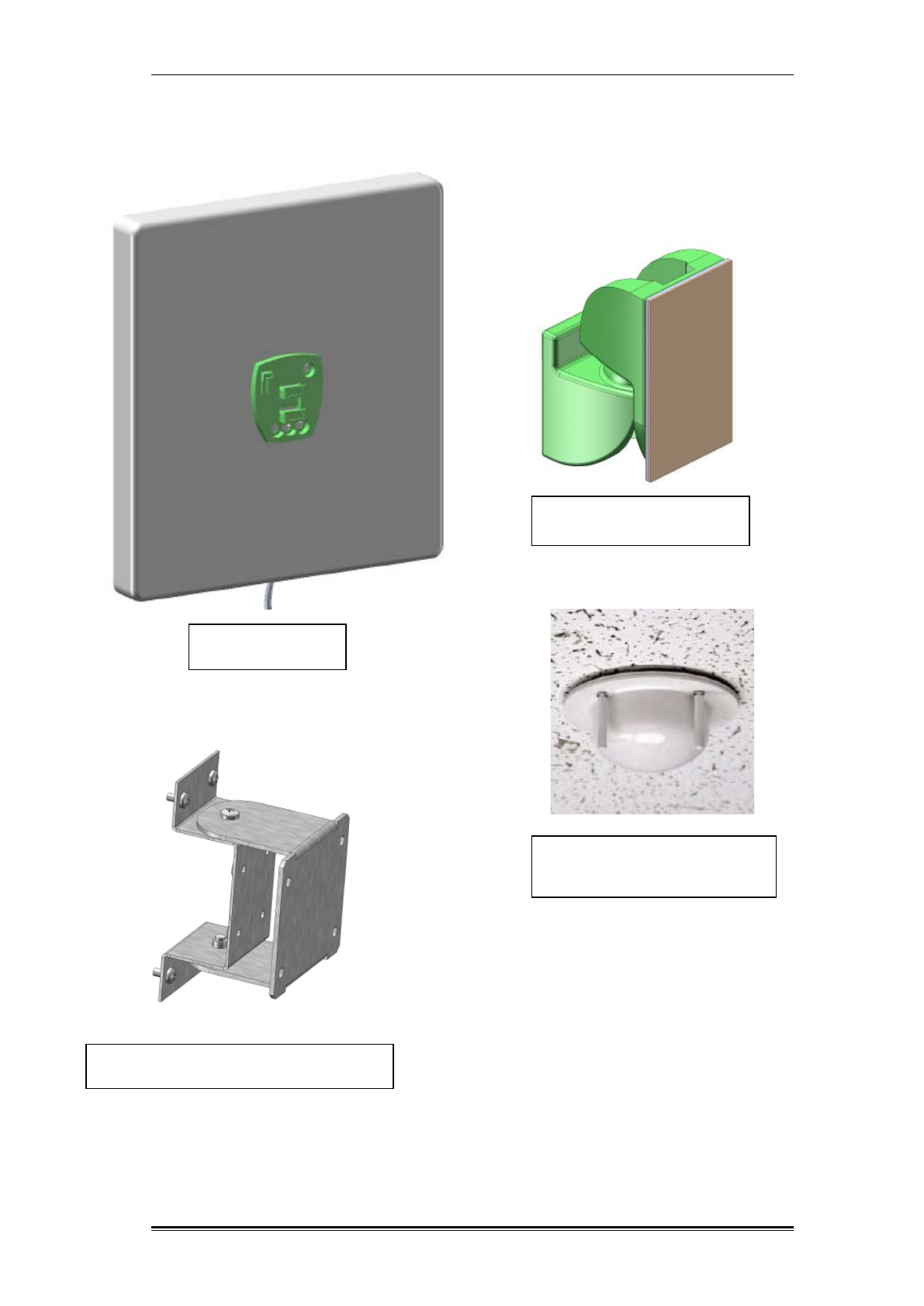
1.3 WHAT’S IN THE BOX - REPEATER ACCESSORIES
Donor antenna front window
mounting bracket
Donor antenna
ANT-2527-10-19-AA
Donor antenna rear wall mounting bracket
Service In-Building multipurpose
antenna MPA-2300
(Not supplied by Cellvine)
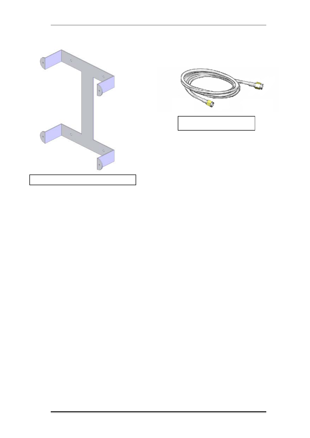
System Description What’s in the box - Repeater Accessories
TDD Mini Repeater: BDA-TDD-25-16-19-AA, Rev 2.2 Oct. 2008 © 2008 all rights reserved. Page 4
Bracket for TDD repeater: BRK-TDD-19-AA
Flexible coaxial cables (10m)
0- CON0343

System Description Indoor Repeater
TDD Mini Repeater: BDA-TDD-25-16-19-AA, Rev 2.2 Oct. 2008 © 2008 all rights reserved. Page 5
1.4 INDOOR REPEATER
Cellvine's indoor repeaters are intended for installation in indoor locations only.
Do not install in places where the repeater might be exposed to direct sunlight
and rain/snow conditions, as this could result in the damage to the unit and other
hazards. For normal operation, the environmental conditions should be as
follows: Ambient temperature range: 23 0F to 122 0F, Maximum humidity: 90%.
1.5 PREPARATION FOR INSTALLATION
Determine the following before beginning the repeater installation:
Base station location and receiving power (TX power in dBm)
Location where the Base/Mobile antenna is to be installed
Location where the repeater is to be installed
Length and type of coaxial cable needed to connect from the outdoor
antenna to the repeater unit
Length and type of coaxial cable needed to connect from the repeater
unit to the indoor antenna
Estimation of the isolation between the donor and the coverage
antenna/s
System Description Repeater Unit RF Specifications
TDD Mini Repeater: BDA-TDD-25-16-19-AA, Rev 2.2 Oct. 2008 © 2008 all rights reserved. Page 6
1.6 REPEATER UNIT RF SPECIFICATIONS
Table 1: Repeater technical specifications
Parameter
Specifications
Frequency range 2500-2690 Mhz
Output composite
power UL : 16 dBm , DL : 16 dBm
System max gain
80 dB
Noise figure
Less than 7 dB
Pass band ripple
4 dB p-p in 10 Mhz bands
IF filter rejection
40 dB @ 1 Mhz
Band filter options Center frequency –200 Khz steps BW OF : 10
Mhz,
Gain tuning range 23 dB in 1 dB steps
Switching time
Less than 2 µsec
Absolute delay
Less than 4 µsec
Protection
Overpower Programmable shut down
VSWR
2:1 MAX
Operating conditions Indoor (-23 to +122
0
F)
Indicators/Controls
Led : DC Power ,AGC, alarm Gain tuning knobs
Available software
tuning Full software control by local PC terminal
Sync method
IP -Wireless 3G broadband wireless modem TTL
signal
Dimension 13.77” X 9.00” X 3.93”
Power requirements
7.5 VDC, 1.5A Max. from included power supplier
System Description Repeater Dimensions
TDD Mini Repeater: BDA-TDD-25-16-19-AA, Rev 2.2 Oct. 2008 © 2008 all rights reserved. Page 7
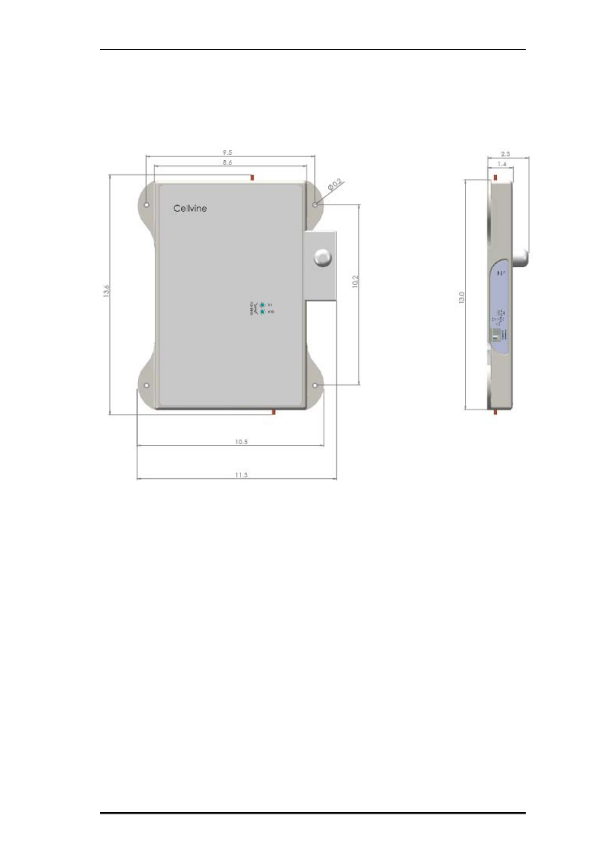
1.7 REPEATER DIMENSIONS
(In inches)
Figure 1: Repeater dimension
System Description Bracket Dimensions
TDD Mini Repeater: BDA-TDD-25-16-19-AA, Rev 2.2 Oct. 2008 © 2008 all rights reserved. Page 8
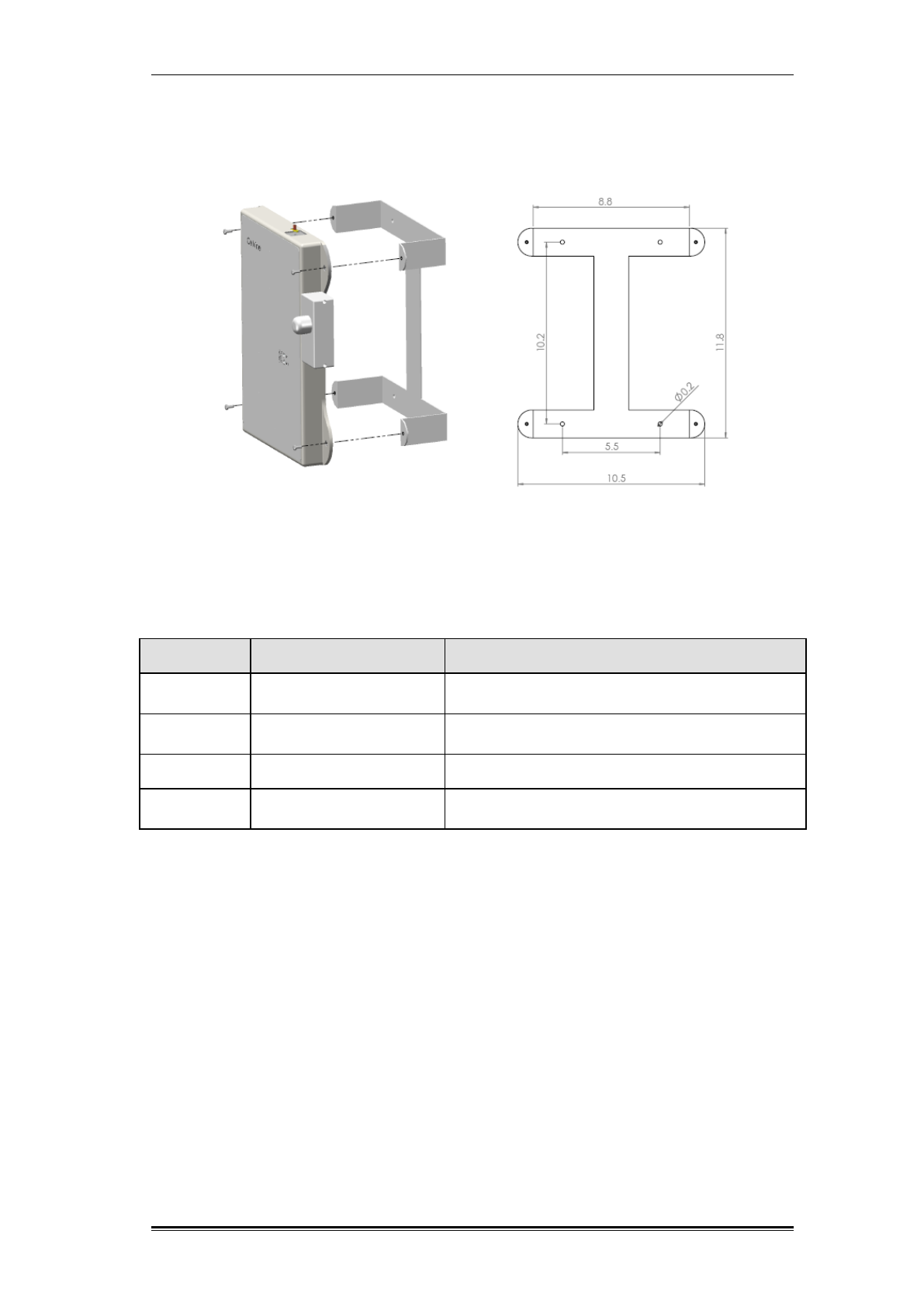
1.8 BRACKET DIMENSIONS
Figure 2: Bracket dimensions
1.9 REPEATER INTERFACES
Name Type Function
MOBILE
SMA Female
connector
Connect to service antenna
BASE
SMA Female
connector
Connect to donor antenna
POWER
Cross connector
Connect to power supply
Software
Control
Mini USB-USB
Connect to maintenance and control software
GUI
Table 2: Repeater interfaces
1.10 ANTENNAS
The system incorporates two antenna types:
Donor panel antenna: Installed facing out the area to be covered
Coverage antenna(s): One or more antennas installed at the area to be
covered.
The donor antenna receives cellular signals (assuming sufficient coverage exists
outside the building or near a window). The BDA amplifies the signals
transmitted by the coverage antennas in the coverage areas. The mobile
handset signals are received by the coverage antennas, amplified by the BDA,
and transmitted through the donor antenna back to the cellular base station site.
This enables cellular signals to be re-transmitted in some locations, in order to
extend cellular coverage.
System Description Antennas
TDD Mini Repeater: BDA-TDD-25-16-19-AA, Rev 2.2 Oct. 2008 © 2008 all rights reserved. Page 9
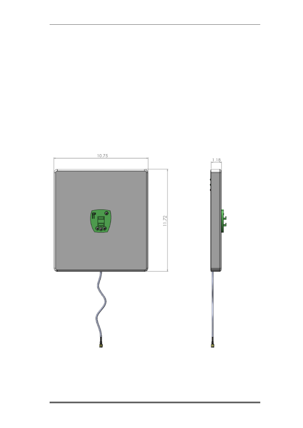
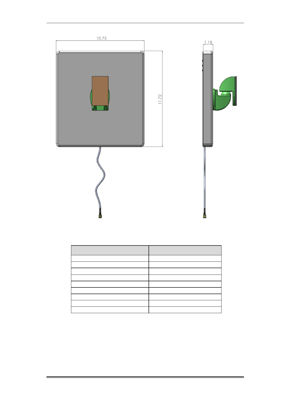
1.10.1 Donor Panel Antenna
Cellvine provides a unique, slim and well-designed donor antenna in the
repeater kit, instead of a regular Yagi antenna. This antenna is designed to
provide attractive appearance and smaller dimension when installed in private
homes or public places. The solution is based on a panel antenna with a narrow
beam pattern of 24º.
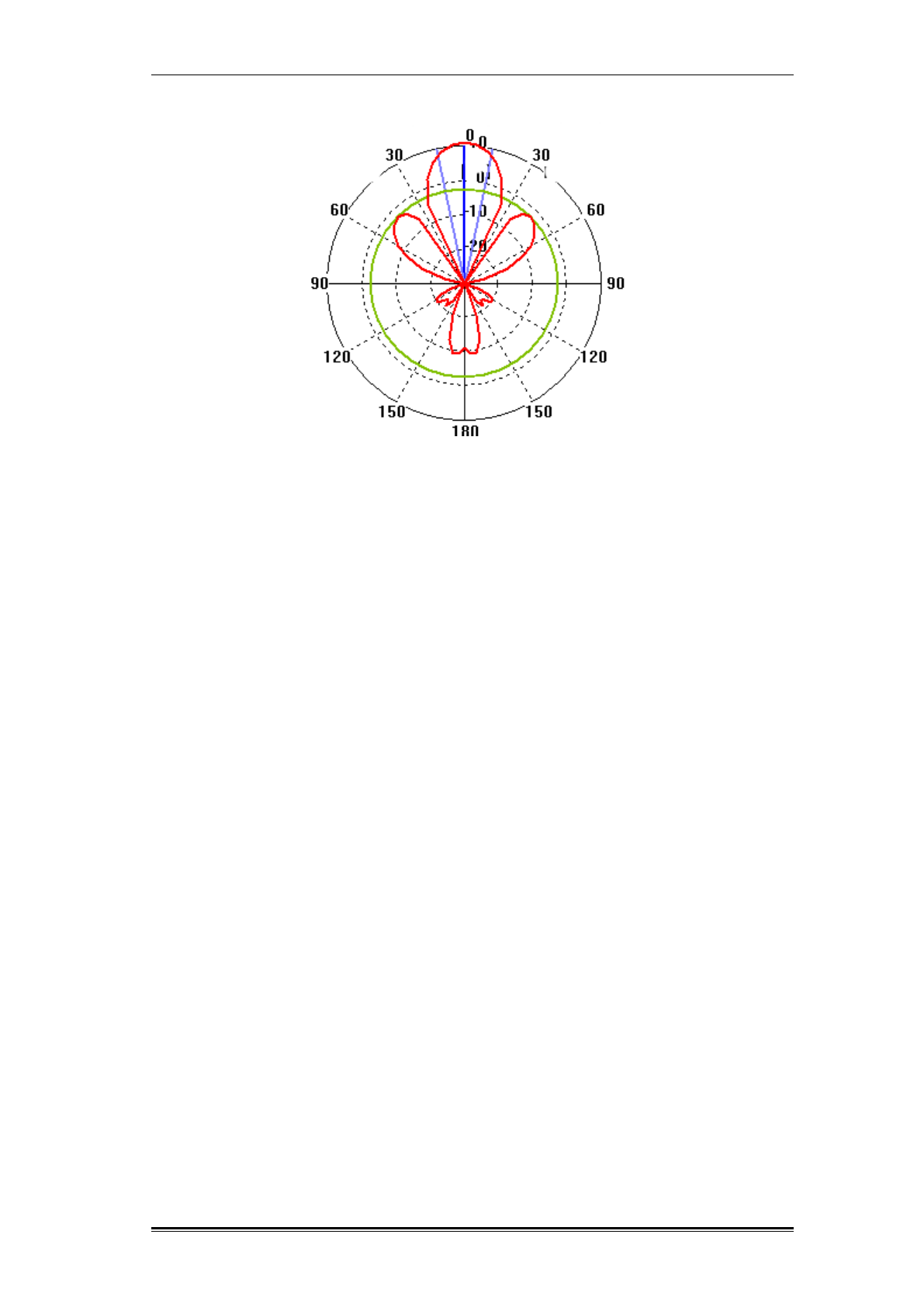
The advantages of this antenna are being aesthetically more appealing,
lightweight, relatively small dimensions, and simple installation. Although this is a
panel antenna, it performs much better than other panel antennas with similar
dimensions, especially in the pattern beam width (see Figure 5). The antenna
gain is 9 dBi.
The antenna is designed to be mounted on a glass window, using a window
bracket that is attached to the window with two-sided adhesive tape. For the
adhesive tape specifications, please see Adhesive tape specifications, page 13.
Figure 3: Donor panel antenna dimension in inches
System Description Antennas
TDD Mini Repeater: BDA-TDD-25-16-19-AA, Rev 2.2 Oct. 2008 © 2008 all rights reserved. Page 10
Figure 4: Donor panel antenna dimension in inches with front window bracket
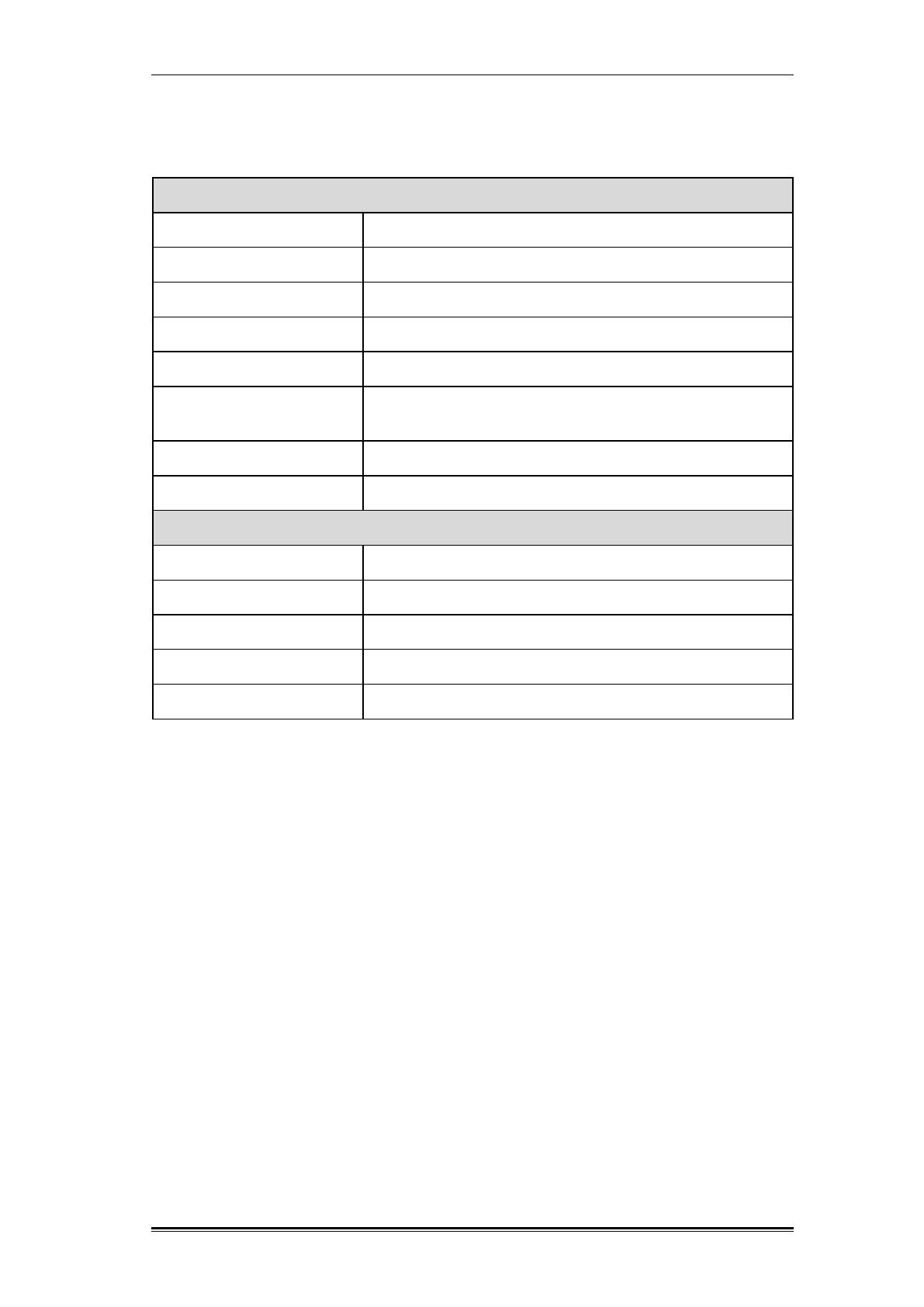
Frequency range 2500-2700 MHz
Directivity
9 dBi
VSWR
1.8:1 (typical)
3 dB Beam width
24
°
X 24
°
Polarization
Lineal
Input impedance
50 (ohm)
F/B ratio
20 dB (typical)
Input power
10W
Size
307X277X30mm
Weight
2 Kg
Table 3: Panel donor antenna unit specifications
System Description Antennas
TDD Mini Repeater: BDA-TDD-25-16-19-AA, Rev 2.2 Oct. 2008 © 2008 all rights reserved. Page 11
Figure 5: Donor antenna horizontal radiation pattern
System Description Donor Signal Strength Measurement Tool
TDD Mini Repeater: BDA-TDD-25-16-19-AA, Rev 2.2 Oct. 2008 © 2008 all rights reserved. Page 12
1.11 DONOR SIGNAL STRENGTH MEASUREMENT TOOL
The donor panel antenna includes a signal level meter indicator (Figure 6) for
measuring the RSSI signal level from the donor BTS in the neighboring area.
The measurement tool receives a signal from the repeater controller through the
coax cable connected to the donor antenna. It measures the signal output level
of the repeater output according to the signal received at the donor antenna from
the BTS. This will help installing the donor antenna in the optimal direction and
at the optimal angle, in order to achieve the highest RSSI level signal from the
BTS.
For operation instructions, please refer to Tuning Donor Antenna via Signal
Level Indicator, page 24.
Figure 6 : Donor signal level measurement tool
System Description Donor Signal Strength Measurement Tool
TDD Mini Repeater: BDA-TDD-25-16-19-AA, Rev 2.2 Oct. 2008 © 2008 all rights reserved. Page 13
1.11.1 Indoor Omni Coverage Antenna Specifications
Electrical Specifications
Frequency Range 2300-2700MHz
VSWR
≤2.0
Input Impedance
50Ω
Gain
3dBi
Polarization
Vertical
Maximum Input
Power 50W
Connector Type SMA -Male
Lightning Protection
DC ground
Mechanical Specifications
Height
105mm
Weight
62g
Cable Length 3m
Antenna Color
Black
Working Temperature
-40~140 0F
Table 4 : Indoor Omni coverage antenna specification
1.11.2 Adhesive tape specifications and installation recommendation for the antenna
mounting bracket
After application, the bond strength will increase as the adhesive flows onto the
surface. At room temperature approximately 50% of ultimate bond strength will
be achieved after 20 minutes, 90% after 24 hours and 100% after 72 hours. This
flow is faster at higher temperatures and slower at lower temperatures. Ultimate
bond strength can be achieved more quickly (and in some cases bond strength
can be increased) by exposure of the bond to elevated temperatures (e.g. 150°F
[66°C] for 1 hour). This can provide better adhesive without on to the substrates.
Abrasion of the surfaces or the use of primers/ adhesion promoters can also
have the effect of increasing bond strength and achieving ultimate bond strength
more quickly.

Installation Unpacking and Inspection
TDD Mini Repeater: BDA-TDD-25-16-19-AA. Rev 2.2 Oct. 2008, © 2008 all rights reserved. Page 14
2 INSTALLATION
This section provides information about the installation and setup of the Cellvine
repeaters. The information consists of procedures for unpacking, inspection and
preparation for the installation, as well as the actual installation and setup. It is
important to install the repeater correctly at its working location.
It is recommended that installation be performed by a certified radio technician.
The repeater installation consists of four basic steps:
5. Antenna installation
6. repeater installation
7. Cable installation
8. Repeater parameters setup and tuning with the control application.
2.1 UNPACKING AND INSPECTION
1. Examine the shipping package for damage before unpacking the unit. If the
shipping package is damaged, try to unpack the equipment in the presence of
the carrier’s agent. If visual inspection reveals physical damage to the
equipment, you should send it back for replacement.
2. Verify that the equipment includes all components, as listed in the packing slip. If
components are missing, contact Cellvine Ltd.
2.2 ANTENNA INSTALLATION
Coverage (mobile) antenna – facing to the "no coverage" area. The most
commonly used antennas for indoor applications are Omni or panel antennas.
When multiple indoor areas should be covered, more than one antenna can be
used. Indoor antennas are usually placed near the ceiling with decorative
covers. Decisions as to where to locate the antenna take into account isolation
issues, and the need to overcome interfering signals. For outdoor coverage,
panel antennas are commonly used. The location of the antenna is determined
by coverage and isolation matter.
Base (donor) antenna – installed behind a window glass, facing the donor BTS.
The choice of donor cell site should take into consideration capacity, range and
signal level in the outdoor antenna location. The location should be chosen so,
that donor cell site reception will be at a higher level than all other adjacent cell
sites. For this purpose, the outdoor antenna should have high directivity and
high Gain. If possible, this antenna should directly face the nearest cellular site
with a line-of-sight view. For further installation instructions, please refer to
paragraph Donor Antenna Installation, page 15.
Isolation issue – to assure proper repeater operation, the isolation between the
indoor (Mobile) and outdoor (Base) antennas should be at least 15 dB higher
than the repeater's maximal gain.
This isolation parameter can be measured simply by transmitting a continuous,
CW unmodulated pilot signal of 0 dBm at the repeater Base port (donor
antenna), and measuring the received signal at the repeater Mobile port (service
antenna port).

Installation Pre-Installation Inspection
TDD Mini Repeater: BDA-TDD-25-16-19-AA, Rev 2.2 Oct. 2008 © 2008 all rights reserved. Page 15
Note: the isolation parameter should be measured between the coax cables
that are connected to the Base and Mobile ports, without the repeater.
For example, if the measured isolation parameter between the Base and Mobile
ports is 90 dB, the maximal repeater gain should not exceed 75 dB.
2.3 PRE-INSTALLATION INSPECTION
Before beginning the repeater installation, determine the following:
Base station location and receiving power (TX power in dBm)
Location where the Base/Mobile antenna is to be installed
Location where the repeater is to be installed
Length of coaxial cable needed to connect from the Donor antenna to
the repeater unit
Length of coaxial cable needed to connect from the repeater unit to the
indoor antenna/s.
Isolation estimation between the donor and the coverage antenna/s.
2.4 DONOR ANTENNA INSTALLATION
The panel donor antenna can be installed either attached to a window glass,
using the front window mounting bracket, or on a wall or flat surface using the
rear wall mounting bracket.
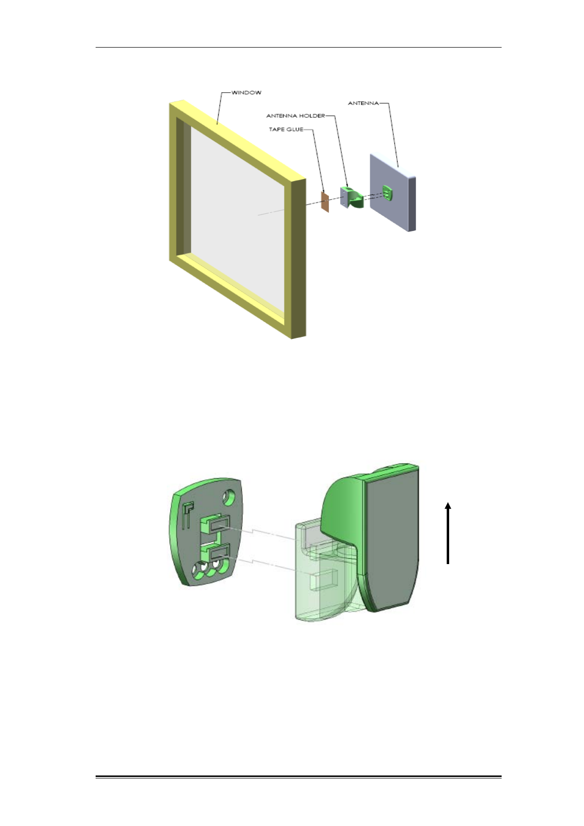
2.5 ANTENNA WINDOW INSTALLATION
To install the antenna attached to a window glass, perform the following steps:
1. Locate all the antenna’s front bracket parts, as shown in Figure 7.
2. Attach the antenna holder to the antenna adaptor installed on the front of the
antenna, as shown in Figure 8.
3. Glue the antenna holder to the most suitable spot on the window. Before gluing,
clean and remove fat and dust from the gluing area. Note that the adapter
should be glued onto the window vertically. The adapter must be glued pointing
up, see Figure 8 and Figure 9.
4. Press the antenna and front bracket gently onto the window, and wait a few
seconds to ensure that it is properly attached, as shown in Figure 9.
RF exposure warning! In order to comply with FCC RF exposure
regulations, you must ensure that the donor antenna is installed at a
minimum distance of 0.2 m (7.8 inches) from persons who may be present in
the area.
Installation Antenna Window Installation
TDD Mini Repeater: BDA-TDD-25-16-19-AA, Rev 2.2 Oct. 2008 © 2008 all rights reserved. Page 16
Figure 7: Installing donor antenna on window
Figure 8: Connecting antenna holder to antenna adaptor
Installation Antenna Window Installation
TDD Mini Repeater: BDA-TDD-25-16-19-AA, Rev 2.2 Oct. 2008 © 2008 all rights reserved. Page 17
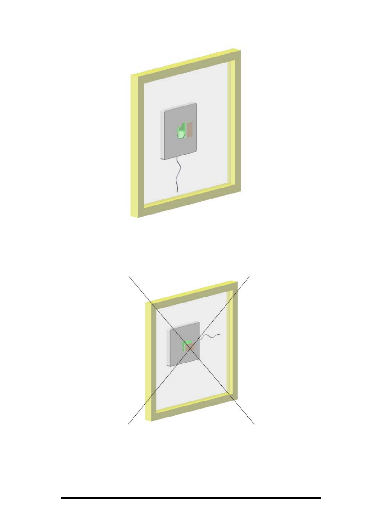
Figure 9: Front view of donor installation on window glass – Correct installation
Figure 10: Wrong installation
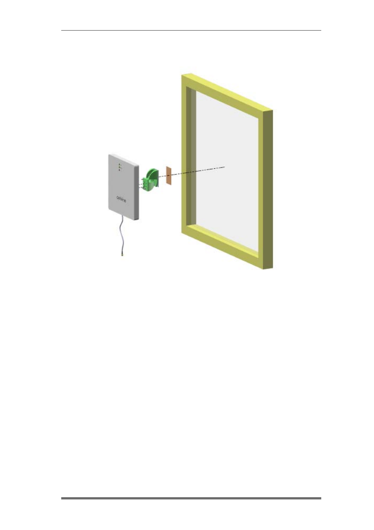
Installation Antenna Window Installation
TDD Mini Repeater: BDA-TDD-25-16-19-AA, Rev 2.2 Oct. 2008 © 2008 all rights reserved. Page 18
Figure 11: Rear view of donor antenna window installation
Installation Donor Antenna Wall Installation
TDD Mini Repeater: BDA-TDD-25-16-19-AA, Rev 2.2 Oct. 2008 © 2008 all rights reserved. Page 19
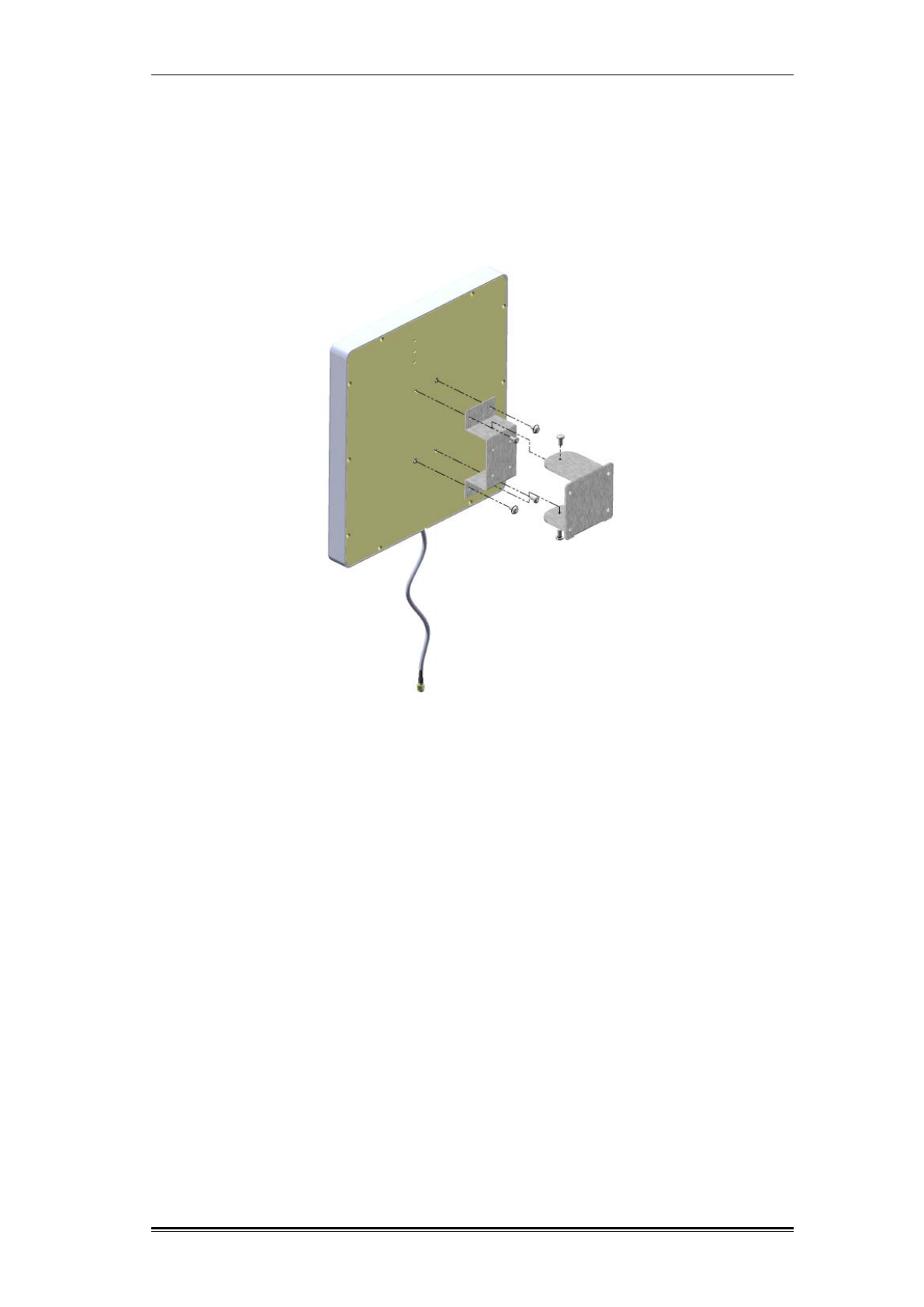
2.6 DONOR ANTENNA WALL INSTALLATION
To install the donor antenna attached to a wall or flat surface, connect the donor
antenna to the wall bracket using the supplied bracket kit, as shown in Figure
10.
Figure 12: Donor Antenna Wall Bracket Assembly
For aesthetic reasons, a sticker is placed on the back panel, covering the screw
holes. In order to locate the screw holes on the back of the panel and insert the
screws:
1. Place the paper stencil, provided in the antenna kit, over the back of the
antenna, and use a pencil or a pen to mark the position of the four holes on the
back panel of the antenna.
2. Use a Stanley knife to make holes in the sticker on the back of the antenna at
the marked points.
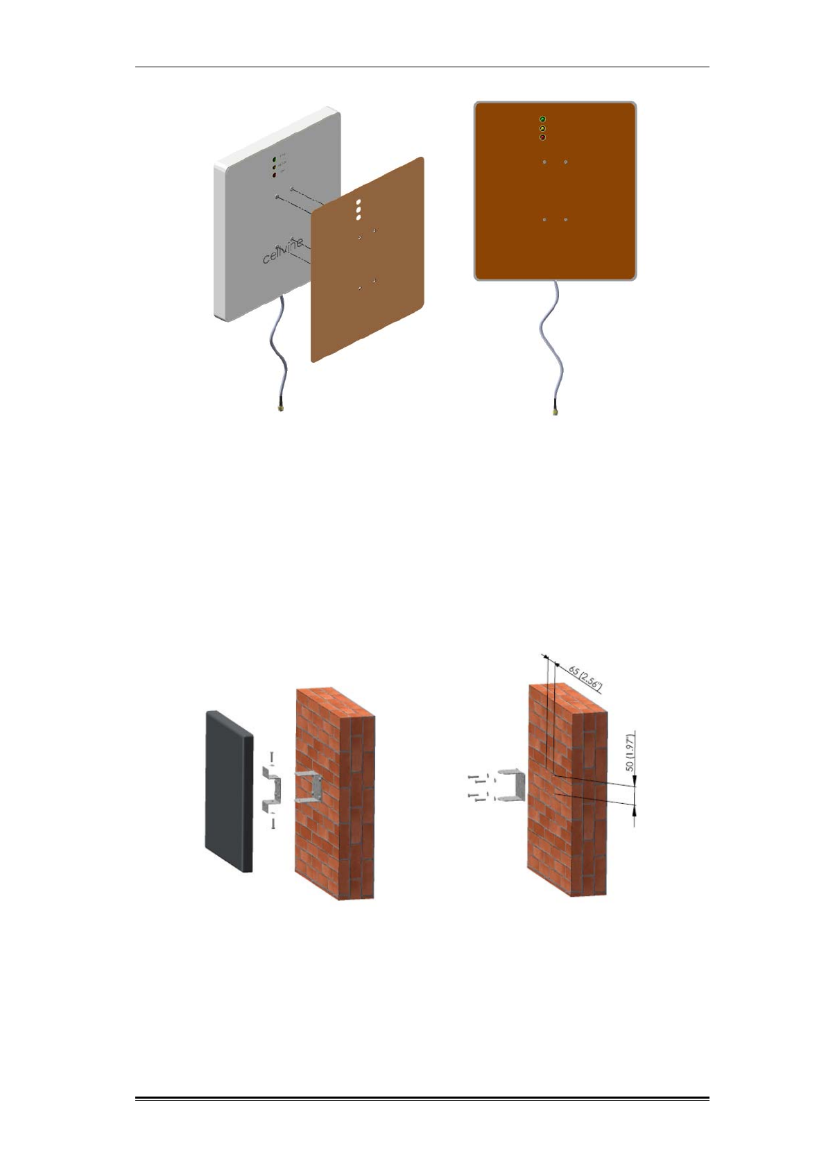
Installation Donor Antenna Wall Installation
TDD Mini Repeater: BDA-TDD-25-16-19-AA, Rev 2.2 Oct. 2008 © 2008 all rights reserved. Page 20
Figure 12: Making holes in back panel sticker for rear wall bracket installation
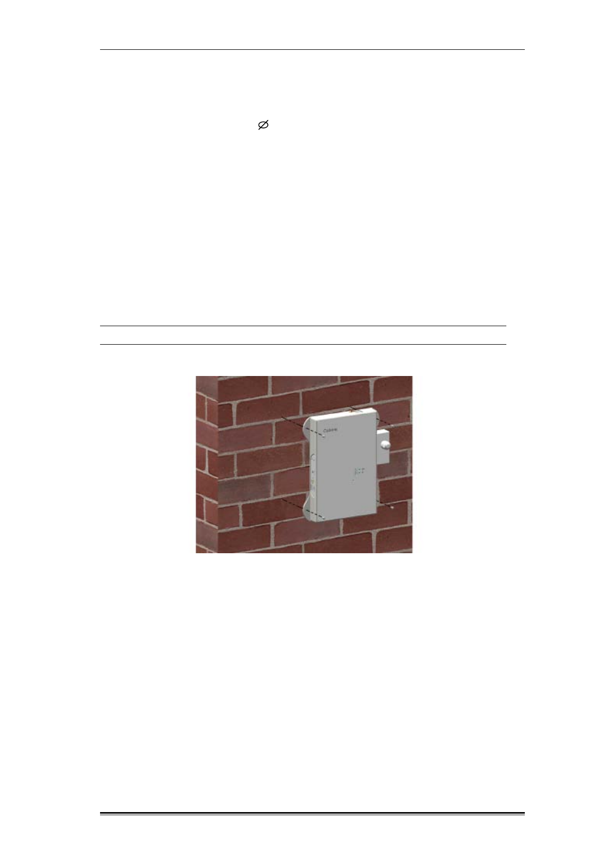
3. Use the supplied four screws to attach the appropriate bracket part to the back
of the antenna, see Figure 12.
4. Attach the appropriate bracket part to the wall (no screws are supplied for this
step. The required screw and masonry anchor type varies according to the wall
type).
5. Connect the two bracket parts using the supplied screws.
Figure 13 : Donor antenna wall installation
Installation Repeater Unit Mechanical Installation
TDD Mini Repeater: BDA-TDD-25-16-19-AA, Rev 2.2 Oct. 2008 © 2008 all rights reserved. Page 21
2.7 REPEATER UNIT MECHANICAL INSTALLATION
1. In order to install the repeater on a wall or a similar surface, use the mounting
holes on the side of the repeater as shown in Figure 14: Repeater wall
installation. Use four fixing 4 screws, socket pan screws, plain washer, and a
spring washer (not supplied).
2. Make sure that the antenna cable connectors and the repeater connectors are
clean and dry.
3. Connect the donor antenna cable to the "base" RF connector.
4. The connection should be snug and tight.
5. Connect the "mobile" (coverage) antenna cable to the mobile RF connector. The
connection should be snug and tight.
6. Ensure that the antenna cables have are not crimped, kinked, or otherwise
damaged in the process.
7. Connect AC adaptor to the AC socket.
Note: Always connect RF connectors to repeater before applying AC supply!
Figure 14: Repeater wall installation
Installation Cable and Mounting Installation Precautions
TDD Mini Repeater: BDA-TDD-25-16-19-AA, Rev 2.2 Oct. 2008 © 2008 all rights reserved. Page 22
2.8 CABLE AND MOUNTING INSTALLATION PRECAUTIONS
Danger of electrical shock. This equipment is usually installed outdoors.
Wet conditions increase the potential for receiving an electric shock when
installing or using electrically powered equipment. To prevent electrical
shock when installing or modifying the system power wiring, disconnect
the wiring at the power source before working with insulated wires or
terminals.
Make sure that the antenna connectors and the antenna cable connectors
are clean and dry.
The RF cables must not be kinked, cut or damaged in any way.
Connect the RF cables to the antennas. Be carfull not to strip the
connectors. The connection should be snug and tight.
Seal the connectors with either a waterproof sealant, or the appropriate
weather tight boot.
Make sure that the AC power is suitable for the repeater in use.
Make sure that all indoor repeaters are installed without direct sun
radiation and rain protection.
Whenever loose cables are left on the ground, a clear sign must be added
to warn passing pedestrians of the danger of entanglement.
Always connect RF connectors to repeater before applying AC supply!
Maximum input power at Base Port is - 40 dBm in AGC ON mode.
Installation Synchronization PCMCIA Modem Installation
TDD Mini Repeater: BDA-TDD-25-16-19-AA, Rev 2.2 Oct. 2008 © 2008 all rights reserved. Page 23
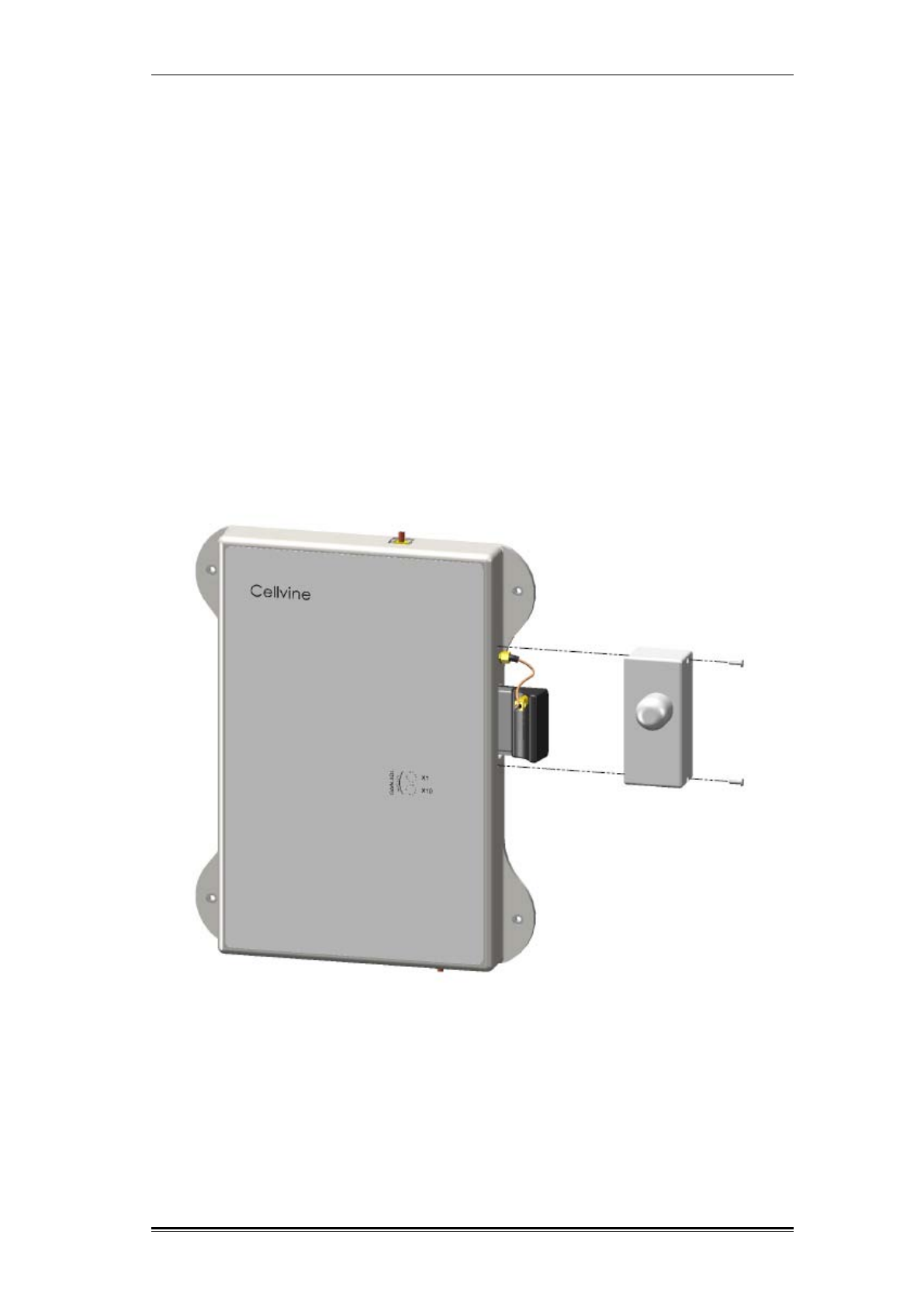
2.9 SYNCHRONIZATION PCMCIA MODEM INSTALLATION
The Synchronization PCMCIA modem and the modem cover are assembled and
ready for use in the repeater package.
If a modem replacement is needed, please perform the following steps:
1. Remove the modem cover by loosening the screws on the cover sides.
2. Disconnect the modem receiving signal cable from the modem socket.
3. Pull the modem back from the modem slot.
4. Replace the modem.
5. Insert the modem into the slot and slide the modem forward until it stops.
6. To make sure the modem is connected to the connector socket at the modem
slot, tighten the modem gently towards the repeater.
7. Connect the modem receiving signal cable to the modem socket.
8. Replace the modem cover.
Figure 15: Synchronization modem installation
Installation Tuning Donor Antenna via Signal Level Indicator
TDD Mini Repeater: BDA-TDD-25-16-19-AA, Rev 2.2 Oct. 2008 © 2008 all rights reserved. Page 24
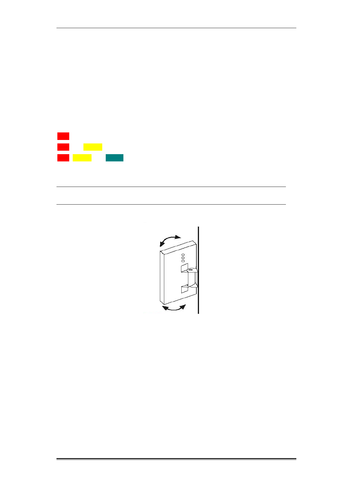
2.10 TUNING DONOR ANTENNA VIA SIGNAL LEVEL INDICATOR
Locate a potential site for installing the donor antenna with an accessible and
comfortable working space. If possible, select one of the surrounding BTS's
highest donor level signals. Deploy and connect a coax cable between the donor
antenna and the repeater location (into the Base connector) and make sure the
repeater is powered ON and the coverage antenna (Mobile) is connected.
To achieve the best signal reception quality at the donor antenna, rotate the
antenna gently sideways, as shown in Figure 16.
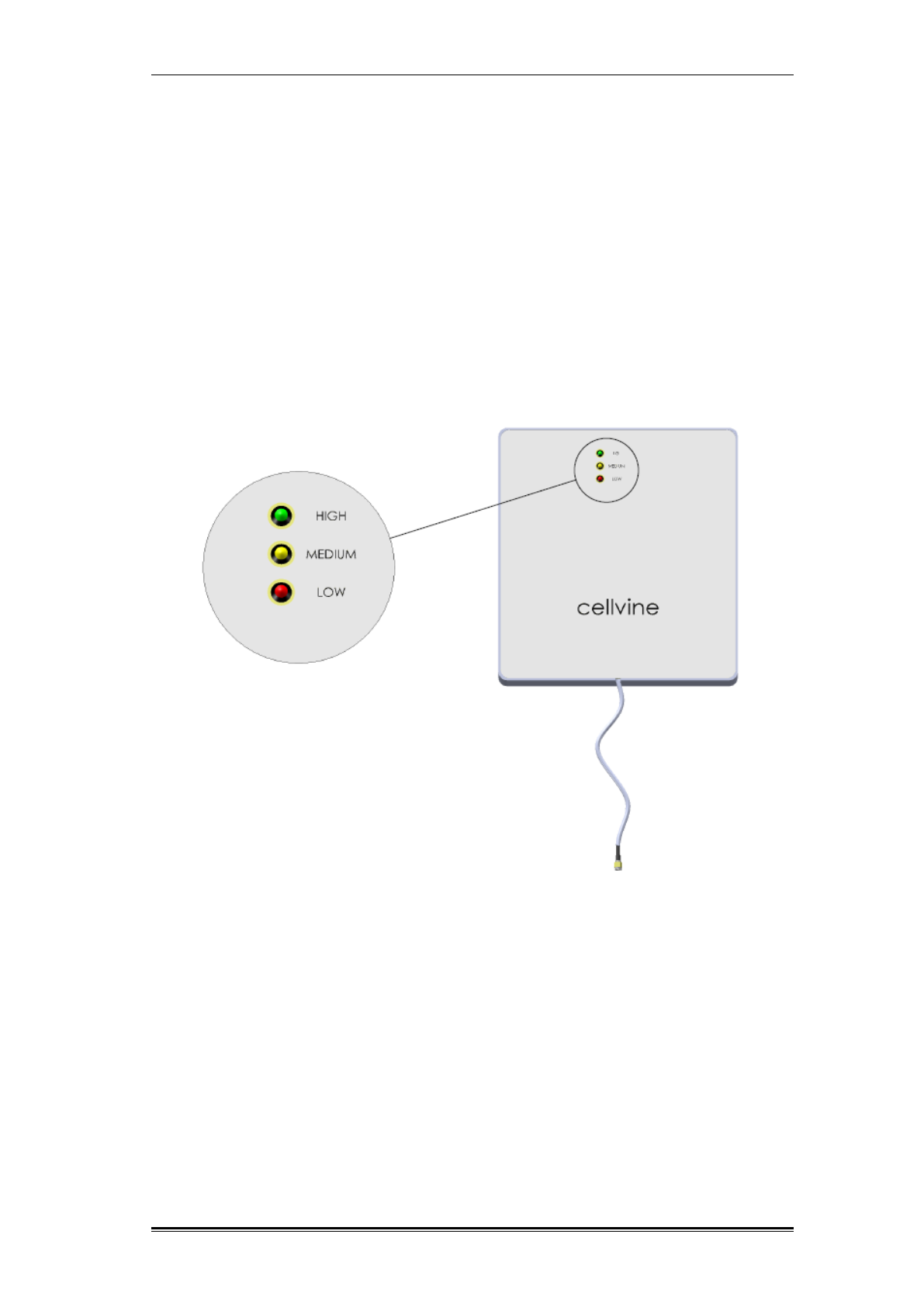
While rotating the antenna, observe the signal level indicator LEDs on the back
panel of the antenna, as follows:
Red LED – lowest level
Red and Yellow LED – medium level
Red, Yellow and Green LED – highest level
Note: make sure the repeater is turned on and connected to the donor and
service antennas while rotating the antenna.
Figure 16: Antenna signal level indicator tuning
Repeater Communication, Monitoring and Control Local Cable Control Mode
TDD Mini Repeater: BDA-TDD-25-16-19-AA. Rev 2.2 Oct. 2008, © 2008 all rights reserved. Page 25
3 REPEATER COMMUNICATION, MONITORING AND CONTROL
Cellvine TDD Mini repeaters are equipped with a controller microprocessor and
can be fully controlled and monitored through a local connection, or remotely
using an optional modem, and a software utility.
3.1 LOCAL CABLE CONTROL MODE
To operate and control the repeater with a PC or laptop computer in local mode,
connect the USB control cable between the computer and the Mini USB port
located on the side panel of the repeater.
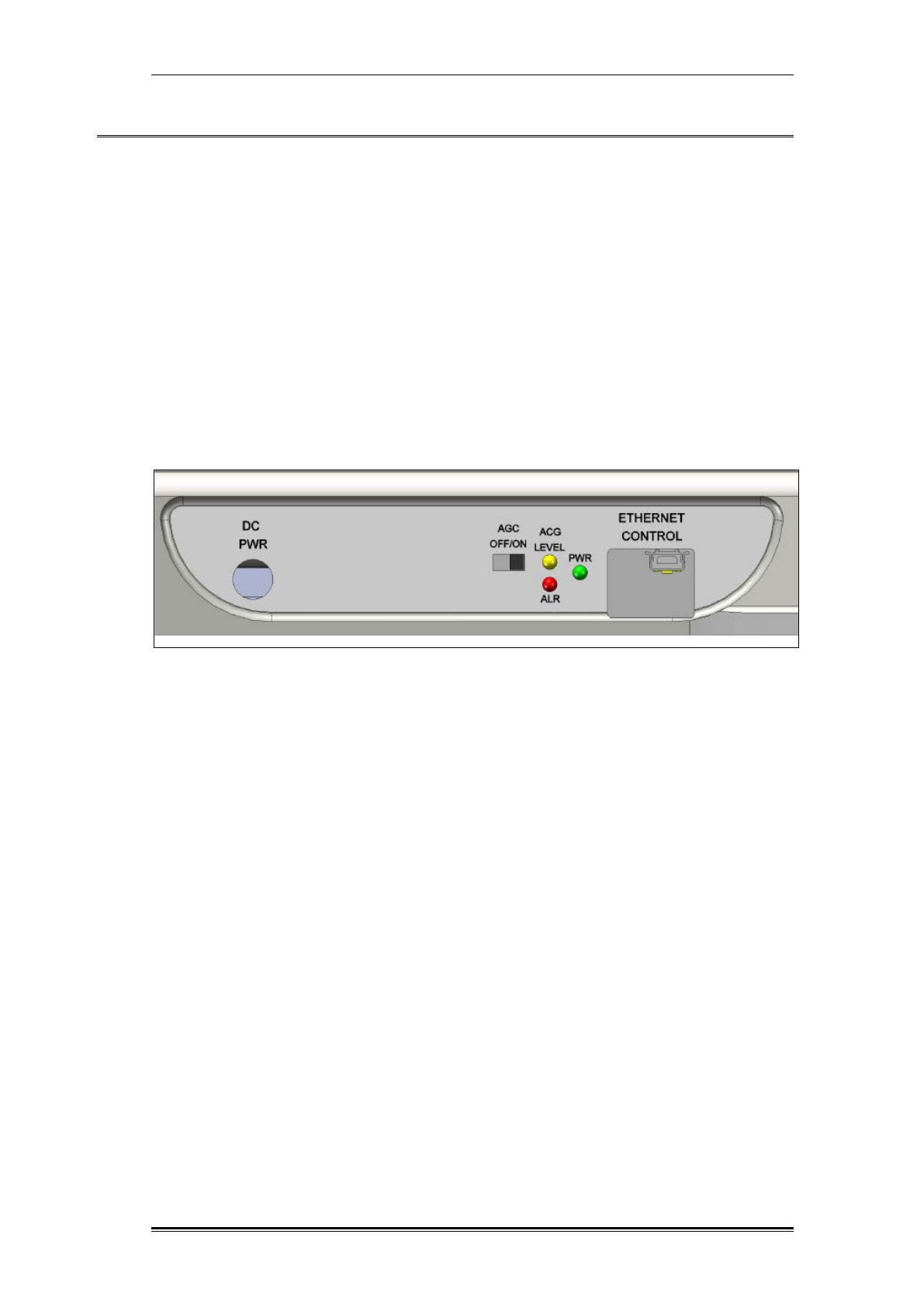
3.2 REPEATER MANUAL ADJUSTMENTS
The AGC ON/OFF switch and the Status LED are located on the side panel of
the repeater. The Manuel GAIN ADJ variable rotation knobs (for AGC OFF
mode) are located on the front panel.
Figure 17: Repeater control panel

Repeater Communication, Monitoring and Control Repeater AGC ON - Operation Mode
TDD Mini Repeater: BDA-TDD-25-16-19-AA, Rev 2.2 Oct. 2008 © 2008 all rights reserved. Page 26
3.3 REPEATER AGC ON - OPERATION MODE
By default, when setting the AGC switch to ON, the repeater should work in fully
automatic mode. In this mode, the Gain of the repeater will be set automatically
to ensure that the output power is equal to the maximal linear power of the
repeater.
In instances where the signals exceed the linear level, an automatic attenuator
will reduce the Gain.
If the signal in the input of the repeater increases, the repeater will reduce the
Gain in order to achieve the AGC parameter value that was set. If the input
signals from the BTS decrease after a while, the Gain of the repeater will
increase again, by 1 dB.
Note: the AGC ON mode can be set either manually from the side panel, or
by using the control Software
3.4 AGC OFF-OPERATION MODE
In AGC OFF mode, the AGC mechanism is no longer in control of the increase
or decrease of the repeater Gain. The Gain level in AGC OFF operation mode is
fixed, and will not be changed automatically by the repeater. In light of this, it is
important to measure and control the input level of the signal coming from the
BTS.
Example: in AGC OFF mode, the Gain is fixed at 80 dB. The maximum output
level allowed from the unit is 16 dBm, and the maximum input signal level from
the BTS is therefore 16-80 = - 64 dBm. This means that if the input signal from
the BTS is higher, e.g., -55 dBm, and the fixed Gain is 80 dB, the output level
will be -55+80= +25 dBm.
This repeater model is designed for a maximum of + 16 dBm output power, and
+25 dBm output power levels will damage the unit.
You can configure the output power in AGC OFF mode and set the repeater
Gain manually, by using the two rotation knobs on the front panel. In AGC OFF
mode, the knobs on the front panel are used as attenuators in order to reduce
the maximum Gain of the repeater (80 dB), by up to 23 dB (in the range of 80-57
dB).
Repeater Communication, Monitoring and Control AGC OFF-Operation Mode
TDD Mini Repeater: BDA-TDD-25-16-19-AA, Rev 2.2 Oct. 2008 © 2008 all rights reserved. Page 27
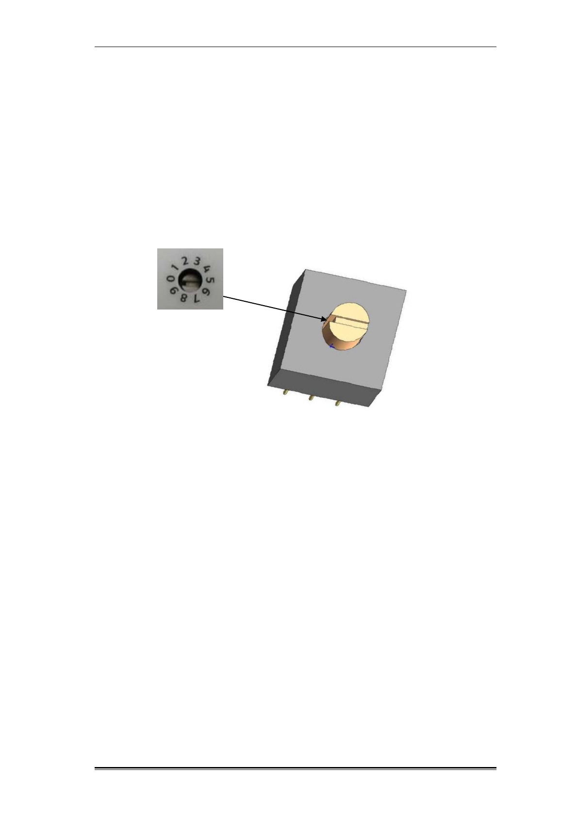
3.4.1 Using the Variable Rotation Knobs in AGC OFF Mode
To set the Gain parameters by using the variable knobs on the front panel,
please follow these steps:
1. Set AGC to OFF mode by changing the switch on the repeater side panel to the
OFF position.
2. Use a small flathead screwdriver to rotate the knob to the desired position.
3. Rotate the knob so that the blank edge is pointing to the desired digit, as shown
in Figure 18.
Figure 18: Rotate knob setup position
Repeater Communication, Monitoring and Control AGC OFF-Operation Mode
TDD Mini Repeater: BDA-TDD-25-16-19-AA, Rev 2.2 Oct. 2008 © 2008 all rights reserved. Page 28
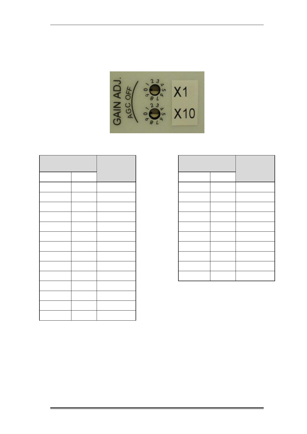
3.4.2 Setting the Gain in Manual Adjustment – AGC OFF Mode
To set the fixed Gain level in AGC OFF mode, use the variable rotation knob:
X 10; X 1
Figure 19: AGC OFF Gain attenuators variable rotation knob
Table 5: Setting the Gain in manual adjustment – AGC Off mode
Repeater
Gain- dB
Rotation Knobs
position
X10
X1
80
0
0
79 0 1
78
0
2
77
0
3
76
0
4
75
0
5
74
0
6
73 0 7
72
0
8
71
0
9
70
1
0
69
1
1
68
1
2
67
1
3
Repeater
Gain- dB
Rotation Knobs
position
X10
X1
66
1
4
65 1 5
64
1
6
63
1
7
62
1
8
61
1
9
60
2
0
59 2 1
58
2
2
57
2
3
Repeater Communication, Monitoring and Control LED Status
TDD Mini Repeater: BDA-TDD-25-16-19-AA, Rev 2.2 Oct. 2008 © 2008 all rights reserved. Page 29
3.5 LED STATUS
The system status is indicated by three LEDs.
Green – PWR: Indicates system power ON/OFF
RED-ALR: indicates various alarms
Yellow-AGC: refers to AGC operation level
OFF BLINK STEADY ON LED/STATUS
Forward power is 3 dB below
AGC level
Forward power at
AGC level
YELLOW
Shutdown after
overpower
protection process
RED
DC Power GREEN
Modem lost synchronization
with BTS
YELLOW &
RED
Table 6: LED Status indications
Software Installation System Requirements
TDD Mini Repeater: BDA-TDD-25-16-19-AA. Rev 2.2 Oct. 2008, © 2008 all rights reserved. Page 30
4 SOFTWARE INSTALLATION
The provided software allows you to access, modify and configure the repeater
parameters, receive alarms, and control the repeater locally.
The software provides various status indications and readouts.
The configurable parameters include Gain settings, power settings, alarm
settings and more.
4.1 SYSTEM REQUIREMENTS
Windows 2000/XP OS.
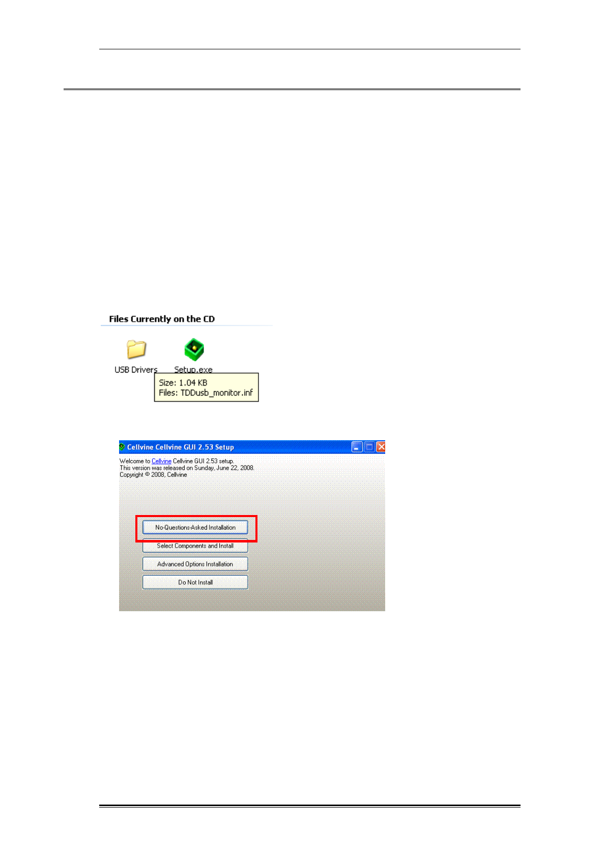
4.2 INSTALLING THE SOFTWARE
The software is provided on the CD supplied with the repeater.
1. Locate Setup.exe on the CD and start it.
2. Select “No-Questions-Asked Installation”.
3. Wait for the installation to end and click “Thanks!” at the final installation screen.
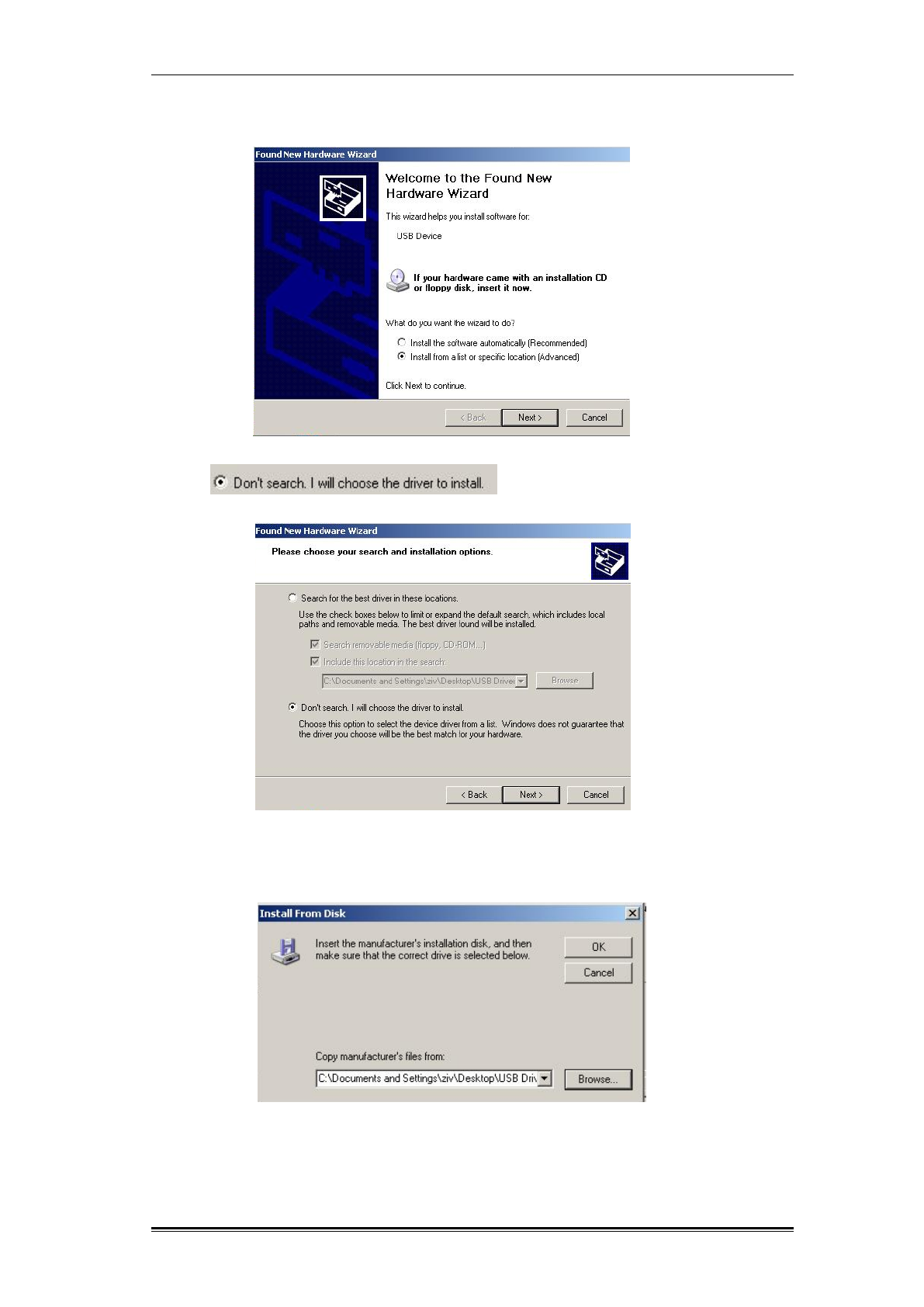
4.3 USB DRIVER INSTALLATION
(Once per workstation)
To control and monitor the repeater locally, USB drivers should be installed. This
procedure should be performed only once per PC.
1. Insert the USB Cable into the PC and the repeater.
2. Turn the repeater on - make sure the RF input and output are connected to the
antenna or to termination 50 Ohm.
Software Installation USB Driver Installation
TDD Mini Repeater: BDA-TDD-25-16-19-AA, Rev 2.2 Oct. 2008 © 2008 all rights reserved. Page 31
3. The New Hardware wizard opens. Click Next.
Select and click Next.
Drivers are located on the CD in the USB Drivers directory. Click OK.
Click Next.
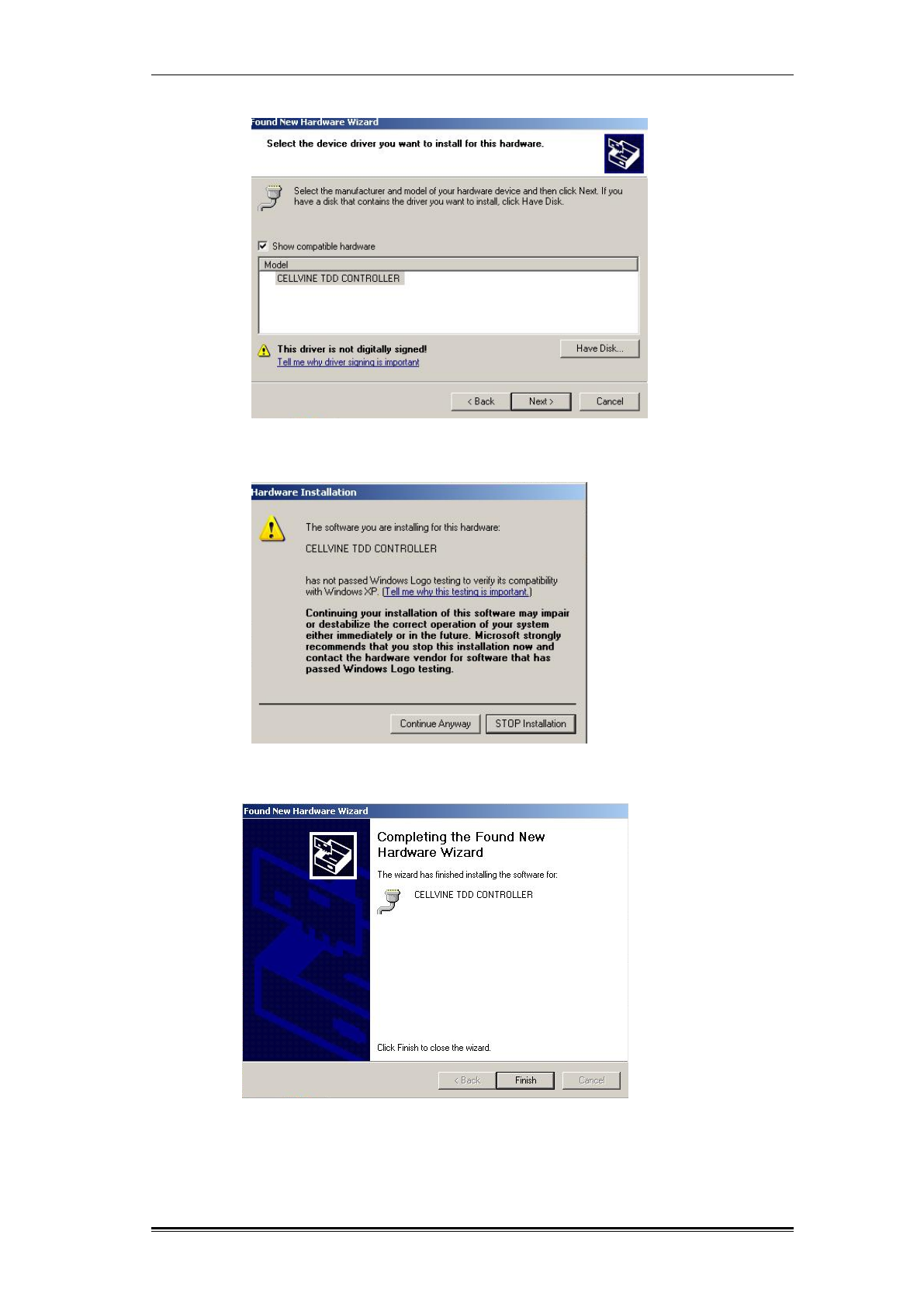
Software Installation USB Driver Installation
TDD Mini Repeater: BDA-TDD-25-16-19-AA, Rev 2.2 Oct. 2008 © 2008 all rights reserved. Page 32
Click Continue Anyway.
At the last installation screen click Finish.
Software Operation Technician setup screen
TDD Mini Repeater: BDA-TDD-25-16-19-AA. Rev 2.2 Oct. 2008, © 2008 all rights reserved. Page 33
5 SOFTWARE OPERATION
1. Connect the USB cable to the repeater and the PC/LAPTOP.
2. Turn the repeater on. Make sure the RF input and output are connected to the
antenna or to the 50 Ohm termination.
3. Open the control and management application: From the computer Start menu,
select Programs Cellvine GUIStart _GUI.
Once the program recognizes the repeater, it will load the repeater data.
There are three setup screens:
1. Technician Setup
2. Unit Details
3. Communication Settings
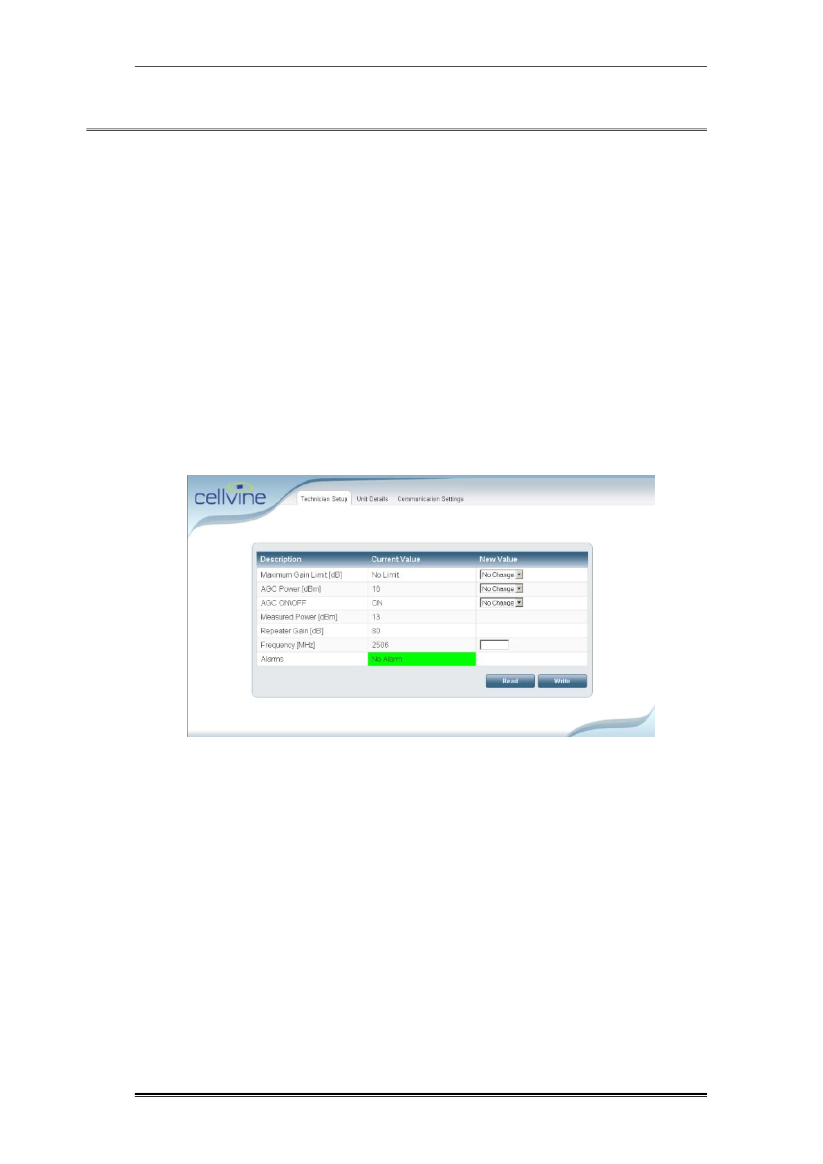
5.1 TECHNICIAN SETUP SCREEN
Figure 20: Technician Setup Screen
Use the drop down menus to change values.
After modifying a value, click on the Write button to send the new value
to the repeater. Only one value can be changed at a time.
Read button – reads current values from the repeater and updates the
screen.
Write button – writes the modified value to the repeater and updates the
screen.
Software Operation Read and write parameters
TDD Mini Repeater: BDA-TDD-25-16-19-AA, Rev 2.2 Oct. 2008 © 2008 all rights reserved. Page 34
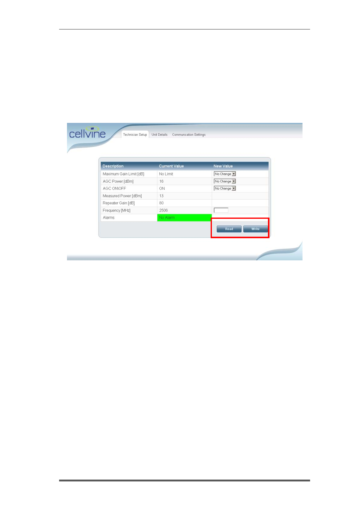
5.2 READ AND WRITE PARAMETERS
After configuring/modifying values, click on the Write button to apply the new
values.
To display the current repeater parameter values, click on the Read button. The
parameters are continually updating, but the new values are only displayed after
you click the Read button.
Figure 21: Technician Setup Screen – Read/Write buttons
Software Operation Technicien setup - Variable Parameter Description
TDD Mini Repeater: BDA-TDD-25-16-19-AA, Rev 2.2 Oct. 2008 © 2008 all rights reserved. Page 35
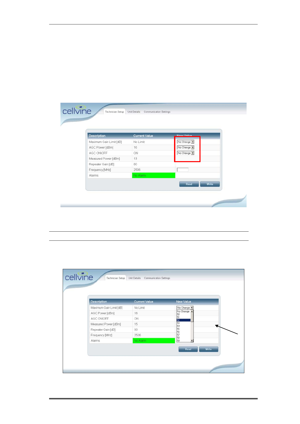
5.3 TECHNICIEN SETUP - VARIABLE PARAMETER DESCRIPTION
The following parameter’s values can are configurable:
Maximum Gain limit
AGC power
AGC ON/OFF
Frequency
Figure 22: Technician Setup Screen –New Value fields
5.3.1 Maximum Gain Limit
Can be set only in AGC ON mode
You can determine the maximum Gain level that the repeater will reach in the
automatic Gain control. Usually, the default value is the maximum repeater Gain,
taking into consideration the isolation between antennas.
Figure 23: Technician Setup Screen – Gain Limit setup
Software Operation Technicien setup - Variable Parameter Description
TDD Mini Repeater: BDA-TDD-25-16-19-AA, Rev 2.2 Oct. 2008 © 2008 all rights reserved. Page 36
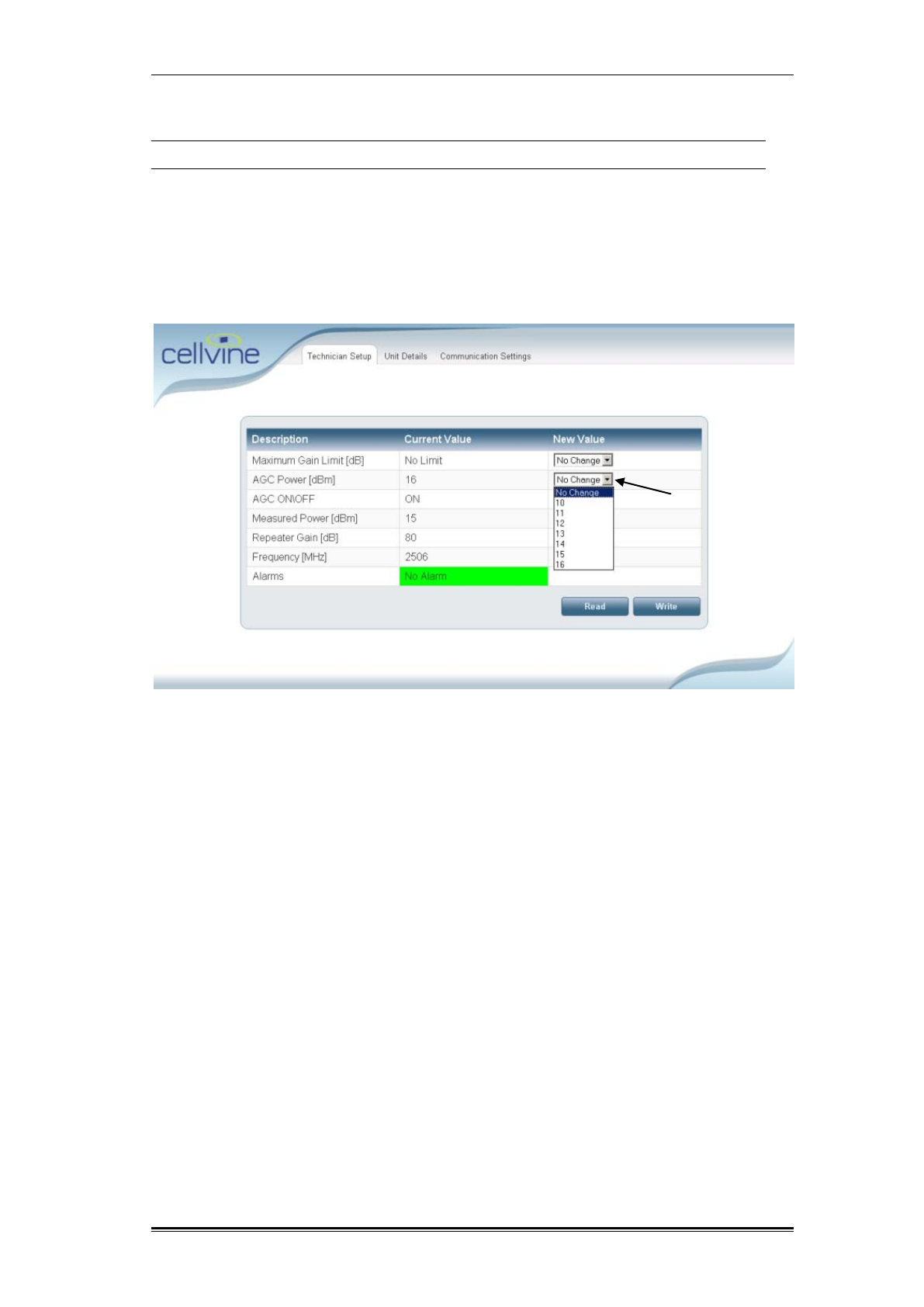
5.3.2 AGC Power
Can be set only in AGC ON mode
The AGC level is the power level that the automatic Gain control will try to
achieve by changing the Gain of the repeater. This level is usually set to the
repeater's maximal linear power. You can determine the level in dBm of the AGC
automatic mechanism in the output power range of 10 dBm to 16 dBm.
Example: If 16 dBm is set in AGC ON mode, the repeater will increase or
decrease the Gain in order to achieve a permanent output power of 16 dBm.
Figure 24: Technician Setup Screen –AGC setup
Software Operation Technicien setup - Variable Parameter Description
TDD Mini Repeater: BDA-TDD-25-16-19-AA, Rev 2.2 Oct. 2008 © 2008 all rights reserved. Page 37
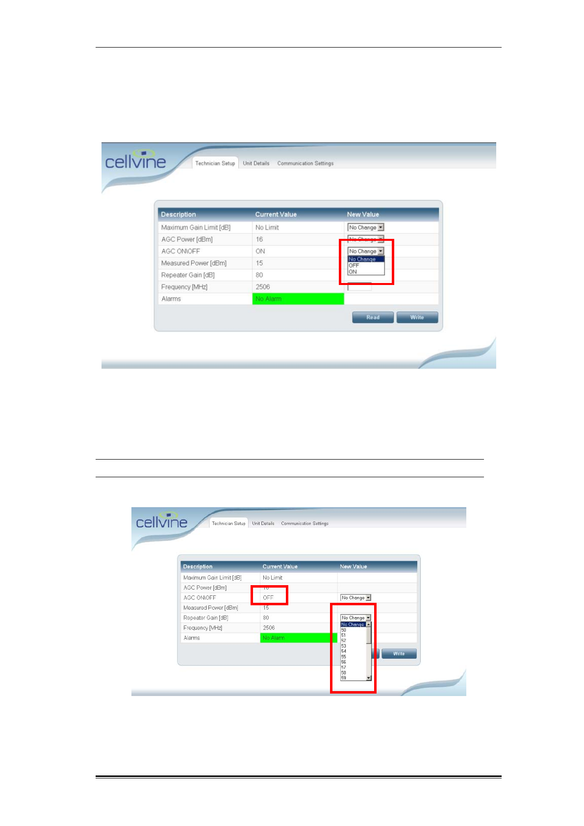
5.3.3 AGC ON/OFF
Set the AGC ON/OFF mode. You can also control the AGC manually from the
panel using the AGC ON/OFF switch. (Please refer to AGC OFF-Operation
Mode, page 26).
Figure 25: Technician Setup Screen –AGC On/Off setup
5.3.4 Repeater Gain
Can be set only in AGC OFF mode.
You can set a fixed level of the desired Gain in the Forward path link (downlink).
Figure 26: Technician Setup Screen –Fixed Gain setup
Software Operation Parameter value readouts
TDD Mini Repeater: BDA-TDD-25-16-19-AA, Rev 2.2 Oct. 2008 © 2008 all rights reserved. Page 38
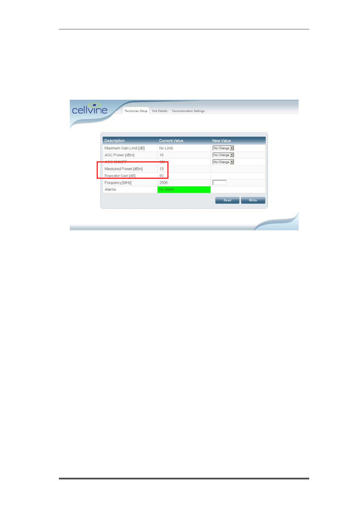
5.4 PARAMETER VALUE READOUTS
Measured Power dBm - The Power Parameters display the current forward
output power of the repeater.
Repeater Gain – The repeater Gain Parameters display the current Gain of the
repeater, and changes in Gain according to the AGC level.
Figure 27: Technician Setup Screen – Parameter values
Software Operation Parameter value readouts
TDD Mini Repeater: BDA-TDD-25-16-19-AA, Rev 2.2 Oct. 2008 © 2008 all rights reserved. Page 39
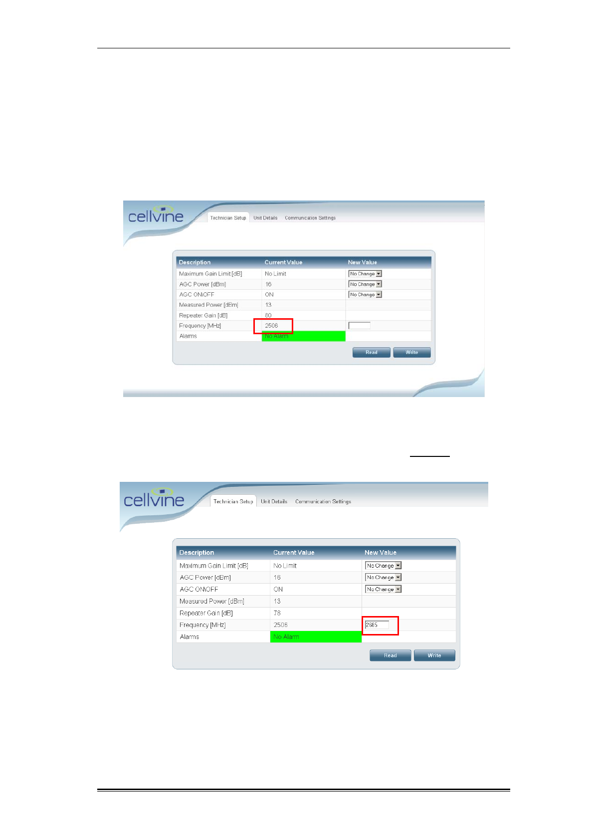
5.4.1 Filter center frequency location adjustment
One of Cellvine TDD repeater's most advanced features is the customization of
the filter center location in the entire TDD band 2500-2690 MHz.
To set the filter center location:
1. Click the Write button.
2. Look at the Current Value column window and verify the current center
Frequency
Figure 28: Technician Setup Screen – Frequency values
3. Enter the new center frequency in the New Value window in 200 Khz
increments, and click Write.
Figure 29: Technician Setup Screen – Adjusting frequency values
Software Operation Parameter value readouts
TDD Mini Repeater: BDA-TDD-25-16-19-AA, Rev 2.2 Oct. 2008 © 2008 all rights reserved. Page 40
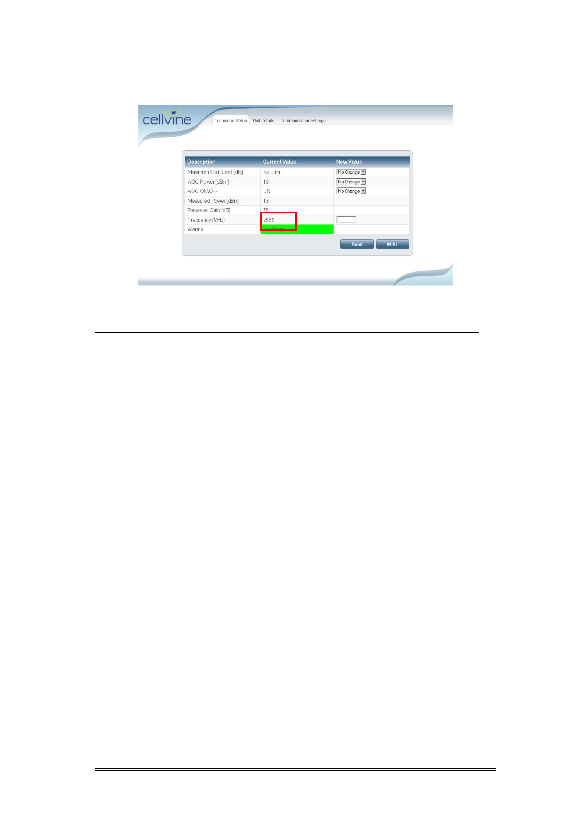
4. Make sure that the new frequency value has changed (in the Current Value
column).
Figure 30: Technician Setup Screen – Frequency values
Note: The filter center location remains as it was at the last location setup,
also after a power loss to the unit.
The factory setting for the current Filter location is 2685 Mhz
Software Operation Unit Details
TDD Mini Repeater: BDA-TDD-25-16-19-AA, Rev 2.2 Oct. 2008 © 2008 all rights reserved. Page 41
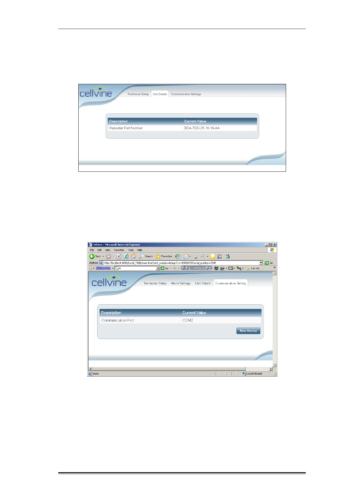
5.5 UNIT DETAILS
This screen displays details of the repeater, such as repeater part number
(model) and its serial number (optional).
Figure 31: Unit Details Screen
5.6 COMMUNICATION SETTINGS
This screen indicates serial port to which the repeater is connected, and allows
switching to another device by clicking on the New Device button.
Figure 32: Communication Settings Screen
To switch to another device, click on the New Device button. The Technician
Setup screen will be open, as shown in Figure 20.
Alarms and Protection Mechanisms Low Signal Alarm
TDD Mini Repeater: BDA-TDD-25-16-19-AA. Rev 2.2 Oct. 2008, © 2008 all rights reserved. Page 42
6 ALARMS AND PROTECTION MECHANISMS
Cellvine TDD Mini repeater is equipped with several alarms and smart protection
mechanisms that provide alerts, and protect the repeater and the cellular
network.
This section describes the default alarms and protection mechanisms.
The alarms are indicated in two ways:
1. LED indication on the side panel of the repeater. For detailed description of
LEDs alarm indications please see Alarm LEDs indications, page 45.
2. On the Cellvine application screen, in the Alarms Current Value column of the
Technician Setup screen.
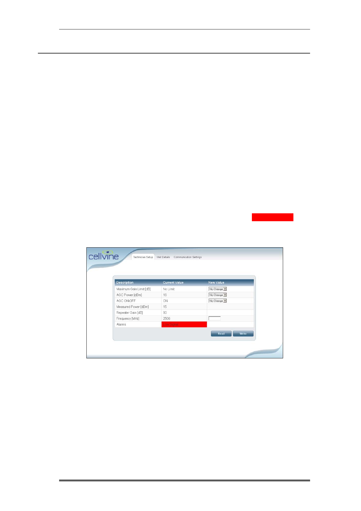
6.1 LOW SIGNAL ALARM
The Low Signal Alarm indicates that the incoming signal on the Forward path
(from the BTS) is low, and the repeater is not performing at maximum efficiency.
The alarm is triggered when the value of the forward power is 3 dBm lower than
the AGC power parameter setup.
Example: The AGC power is set to 16 dBm and the Forward Power readout in
the "Measured Power" parameter screens, is less the 13 dBm. A "Low Signal"
alarm notification appears in the application window.
Figure 33: Low Signal alarm
Alarms and Protection Mechanisms Over-power alarm - High Signal Protection
TDD Mini Repeater: BDA-TDD-25-16-19-AA, Rev 2.2 Oct. 2008 © 2008 all rights reserved. Page 43
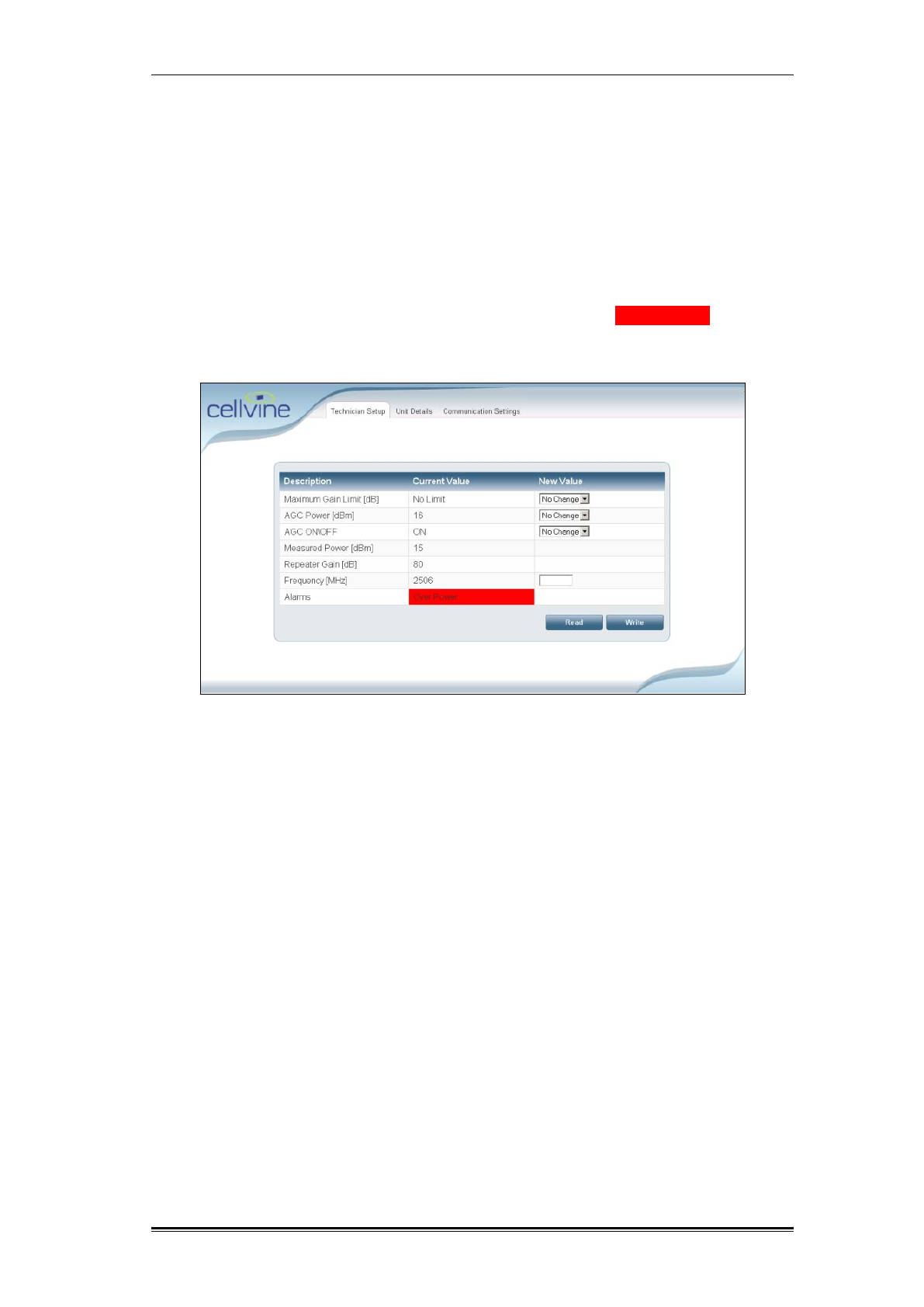
6.2 OVER-POWER ALARM - HIGH SIGNAL PROTECTION
The Overpower mechanism and alarm protects the repeater from unexpected
burst of high RF signal, avoiding damage to the repeater and the cellular
network.
The alarm is triggered when a high signal is detected at the input of the repeater.
An automatic Gain attenuation will reduce the Gain with up to 30 dB.
If after the maximum Gain reduction is applied, the output power of the repeater
is at least 1 dB higher than the "AGC Power" parameter, an "Over Power"
alarm notification appears in the application window.
Figure 34: Overpower alarm
Alarms and Protection Mechanisms Power Amplifier Shutdown Protection
TDD Mini Repeater: BDA-TDD-25-16-19-AA, Rev 2.2 Oct. 2008 © 2008 all rights reserved. Page 44
6.3 POWER AMPLIFIER SHUTDOWN PROTECTION
The repeater PA shuts down when the repeater automatic Gain control reduces
the repeater Gain by 30 dB (maximum reduction), but the incoming signal is still
very high and the output power is above the AGC Power parameter in 4 dB.
After a few seconds, the repeater controller shuts down the power amplifier.
The default setting for shutdown duration is 12 seconds, after which the PA will
restart.
Note: When Shutdown occurs, the continuous alarm reading is not displayed
on the GUI screen, due to power loss.
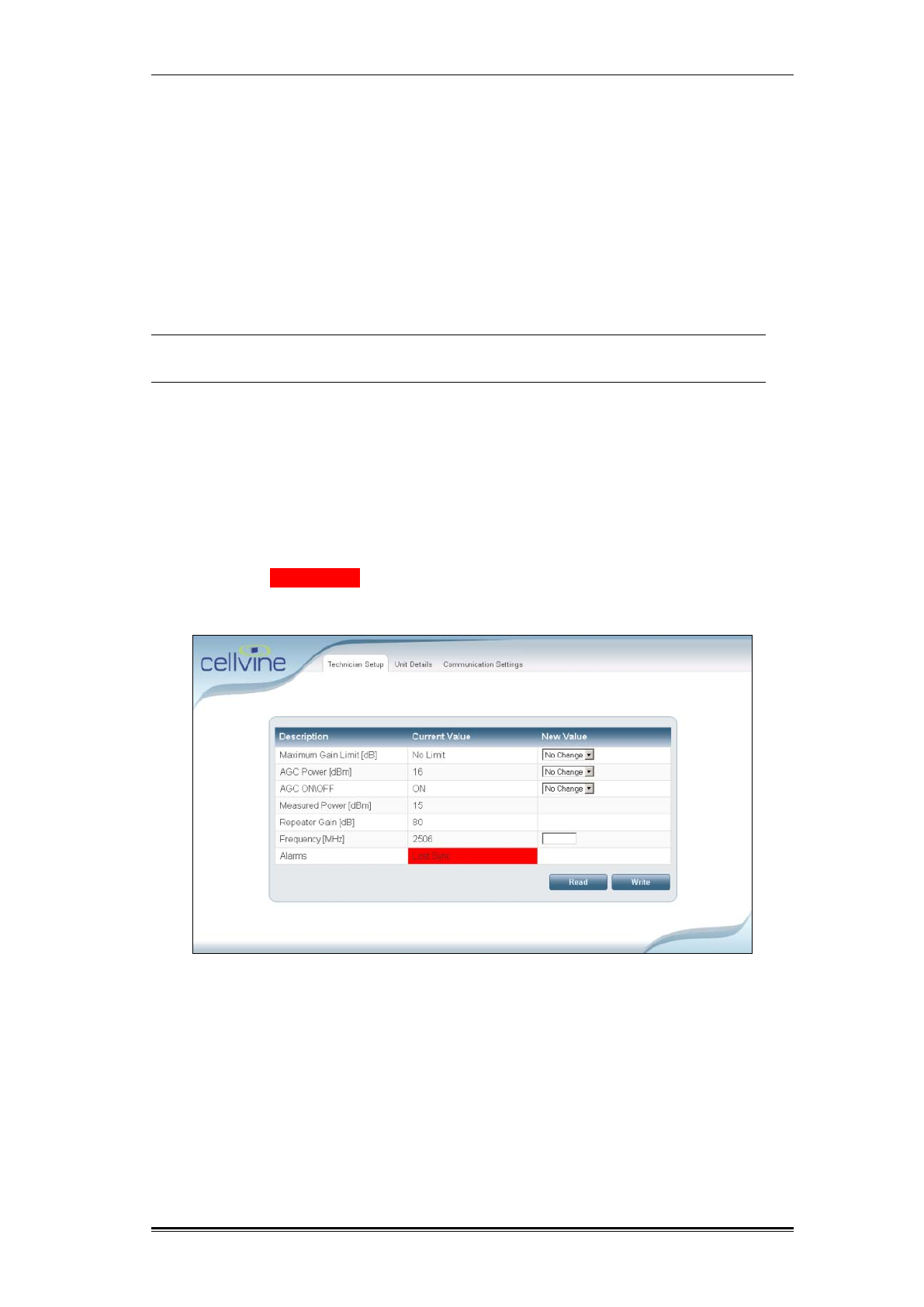
6.4 SYNCHRONIZATION PCMCIA MODEM
To enhance the TDD Cellular network, the repeater modem must receive a
synchronization signal from the Donor BTS at all times.
When the synchronization signal is lost, the repeater will stop enhancing the
network until the synchronization signal is received again by the modem.
In this case, a "Lost Sync" alarm notification appears in the application window.
Figure 35: Lost Sync alarm
Alarms and Protection Mechanisms Alarm LEDs indications
TDD Mini Repeater: BDA-TDD-25-16-19-AA, Rev 2.2 Oct. 2008 © 2008 all rights reserved. Page 45
6.5 ALARM LEDS INDICATIONS
OFF BLINK STEADY ON LED Status Alarm
*
YELLOW
GREEN
Normal
Operation
RED
YELLOW
GREEN Low signal
RED
YELLOW
GREEN Overpower
RED
YELLOW
GREEN
Amplifier
Shutdown
RED
YELLOW
GREEN
lost Sync
RED
Table 7: Alarm LEDs indications
Note: *- in normal operation the yellow Led might blink if donor signal
level will be lower then -67 dBm

Alarms and Protection Mechanisms Exiting the Program
TDD Mini Repeater: BDA-TDD-25-16-19-AA, Rev 2.2 Oct. 2008 © 2008 all rights reserved. Page 46
6.6 EXITING THE PROGRAM
To exit the program, first close the Internet Explorer window, and then click the
“X” button at the corner of the console window.
A message will be displayed, informing you that Windows cannot close the
program.
Ignore the message; the program will close itself after a few seconds.