CeoTronics CT-DECT-H24 DECT Headset User Manual HEADS US ZUL
CeoTronics AG DECT Headset HEADS US ZUL
Contents
- 1. users manual
- 2. revised users manual
revised users manual
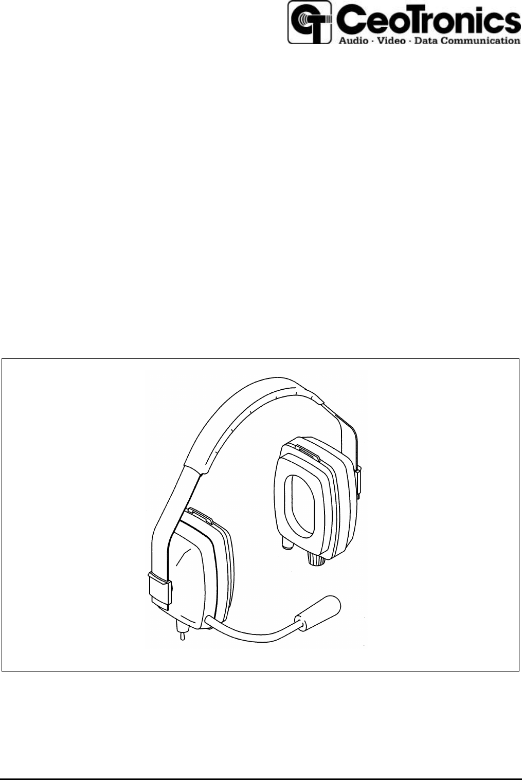
CT-DECT
Headset for Wireless Duplex Communication
Operating Instructions

2
Contents
1. Important safety instructions.....................................................................................................................3
2. Description .................................................................................................................................................5
2.1 General...................................................................................................................................................5
2.2 Power supply and operating time .........................................................................................................6
2.3 Audio signals used.................................................................................................................................6
2.4 Sidetone..................................................................................................................................................6
2.5 On/Off switch for the microphone.........................................................................................................6
3. On-air subscription.....................................................................................................................................6
3.1 General...................................................................................................................................................6
3.2 On-air subscription.................................................................................................................................7
3.2.1 On-air subscription of the first standard headset ............................................................................7
3.2.2 On-air subscription of the second standard headset......................................................................7
4. Commissioning and operation.................................................................................................................7
4.1 Putting on the headset and adjusting the microphone .......................................................................7
4.2 Wearing the headset with an additional head strap............................................................................8
4.3 Switching on, synchronization, adjusting the speaker volume...........................................................8
4.4 Connection setup and release..............................................................................................................9
4.4.1 Connection setup and release by the standard headset................................................................9
4.4.2 Connection setup and release by the base headset.....................................................................10
4.5 End of operation...................................................................................................................................10
5. Headset with level-limited ambient sound reception ............................................................................10
5.1 General.................................................................................................................................................10
5.2 Operator control...................................................................................................................................11
6. Headset with radio set connection.........................................................................................................11
7. Headset muffs for helmet fastening .......................................................................................................12
8. Safekeeping – storage ............................................................................................................................12
9. Recharging the batteries.........................................................................................................................13
10. Maintenance.........................................................................................................................................13
10.1 Visual inspection..............................................................................................................................13
10.2 Cleaning............................................................................................................................................13
10.3 Replacing the windshield on the microphone................................................................................14
10.4 Replacing the ear cushions.............................................................................................................14
11. Accessories and consumable parts ...................................................................................................14
3
Important Note
Please note that any changes or modifications not expressly approved by the party
responsible for compliance will void the user’s authority to operate the equipment.
This device complies with part 15 of the FCC Rules. Operation is subject to the following two
conditions: (1) This device may not cause harmful interference, and (2) this device must
accept any interference received, including interference that cause undesired operation.
SAFETY INFORMATION
Your wireless headset transceiver contains a low power transmitter. When transmitting it
sends out radio frequency (RF) signals. In August 1996, the Federal Communications
Commission (FCC) adopted RF exposure guidelines with safety levels for wireless devices.
WARNING
This headset is considered to be a portable device which housing (the ear cushion) operates
in contact with the user's body.
Because of the construction of this headset the internal transmitter and it's antenna is located
in such a way, that a separation distance from the user's body is maintained in compliance
with the FCC's RF Exposure Guidelines.
This device and it's antenna must not be co-located or operating in conjunction with any other
antenna or transmitter.
Use only the internal antenna. Unauthorized antennas, modifications, or attachments could
damage the transmitter and may violate FCC regulations.
1. Important safety instructions
When using CeoTronics products do not fail to comply with the following safety
information:
lBefore using CeoTronics products read completely the appropriate operating instructions. If in doubt,
ask our technical staff.
lIf repair work of any kind needs to be done to CeoTronics products, arrange for it to be performed
only by the company CeoTronics or by a specialized workshop that is authorized by CeoTronics. In
all other cases our warranty and liability for the product shall lapse.
lIf products are operated on a mains voltage, always pull the mains plug out of the mains plug socket
before opening such products (e.g. for servicing purposes) !
lDo not store CeoTronics products outside or in damp ambient conditions. At all times keep them
clean, dry and at normal air humidity. CeoTronics products must not be stored in areas with a
temperature of over +80° C (+176° F), e.g. in the summertime on the parcel shelf of a car. If not
stated otherwise, the following temperature ranges are allowed for CeoTronics products: -10 to
+55° C (+14 to +131° F) for operation, -40 to +80° C (-40 to +176° F) for storage.
lDo not immerse a CeoTronics product into water, if it is not expressly specified for this purpose.
lWhen using CeoTronics products that are equipped with connection leads ensure that the latter do
not get caught up in operational machinery or wheels !
lType-tested muffs with a high degree of passive noise attenuation are used for CeoTronics headsets
with headset muffs. If not stated otherwise, it is our experience that the passive noise attenuation of
the headset muffs is reduced by approx. 3 dB due to the electronics that are integrated into the
headset muffs. As a rule no empirical values are available for non-standard products.

4
At very high noise levels that exceed the passive protective effect of the headset muffs we
recommend that ear plugs be worn as an additional measure. If in doubt, ask your safety officer or
company doctor. Full noise attenuation exists only if the muff padding is in perfect condition. This
should be replaced at the latest after every 6 months of use.
lIn the case of headsets with headset muffs that protect against harmful ambient noise and that are
not equipped with additional electronics for level-limited ambient sound reception, take heed that the
audibility of warning signals, warning calls etc. is also impaired !
lCeoTronics products that are not intrinsically safe (explosion-proof) and therefore have no special
explosion-proof designation must never be operated in potentially explosive environments (e.g.
when refuelling cars, aircraft etc.). Devices that are not explosion-proof can unintentionally trigger off
explosions in such areas !
lIf you are a cardiac pacemaker carrier, before operating a transmitter/receiver ask the manufacturer
of your cardiac pacemaker for information about any impairment that might be caused due to high
frequencies.
lFor safety reasons reception volumes in excess of 85 dB(A) are possible with a whole series of
CeoTronics products. However, these can be regulated by the user. Do not set the volume any
higher than is necessary. A very high volume setting can lead to damaged hearing, particularly if it is
continuous. For high volumes or noise levels wear additional ear plugs. If in doubt, ask your safety
officer or company doctor.
lWhen on board an airplane always keep a transmitter/receiver switched off. Operation of the
transmitter/receiver could affect the safety of the airplane and it is therefore prohibited. Never
operate electronic devices on board an airplane without the express approval of an authorized
member of the cabin crew.
lDo not leave CeoTronics products lying around loose in cars, e.g. on the parcel shelf. Stow these
products in a suitable, safe place in the car so that they do not present a danger to you or to other
occupants of the car, if emergency braking is effected.
lWhen driving a car, do not use the radio because it may distract you from the other traffic. Never use
a CeoTronics product that will impair your hearing.
lTransmit only when it is necessary. Unnecessarily occupying a channel can prevent the transmission
of vitally important information.
lCharge rechargeable batteries only with the appropriate suitable CeoTronics charger. Observe the
voltage and currency specifications, including those on the mains face (e.g. 230 V AC or 115 V AC).
Never use the charger to recharge non-rechargeable batteries.
lWhen handling rechargeable batteries comply with environmental protection regulations !
Rechargeable batteries contain toxic chemicals (e.g. cadmium). Never attempt to open a
rechargeable battery and never throw a rechargeable battery into fire. Expended (defective)
rechargeable batteries are subject to compulsory regulated waste disposal. Do not put them in the
household waste !
lEnsure that a short-circuit (risk of fire or injury) is not created across rechargeable battery terminals
or charging sockets by a short-out (bent-open paper clip, bunch of keys etc.). In such an event the
warranty shall lapse. Transport any spare rechargeable batteries in an electrically non-conducting
package in order to avoid short-circuiting the rechargeable batteries.
lKeep CeoTronics products and rechargeable batteries out of the reach of children and any other
persons who are not familiar with the handling and operation thereof.
lPackaging materials, e.g. filling materials and plastic bags are not toys and have to be kept out of
the reach of children. There is a risk of children ingesting them and choking !
lSafe operation requires clean devices. Ensure that the devices (microphones, connectors etc.) are
clean and in good condition at all times.
lCeoTronics products may only be used for the specific application envisaged.
lIf the device is to be put out of operation definitively, bring it to a local recycling plant for disposal or
send it to CeoTronics.
5
2. Description
2.1 General
The headset is a transmitter/receiver for wireless duplex voice and data communication between a
max. of three communication parties over short distances. The range depends on the local
circumstances. Up to two standard headsets can log into a base headset. Channel selection is effected
automatically by the unit.
The headset protects against harmful ambient noise and renders possible communication in noisy
environments. The headset microphone is noise-compensating und is equipped with a flexible swan-
neck and windshield. The microphone can be switched on and off by means of a switch at the bottom of
the right-hand headset muff.
The minimum version of the system comprises a base headset and one standard headset. A second
standard headset can also be operated in conjunction with the base headset. The base and standard
headsets are marked by an imprint on the left headset muff, as follows:
– CT-DECT Base
– CT-DECT Standard
èè NOTE
The base headset and the standard headset can also be used in conjunction with other
CeoTronics DECT units. Please take heed of the special CeoTronics operating instructions for
these DECT units.
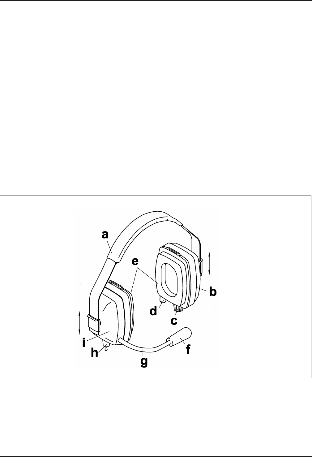
Fig. 1 Headset, basic version
Key to Fig. 1 – Headset, basic version
aAdjustable head band
bLeft headset muff
cOn/Off switch and volume control
dButton for subscription, connection setup
and release
eEar cushions
fMicrophone and windshield
gFlexible swanneck
hOn/Off switch for microphone
iRight headset muff

6
2.2 Power supply and operating time
A 3.6 V/600 mAh rechargeable battery in the right headset muff provides the power supply for the
headset. With a fully charged battery the operating time for continuous operation is approx. 6 hours.
2.3 Audio signals used
Two different tones are used for signalling the operating statuses. The tone for the indication of positive
responses (P-tone) has a higher frequency than the tone for the indication of negative responses (N-
tone). Signalling of the various events is effected by a varying number of consecutive P-tones or N-
tones.
Positive acknowledgement tone
All positive responses are indicated by a high P-tone.
Negative acknowledgement tone and error tone
All negative responses and error statuses are indicated by a low N-tone.
Battery warning
If the battery has an undervoltage a low 3-fold N-tone sequence »N-N-N« sounds approximately every
10 seconds in the headset.
Range warning
If the range limit is reached, a high 3-fold P-tone sequence »P-P-P« sounds approx. every 5 seconds in
the headset.
2.4 Sidetone
The sidetone while speaking is audible in headsets only after interconnection setup between the
headsets (see sections 4.4...4.4.2). Due to this a control is always available as to whether a connection
is active or not.
2.5 On/Off switch for the microphone
The microphone can be switched on and off with the switch »Mic.–OFF–Mic.« (Fig. 1/h) at the bottom of
the right-hand headset muff. Three switch positions are possible. However, communication can only be
performed after subscription (sections 3...3.2.2), switching on, synchronization, adjustment of the
speaker volume (section 4.3) and connection setup (sections 4.4...4.4.2) have all been effected.
Middle position »OFF« (receive): The headset microphone is switched off. You can only receive.
Front switch position »Mic.« (transmit and receive): The headset microphone is switched on. You
can speak into the microphone as long as you hold the switch in this position and simultaneously a
message is being received. After releasing the switch the switch returns to the middle position »OFF«.
Rear »fixed«switch position »Mic.« (transmit and receive): The headset microphone is constantly
switched on. You can speak into the microphone and simultaneously receive a message.
3. On-air subscription
3.1 General
Each headset has its own identification number. First of all an allocation must always take place
between the base headset and the maximum of two standard headsets. This subscription procedure,
which has to be perfomed once only, is performed on the base headset and the maximum of two
standard headsets manually by means of an operator control procedure.
If a base headset or a standard headset is set to subscription mode and this is terminated after
2 minutes without the subscription procedure having been successfully concluded, the data bases of
stored standard headsets available on the base headset and in the case of the standard headset the
available data base for the stored base headset are deleted (»Time Out«).
Once the subscription procedure has been successfully concluded, the identity of the calling party is
stored in the data base of the headset. The standard headset stores a base headset. The base headset
stores the last two successfully subscribed standard headsets, a repeat subscription being permitted.

7
If a third standard headset is subscribed into the base headset, the standard headset that was
subscribed in next to last is deleted from the data base of the base headset.
èè NOTE
The base headset and the standard headset can also be used in conjunction with other
CeoTronics DECT units. The on-air subscription of a headset to one of these DECT units is
carried out analogous and in the sequence as described in sections 3.2....3.2.2. Going to do so,
first ascertain which of the DECT units is the base unit (lettering »CT-DECT Base«) and which a
standard unit (lettering »CT-DECT Standard«). For on-air subscription at a DECT unit always the
on/off switch and the push-button » )) « for subscription, connection setup and release are
used.
Please take heed of the special CeoTronics operating instructions for the DECT unit.
3.2 On-air subscription
èè NOTE
Two standard headsets can never be simultaneously subscribed into the base headset, they
must always be subscribed one after the other. For subscription the base headset must always
be switched on before the standard headset.
3.2.1 On-air subscription of the first standard headset
On the base headset press the push-button » ) « (Fig. 1/d) and switch on the base headset by means
of the On/Off switch and volume control (rotary knob Fig. 1/c). After switching on keep the button » ) «
pressed for at least 10 seconds.
On the standard headset press the push-button » ) « (Fig. 1/d) and switch on the standard headset by
means of the On/Off switch and volume control (rotary knob Fig. 1/c). After switching on keep the
button » ) « pressed for at least 10 seconds. The standard headset has to be switched on within 2
minutes of the base headset being switched on, otherwise a »Time Out« may occur (see section 3.1).
After approx. 30 seconds a high double-beep tone can be heard both in the base headset and in the
standard headset. This indicates that the on-air subscription has been successfully completed. A
second high double-beep tone finally reports that the standard headset has synchronized itself with the
base headset.
3.2.2 On-air subscription of the second standard headset
Switch off (position »OFF«) the base headset and, if it is switched on, the second standard headset by
means of the On/Off switch and volume control (rotary knob Fig. 1/c).
Repeat the subscription procedure as described in section 3.2.1 for the base headset and for the
second standard headset.
4. Commissioning and operation
4.1 Putting on the headset and adjusting the microphone
a. Put on the headset. Adjust the headset muffs by sliding the headband so that the muff padding fully
encloses your ears and so that the headband is lying on the centre of your head. Only then is the
best possible noise attenuation provided.
For hygienic reasons we recommend that you use washable perspiration absorbers made of cotton
for the headset. These are pulled over the muff padding, making them comfortable to wear.
CAUTION
Do not »twist« the flexible swanneck. Do not carry the headset by the swanneck.
Use the microphone only with a windshield.
8
b. Adjust the flexible swanneck so that the microphone is located at a distance of approx. 5 mm
(0.2 in.) in front your lips. Optimum voice transmission with the best possible noise compensation is
then provided.
4.2 Wearing the headset with an additional head strap
In the event of fast body movements or extreme body postures or if you are using a protection helmet
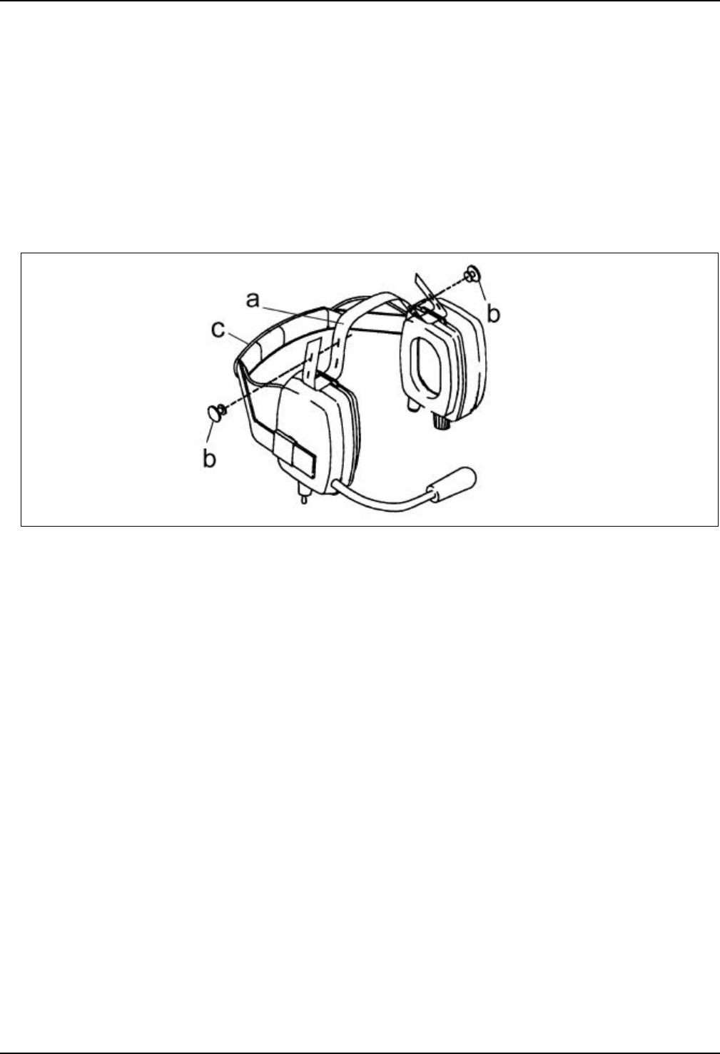
the headset can be fixed to your head additionally by means of the head strap provided (Fig. 2/a).
a. Pull the headstrap as per Fig. 2 through the slit in the headset muffs and fasten it with the two
retainers (Fig. 2/b).
b. Put on the headset, fold the head band (Fig. 2/c) to the rear and wear the head band as a neck
band. Ensure that the head strap and neck band are tautly seated.
Fig. 2
4.3 Switching on, synchronization, adjusting the speaker volume
a. The rotary knob for switching the headset On/Off and for adjusting the speaker volume is located at
the bottom of the left-hand headset muff. The headset is switched off in position »OFF«. Switch on
the base headset and then the standard headset by means of the On/Off switch and volume control
(rotary knob).
èè NOTE
The push-button » )) « (Fig. 1/d) must not be pressed until the headsets are synchronized
with each other.
Synchronization: A click is audible in the base and in the standard headset roughly 10 seconds
after switching on. The synchronization procedure then begins, i.e. the standard headset seeks its
base headset. This synchronization procedure can last approx. 30 seconds. Upon completion of
synchronization – i.e. the standard headset has found its base headset – a high double-beep tone
sounds in the standard and in the base headset, indicating that the standard and the base headset
are ready for operation. In the case of two standard headsets two high double-beep tones are
audible in the base headset upon successful completion of synchronization.
b. On voice reception adjust the speaker volume for your headset by means of the On/Off switch and
volume control (rotary knob).
èè NOTE
Always leave the headsets switched on for the usage duration of the headsets so that
immediate operating standby and availability of the headsets are provided.
c. Connection setup and release see sections 4.4...4.4.2.

9
4.4 Connection setup and release
èè NOTE
The base headset and the standard headset can also be used in conjunction with other
CeoTronics DECT units. The connection setup and release for the units is carried out basically
as described in sections 4.4.1, 4.4.2. Going to do so, first ascertain which of the DECT units is
the base unit (lettering »CT-DECT Base«) and which a standard unit (lettering »CT-DECT
Standard«). For the connection setup and release at a DECT unit always the push-button » )) «
is used.
Please take heed of the special CeoTronics operating instructions for the DECT unit.
4.4.1 Connection setup and release by the standard headset
(1) Prerequisites
ŸHeadsets subscribed (sections 3...3.2.2)
ŸHeadsets switched on and synchronized (section 4.3)
(2) Two-party conference
Connection setup: Briefly press the push-button » ) « on the left-hand side of the headset muff of
your standard headset. When the connection is set up a high beep tone sounds in the calling standard
headset and in the called base headset. Subsequently duplex communication (speech and
simultaneous listening) is possible for both parties.
The microphone must be switched on in order to speak (see section 2.5). When the connection is active
a sidetone is audible in the headset while speaking. This is for the purpose of control.
Connection release: Briefly press the push-button » ) « on the left-hand side of the headset muff of
your standard headset. The standard headset is disconnected from the base headset. To conclude a
high beep tone then sounds in the standard headset and in the base headset. The standard headset
and base headset are now on standby.
(3) Three-party conference
Below the designations standard headset 1 and standard headset 2 are used only for the purpose of
better differentiation in the operating instructions. Both the standard headsets operate with equal
entitlement.
Connection setup: Briefly press the push-button » ) « on the left-hand headset muff of your standard
headset 1. Standard headset 1 sets up a connection with the active base headset. Upon setup of the
connection a high beep tone sounds in standard headset 1 and in the called base headset.
The base headset does not automatically set up a connection with standard headset 2. Not until the
push-button » ) « has been pressed on standard headset 2 does standard headset 2 set up a
connection with the base headset. If a connection exists between standard headset 1 and the base
headset, the base headset then switches over automatically to three-party conference mode.
If a connection already exists between standard headset 2 and the base headset when standard
headset 1 sets up a connection with the base headset, the connection between standard headset 2 and
the base headset is retained and the base headset switches over automatically to three-party
conference mode.
The microphone must be switched on in order to speak (see section 2.5). When the connection is active
a sidetone is audible in the headset while speaking. This is for the purpose of control.
Connection release: Briefly press the push-button » ) « on the left-hand headset muff of your
standard headset 1. The standard headset 1 disconnects itself from the base headset. This procedure
is acknowledged by a high beep tone in standard headset 1 and in the base headset. If a connection
still exists at this time between the base headset and standard headset 2, the connection between the
base headset and standard headset 2 is retained. Not until the push-button » ) « on standard headset
2 is pressed briefly does standard headset 2 disconnect itself from the base headset and the three
headsets are on standby.

10
4.4.2 Connection setup and release by the base headset
(1) Prerequisites
ŸHeadsets subscribed (sections 3...3.2.2)
ŸHeadsets switched on and synchronized (section 4.3)
(2) Two-party conference
Connection setup: Briefly press the push-button » ) « on the left-hand side of the headset muff of
your base headset. When the connection is set up a high beep tone sounds in the calling base headset
and in the called standard headset. Subsequently duplex communication (speech and simultaneous
listening) is possible for both parties.
The microphone must be switched on in order to speak (see section 2.5). When the connection is active
a sidetone is audible in the headset while speaking. This is for the purpose of control.
Connection setup: Briefly press the push-button » ) « on the left-hand side of the headset muff of
your base headset. The base headset disconnects itself from the standard headset. A high beep tone
then sounds in the base headset and in the standard headset. The base headset and standard headset
are now on standby.
(3) Three-party conference
Below the designations standard handset 1 and standard headset 2 are used only for the purpose of
better differentiation in the operating instructions. Both standard headsets operate with equal
entitlement.
Connection setup: Briefly press the push-button » ) « on the left-hand headset muff of your base
headset. The base headset sets up automatically a connection with the active standard headsets 1 and
2. Upon setup of the connection a high beep tone sounds in the calling base headset and in the called
standard headsets 1 and 2, and the base headset switches over automatically to three-party
conference mode.
The microphone must be switched on in order to speak (see section 2.5). When the connection is active
a sidetone is audible in the headset while speaking. This is for the purpose of control.
Connection release: Briefly press the push-button » ) « on the left-hand headset muff of your base
headset. The base headset disconnects itself from the standard headsets 1 and 2. This procedure is
acknowledged by a high beep tone in the base headset and in the standard headsets 1 and 2. The
three headsets are now on standby.
4.5 End of operation
Switch off the Headset with the ON/OFF switch and volume control knob (switch position OFF). This
guarantees a longer usage from the rechargeable battery. If necessary recharge the headset battery.
5. Headset with level-limited ambient sound reception
5.1 General
The headset with level-limited ambient sound reception (ASR) (Fig. 3) is used mainly where ambient
sounds, warning signals etc, have to be heard perfectly alongside voice communication.
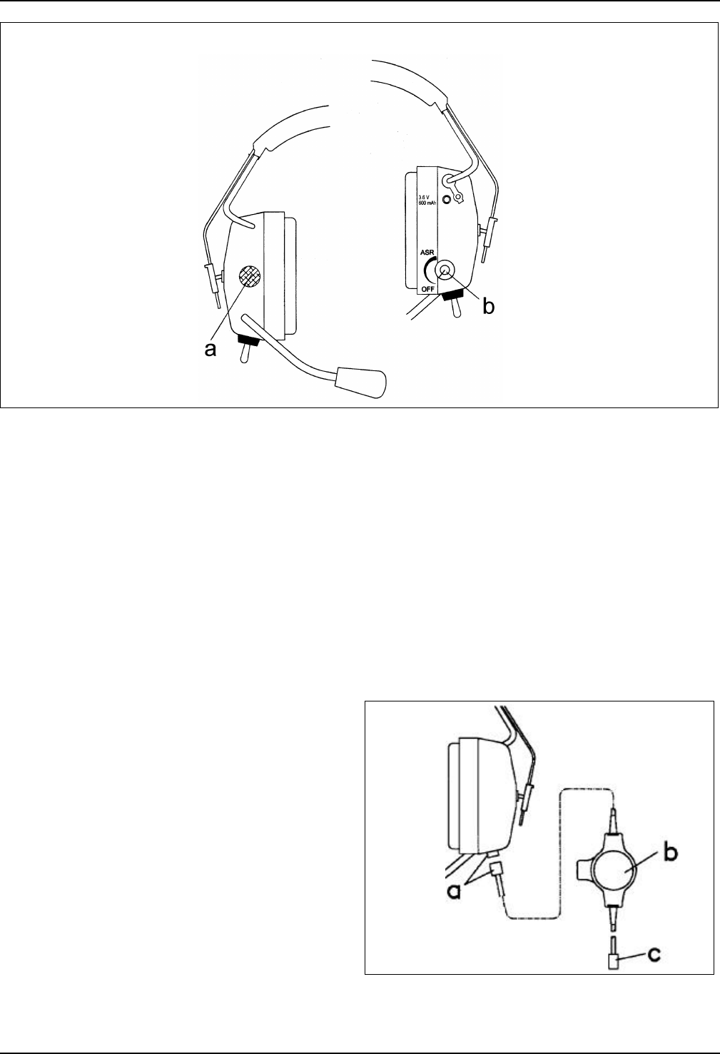
With ASR, ambient sounds can be received via a second microphone (Fig. 3/a) on the front side of the
right-hand headset muff and can be heard via one ASR speaker each in the right-hand and left-hand
headset muffs. The hearing of voice communication is also effected via one speaker each in the right-
hand and left-hand headset muffs. Even when receiving a message the external sound reception is in
operation.
11
Fig. 3 Headset with level-limited ambient sound reception
In the case of external sound levels of over 85 dB(A) the sound level emitted by the ASR speakers in
the headset muffs to the ear is limited to a maximum of 85 dB(A). The overall noise attenuation of the
headset is, however, limited to passive noise attenuation of the headset muff.
5.2 Operator control
Described below are only the operating control differences relating to external sound reception.
Switch on the ambient sound reception by means of the rotary knob »ASR« (Fig. 3/b) on the rear side
of the right-hand headset muff and adjust by means of this rotary knob the desired volume for the
ambient sound reception. The ambient sound reception is switched off in position »OFF«.
It is possible to use the headset for ambient sound reception only via the separate On/Off switch and
volume control »ASR«.
6. Headset with radio set
connection
Two communication circuits are realizable with the
additional radio set connection (example Fig. 4).
Both the base headset and the standard headset
can be equipped with a radio set connection.
Connection to the radio set is effected via a radio
set adapter which consists as a rule of the
following parts:
–Inline PTT button with fastening clip on the rear
side (Fig. 4/b)
–Connection cable with socket for connection to
the headset (Fig. 4/a)
–Connection cable with radio set plug (Fig. 4/c)
depending on the radio set
Fig. 4

12
Communication circuit 1
Communication between the user of the base headset and a max. of two other users of standard
headsets within the headset frequency range. The standard headsets must have logged into the base
headset.
Communication circuit 2
Communication in connection with an additional radio set on the radio set channel. The radio set is
connected to the headset via the radio set adapter.
Commissioning and operation
Described below are only the differences relating to the additional radio set connection.
a. Insert the plug connection (Fig. 4/a). Connect the radio set adapter via the radio set plug (Fig. 4/c) to
the accessory connection of the radio set. Fasten the inline PTT button (Fig. 4/b) by means of the
clip on the rear side to a suitable place on your clothing. Switch on the radio set and adjust on the
radio set the basic volume for the headset. Take heed of the operating instructions for the radio set
issued by the radio set manufacturer. Switch on the headsets as per section 4.3, wait until the
standard headset has synchronized itself with the base headset and adjust the desired speaker
volume on the headsets.
b. Voice communication circuit 1: See sections 4.4...4.4.2.
c. Voice communication circuit 2: To transmit press the inline PTT button (Fig. 4/b), i.e. in order to
key the radio set transmitter. You can speak into the headset microphone as long as you keep the
key pressed. Upon releasing the key the radio set is back on standby/reception. A message that is
received via the radio set is audible only in the right-hand headset muff of the headset which is
connected to the radio set.
When you press the inline PTT button and speak into the headset microphone, the message
transmission path is dependent on the position of the microphone switch »Mic.–OFF–Mic.«
(Fig. 1/h).
ŸMicrophone switch »Mic.–OFF–Mic.« in middle position »OFF«: The message is transmitted to
the radio set only
ŸMicrophone switch »Mic.–OFF–Mic.« in key position »Mic.« or in the »fixed« switch position
»Mic.«: The message is transmitted to the radio set and to the headset or to the two headsets
with which an active connection setup exists.
7. Headset muffs for helmet fastening
The two headset muffs can be supplied without a head band for lateral fastening to a helmet. Different
fastening parts are available depending on the helmet type. Separate installation instructions are
available for fastening to the helmet, these being provided together with the delivery of the fastening
parts. Lay the connection cable between the two headset muffs in the helmet so that it causes no
annoyance. In addition you can also use the head strap that is provided with each headset (see
section 4.2).
If no noise protection is required for the activity, you can fold the two fastening arms with the headset
muffs outwards and away from the helmet.
8. Safekeeping – storage
Store the cleaned device in a clean, dry place at normal room temperature and in normal relative air
humidity.
13
9. Recharging the batteries
CAUTION
Never use battery chargers to charge non-rechargeable batteries. Never open rechargeable
batteries or throw them into fire. Used (defective) rechargeable batteries are subject to special
waste disposal. Do not put them in the household refuse !
Use a CeoTronics charger (see section 11) to
charge the 3.6 V/600 mAh battery in the headset.
Using other chargers can cause rechargeable
batteries to become damaged. The charging time
of a battery is dependent on the charger you are
using. Separate CeoTronics operating instructions
are available for this purpose.
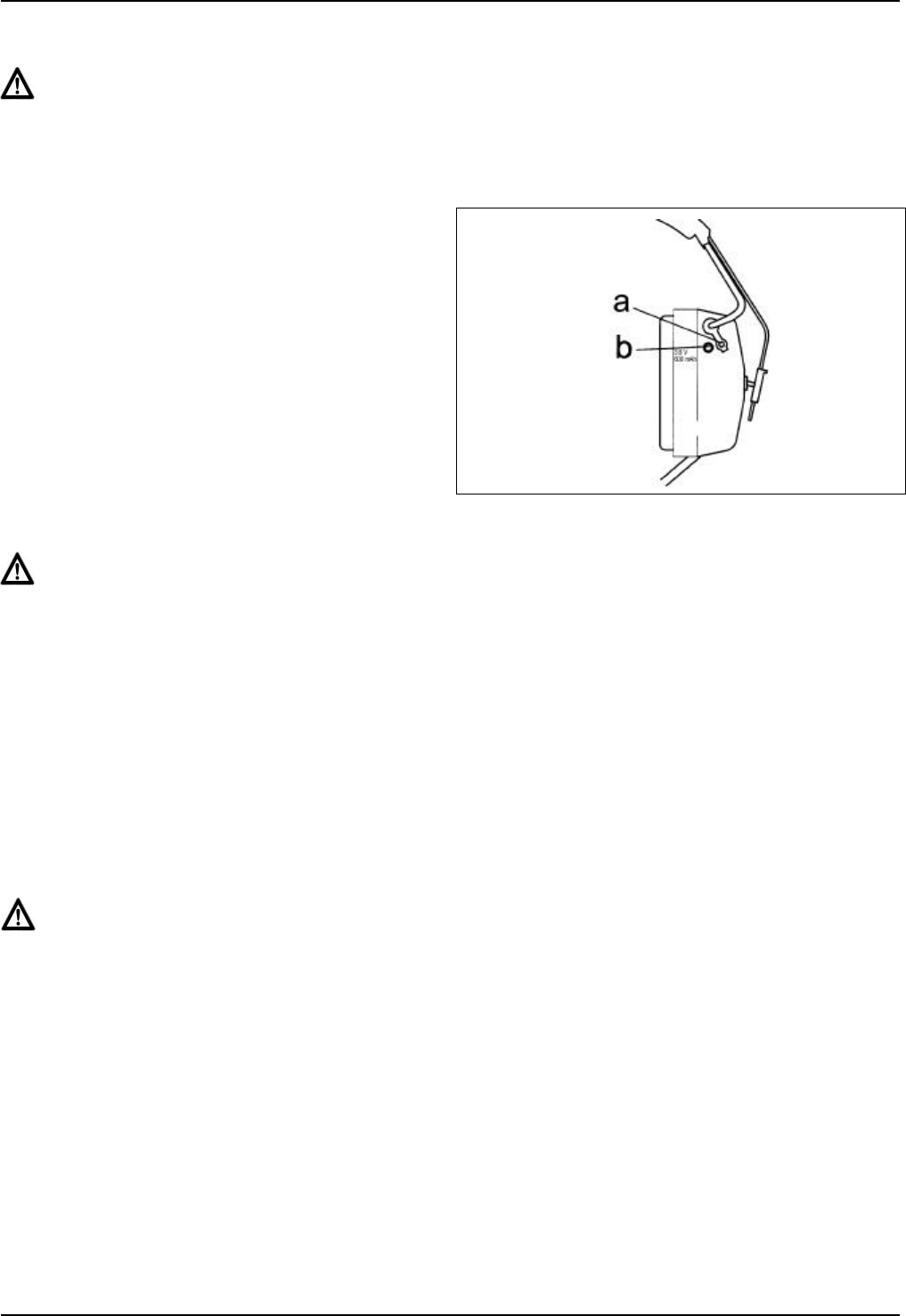
The battery charging socket (Fig. 5/b) is located
on the right-hand headset muff and is sealed with
a stopper (Fig. 5/a). Before connecting the
charger pull the stopper out of the battery
charging socket and re-insert it after recharging.
Fig. 5
WARNING
To recharge the battery always switch off the headset (On/Off switch and volume control in
position »OFF«).
10. Maintenance
10.1 Visual inspection
Regularly examine the headset muffs and in particular the ear cushions for signs of fractures, cracks
and wear. If the headset muffs are damaged, replace them and send them in to CeoTronics for repair.
Replace damaged or worn ear cushions in accordance with section 10.4, and, even if not damaged,
every 6 months of use at the latest.
10.2 Cleaning
WARNING
When cleaning ensure that no moisture penetrates inside the unit. Do not use any solvents
(e.g. benzine, alcohol, etc.) for cleaning purposes !
Remove any loose dust with a soft brush. Clean, if necessary, the outside with a suitable clean cloth
that has been slightly moistened with clear water, and rub the parts dry afterwards. If heavily soiled,
some dishwashing liquid can be used in addition.
14
10.3 Replacing the windshield on the
microphone
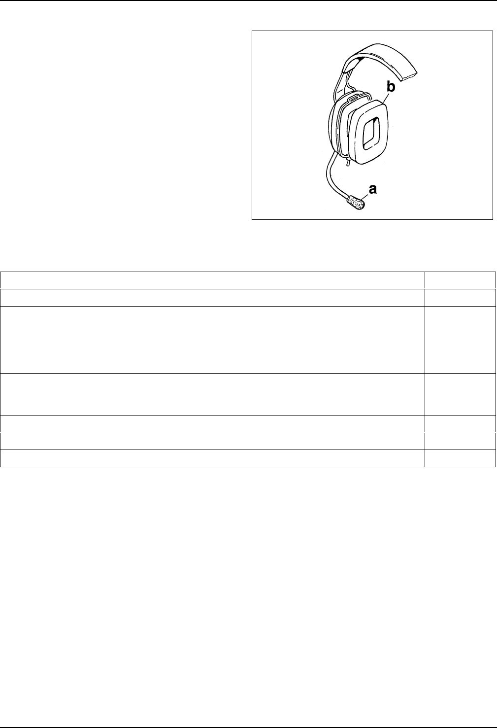
Pull the windshield (Fig. 6/a) off the microphone
and replace it.
10.4 Replacing the ear cushions
Pull the ear cushion (Fig. 6/b) off the headset muff
and replace it. Ensure that the new ear cushion
fully engages.
Fig. 6
11. Accessories and consumable parts
Designation and description Art. No.
Carrying case for transceiver headset, colour grey 40 35 030
Single-unit quick charger, charging time approx. 30 minutes
For a mains voltage of 100...240 V AC and for operation on a car's 12 V DC electrical
system
For a mains voltage of 100...240 V AC and for operation on a car's 12 V DC electrical
system (charger without main cord)
09 10 100
09 10 110
Single-unit plug-in charger, charging time approx. 7 hours
For a mains voltage of 230 V AC. Charger with »Euro« plug (CENELEC standard)
For a mains voltage of 115 V AC mains. Charger with »US« plug (US standard) 40 06 525
40 06 530
Ear cushion, 2 pcs. 50 00 501
Windshield for microphone, 10 pcs. 50 02 201
Comfort set consisting of 50 pcs. (25 pair-pack) sweat absorbing cotton pads 40 10 025