CeoTronics CT-DECTCASE CT-DECT Case User Manual dok1200 gb
CeoTronics AG CT-DECT Case dok1200 gb
Contents
- 1. Manual
- 2. User Manual
Manual
CT-DECT Case (8)
Operating Instructions

2
Contents
1. Technical safety instructions, environment protection, safety at work ...............................................3
2. Description .........................................................................................................................................6
2.1 Technical data ............................................................................................................................7
2.2 Technical description ..................................................................................................................8
3. Operation .........................................................................................................................................11
3.1 First commissioning ..............................................................................................................11
3.1.1 Recharging the NiMH rechargeable batteries....................................................................11
3.1.2 On-air subscription of the CT-DECT device (PP) to the CT-DECT Case (8) (FP).............12
3.2 Commissioning......................................................................................................................15
3.2.1 Connecting the CT-DECT Case (8) to the aircraft.............................................................15
3.2.2 Switching-on of CT-DECT Case (8) and CT-DECT device (PP) .......................................15
3.3 Controls ....................................................................................................................................16
3.4 Operating under special climatic conditions..............................................................................17
4. Maintenance and proper care ..........................................................................................................18
4.1 Visual inspection.......................................................................................................................18
4.2 Cleaning....................................................................................................................................18
4.3 Faults, causes, corrective actions.............................................................................................18
4.4 Storage .....................................................................................................................................18
4.5 Transport and shipping .............................................................................................................19
5. Replacements to be made by the user ............................................................................................19
5.1 Replacing components .............................................................................................................19
5.1.1 CT-DECT Case (8) ............................................................................................................19
3
1. Technical safety instructions, environment protection, safety at work
Important Information for Users of the
CT-DECT transceivers
The CT-DECT transceiver modul has been tested for electromagnetic compatibility and is
compliant with the european DECT-Standard.
CT-DECT transceivers that are not intrinsically safe (explosion-protected) and therefore do
not have any special hazardous duty marking must never be used in potentially explosive
atmospheres. Unprotected CT-DECT transceivers can trigger explosions unintentionally in
these areas.
CeoTronics does not assume any liability for damage to property and personal injuries of any
kind that can arise through the above mentioned or any other incorrect use of the CT-DECT
transceivers.
Important safety instructions
For the use of the device notice the national safety and accident prevention
regulations and the following safety instructions shown in italics in this instruction
manual.
z Before using CeoTronics products read completely the appropriate operating instructions. If in doubt,
ask our technical staff.
z If repair work of any kind needs to be done to CeoTronics products, arrange for it to be performed
only by the company CeoTronics or by a specialized workshop that is authorized by CeoTronics. In
all other cases our warranty and liability for the product shall lapse.
z Do not immerse the radio equipment into water.
z When using CeoTronics products that are equipped with connection leads ensure that the latter do
not get caught up in operational machinery or wheels!
z Radio equipment that are not intrinsically safe (explosion-proof) and therefore have no spe-
cial explosion-proof designation must never be operated in potentially explosive environ-
ments (e.g. when refueling cars, aircraft etc.). Devices that are not explosion-proof can unin-
tentionally trigger off explosions in such areas!
z Connect CeoTronics accessories to a device or disconnect them from a device only when the device
is switched off.
z If you are a cardiac pacemaker carrier, before operating a transmit-
ter/receiver ask the manufacturer of your cardiac pacemaker for informa-
tion about any impairment that might be caused due to high frequencies.
z Before starting to operate the device in sensitive areas like e.g. aboard airplanes or in hospitals etc.,
please check first if it is permitted to use it in these environments.
For use aboard an airplane a Type Certificate (TC) or a Certificate of Nonobjection (CO) must be
available. Should the communication equipment not be homologated, its use aboard an airplane is
strictly prohibited as it could jeopardize the safety of the airplane. Never put electronic devices into
operation aboard an airplane without obtaining prior approval from the cabin crew.
4
z Do not leave the radio equipment products lying around loose in cars, e.g. on the parcel shelf. Stow
these products in a suitable, safe place in the car so that they do not present a danger to you or to
other occupants of the car, if emergency braking is effected.
z When driving a car, do not use the radio because it may distract you from the other traffic.
z Charge rechargeable batteries only with the appropriate suitable charger. Observe the voltage and
currency specifications. Never use the charger to recharge non-rechargeable batteries.
z When handling rechargeable batteries comply with environmental protection regulations !
Never attempt to open a rechargeable battery and never throw a rechargeable battery into
fire. Expended (defective) rechargeable batteries are subject to compulsory regulated
waste disposal. Do not put them in the household waste!
z Ensure that a short-circuit (risk of fire or injury) is not created across rechargeable battery terminals
or charging sockets by a short-out (bent-open paper clip, bunch of keys etc.). In such an event the
warranty shall lapse. Transport any spare rechargeable batteries in an electrically non-conducting
package in order to avoid short-circuiting the rechargeable batteries.
z Keep the radio equipment and rechargeable batteries out of the reach of children and any other per-
sons who are not familiar with the handling and operation thereof.
z Safe operation requires clean devices. Ensure that the devices (microphones, connectors etc.) are
clean and in good condition at all times.
z The radio equipment may only be used for the specific application envisaged.
z Should equipment, supplied by CeoTronics, be definitely put out of service you may return it to
CeoTronics. We ensure recycling and/or disposal of outdated equipment in compliance with
the applicable environment protection law.
z Keep these operating instructions for later use.

5
Important Notes for operation of the CT-DECT System in the USA
Please note that any changes or modifications not expressly approved by the party
responsible for compliance will void the user’s authority to operate the equipment.
This device complies with part 15 of the FCC Rules. Operation is subject to the following two
conditions: (1) This device may not cause harmful interference, and (2) this device must
accept any interference received, including interference that may cause undesired operation.
Note: This equipment has been tested and found to comply with the limits for a Class A digital
device, pursuant to part 15 of the FCC Rules. These limits are designed to provide reasonable
protection against harmful interference when the equipment is operated in a commercial envi-
ronment. This equipment generates, uses, and can radiate radio frequency energy and, if not
installed and used in accordance with the instruction manual, may cause harmful interference
to radio communications. Operation of this equipment in a residential area is likely to cause
harmful interference in which case the user will be required to correct the interference at his
own expense.
NOTE: This equipment has been tested and found to comply with the limits for a Class B
digital device, pursuant to Part 15 of the FCC Rules. These limits are designed to provide
reasonable protection against harmful interference in a residential installation. This equip-
ment
generates, uses and can radiate radio frequency energy and, if not installed and used in
accordance with the instructions, may cause harmful interference to radio communications.
However, there is no guarantee that interference will not occur in a particular installation. If
this equipment does cause harmful interference to radio or television reception, which can be
determined by turning the equipment off and on, the user is encouraged to try to correct the
interference by one or more of the following measures:
. Reorient or relocate the receiving antenna.
. Increase the separation between the equipment and receiver.
. Connect the equipment into an outlet on a circuit different from that to which the receiver is
connected.
. Consult the dealer or an experienced radio/TV technician for help.
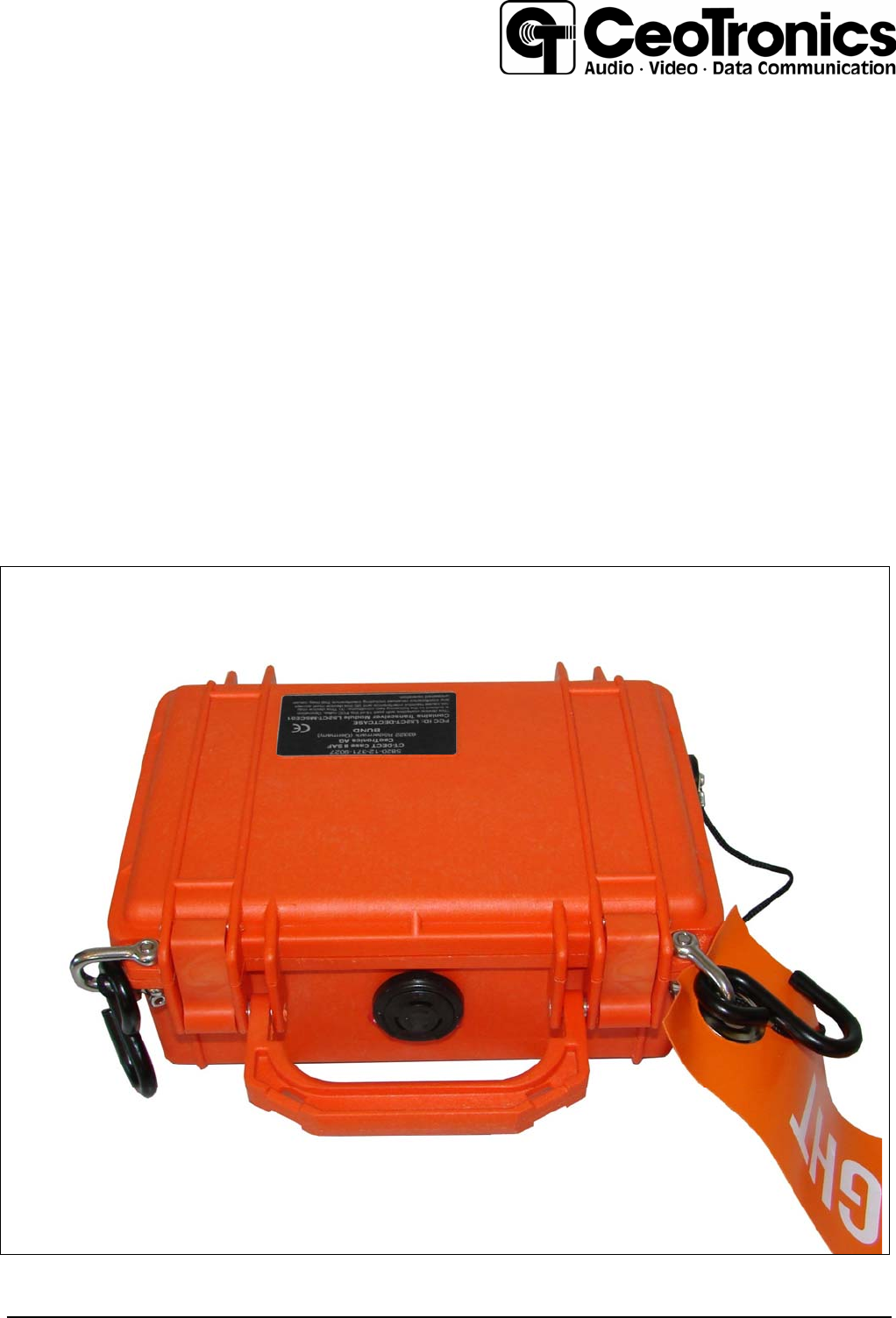
RFExposure mobil:
contains Transceiver Module with FCC ID L52CT-M5CEO1
P the maximum measured power output is 119,67mW (20,78 dBm),
G A0 the maximum antenna gain is 0 dBi = numeric gain 1.
Smax A0 the maximum permissible exposure is defined in 47 CFR 1.1310 with 1 mW/cm².
R A0 the distance of 20cm from the EUT's transmitting antenna where the exposure
level reaches the maximum permitted level
is calculated using the general equation:
S= P*G / 4R² Smax = 0.024mW/cm²,
The internal antenna used for this mobile transmitter must provide a separation distance of at
least 20 cm from all persons and must not be co-located or operating in conjunction with any
other antenna or transmitter.
6
2. Description
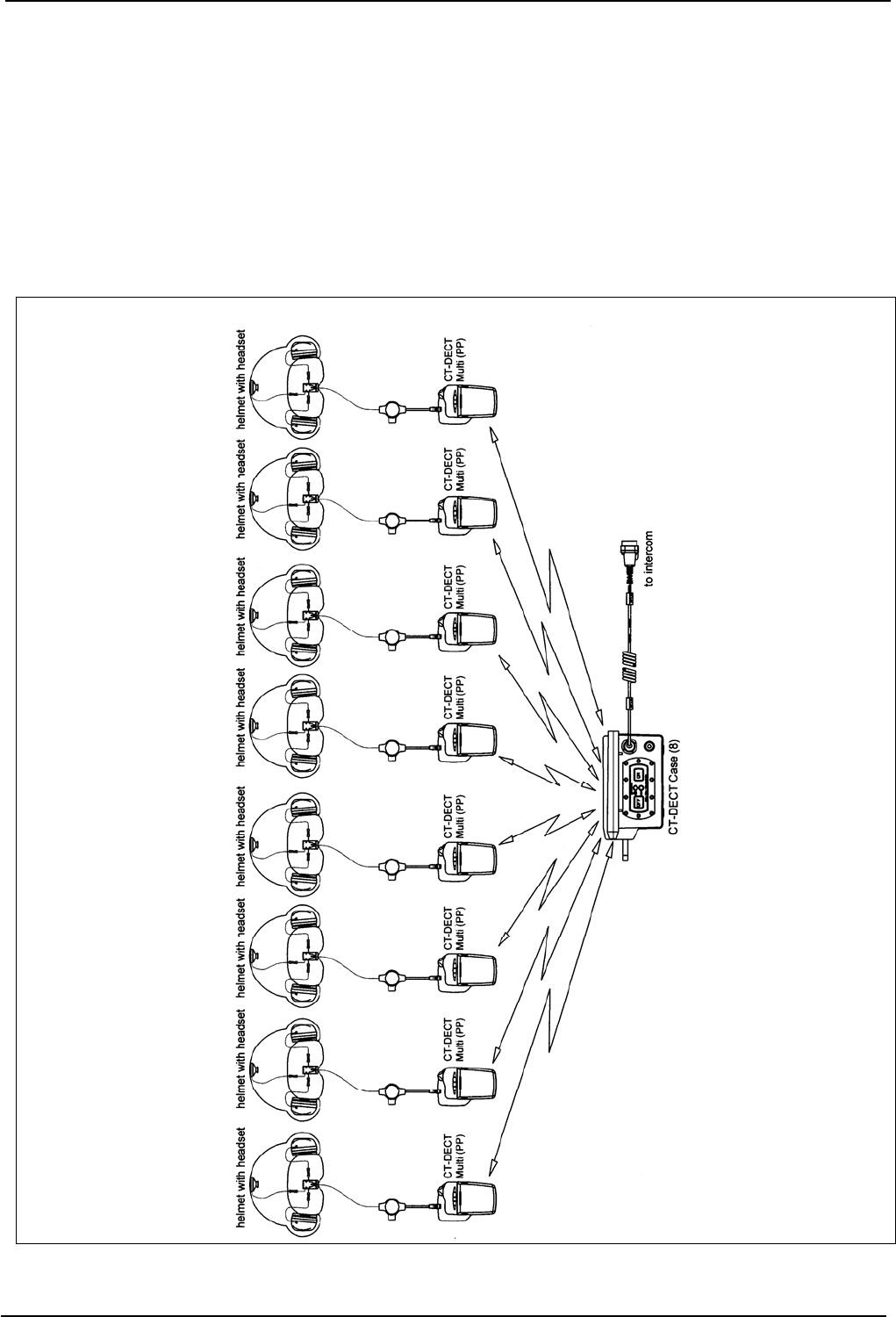
The CT-DECT Case (8) is suitable for duplex communication over short distances between maximum 8
»mobile« users and the aircraft crew. Mobile users are using CT-DECT headsets (PP) or other head-
sets in conjunction with the CT-DECT Multi (PP). Communication between »mobile« users is wireless.
The CT-DECT Case (8) is the central unit of the DECT system and includes the CT-DECT interface
base (FP). The »mobile« users are subscribed to the CT-DECT Case with their devices (PP). With a
special adapter cable it is possible to connect the CT-DECT Case (8) to the intercom system of the air-
craft. The working range between the CT-DECT Case (8) and the devices (PP) subscribed to it de-
pends on the local conditions. A high degree of tapping and interference protection is assured.
Figure 1 System overview / Example

7
2.1 Technical data
Unit is equipped with
- Interface for up to maximum 8 users
- Battery compartment for 3 AA-batteries
- Acoustic multilevel warning „Low-Battery“ in the subscribed headset
- Optical multilevel warning „Low-Battery“
- ON/OFF switch with optical status indication
- 2 buttons for subscription on the Interface
- 1 buttons for subscription outside at the case
- 9-pole connection socket
- Hinged handle
- 2 locking
Dimensions: 210 x 202 (grasp in hinged position) x 90 mm
Technical Data
USA
Frequency band 1920 – 1930 MHz
Mode of Transmission TDMA 24 Slots per frame
Channel spacing 1,728 MHz
Automatic channel selection 5 channels
Transmission range ≥200m (obstacle-free area)
≥75m (dependent on the local conditions)
Power supply rechargeable batteries NiMH or
AA-batteries
Operating time approx. 8 hours (by 23°C) on use of the
provided rechargeable batteries
to the CT-DECT Case (8) belong likewise:
Flag with label "Remove before Flight"
Signal color red with white letter
Dimensions: 500 mm x 75 mm
Material: Polyester 700g/m²
Attachment parts
Consisting of
- 2 x shackles
Material: FE/X (#4401)
- 2 x hooks
Material: Steel powder-coated RAL 9005 matt-finished
8
2.2 Technical description
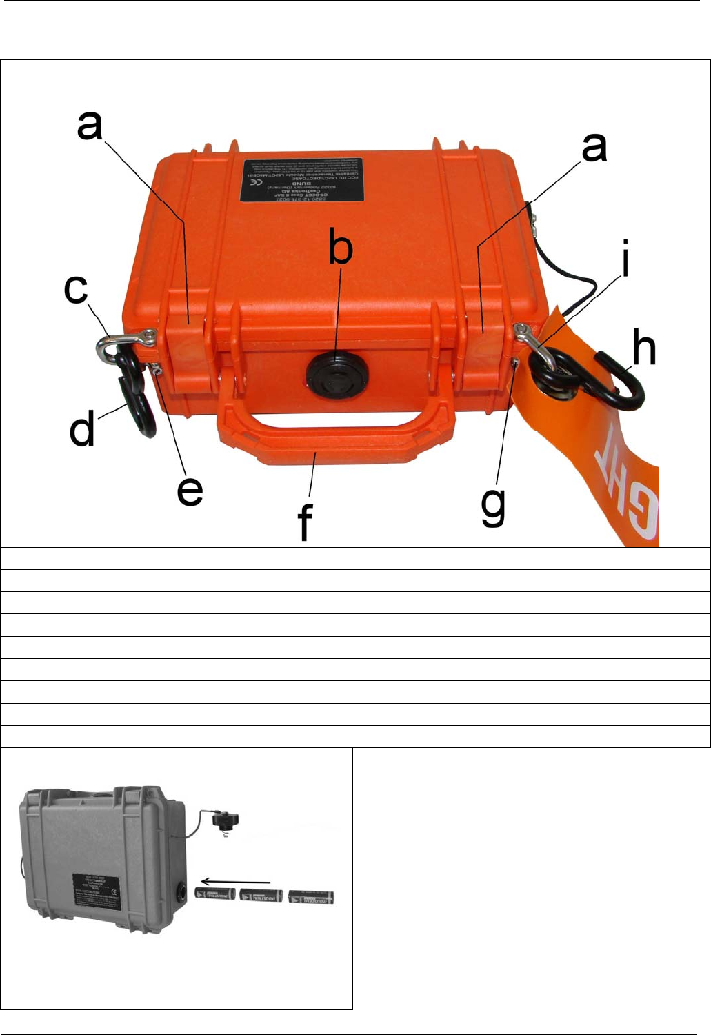
Figure 2
a Latch to unlock and lock the case
b Automatic purge valve for equalization after changes in atmospheric pressure
c Shackle to hang up the hook (item »d«)
d Hook to hang up the CT-DECT Case (8) at the aircraft
e Screw for fastening the shackle (item »c«)
f Hinged handle
g Screw for fastening the shackle (item »i«)
h Hook to hang up the CT-DECT Case (8) at the aircraft
i Shackle to hang up the hook (item »h«) and the strap »REMOVE BEFORE FLIGHT«
Figure 3, Battery compartment
The battery compartment is located on the RH side
of the case. The battery compartment is locked up
with a screw cap, which itself is secured to the
case with a retaining band. The rechargeable bat-
teries are inserted into the compartment with the
positive pole facing forward (see arrow).
9
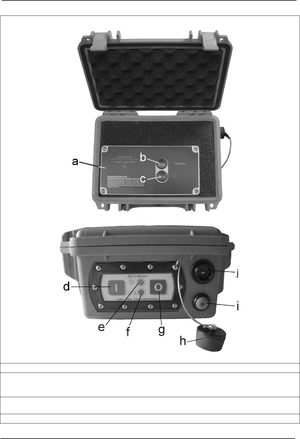
Figure 4
a Interface CT-DECT Case (8)
b Push button »1/extern« for subscription of max. four CT-DECT Multi (Man-Pac) to the CT-DECT
Interface. The push button »1/extern« has equal functional rights as the external button (item »i«)
on the outside of the case
c Push button »2« for subscription of max. four CT-DECT Multi (Man-Pac) to the CT-DECT Inter-
face.
d Green push button ON to switch on the device

10
e Control lamp illuminates if the device is switched on
f Control lamp, batteries
green illuminates constant UB > 3,6V
green flashes 3,4V < UB ≤ 3,6V
red flashes UB ≤ 3,4V, approx. 30 minutes operating time
LED OFF UB ≤ 2,7V, no function
g Red push button OFF to switch off the device
h Cap for the 9-pin plug (item »h«)
I External push button for subscription of max. four CT-DECT Multi (Man-Pac) to the CT-DECT Case
(8). These four CT-DECT Multi (Man-Pac) can be subscribed by the external push button to the
CT-DECT Case (8) without opening the case.
The push button has equal functional rights as the internal button »1/extern« (item »b«) in the case
j 9-pole plug for connection the CT-DECT Case (8) to a aircraft interface via an aircraft specific
adapter cable
Î PLEASE NOTE:
When using the CT-DECT Case (8) via the aircraft-specific CT adapter cable, without connection
to the aircraft’s intercom system, the sealing cap should always be plugged onto the unused 9-
pole connector (item »j«) to protect the jack against humidity and dirt.

11
3. Operation
3.1 First commissioning
At the beginning new NiMH rechargeable batteries do not deliver maximum power. Maximum power is
achieved only after a few recharging cycles.
Before charging rechargeable NiMH batteries, they must be completely discharged about once a
month. If this procedure is not followed, rechargeable batteries will not deliver anymore full power after
only a short time. Each communication device uses 3 rechargeable batteries. If one or more recharge-
able batteries are not fully charged, this will affect the reliability of the entire system. As it is not possible
to determine which one of the rechargeable batteries is in poor condition, the complete set must be
replaced. Proper care and handling helps controlling the number of rechargeable batteries in use.
The life of rechargeable batteries may vary as a result of daily recharging, natural ageing, and varying
operating conditions.
3.1.1 Recharging the NiMH rechargeable batteries
3.1.1.1 General
The rechargeable NiMH batteries in the device should only be charged with the charger supplied with
the system. Otherwise the rechargeable batteries may be damaged. The charger is neither watertight
nor dust-proof. Protect it against water, rain and dirt. The charger may only be used in rooms with nor-
mal relative air humidity and temperature. Do not cover up the charger.
Warning
z Never use battery chargers to charge non-rechargeable batteries.
Never open rechargeable batteries or throw them into fire. Do not open charger.
The repair is permitted only by the manufacturer.
z Never charge a rechargeable battery in areas with an explosion risk – an explosion may re-
sult. Charge rechargeable batteries only inside buildings or similar environments where no
dangerous concentrations of volatile vapors are present.
The three NiMH batteries are in the battery compartment of the CT-DECT Case (8). For charging they
have to be removed from the battery compartment.
a. Switch off the device CT-DECT Case (8).
b. Remove the cover from the battery compartment (Fig. 3).
c. Take the three NiMH batteries out the battery compartment. Charge the rechargeable batteries with
the charger.
e. After charging: When inserting the charged NiMH batteries notice the polarity. Close the battery
compartment.

12
3.1.2 On-air subscription of the CT-DECT device (PP) to the CT-DECT Case (8) (FP)
Î NOTES
● The on-air subscription is not part of the normal commissioning and operating procedure
for the system. It must be performed again only in the case a CT-DECT device (PP) that isn't
subscribed to the CT-DECT Case (8) has to be used in conjunction with the CT-DECT Case
(8).
● CT-DECT devices (PP) can be subscribed to only one CT-DECT Case (8), never to two or
more CT-DECT Case (8) units simultaneously.
Î NOTES
z Two ore more CT-DECT devices (PP) can never be simultaneously subscribed to the CT-
DECT Case (8), they must always be subscribed one after the other.
With two ore more CT-DECT devices (PP) it is recommendable to subscribe all devices one
after the other to the CT-DECT Case (8), because a device can be deleted (see 3.1.2.1 »Princi-
ple of subscription«).
z Comply with the instruction step sequence.
z After subscription all new subscribed devices have to be switched off again.
The on-air subscription procedure is performed on the CT-DECT Case (8) and the CT-DECT devices
(PP) manually by means of operating elements. The CT-DECT Case (8) is the unit to which the maxi-
mum eight (8) CT-DECT devices (PP) of a system need to be subscribed to.
The CT-DECT Case (8) is equipped with two transceiver modules, the both subscription buttons (Fig.
3/b,c,i) and is able to control max. eight CT-DECT devices (PP). In each case max. four CT-DECT de-
vices (PP) are allocated to one transceiver module. Every four CT-DECT devices (PP) are assigned in
groups to the subscription buttons (figure 4/b, c). The function of the outside button (figure 4/i) is identi-
cal to that of the subscription button shown in figure 4/b.
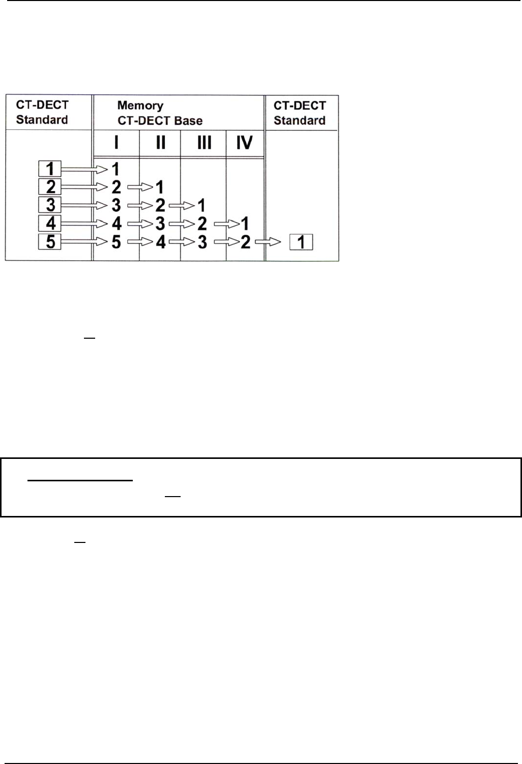
3.1.2.1 Principle of subscription
Four CT-DECT devices (PP) can be assigned to each transceiver module in the CT-DECT Case (8).
The four CT-DECT devices (PP) assigned to a transceiver module should always be subscribed in
groups, but of course individually one by one.
Should a fifth CT-DECT device (PP) be subscribed to one and the same transceiver module, then the
CT-DECT device (PP) subscribed first would be deleted from the transceiver module’s memory (see
example in figure 5).
Î PLEASE NOTE:
The subscription procedure for a group of maximum four CT-DECT units (PP) which are sub-
scribed with the help of button “2” (figure 4/c) differs from the procedure when subscribing CT-
DECT devices (PP) with the “1/external” buttons (figure 4/b, i). The subscription procedure can
be performed while communicating without any need to switch off and open the CT-DECT Case
(8).
The procedure, applicable for subscribing maximum four CT-DECT devices (PP) with button “2”
(figure 4/c) is described in chapter 3.1.2.2 and for subscribing the other maximum four CT-DECT
devices (PP) with the help of buttons “1/external” (figure 4/b, i) in chapter 3.1.2.3.
13
A CT-DECT device (PP) which has been deleted from the CT-DECT Case (8) memory cannot commu-
nicate anymore with the DECT system and needs to be re-subscribed to the base unit following the
subscription instructions.
Fig. 5 Principle of subscription (example)
Timeout
If a subscription is not successfully completed within maximum 2 minutes since starting the process, a
»timeout« occurs. The timeout is signalized by a sequence of 4 short low tones in the headset of the
CT-DECT device (PP), repeating in 4-second intervals.
After a timeout all CT-DECT devices (PP) subscribed to a transceiver module need to be subscribed
anew to the CT-DECT Case (8). In the event of only one CT-DECT unit (PP) the subscription of this
single CT-DECT unit (PP) has to be repeated.
3.1.2.2 Example of subscribing a CT-DECT device (PP) with subscription button 2 (figure
4/c)
The following describes the procedure for subscribing a CT-DECT device (PP) to a CT-DECT Case (8)
with the subscription button »2« (figure 4/c). The subscription of the remaining three CT-DECT devices
(PP) (maximum four units) with button »2« is done likewise.
Î PLEASE NOTE:
After successful subscription, all CT-DECT devices (PP) and the CT-DECT Case (8) must be
switched off again before putting the DECT system into operation.
a. Make sure all CT-DECT devices are switched off.
b. Unscrew the two screws (figure 2/e, g) on the CT-DECT Case (8) and remove the two shackles (fig-
ure 2/c, i) from the case. Unlock the two latches (figure 2/a) and open the case.
c. Leave the CT-DECT unit (PP) still switched off.
d. Press the subscription button »2« (figura 4/c) inside the CT-DECT Case (8) and keep it depressed.
Switch on the CT-DECT Case (8) with the green push-button (figure 4/d) while the subscription but-
ton is depressed and keep it depressed for at least another 5 seconds after switch-on. Then release
the subscription button and continue directly with step »e« in order to avoid a »timeout«.
e. Press the subscription button on the CT-DECT device (PP) and keep it depressed. Switch the CT-
DECT device (PP) on while depressing the subscription button and keep it depressed for at least
another 5 seconds since switch-on until you hear a descending 5-tone sequence in your headset.
Then release the button.
The subscription process has been initiated and you hear in the headset of the CT-DECT unit (PP)
about every 2 seconds an intermittent high beep. An ascending 5-tone sequence, which repeats in

14
4-second intervals, finally informs you that the subscription process has been completed success-
fully.
If, after maximum 2 minutes, the subscription process was not successful, this is signalized by a se-
quence of 4 short low tones, repeating in 4-second intervals.
In that case, switch off again the CT-DECT Case (8) and the CT-DECT device (PP) and repeat the
entire subscription process.
f. After successful completion of the subscription process, switch off again the CT-DECT de-
vice (PP) and the CT-DECT Case (8) before commissioning the units (chapter 3.2.6).
Î PLEASE NOTE:
The subscription procedure described in chapter 3.1.2.3 while the communication system is
operating applies only to the four CT-DECT devices (PP), which are being subscribed via the
inside subscription button »1/external« (figure 4/b) or the one on outside of the case (figure 4/i).
3.1.2.3 Example of subscribing a CT-DECT device (PP) during operation
When subscribing maximum four CT-DECT devices (PP) to the CT-DECT Case (8) using the subscrip-
tion button “1/external” (figure 4/b, i) the CT-DECT Case (8) must not necessarily be in switched-off
condition. Subscription can be accomplished while the CT-DECT Case (8) is operating. This makes it
possible that the maximum four users, who already subscribed their CT-DECT devices (PP) with the
help of the subscription button 2, can continue to operate while additional CT-DECT devices (PP) are
being subscribed to the CT-DECT Case (8) via the “1/external” subscription buttons (figure 4 b/i). The
subscription process can be aborted at any time by simply pressing the external subscription button
(figure 4/i) during the subscription process.
Both subscription buttons (figure 4/b, i) have equality of access. For a fast subscription when in opera-
tion, normally the external subscription button (figure 4/i) located on the outside of the case is used, so
that the case does not need to be opened.
The following example describes the subscription process using the external subscription button (figure
4/i) located on the outside of the CT-DECT Case (8). Other CT-DECT devices (PP) (max. four) are
subscribed likewise with this button (figure 4/i).
a. Firstly, leave the CT-DECT device (PP) switched-off.
b. Press the external subscription button (figure 4/i) of the switched-on CT-DECT Case (8) and keep it
depressed for at least 5 seconds. Then release it and continue directly with step »c« in order to
avoid a »timeout« (see chapter 3.1.2.1).
The LED of the subscription button (figure 4/i) lights up. If a »timeout« occurs, the LED starts to
flash.
c. Press the subscription button of the CT-DECT device (PP) and keep it depressed. Switch the CT-
DECT device (PP) on while depressing the subscription button and keep it depressed for at least
another 5 seconds since switch-on until you hear a descending 5-tone sequence in your headset.
Then release the button.
The subscription process is initiated and you hear in the headset of the CT-DECT device (PP) about
every 2 seconds an intermittent high beep. An ascending 5-tone sequence, which repeats in 4-
second intervals, finally informs you that the subscription process has been completed successfully.
After a successful subscription the LED of the subscription button (figure 4/i) on the CT-DECT device
(PP) goes out.
If, after maximum 2 minutes, the subscription process was not successful, this is signalized by a se-
quence of 4 short low tones, repeating in 4-second intervals.
If the subscription process is not completed successfully, the LED of the subscription button (figure
4/i) starts flashing. In that case switch the CT-DECT device (PP) off again and repeat the entire proc-
ess.
d. After successful completion of the subscription process, switch the CT-DECT device (PP)
again off before commissioning the unit; the CT-DECT Case (8) must not be switched off.
15
3.2 Commissioning
3.2.1 Connecting the CT-DECT Case (8) to the aircraft
The batteries of the CT-DECT Case (8) must be fully charged.
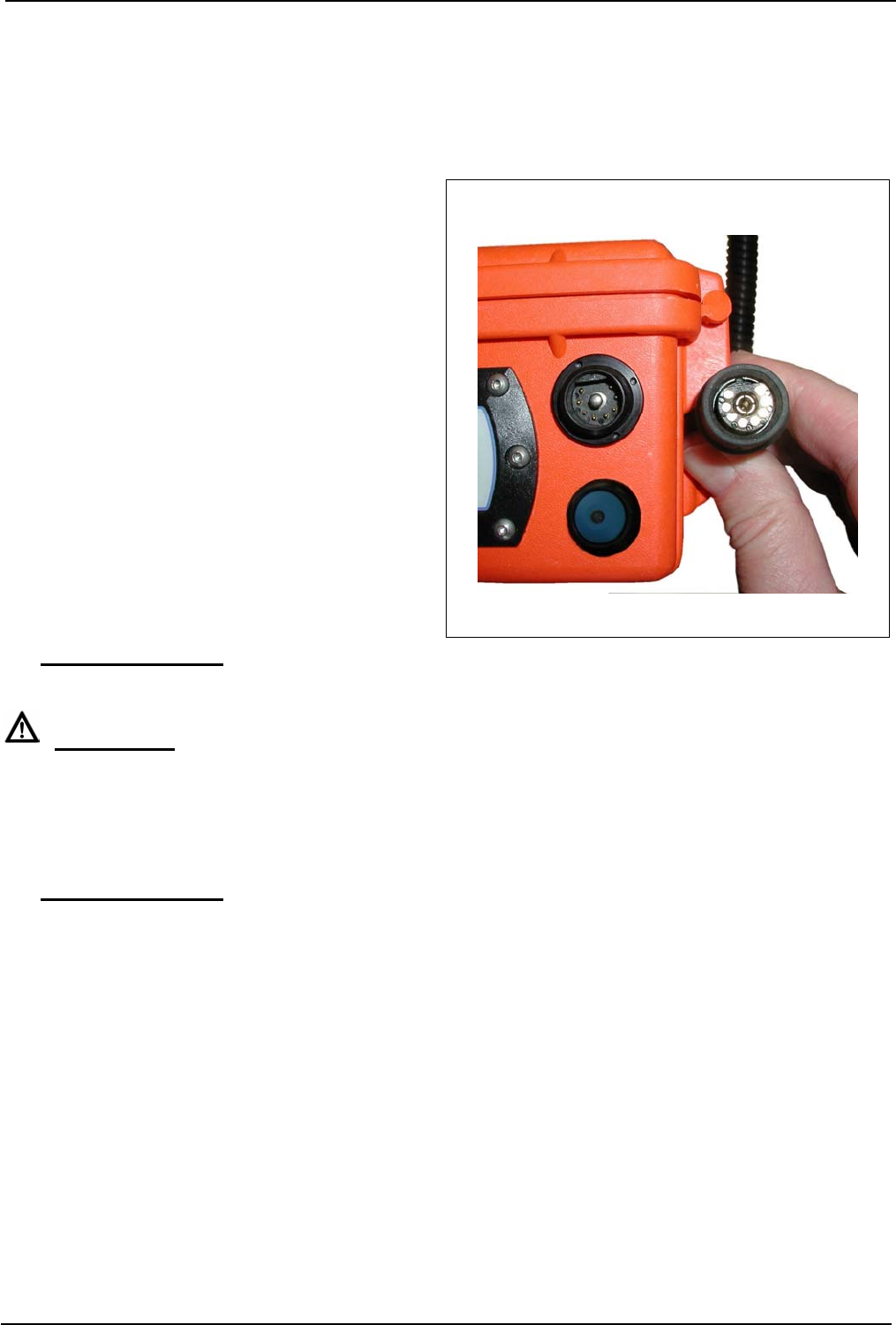
a. Establishing the 9-pin plug-in connection at
the CT-DECT Case (8)
The 9-pole jack of the CT-adapter cable (figure
6) has a distortion protection.
Hold the case down with one hand. Put the jack
onto the 9-pin connector of the CT-DECT Case
(8) and turn it until it slides a little into the con-
nector. With it, the correct plug-in position has
been found.
Now push the jack into the connector until it
engages audibly.
To disconnect the plug-in connection, hold the
case down with one hand and pull the jack out
of the connector.
b Connect the CT-DECT Case (8) with the CT
adapter cable to the intercom connector of the
aircraft.
Figure 6, 9-pin plug-in connection at the
CT-DECT Case (8)
Î PLEASE NOTE:
During outdoor operations keep the CT-DECT Case (8) always closed!
CAUTION!
The CT-DECT Case (8) may be connected to an aircraft only with the flag “Remove before flight”
attached.
3.2.2 Switching-on of CT-DECT Case (8) and CT-DECT device (PP)
Switch-on, establishing connection, adjusting the volume
Î PLEASE NOTE:
Applies to CT-DECT devices (PP) which are subscribed to a CT-DECT Case (8)
a. First switch on the CT-DECT Case (8) using the green push-button (figure 4/d). The CT-DECT Case
(8) starts now an initialization process during which it may not be switched off. After initialization the
pilot lamp (figure 4/e) lights up. If the pilot lamp (figure 4/f) flashes, the voltage of the batteries in the
CT-DECT Case (8) is low and needs to be recharged.
b. Switch on the CT-DECT devices (PP) you want to communicate with. After switch-on you will hear a
high beep in the headset. After this, synchronization, i.e. the search process, starts between the CT-
DECT Case (8) and the CT-DECT devices (PP), the duration of which may vary. While this process
is under way, a high-low tone sequence will be heard every second in the headsets, indicating, that
the CT-DECT devices (PP) are seeking their CT-DECT Case (8).
After successful synchronization - i.e. a CT-DECT device (PP) found its CT-DECT Case (8) - the high-
low tone sequence falls silent and a high double beep is heard in the headset. CT-DECT Case (8) and
CT-DECT device (PP) establish now automatically the connection between one another. As soon as
the connection is established a final high beep will be heard in the headset. This indicates that the units
are ready for duplex communication within the working range between CT-DECT device (PP) and base
unit.

16
3.3 Controls
Duplex communication between »mobile« users
After switch-on of the CT-DECT Case (8) and the CT-DECT devices (PP) and successfully completed
automatic establishment of connection (see chapter 3.2.6) the units are ready for duplex communica-
tion within the working range between CT-DECT devices (PP) and CT-DECT Case (8). Microphones
and headsets are permanently switched on. Each user can speak in its headset microphone and hear
in the earpiece of his headset the conversation of the other users. Adjust the communication volume
with the volume control for your headset earpieces. Never adjust the volume higher than necessary for
clear and proper communication.
Communication between »mobile« users and the aircraft intercom system
With the help of the PTT button on the headset, communication between »mobile« users and the crew
of the aircraft is possible, while the PTT button is pressed.
Pressing the »COM ON/OFF« buttons on the CT-DECT devices (PP) once establishes communication
between »mobile« users and the crew aboard the aircraft; pressing a second time cuts the communica-
tion off.
If the communication between »mobile« users and the aircraft crew is OFF, a high double beep sounds
in the headset after pressing the buttons. Now, communication is switched on.
If the communication between »mobile« users and the aircraft crew is ON, a low double beep sounds in
the headset after pressing the buttons. Now communication is cut off.
Only the »mobile« user establishing the intercom connection is connected with the crew of the aircraft
and only he can terminate the connection.

17
3.4 Operating under special climatic conditions
The system is tested and approved for use within a working temperature range from -30°C up to +55°C.
Exceptions apply to batteries and charging devices.
Rechargeable batteries
Very low or very high temperatures affect the life of rechargeable batteries.
Rechargeable batteries may only be used in the temperature range from 0°C to +50°C. At temperatures
below 0°C we recommend the use of alkaline batteries.
As CT-DECT devices (PP) are used close to the body, temperatures below 0°C are rarely seen.
However, the CT-DECT Case stands (is suspended) in open air; therefore we recommend at very low
temperatures the use alkaline batteries instead of rechargeable ones.
Mobile (plug-type) battery charger
Working temperature range: 0°C – 25°

18
4. Maintenance and proper care
4.1 Visual inspection
Inspect the system and particularly cables and connector assemblies regularly for signs of cracks, fis-
sures, and deterioration.
4.2 Cleaning
After every use the entire system should be cleaned.
ATTENTION!
Pay attention that no humidity could penetrate into the device during cleaning.
Do not use solvents (e.g. benzene, alcohol, etc.) for cleaning!
Remove loose dust with a soft brush. Clean the outside of components, if necessary, with an appropri-
ate clean cloth, only lightly moistened with clear water, and then rub it down thoroughly. If heavily
soiled, a few drops of rinsing agent may be added. Clean the connector pins with a commercial clean-
ing agent.
4.3 Faults, causes, corrective actions
Fault Cause Corrective action
CT-DECT Case (8), no LED
lights up after switch-on
Rechargeable batteries are
completely run down or defec-
tive
Recharge or replace recharge-
able batteries
CT-DECT Case (8), life of re-
chargeable batteries is too short
Rechargeable batteries are de-
fective
Replace rechargeable batteries
After switching the system on,
automatic establishment of con-
nection is not completed suc-
cessfully
CT-DECT device (PP) is not
subscribed to the CT-DECT
Case (8)
Perform subscription procedure
4.4 Storage
The equipment can be stored at temperatures from -40°C up to +80°C. Exceptions apply to recharge-
able batteries and battery chargers.
Rechargeable batteries
Store rechargeable batteries at: -20°C...50°C for 30 days maximum
-20°C...40°C for 3 months maximum
-20°C...30°C for 1 year maximum
Mobile (plug-type) battery charger
Storage temperature range: -25°C – +70°C

19
4.5 Transport and shipping
Use only the original packing for any transport purposes.
Transport only clean and dry systems. Prior to any transport remove all rechargeable batteries from all
units.
5. Replacements to be made by the user
5.1 Replacing components
5.1.1 CT-DECT Case (8)
5.1.1.1 Replacing the warning flag
Unscrew the screw (figure 3/g) for removing the shackle. Remove the defective “Remove before Flight”
flag and replace it by a new one. Fasten the screw again.
5.1.1.2 Replacing the cap for the 9-pole jack
The cap is delivered complete with steel cable and eye. Remove the key ring with steel cable from the
case. Fasten the new cap with steel cable and key ring to the case.
5.1.1.3 Replacing the cap for the battery compartment
The cap is delivered complete with steel cable and eye. Remove the key ring with steel cable from the
case. Fasten the new cap with steel cable and key ring to the case.
Germany and
International Sales
CeoTronics AG
Adam-Opel-Str. 6
63322 Rödermark
Tel. +49 6074 8751-0
Fax +49 6074 8751-676
E-Mail sales@ceotronics.com
USA/Canada/Mexico
CeoTronics, Inc.
300 Southport Circle, Suite 103
Virginia Beach, Virginia 23452
Tel. +1 757 549-6220
Fax +1 757 549-6240
E-Mail sales@ceotronicsusa.com
France
CeoTronics Sarl
Bât. Delta T
Z.A. du Tuboeuf
Allée des Pleus
77257 Brie Comte Robert Cédex
Tel. +33 1 60183300
Fax +33 1 60286060
E-Mail ventes@ceotronics.fr
Spain
CeoTronics S.L.
C/Ciudad de Frias 7 y 9
Nave 19
28021 Madrid
Tel. +34 91 4608250 51
Fax +34 91 4603193
E-Mail ventas@ceotronics.es
Switzerland
CeoTronics AG
Grundstr. 16
6343 Rotkreuz
Tel. +41 41 7905838
Fax +41 41 7905839
E-Mail info@ceotronics.ch
Poland
CeoTronics Sp. z o.o.
ul. Słonecza 15
91-491 Łódź (Polska)
Tel. +48 42 6553311
Fax +48 42 6552288
E-Mail biuro@ceotronics.pl
Germany and
International Sales
CT-Video GmbH
Gewerbegebiet Rothenschirmbach 9
06295 Lutherstadt Eisleben
Tel. +49 34776 6149-0
Fax +49 34776 6149-11
E-Mail ctv.info@ceotronics.com
EIGENE/CT-DECT Case/dok1200-gb.doc/00/1007 y DOK 1200 Änderungen vorbehalten
Copyright © 10/2007 CeoTronics AG, 63322 Rödermark, Deutschland, Internet www.ceotronics.com