Ceragon Networks CRN-FA1500-24 Point to Point Radio User Manual 01intro
Ceragon Networks Ltd. Point to Point Radio 01intro
Contents
Users Manual Part 9

Installation Instructions
Integrated Radio Interface
2.5ft Antennas
AN-0029-0, AN-0027-0, AN-0016-0
CERAGON, Sept-2000
CERAGON Ltd.
24 Raul Valenberg Street, Tel-Aviv, 69710,
Israel Tel: +972-3-6455733 Fax: +972-3-
6455499 Home Page: www.ceragon.com
Installation Instructions
Giganet Antenna Mount from...
1
2
21
20
19
13
13
15
15
13
13
6
AN-0029-0, AN-0026-0, AN-0027-0, AN-0016-0
21
19
20
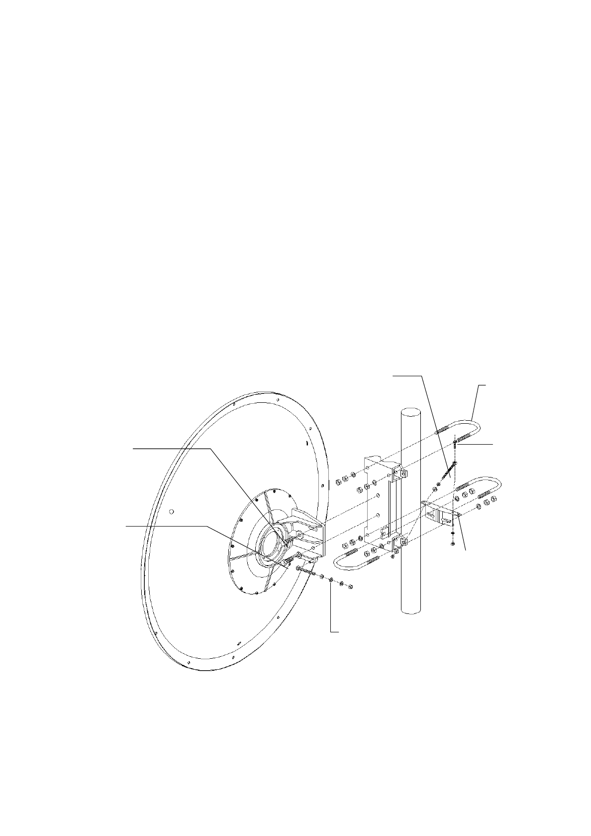
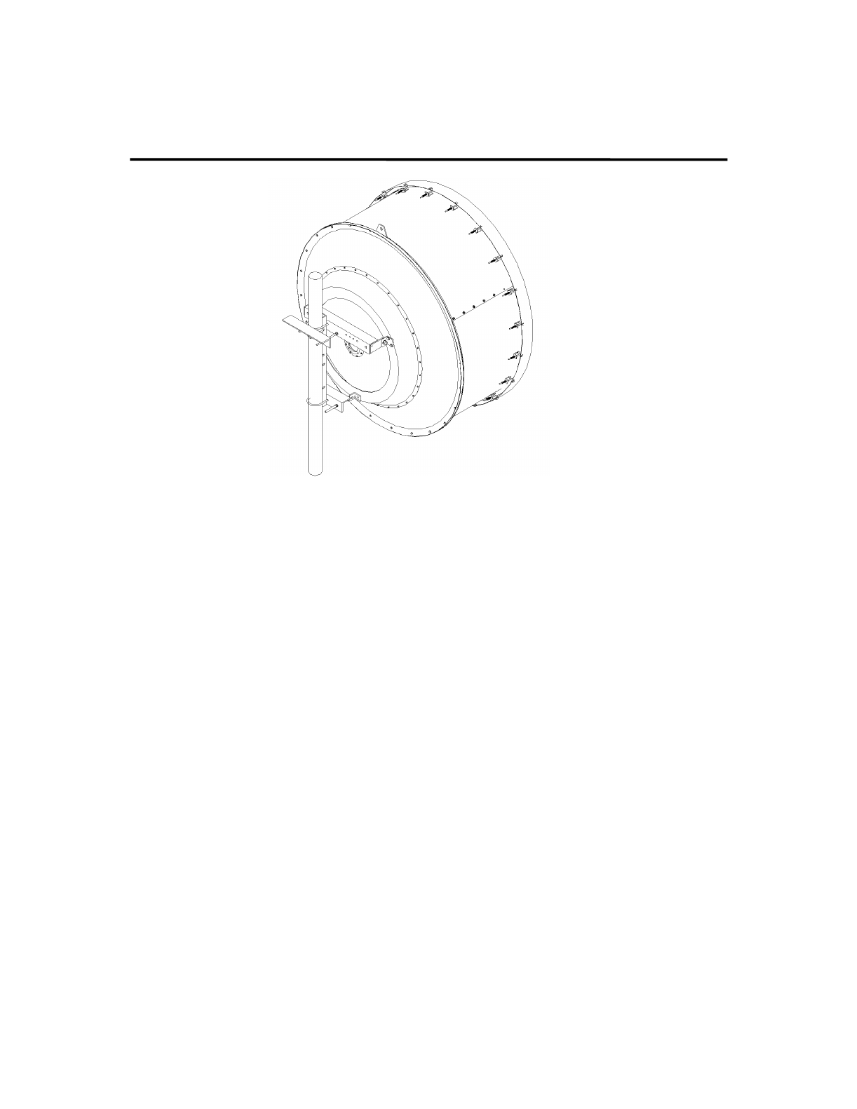
Description
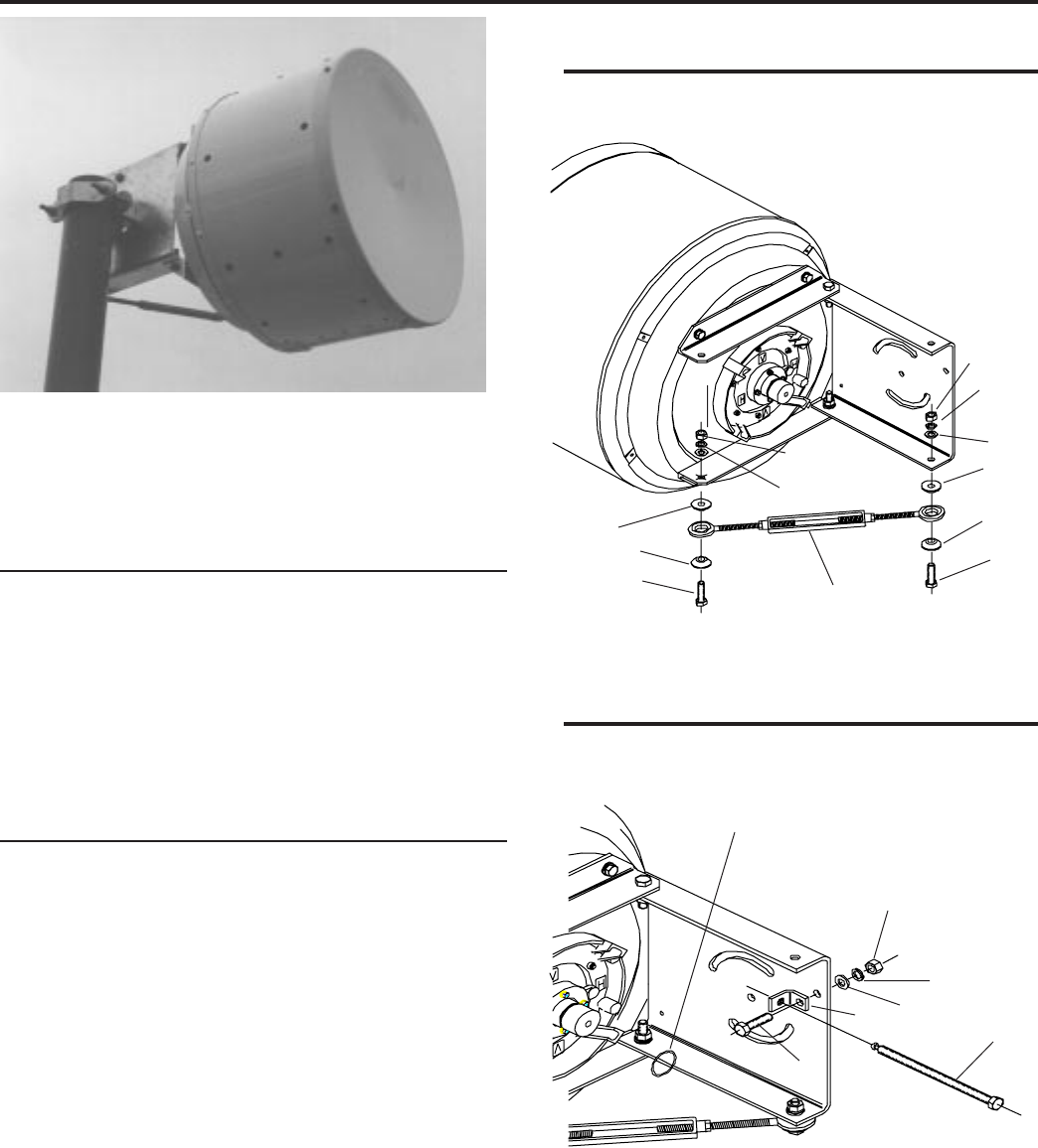
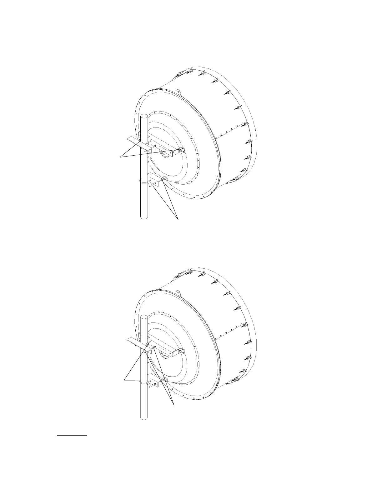
This antenna consists of a 0.8-meter (2.5ft) shielded reflector,
radome, feed, and offset tower mount. The mount is designed
to attach the antenna to a vertical tower pipe of diameter 64
to 115 mm (2.5 to 4.5"). The mount also provides adjustment
ranges of ±50° elevation and ±180° (+15, -7.5° fine) azimuth.
Notice
The installation, maintenance, or removal of antenna systems
requires qualified, experienced personnel. Manufacturer's
installation instructions have been written for such personnel.
qualified personnel to verify proper installation, maintenance,
and condition of equipment.
Manufacturer disclaims any liability or responsibility for the
results of improper or unsafe installation practices.
21
19
20
9
10
15
Apply silicone grease (23)
to O-ring (22) prior to fitting
Ceragon systems should be inspected once a year by
3 5
4
21
20
19
20
19
8
14
7
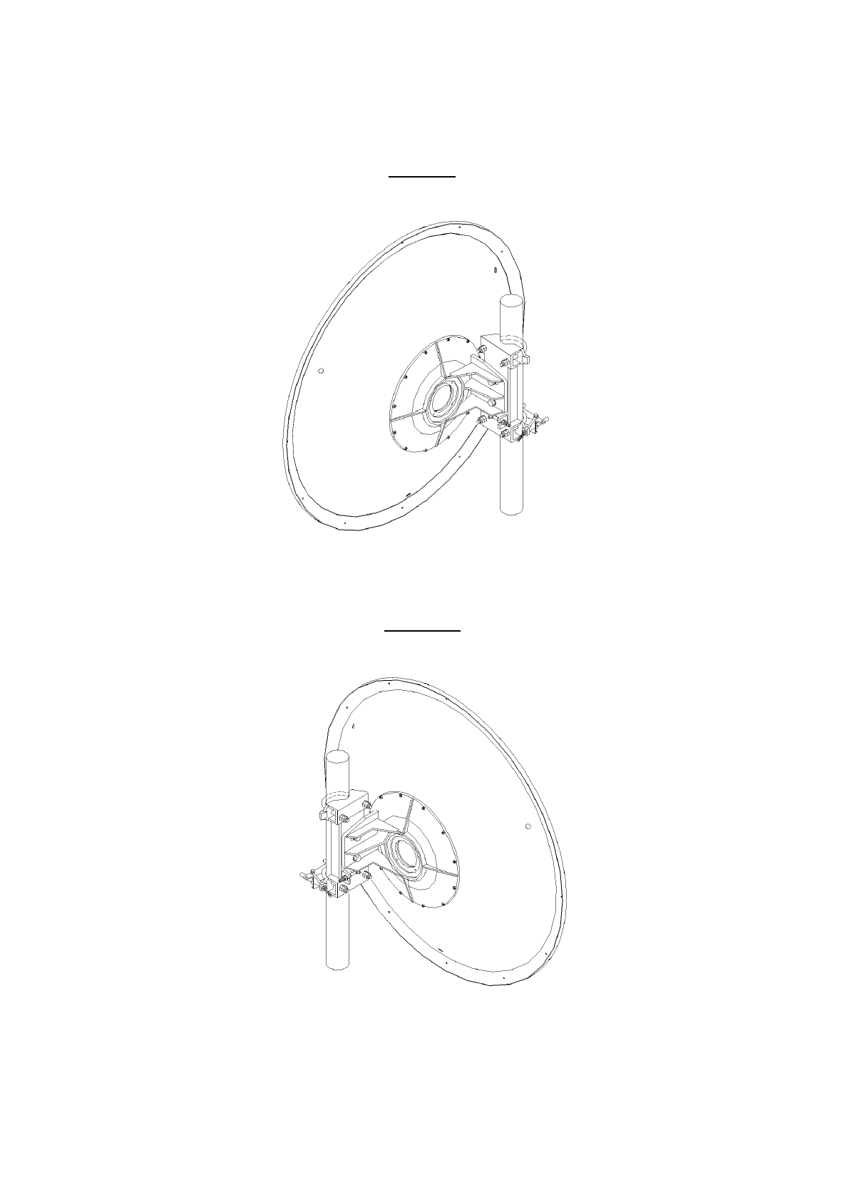
14
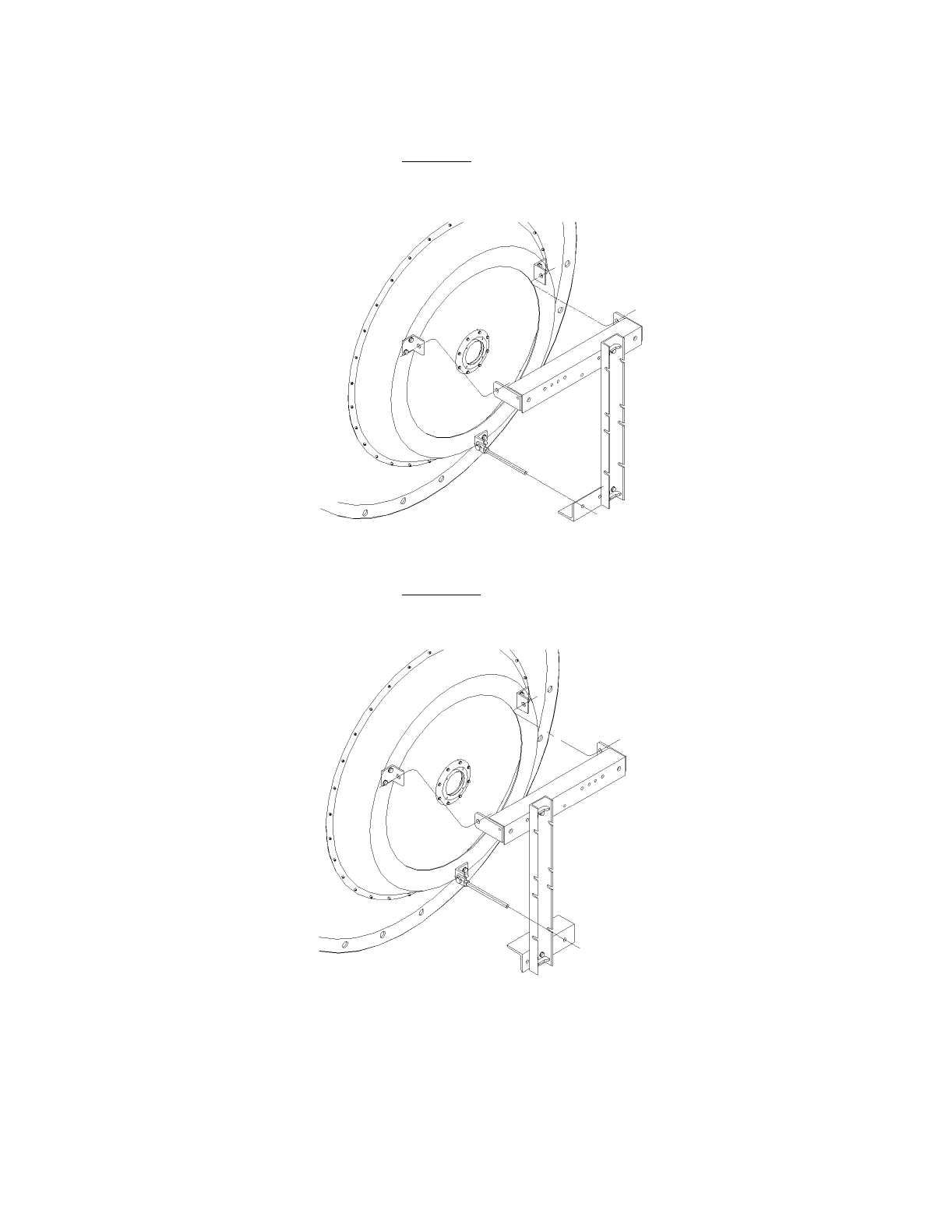
Antenna
offset left
Antenna
offset right
0°
Elevation Adjustment Ranges
+15° to -50° +15° to +50°
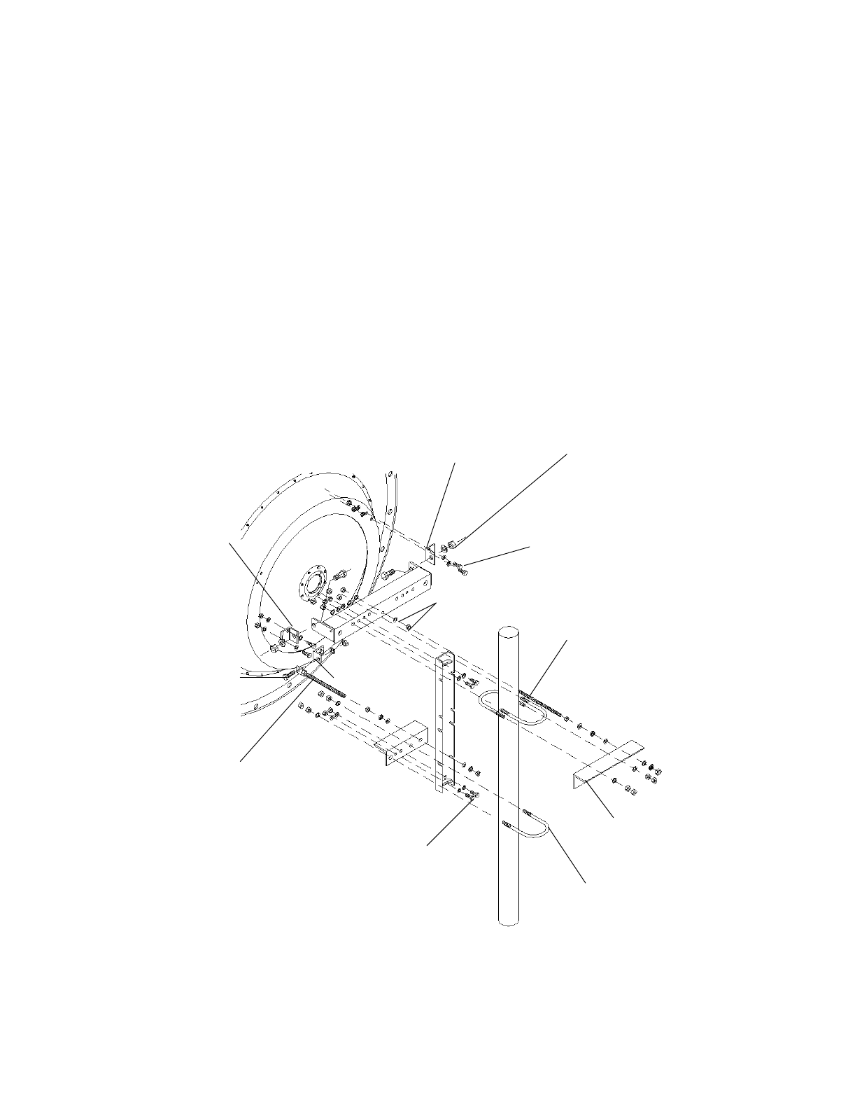
18
16
20
19
17 16
17
21 20 19 18
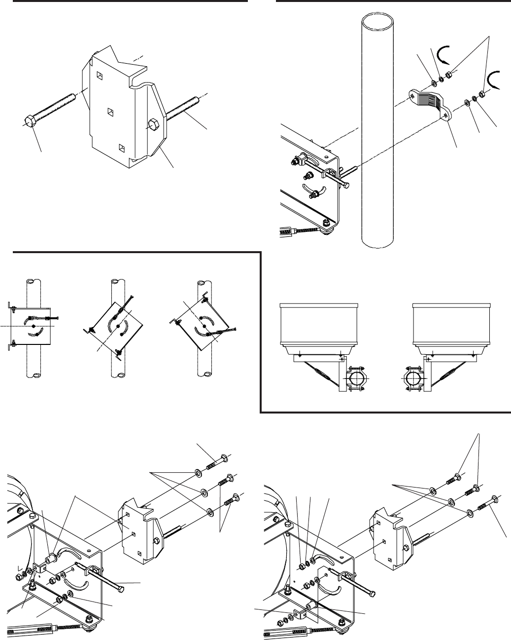
Mount Arrangement for Elevation of +15° to +50°Mount Arrangement for Elevation of +15° to -50°
Apply Grease
to these
Surfaces
Apply Grease
to this
Component
12
21
11 12
11
50N/m
50N/m
6
7
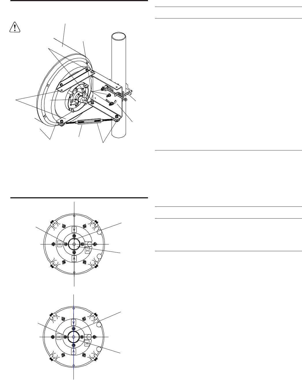
polarization
indicator
notch
Rotate feed
hub (4) to
adjust
polarization
Table 2. Fastener Torque Specifications
Fastener Torque value in N·m (lb·ft ) for each fastener size
Size M5 M6 M8 M10 M12 M16
Stainless 4.5 7.7 18.7 39.2 65.1 161
steel (3.3) (5.7) (13.8) (28.9) (48) (118.7)
Galvanized 2.7 4.5 11.1 22 38 95
steel (2) (3.3) (8.1) (16.2) (28) (70.1)
Remove 4 off M6
bolts to adjust
polarization
Vertically Polarized Application
Rotate feed
hub (4) to
adjust
polarization
Remove 4 off M6
bolts to adjust
polarization
Horizontally Polarized Application
polarization
indicator
notch
Loosen for
adjusting
azimuth
Loosen for
adjusting
azimuth
Adjust
azimuth
turnbuckle
(6)
Caution:
1
2
3
Loosen for
adjusting
elevation
Loosen for adjusting
azimuth to avoid
reflector damage
4Adjust
elevation
Table 1. Antenna Parts List
Item Description Part no. Qty
1 Reflector/shield assembly 113502 1*
2 Mount plate 108992 1*
3 Mount angle bracket 108984 2*
4 Feed assembly # 1*
5 Radome # 1*
6 Azimuth adjustment turnbuckle 224403-2 1
7 Mount pivot plate 109103 1
8 Half clamp (cap) 109036 1
9 Elevation adjustment bolt 109105 1
10 Upper bracket 108995 1
11 Slotted bracket 108994 1
12 Spacer 109104 1
13 Bevel washer 224322-1 1*+3
14 M12 x 110 hex head bolt, gs 100535-132 2
15 M12 x 45 hex head bolt, gs 100535-42 1*+2
16 M12 x 80 carriage bolt, gs 204026-4 1
17 M12 x 45 carriage bolt, gs 204026-2 2
18 M16 flat washer, gs 100521-51 3
19 M12 flat washer, gs 100521-45 8
20 M12 lock washer, gs 100522-45 8
21 M12 hex nut, gs 100526-45 1*+7
22 O-Ring 106837-3 1
23 Silicone Grease (tube) 12225 1
* Part of antenna sub-assembly
# Frequency Dependant
gs Galvanised Steel

Installation Instructions
For 4ft (1.2 m) & 6 ft (1.8 m) Integrated Antennas
AN-0033-0, AN-0030, AN-0015-0
Tel: +972-3-6455733 Fax: +972-3-6455499
Ceragon Antenna Mount
CERAGON Ltd.
CERAGON, Sept-2000
24 Raul Valenberg Street, Tel-Aviv, 69710, Israel
Home Page: www.ceragon.com
GIGANET Mount
Bulletin 101804
for 4ft(1.2m) & 6ft(1.8m) Integrated Antennas.
Introduction
The type tower mount is an offset 3-point suspension unit
which has been designed to mount a 4ft (1.2m) or 6ft (1.8m)
parabolic antenna to a 4-1/2in (115mm) diameter pipe.
Installation Instructions
ValuLine Antenna
The mount incorporates an eyebolt which, by pivoting the
reflector about two hinges, provides an elevation adjust-
ment of ±5 degrees. Azimuth adjustment is obtained by
means of an adjustable strut (see Figure 1).
TM
Mount Frame rotated
180 deg.
Offset Right
Mount Arrangement
Offset Left
Mount Arrangement
Red Tape and Reflector to
remain at same orientation
Red Tape marking
Strut arrangement
NOTICE
The installation, maintenance or removal of antenna
systems requires qualified, experienced personnel.
These installation instructions have been written for
such personnel. Antenna systems should be inspected
once a year by qualified personnel to verify proper
installation, maintenance and condition of equipment.
Ceragon disclaims any liability or responsibility for the
results of improper or unsafe installation practices.
READ THE INSTRUCTIONS THOROUGHLY
BEFORE ASSEMBLY
Figure 1. Ceragon Tower Mount Options
NOTE:- The following diagrams are based on the Offset Right mount arrangement.
M12 'U'-Bolt
Ø115mm(4-1/2in)
Mounting Pipe
(not supplied)
M20 'U'-Bolt
6ft Antenna Azimuth
Adjustment Assembly
( for 4ft version see fig. 8)
Mounting
Bracket
Figure 2. Tower Mount Assembly
Antenna Support
Clamps
M20 Lockwasher
& Nut
'A'
'D'
Antenna Elevation
Adjustment Assembly
'C'
Reflector
Mounting Ring
'B'
M12 Lockwasher
& Nut
Material Check. Unpack all materials and inspect
for any shipment damage. Refer to Parts List (Table
1) to assist in identification.
Tightening of Hardware. It is recommended that
all hardware is tightened to the torques specified in
Table 2. The integrity of the mount depends on all fasten-
ers being properly tightened.
1
2
MountAngle
M12 Lockwashers
& Nuts
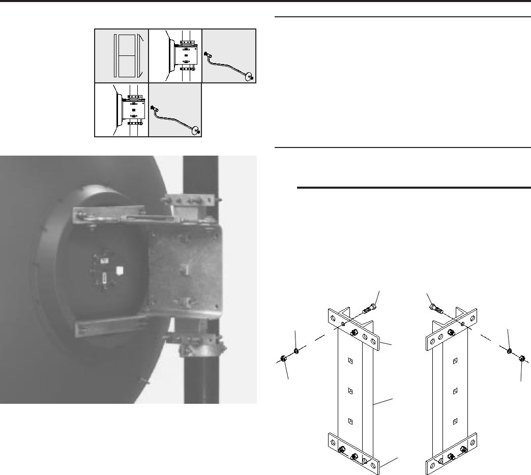
Figure 3. Assembly of Mounting Bracket
Assembly of Mounting Bracket
Attach the mounting angle assembly and the mount
angle to the main channel , as shown in Figure 3, using
M12 x 40mm long bolts, lockwashers & nuts. Ensure that
both are perpendicular to the main channel. (The main
channel may be mounted in either of two positions depend-
ing on which side of the pipe the antenna is to be mounted).
Fully tighten hardware.
M12 x 40mm lg
Bolts
Mounting Angle
Assembly
Main Channel
3
using M20 x 45mm long bolts, lockwashers & nuts. Fully
tighten hardware.
Attachment of Mounting Bracket Assembly
to Antenna. (Refer to Figures.2, 4 & 5). Attach
assembled mounting bracket to hinges at positions 'A' &
'B' using M20 x 45mm long bolts, lockwashers & nuts
and connect eyebolt to hinge assembly at position 'C'
using M12 x 45mm long bolt, lockwasher & nut. Do not
tighten hardware. Thread M20 locknut approximately
halfway along eyebolt, then add concave adjustment nut
and convex washer. Slip eyebolt through hole in mount
angle. Add other convex washer, concave adjustment
nut and locknut as shown ensuring that convex washers
and concave nuts engage properly.
Mounting Bracket
Attachment of Suspension Parts.
(Refer to Figures.2, 4 & 5). Attach hinges to the
reflector mounting ring at positions 'A', 'B' & 'C' in Figure 1,
4
5
Figure 4. Attachment of Mounting Bracket
Mount Angle
M20 Locknut
Convex
Washer
Concave Adjustment
Nut No.1
M20 Eyebolt
M12 x 45mm lg Bolt
Reflector
Mounting Ring
Figure 5. Antenna Elevation Adjustment Assembly
Concave Adjustment
Nut No.2
M20 Lockwasher
& Nut
Hinge
Reflector
Mounting Ring
M20 x 45mm lg
Bolt
M20 Lockwasher
& Nut
Elevation Hinge
Bracket
M12 Lockwasher
& Nut
M20 Locknut
M20 x 45mm lg Bolt
Attachment of Antenna Support Clamp
(Refer to Figures 2 & 6). Determine desired height
for antenna and attach antenna band clamps to mounting
pipe at required location using M12 x 40mm long bolts,
lockwashers & nuts. Fully tighten hardware.
Attachment of the Antenna to the Mounting Pipe
(Refer to Figures 2 & 7). Rest the lower end of the
main channel on the antenna support clamp. Attach an-
tenna to mounting pipe using M20 'U'-bolt, M12 'U'-bolt and
their respective lockwashers & nuts. Tighten the nuts on
the 'U'-bolts until the lockwashers begin to close. Roughly
align the antenna onto its operating path.
Figure 7. Attachment of Azimuth Adjustment Strut (6ft version)
7
6
M20 Lockwasher &
Nut
Reflector
Mounting Ring
'U'-Bracket
M20 x 45mm lg Bolt
M20 x 90 lg Bolt,
Lockwasher & Nut
M16 x 55 lg Coach
Bolt & Flatwasher
Setscrew
& Locknut
Azimuth Adjustment
Nut
Angle Bracket
Note : Holes should not be
drilled without prior approval
of the tower or support struc-
ture manufacturer.
M12 x 40mm lg Bolt,
Lockwasher & Nut
Band
Clamp
Ø115mm
Mounting
Pipe
Band
Clamp
Figure 6. Attachment of Antenna Support
Clamp
Determine Strut Orientation.
Suitable mounting points must be provided on the
tower or main support structure prior to installation of the
azimuth adjustment strut and the fixed strut (if required).
For structural efficiency, the struts should be installed par-
allel to the antenna axis (ie in the direction of final trans-
mission path). When it is not possible to mount the struts in
this manner due to tower or outrigger considerations, the
struts may be positioned anywhere within an angular 'cone'
relative to the reflector axis as shown in Figure 9.
Azimuth Adjustment Strut Installation.
Attach 'U'-bracket to reflector mounting ring at point
'D', as shown in Figure 6, using an M20 x 45mm long bolt,
lockwasher & nut. Attach the pre-drilled end of the azimuth
adjustment strut to the azimuth 'U'-bracket on the reflector
using an M20 x 90mm long bolt, lockwasher & nut as shown
in Figure 6. Do not fully tighten at this stage.
Assemble the azimuth adjustment components and the strut
clamp on to the free end of the strut as shown in Figure 6.
Position the azimuth adjustment nuts such that they are
approximately at the mid-point of the azimuth bolt threads.
Tighten the 'U'-bolt and clamp assembly set screws suffi-
ciently enough to prevent the assembly from falling off the
strut at this stage.
Rotate the antenna in azimuth until pointing (as closely as
possible) in the direction of the final transmission path.
Loosen the azimuth adjustment assembly 'U'-bolt and clamp
set screws and slide the assembly until the clamp can be
installed on a suitable tower member. Fully tighten the 'U'-
bolt nuts to secure the angle bracket to the strut. Ensure
that the tab of the azimuth bolt is secured against the strut
clamp using the locknut provided. Take up excessive slack
in the remaining hardware at this stage in order to perform
final azimuth and elevation adjustments.
8
Tower
Member
Ø18mm Hole for
M16 Bolt
9
Side Strut
Clamp Assembly
M16 Lockwasher
& Nut
Side Strut
'U'-Bolt
Elevation and Azimuth Adjustment.
Normally several alternating adjustments in eleva-
tion and azimuth will be required to achieve optimum trans-
mission path alignment. Begin by adjusting the antenna in
elevation using the concave faced nuts on the elevation
eyebolt until the antenna is as close as possible to its final
transmission path direction. Correct any azimuth mis-align-
ment by adjusting the azimuth adjusting strut. Repeat the
sequence as necessary.
Once alignment is achieved, carefully tighten all mount and
strut hardware, taking care not to disturb the antenna posi-
tioning. The following hardware tightening sequence is rec-
ommended.
4. Fully tighten bolt attaching elevation eyebolt to eleva-
tion hinge bracket.
5. Fully tighten the bolt passing through the azimuth 'U'-
bracket and strut.
6. Fully tighten bolt attaching fixed strut to mounting ring
(if applicable).
7. Tighten the strut clamp assembly of the azimuth strut
and then the clamp assembly of the fixed strut (if
required). Do this by first loosening the jam nuts. Next
tighten the setscrews until they touch the strut. Then
tighten them 1¼ turns more so that their cup points cut
into the strut. Tighten the locknuts against the bracket.
8. Fully tighten the nuts securing the clamp assemblies
to the tower members.
9. Finally re-check that all hardware has been tight-
ened.
M20 x 45mm lg Bolt
M12 X 35mm lg
Bolt
Azimuth
Adjustment
Assembly
Strut
An 13.5mm (max) Diameter
Clearance Hole in an Appro-
priate Tower Member (for
M12 Bolt) is Required.
Tower Member
(not supplied)
Bracket
Note : Holes should not be
drilled without prior approval
of the tower or support struc-
ture manufacturer.
Figure 8. Attachment of Azimuth Adjustment Assembly (4ft version)
M10 U Bolt
M10
Lockwashers &
Nuts
M10 x 50mm lg Bolt
Plate
Reflector Mounting
Ring
M20 Lockwasher
& Nut
M12 x 35mm lg
Bolt
M12 Lockwasher
& Nut
M10 Lockwasher
& Nut Strut Channel Pivot
10
1. Fully tighten the nuts on the two 'U'-bolts on the tower
mounting pipe
2. Fully tighten the mounting ring bolts at each of the
three elevation hinge brackets.
3. Fully tighten bolts attaching elevation hinge brackets
to mounting bracket.
M12 Lockwasher
& Nut
Hardware Check. Recheck all hardware to en-
sure that it has been correctly tightened during installation
procedure.
Corrosion Prevention. Paint the cut end of the
strut with a Zinc based paint (eg. 'Galvafroid') to prevent
corrosion.
11
Figure 9. Azimuth Strut Positioning
50
Azimuth Adjustment Strut
12
50
250
250
Figure 8. Attachment of Side Struts to Round
Tower Members
Clamp Attachment to Round Tower
Member (48 to 76mm Dia)
Invert Clamp for Round
Members (25 to 47mm Dia)
Strut may be attached to a Round Tower Mem-
ber of 25 to 76mm Diameter using Pipe Clamp
Assembly Part No. 33984-7. This Must be or-
dered separately

Item Description 4ft Qty* 6ft Qty*
1 Antenna azimuth adjustment 1 1
2 Front strut angle 1 -
3 U bracket 1 -
4 Strut plate 1 -
5 M12 U-bolt 1 1
6 M10 U-bolt 1 -
7 M20 U-bolt 1 1
8 Antenna support band 2 2
9 M12 lockwasher, gs 11 9
10 M12 hex nut, gs 11 9
11 M10 lockwasher, gs 3 -
12 M10 hex nut, gs 3 -
13 M10 x 50mm hex bolt, gs 1 -
14 M12 x 35mm hex bolt, gs 2 -
15 M12 x 40mm hex bolt, gs 6 6
16 M12 x 45mm hex bolt, ss 1 1
17 M12 lockwasher, ss 1 1
18 M12 nut, ss 1 1
19 M20 x 45mm hex bolt, gs 6* 7*
20 M20 x 90mm hex bolt, gs - 1
21 M20 lockwasher, gs 8* 9*
22 M20 nut, gs 8* 9*
23 M20 locknut, ss 2 2
24 Strut channel 1 -
25 Main channel 1 1
26 Strut 1 1
27 Strut clamp assembly - 1
28 Band clamp 2 2
29 Convex washer, ss 2 2
30 Concave nut, brass 2 2
31 Pivot bracket 2 2
32 Rod end eyebolt assy. 1 1
33 Mount angle 1 1
34 Mounting angle assy. 1 1
35 Hinge 2 1
36 Conductive grease 1 1
37 Vinyl gloves 2 2
ss/gs stainless steel/galvanized steel * Includes spares
Fastener Torque value in N·m (lb·ft ) for each fastener size
Size M5 M6 M8 M10 M12 M16
Stainless 4.5 7.7 18.7 39.2 65.1 161
steel (3.3) (5.7) (13.8) (28.9) (48) (118.7)
Galvanized 2.7 4.5 11.1 22 38 95
steel (2) (3.3) (8.1) (16.2) (28) (70.1)
Table 1. Mount Parts List
Table 2. Fastener Torque Specifications
Andrew Corporation
10500 West 153rd Street
Orland Park, IL U.S. A. 60462
Telephone: 708/349-3300
FAX (U.S.A.): 1-800/349-5444
TELEX: 25-3897
Customer Service, 24 hours: U.S.A. Canada Mexico: 1-800/255-1479
U.K.: 0800 250055 Republic of Ireland: 1 800 535358
Other Europe: +44 592 782 612
Printed in E.C. Oct99
Copyright © 1994 by Andrew Corporation

Tel: +972-3-6455733 Fax: +972-3-6455499
Installation Instructions
AN-0033-0, AN-0027-0, AN-0015-0
Feed Installation For Ceragon Antennas
0
CERAGON Ltd.
24 Raul Valenberg Street, Tel-Aviv, 69710, Israel
Home Page: www.ceragon.com
CERAGON, Sept-200
Bulletin 101773
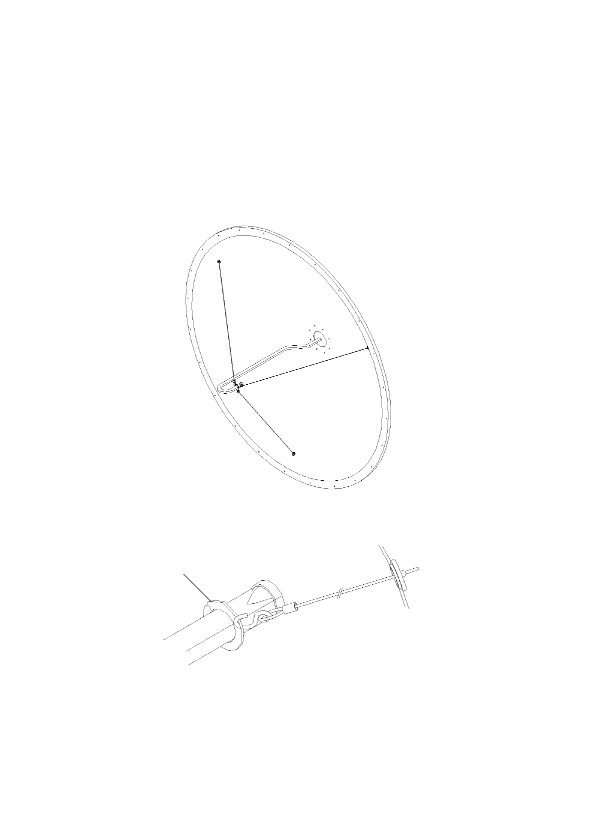
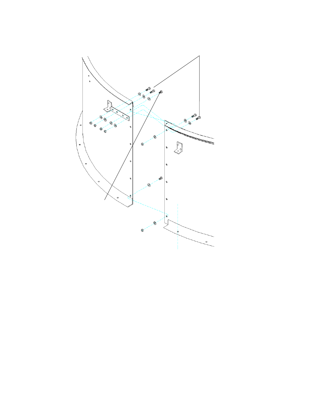
Feed Installation
for VHP4-240-G01 Antennas
Installation Instructions
1
2
Rear surface of
antenna reflector
2
Insert guy wire here
and bring back through
feed mounting hole
Antenna Assembly Sequence
Antenna
Feed
mounting
hole
VHP antenna 213
Description
Notice
The installation, maintenance, or removal of antenna sys-
tems requires qualified, experienced peronnel. This
installation instructions have been written for such person-
nel. Antenna systems should be inspected once a year by
qualified personnel to verify proper installation, mainte-
nance, and condition of equipment.
results of improper or unsafe installation practices.
Table 1. Feed Parts List
Item Description Qty
1 Feed Assembly 1
2 Guy Wire 3
3 M6x16lg SHCS, ss. 4*
4 M6 Lockwasher, ss. 4*
5 O-Ring 1*
6 Silicone Grease, tube 1*
7 Conductive grease, tube 2*
ss - Stainless Steel
* - Part of feed kit
Table 2. Fastener Torque Specifications
Fastener Torque value in N·m (lb·ft ) for each fastener size
Size M5 M6 M8 M10 M12 M16
Stainless 4.5 7.7 18.7 39.2 65.1 161
steel (3.3) (5.7)(13.8)(28.9) (48) (118.7)
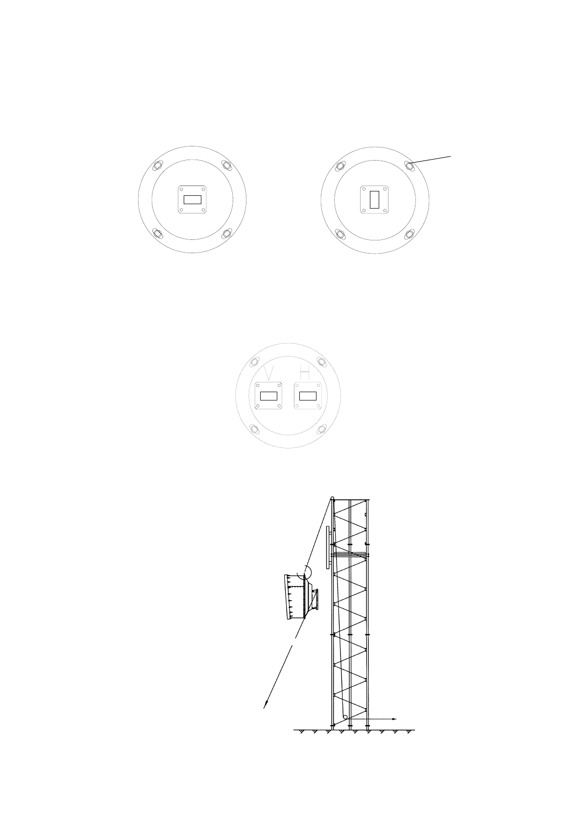
to be mounted into the reflector of the antenna.
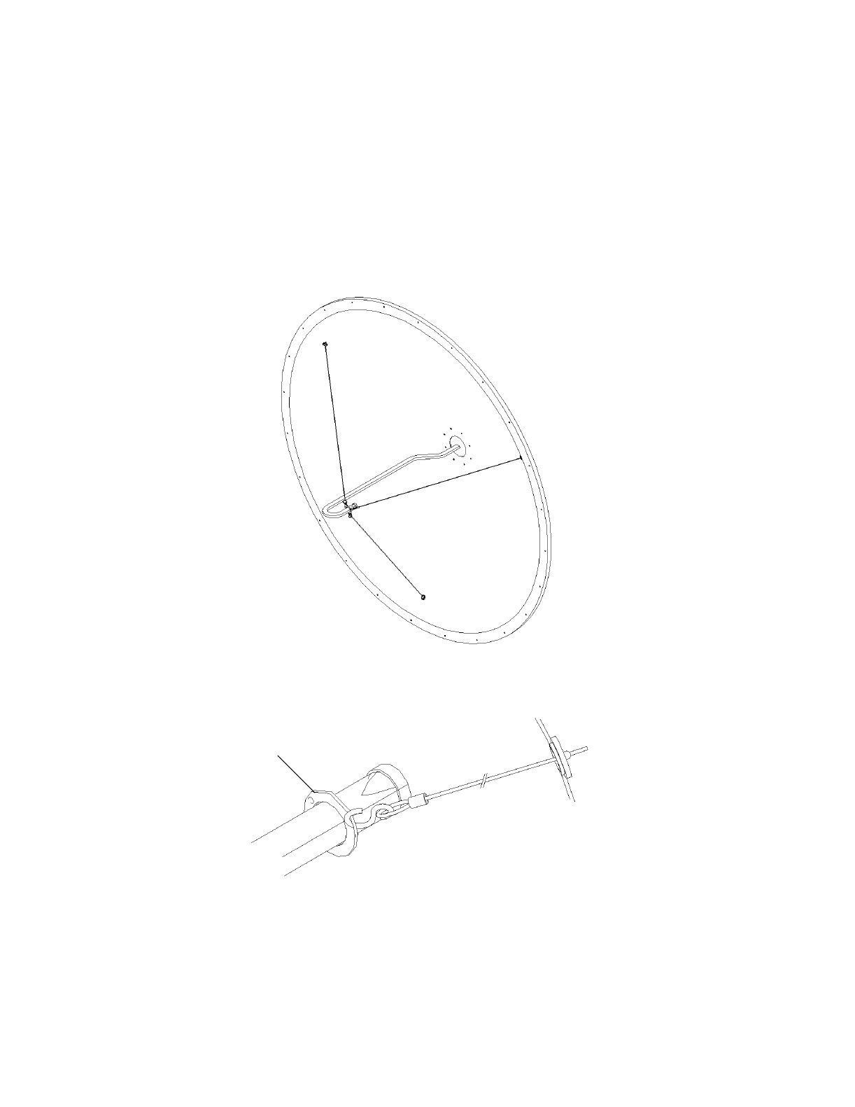
Included with the feed are guy wires. An notch on the feed
hub indicates the direction of polarization and the feed can
be rotated to adjust polarization.
This feed is designed to interface with a CERAGON RFU and
Ceragon disclaims any liability or responsibility for the
3
Feed
Feed
guy
ring
5
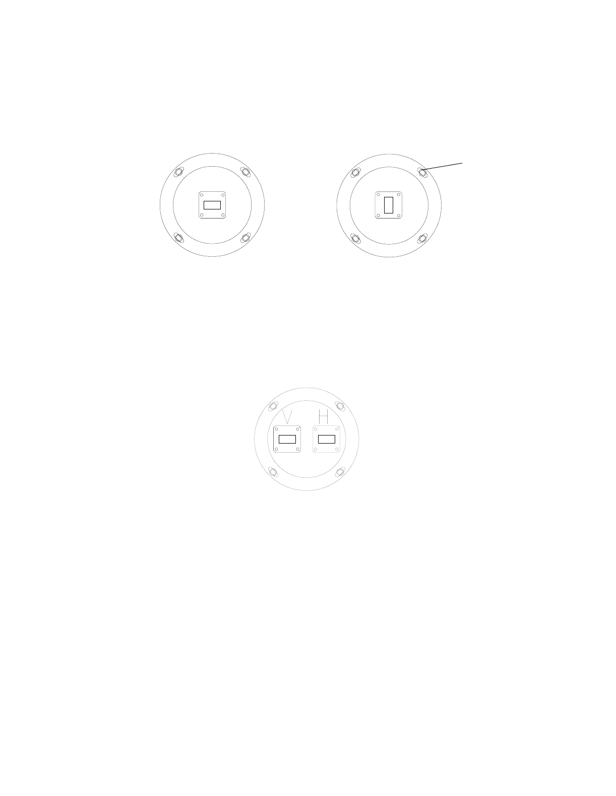
Polarization
indicator notch
Rotate feed hub to
adjust polarization
Remove 4 off M6
Cap Screws to
adjust polarization
Attach guy hooks
to feed guy
ring and pass
feed through feed
mounting hole
Vertically Polarized Application
Remove 4 off M6
Cap Screws to
adjust polarization
Polarization
indicator notch Rotate feed hub to
adjust polarization
Horizontally Polarized Application
4
Reflector
Apply conductive
grease (7) to these
surfaces
(See Warning)
1
43
Apply conductive
grease (7) to threads
(See Warning)
5
Apply silicone grease
(6) to O-Ring
Warning: Use protective wear to avoid skin contact with the conductive
grease. Keep away from mouth. Wash thoroughly after use with liberal
amounts of liquid soap and rinse with water. Do not store open near food or
food sources. Contents: oil, clay, and zinc dust.

Installation Instructions
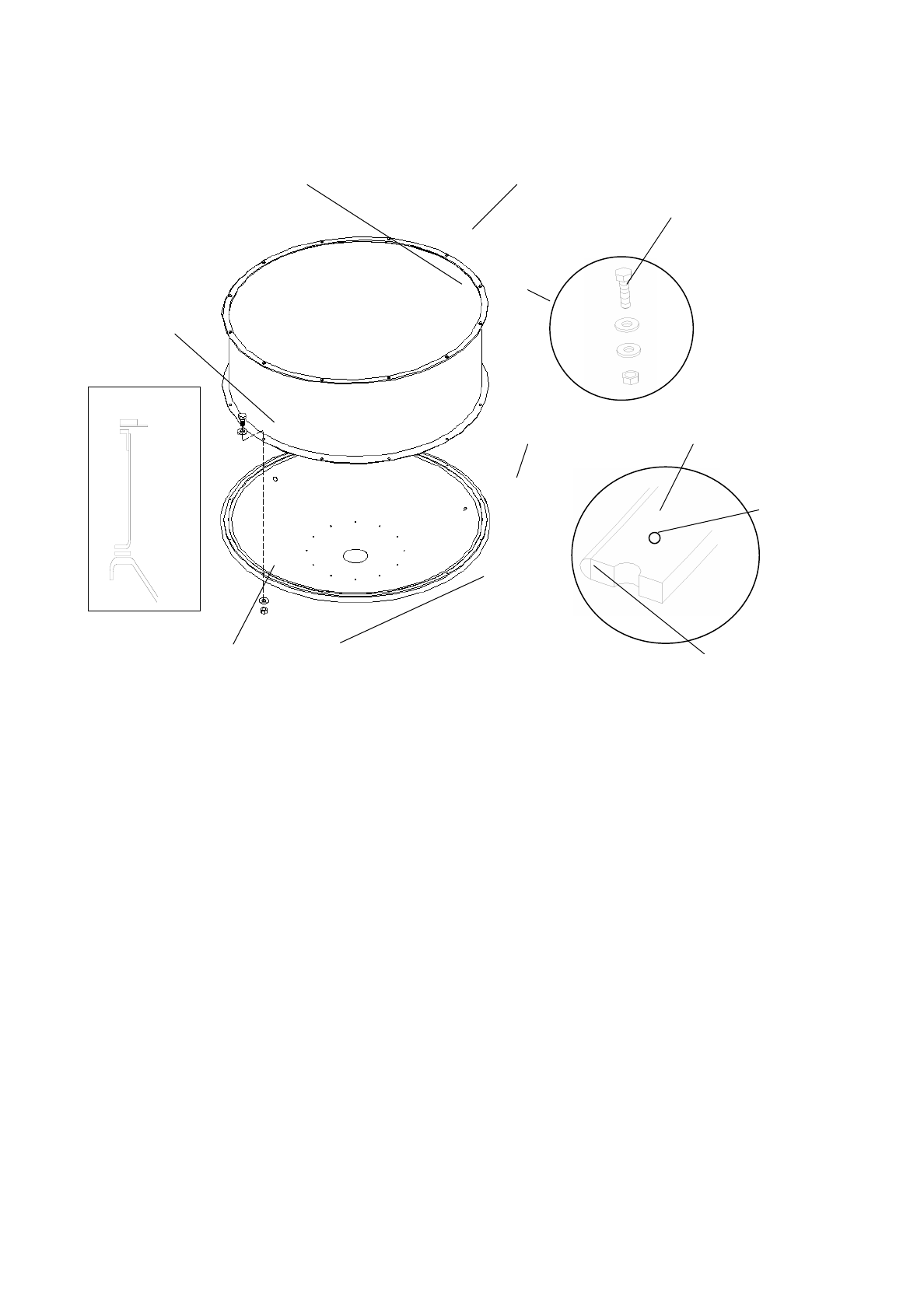
Shield-Radome
AN-0033-0, AN-0030-0, AN-0015-0
Tel: +972-3-6455733 Fax: +972-3-6455499
Ceragon Antennas
CERAGON, Sept-2000
CERAGON Ltd.
24 Raul Valenberg Street, Tel-Aviv, 69710, Israel
Home Page: www.ceragon.com
Bulletin 237288
Installation Instructions
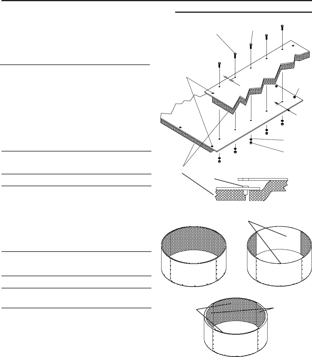
1
Reflector
mounting
holes
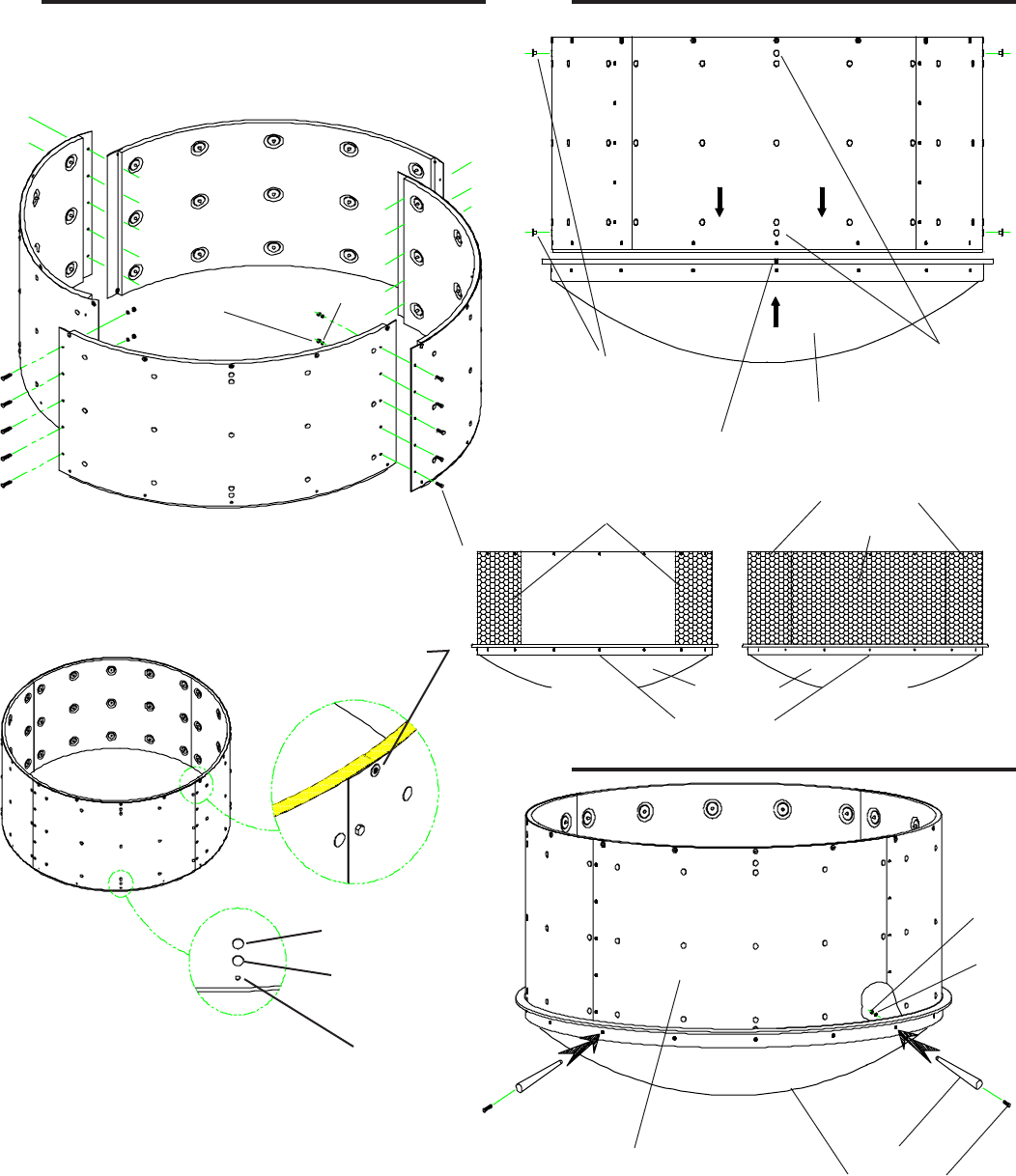
Loosely join ends of
shield segments with
five bolts, lock
washers, and nuts
1
3
2
VHP4
ValuLine™ Antenna
Shield-Radome
Radome
mounting
nut
14 mm
(0.55")
62.3 mm
(2.45")
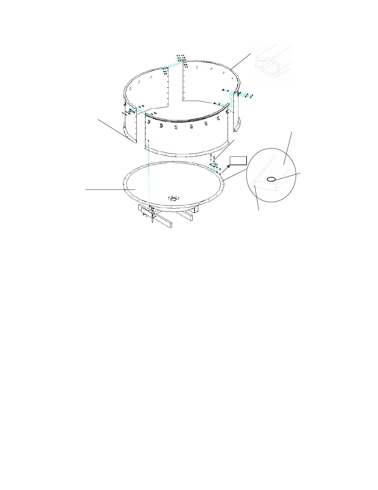
Absorber
Description
This four-segment shield with radome is designed to be mounted
on the reflector of the antenna to achieve high perfor-
mance. Signal absorber is fastened to the inside of the shield
segments. Some antennas require absorber on only two shield
segments and other antennas require absorber on all four
segments. Assembly and mounting hardware is included.
Notice
The installation, maintenance, or removal of antenna systems
requires qualified, experienced personnel. This installation
instructions have been written for such personnel. Antenna
systems should be inspected once a year by qualified personnel
to verify proper installation, maintenance, and condition of
equipment.
improper or unsafe installation practices.
Table 1. Shield-Radome Parts List
Item Description Part no. Qty*
1 M6 x 1-6g x 12 mm hex bolt, ss 204000-76 38
2 M6 lock washer 204003-5 56
3 M6 x 1-6H hex nut 204001-12 38
4 M6 flat washer 204002-14 18
5 M6 x 1-6g x 20 mm hex bolt, ss 204000-78 18
6 Hole plug 48504 8
7 Absorber clip 108953-1 4
8 Absorber washer 9862-10 4
9 Tapered pin (alignment tool) 224797 1
10 Angle adaptor 45840-1 1
11 Angle adaptor bolt 9953-23 1
* Includes spares
ss stainless steel
Table 2. Fastener Torque Specifications
Fastener Torque value in N·m (lb·ft ) for each fastener size
Size M5 M6 M8 M10 M12 M16
Stainless 4.5 7.7 18.7 39.2 65.1 161
steel (3.3) (5.7)(13.8)(28.9) (48) (118.7)
Full-absorber
antenna shield Half-absorber
antenna shield
Revision C
plain segments
Typical overlap
arrangement
Radome
mounting
nut
DCN L98/083
1" Absorber
0.5" Absorber
0.5"/1.0" Full-absorber
antenna shield (71WA Only)
Ceragon disclaims any liability or responsibility for the results of
2
4
Antenna top
Red tape: indicates
top of antenna.
Absorber clip (typ.)
Insert hole plugs (6) in
top and side drain holes.
Bottom drain holes
must remain open.
Insert the tapered pin (9) into the reflector
hole as shown. Pry the shield slightly to
align shield and reflector holes to receive
a bolt. Repeat at 3 opposite positions.
Insert shield into
reflector so that
mounting holes align
with rim holes
in reflector.
Position absorber segments
at sides of half-absorber antennas.
Drain hole plug
Assembled shield
arrangement
Reflector mounting
hole
3
Antenna shield
arrangement
Threaded insert for
radome attachment
32
1
Drain holes: align
with antenna top.
Full-absorber antenna
shield version shown
Position of red
tape
9
Reflector
Shield
assembly
Reflector
1
Fit loosely with
lockwasher (2)
and nut (3) in 4
opposite places
as shown then
tighten.
2
3
Half Absorber 0.5"/1.0" Absorber
0.5" Absorber
1.0" Absorber
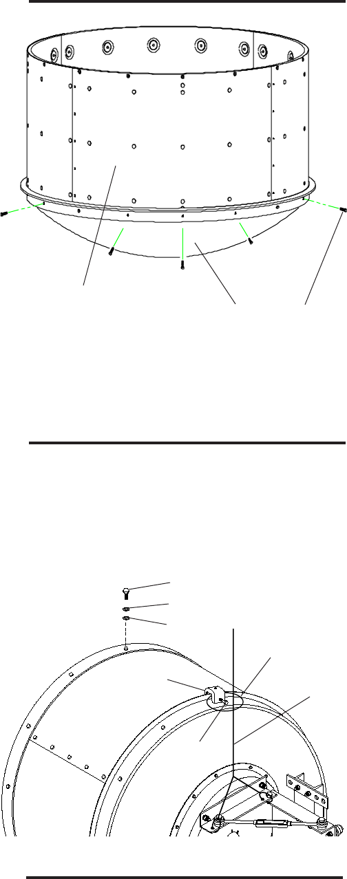
6
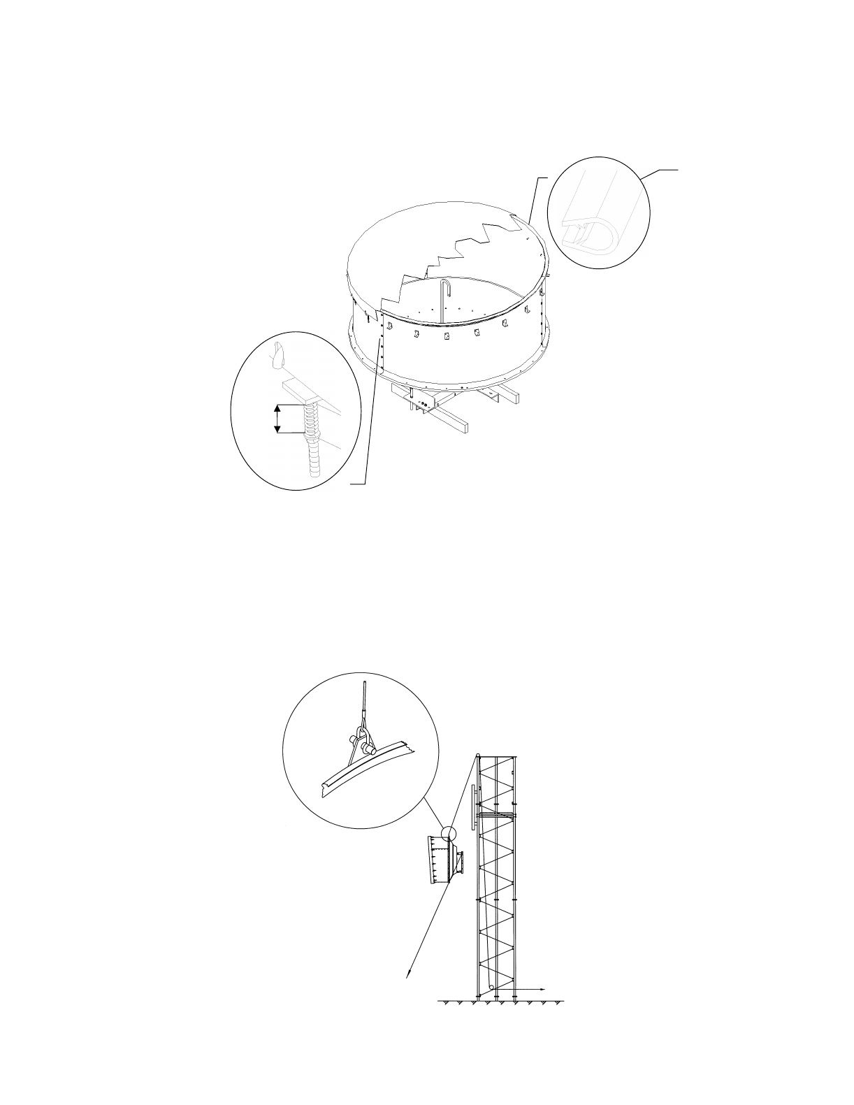
Position the radome on the shield with the
red flash nearest the top of the antenna.
Assemble radome to the shield with
bolts(5), lock washers (2), and flat washers (4).
Tightly attach the angle adaptor (10) to the top
of the reflector rim with the adaptor bolt (11)
to accommodate a hoist line choker.
4
5
2
11
Hoist line
choker
Hoist
line
5
Telephone: 708/349-3300
FAX (U.S.A.): 1-800/349-5444
TELEX: 25-3897
Andrew Corporation
10500 West 153rd Street
Orland Park, IL U.S. A. 60462
Printed in E.C. Sept'96
Copyright © 1993 by Andrew Corporation
Customer Service, 24 hours: U.S.A. • Canada • Mexico: 1-800/255-1479
U.K.: 0800 250055 • Republic of Ireland: 1 800 535358
Other Europe: +44 592 782 612
10
Fit bolts (1), lock washers (2) and nuts (3)
to remainder of holes of the reflector and
tighten. Tighten all shield segment
fastenings.
Reflector
Shield
assembly 1

Installation Instructions
AN-0015-0, AN-0016-0, AN-0027-0, AN-0029-0, AN-0030-0
Tel: +972-3-6455733 Fax: +972-3-6455499
Ceragon 2.5 ft Antenna Mount
CERAGON, Sept-2000
24 Raul Valenberg Street, Tel-Aviv, 69710, Israel
Home Page: www.ceragon.com
CERAGON Ltd.
Bulletin 237280
Installation Instructions
ValuLine™ Antenna
Mount
Notice
The installation, maintenance, or removal of antenna sys-
tems requires qualified, experienced personnel. This
installation instructions have been written for such person-
nel. Antenna systems should be inspected once a year by
qualified personnel to verify proper installation, mainte-
nance, and condition of equipment.
results of improper or unsafe installation practices.
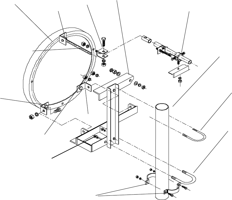
1
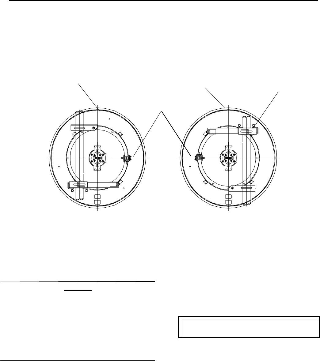
Tightly attach the
crossbars to the channel
for the desired offset of
the center of the antenna
16 16
17 17
13
28
Antenna center
offset left
(rear view)
Antenna center
offset right
(rear view)
19 19
13
Description
This mount is designed to be attached to an
antenna reflector and to provide for mounting the
antenna on a 4-1/2" (114 mm) diameter vertical tower
pipe. A strut is used to connect the bottom of the mount
to a tower member for extra stability.
The antenna center can be located 10.4" (264 mm) from
either side of the vertical tower pipe center, depending
on how the mount is assembled. This provides the
clearance necessary for the antenna feed components
and connections.
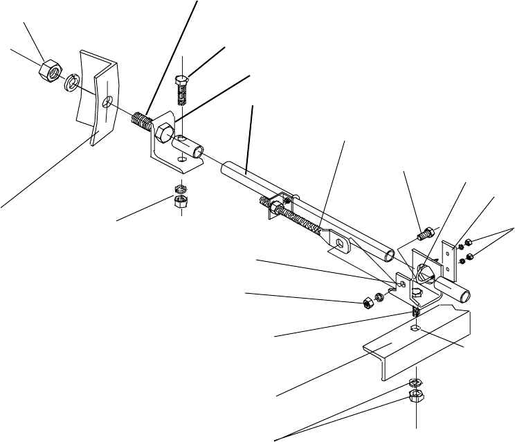
The mount includes separate turnbuckles for plus or
minus 15° azimuth adjustment and plus or minus 20°
elevation adjustment.
1 2
VP antenna
123
VHP antenna
Antenna Assembly Sequence
Ceragon disclaims any liability or responsibility for the
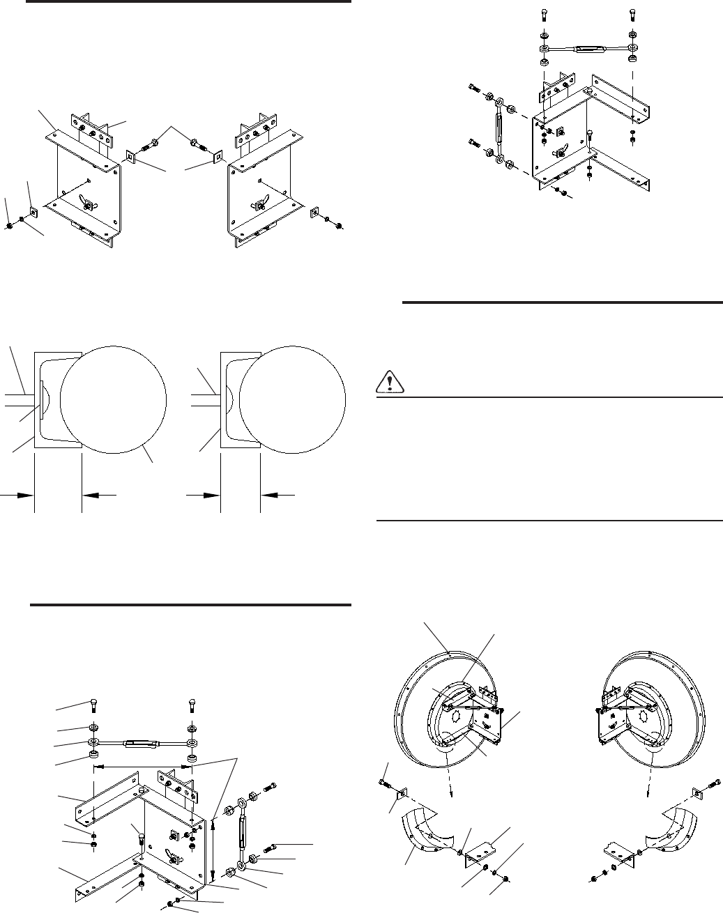
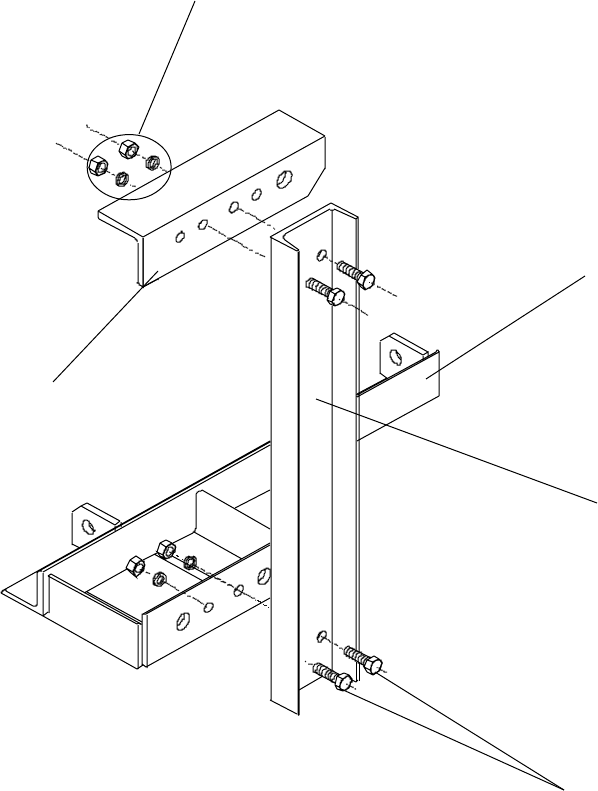
2
Loosely attach the base plate (26) to the
channel (28). Note: the channel
depth varies according to the origin of
manufacture, which determines whether
or not to use the spacer plate (8).
26
28
8
23
14
15
1Spacer plate:
add or discard
according to
channel depth
measurement
(see below)
Antenna center
offset right
Antenna center
offset left
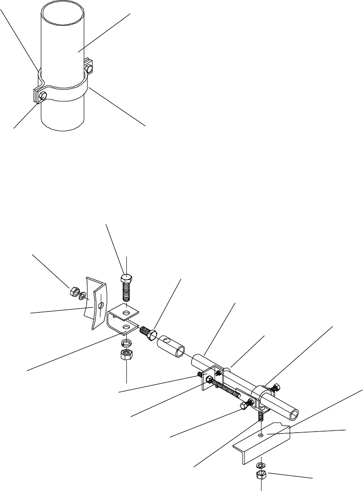
3
Very loosely attach both angles (27) to the
base plate (26). Loosen the jam nuts and set
both turnbuckles (9) with their eye centers
at the mid-travel position. Loosely
attach the turnbuckles as shown.
Antenna center
offset left
21
2
9
2
27
27
15
14
Set turnbuckle
eye centers
13.5 to 14" (344 to
356 mm) apart
22
14
15
20
2
9
3
14
15
26
4
Position the angles (27) of the mount on the
antenna mounting ring parallel to the antenna
top. The antenna top is indicated by red tape on
the reflector rim. Carefully align the mounting
holes and loosely add the attaching hardware.
Important: Partially tighten each bolt while checking to be
sure that the remaining untightened bolts are not
binding in the holes. If binding occurs, loosen
all partially tightened bolts. Then, slightly reposition the
mount to the reflector and repeat the procedure. If the
mount is improperly positioned on the reflector when
the bolts are tightened, distortion of the reflector
can occur. After the four bolts are partially tightened,
fully tighten them as given in Table 2.
Partially tighten the bolts holding the angles to the
base plate enough to compress the lock washers.
Red tape at
reflector top Antenna
mounting
ring
Base
plate
Antenna
mounting
ring
27
2719
425 27
25
16
17
Antenna center
offset right
Antenna center
offset left
Spacer plate
added Spacer plate
discarded
23
28
2"
(51 mm)
Tower
pipe 1.7"
(44 mm)
28
23
8
Antenna center
offset right
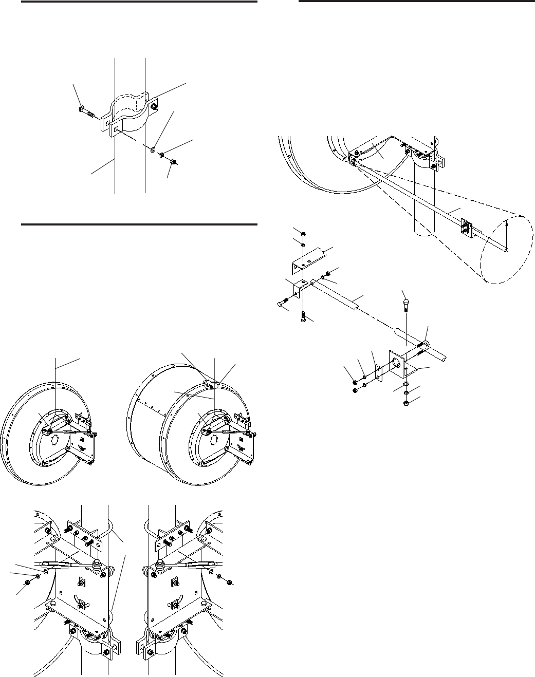
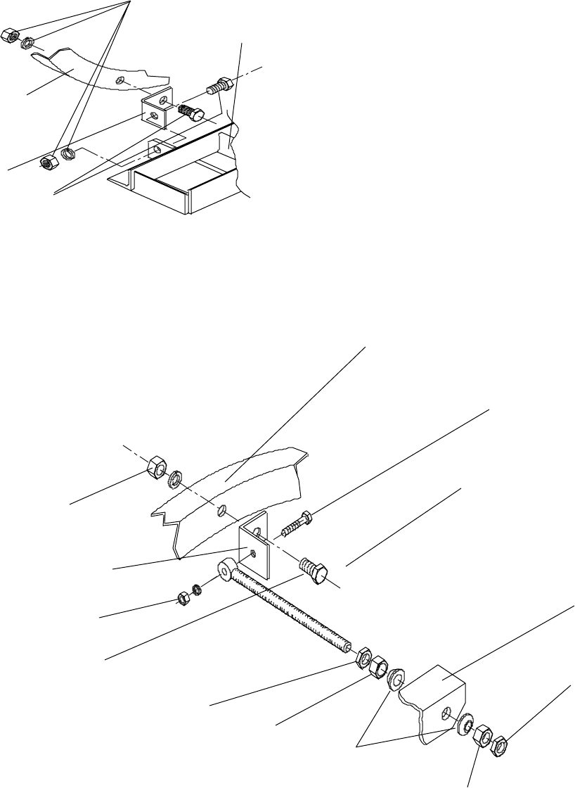
5 7
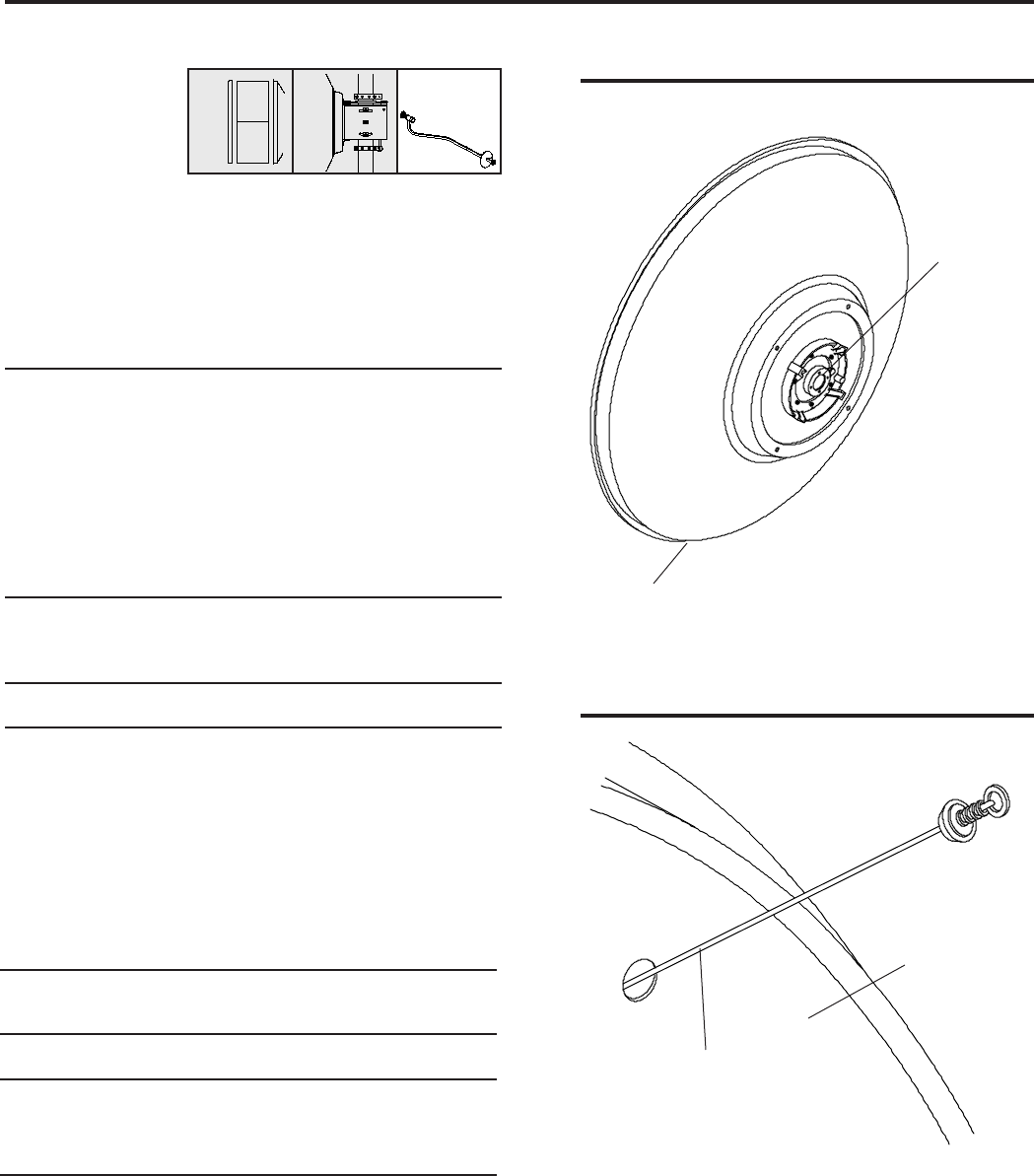
Tightly attach the support bands (12)
to the tower pipe in the antenna
mounting position. The antenna mount
channel will rest on these bands.
6
23 12
24
14
15
Tower pipe
Hoist
line
Hoist
line
Hoist line
choker
Angle
adaptor
27 27
24
14
15
10
Antenna center
offset left Antenna center
offset right
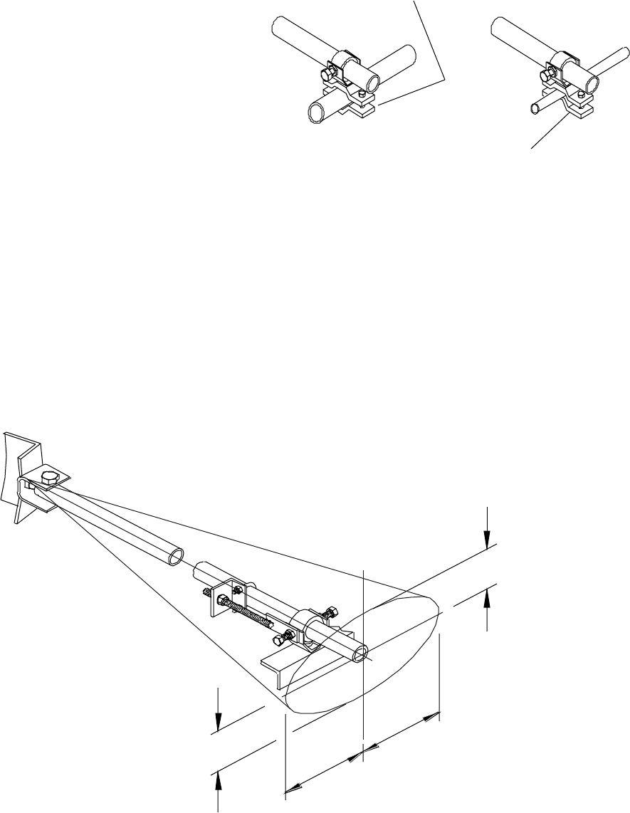
Very loosely attach the strut (29) to the mount
angle (27) with the front strut angle (5). Very loosely
attach the other end of the strut to a tower member
with the rear strut angle (6); attach this end so
that the strut is as parallel as possible to the
antenna axis for maximum stability. The deviation
angle from this parallel position should be no
more than 25° in any direction.
Leave all strut attaching hardware loose until after
elevation and azimuth adjustments are done.
Then, tighten the hardware according to Table 2.
25°
29
27
*Bolt requires a 13.5
mm (0.531") mounting
hole in tower member.
Consult with the tower
manufacturer
regarding advisability
of drilling into a tower
member, or for a
recommendation of a
special mounting
method.
15
14
5
27
17
16
18 22
29
22*
7
16
17
11
6
24
14
15
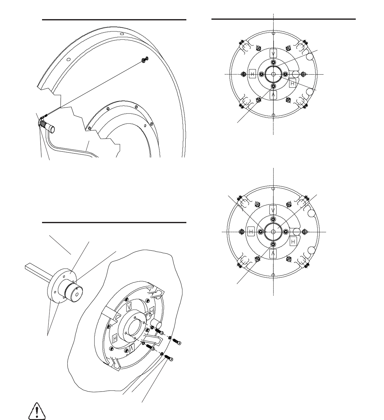
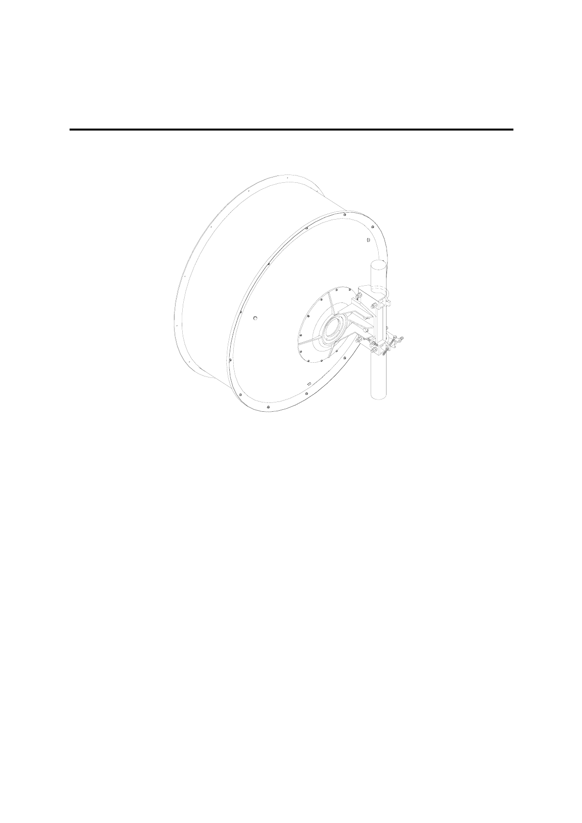
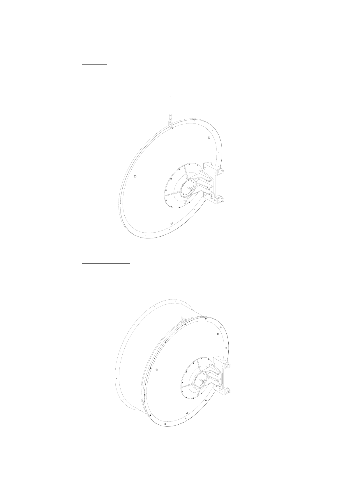
Install the feed according to Bulletin 237285 (feed
not shown for clarity). Attach hoist lines to the upper
mount angle (27) as shown: add a hoist line choker
through the angle adaptor of a shielded antenna.
Raise the antenna to the tower pipe and position
it on the support bands as close to its
operating position as possible. Tightly attach the
mount to the tower pipe with two U-bolts (10).
Andrew Corporation
10500 West 153rd Street
Orland Park, IL U.S. A. 60462
Telephone: 708/349-3300
FAX (U.S.A.): 1-800/349-5444
TELEX: 25-3897
Customer Service, 24 hours: U.S.A.
•
Canada
•
Mexico: 1-800/255-1479
U.K.: 0800 250055
•
Republic of Ireland: 1 800 535358
Other Europe: +44 592 782 612
Printed in U.S.A. 3/94
Copyright © 1994 by Andrew Corporation
Table 1. Mount Parts List
Item Description Part no. Qty*
1 Square washer 224349 3
2 Bevel washer, thin 224322-1 6
3 Bevel washer, thick 224322-2 2
4 Rectangular washer 224348 4
5 Front strut angle 224422 1
6 Rear strut angle 224406 1
7 Strut plate 224410 1
8 Spacer plate 224479 3
9 Turnbuckle 224403-1 2
10 M12 U-bolt 204031-1 2
11 M10 U-bolt 204031-3 1
12 Antenna support band 42922A-1 2
13 Crossbar 224320 2
14 M12 lock washer 100522-45 18
15 M12 hex nut 100526-45 18
16 M10 lock washer 100522-39 12
17 M10 hex nut 100526-39 12
18 M10 x 50 mm hex bolt, gs 100534-63 1
19 M10 x 35 mm hex bolt, gs 100534-36 8
20 M12 x 70 mm hex bolt, gs 100535-84 2
21 M12 x 50 mm hex bolt, gs 100535-48 2
22 M12 x 35 mm hex bolt, gs 100535-21 4
23 M12 x 45 mm carriage bolt, gs 204026-2 5
24 M12 flat washer 100521-45 7
25 M10 flat washer 100521-39 8
26 Base plate 224321 1
27 Angle 224766 2
28 Channel 224324 1
29 Strut 224409 1
* Includes spares
gs galvanized steel
Table 2. Fastener Torque Specifications
Fastener Torque value in N·m (lb·ft ) for each fastener size
Size M5 M6 M8 M10 M12 M16
Galvanized 2.7 4.5 11.1 22 38 95
steel (2) (3.3) (8.1) (16.2) (28) (70.1)
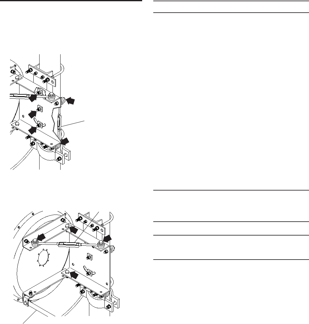
8
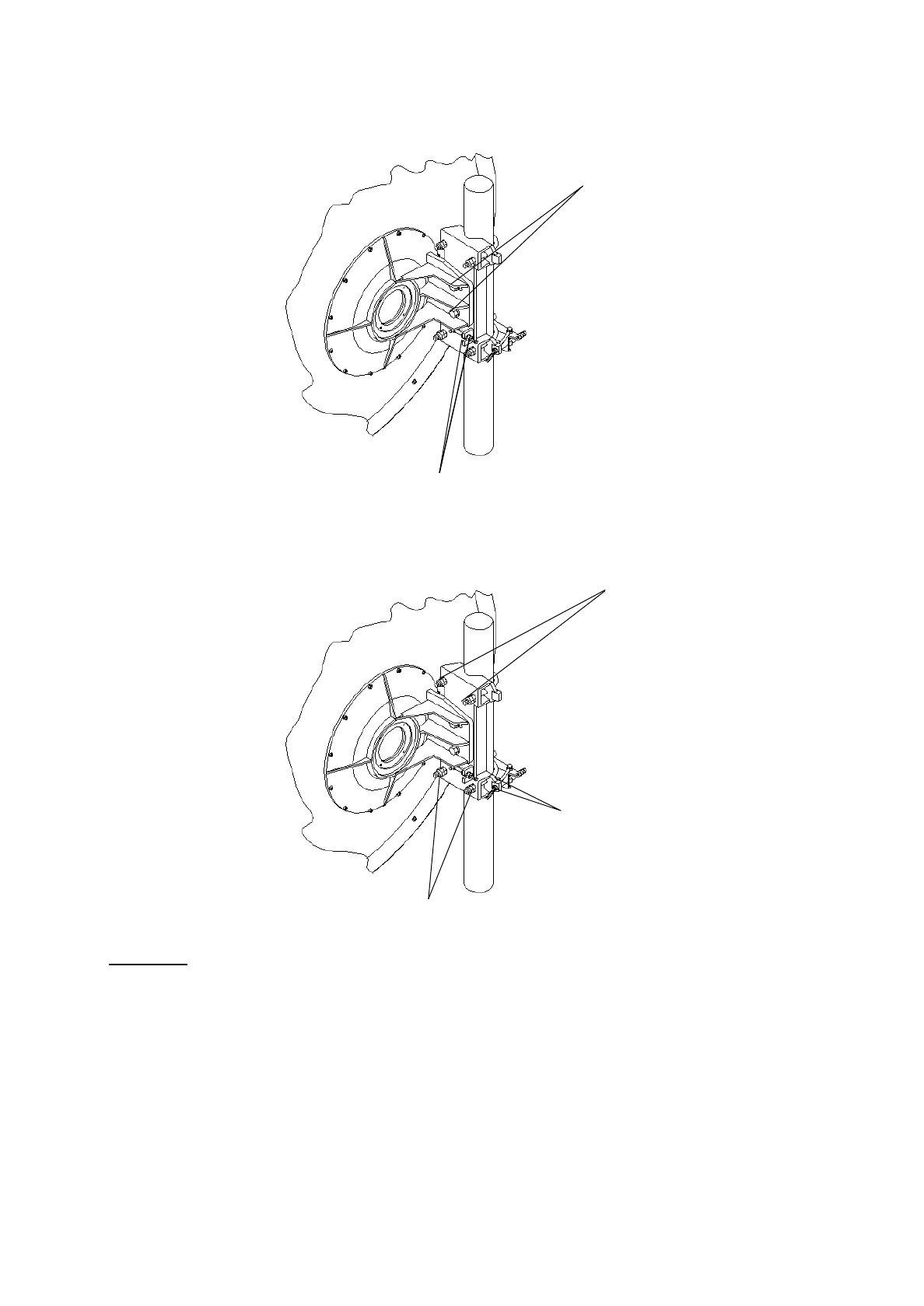
Adjust elevation and azimuth. Make sure
that all strut attachment hardware is
loosened before making either adjustment.
Tighten turnbuckle jam nuts to hold the
adjustments. Then, tighten the remaining
adjustment hardware according to Table 2.
Elevation
Loosen bolts indicated
by arrows and
rotate turnbuckle
Loosen jam nuts
and rotate
turnbuckle
Azimuth
Loosen bolts indicated
by arrows and
rotate turnbuckle
Strut: loosen all
attaching hardware
for elevation or
azimuth adjustment
Loosen jam nuts
and rotate
turnbuckle

Installation Instructions
Tel: +972-3-6455733 Fax: +972-3-6455499
For AN-0014-0, 4-foot Antennas
CERAGON, Sept-2000
CERAGON Ltd.
24 Raul Valenberg Street, Tel-Aviv, 69710, Israel
Home Page: www.ceragon.com
1(9)
Installation Instructions
4-foot Antenna AN-0014-0
These Installation Instructions are valid for antennas in the following version:
• reflector ∅ 1,2 m (4 ft)
• waveguide feed single or dual polarized
• pipe mount for installation on pipe ∅115mm
• antenna offset to the left or the right
• standard installation with offset to the left
• safety collar for easy installation
• 2 spindles for fine adjustment of azimuth ± 5° and elevation of ± 10°
• reflector (SP-Types)
• reflector with shroud, shroud aperture covered by a radome
(SU- and SD-Types)
It is important to mount the antenna exactly as described in these installation instructions.
The installed antenna shall be inspected once per year by qualified personnel .
These installation instructions have been written for qualified, skilled personnel.
We reserve the right to alter details, especially with respect to technical improvement.
Ceragon disclaims any responsability for the result of improper or unsafe installation.
2(9)
1. Tools required for installation
Tools are not included with antenna:
• Hoisting device for 250 daN
• Shackle
• 2 ropes
• Water balance and compass
• Mallet
• Wrenches for hexagon bolts:
M5(8), M6(10), M10(17), M12(19), M14(21), M16(24)
(values in brackets=openings of spanners)
• Torque wrench from 0,5 to 15 daNm
• Nail set or punch for ∅6mm.
2. Assembly of the mount
For easy operation of the bolted joints, « Anti Seize »Installation Paste should be
applied to all threads of bolts and fine adjustment spindles.
After this, keep the lubricated threads free of dust and dirt!
Fastener torque specification see table attached!
screw M16X55
washer 17 ∅ 40x6
screw M16X55
washer 17 ∅ 30x3
ELEVATION spindle M10X100
2 brass nuts M10
2 washers 10.5
AZIMUTH spindle M8X200
2 washers 8.4
2 brass nuts M8 2 U-Bolts M14
4 washers 15
8 nuts M14
screw M8X30
washer 8.4
sl nut M8
safety collar
U-Bolt M10
2 washers 10.5 ∅ 30
4 nuts M10
3(9)
3. Antenna offset
Offset left
Offset right
Rotate the reflector and the tower mount 180 deg
4(9)
4. Assembly of the shroud and the planar radome (only SU-and SD-Types)
* for spots free of paint 90 deg from TOP (left and right) add 2 serrated lock washers A6.4
• The rim of the reflector must be clean and dry
• Stick on the RF gasket tape 360 deg in a way, that
all mounting holes are covered by the tape and
the wire mesh is directed to the center of reflector
• position the shroud -clean and dry- on inside of the reflector.
antenna offset to the left
TOP shroud to TOP reflector
or
antenna offset to the right
TOP shroud oposite to TOP reflector
TOP planar radome
12 screws M6 x 20
24 washers 6.4 ∅ 18mm
12 sl nuts M6
TOP
Offset to the left RF gasket tape, self adhesive
∅ 6 mm punched
after positioning of
the shroud
wire mesh towards
center of reflector
reflector, complete with casting mount
12 screws M6 x 25
24 washers 6.4 ∅ 18mm*
12 sl nuts M6
TOP
Offset to the right
5(9)
5. Lifting of antenna
5.1 SP-Type
• Fix a shackle in the rim of the reflector. The diameter of the hole is 8mm.
• Lift the antenna carefully.
5.2 SD and SU-Type
• Fix a lifting sling at the shroud near the reflector.
• Lift the antenna carefully.
6(9)
6. Feed installation
The feed is a precision component which should be handled with special care
during installation. For instance, always carry the feed, supporting both ends.
Any damage may degrade the antenna’s performance. Repair of feeds is not
possible in the field.
6.1. Guy Wire Assemblies
• Insert the 3 guy wires in the mounting holes on the rear of the reflector.
• Move the feed assembly partway through the connecting ring.
• Hook the guy wires into the rotatable guy ring
• Move the feed and fix it, with the 4 screws M5, in the connecting ring.
rotatable feed guy ring
7(9)
6.2. Polarization Choice
6.2.1 Single polarization
• unscrew the 4 screws M5
• carefully rotate the feed 90 degrees
• lock the 4 screws M5
6.2.2 Dual polarization
7. Hoisting on tower
8. Elevation adjustment
4 screws M5
4 washers 5.3
2 ropes fixed on the mount
for optimal balance
Antenna TOP
Vertica Horizontal
Antenna TOP
8(9)
9. Azimuth adjustment
Important
:
After azimuth adjustment, lock the first nut on the U-bolts with a torque of
95Nm, then the second lock nut is fixed against the first one
.
Don’t use two wrenches to fix
the second nut.
Loosen nuts
Loosen bolts
Loosen nuts and adjust
elevation
Loosen nuts
Loosen nuts and
adjust azimuth
9(9)
11. Polarization adjustment
Loosen 4 screws M5 and adjust polarization
12. Final Check
When the installation of the antenna has been completed, it is necessary to make sure that
the installation instructions have been followed in all aspects.
It is especially important to check that all bolted joints are tightly locked.

Installation Instructions
For 6-foot Antennas
8 Hanechoshet Street, Tel-Aviv, 69710, Israel
Tel: +972-3-6455733 Fax: +972-3-6455499
CERAGON, Sept-2000
CERAGON Ltd.
Home Page: www.ceragon.com
1(10)
Installation Instructions
6-Foot Antenna
These Installation Instructions are valid for antennas in the following version:
• reflector ∅ 1,8 m (6 ft)
• waveguide feed single or dual
polarized
• pipe mount for installation on pipe
∅115mm
• antenna offset to the left or the right
• safety collar for easy installation
• 2 spindles for fine adjustment of
azimuth and elevation of ± 5 deg
• reflector (SP-Types)
• reflector with shroud, shroud
aperture covered by a radome (SU-
and SD-Types)
It is important to mount the antenna exactly as described in these installation instructions.
The installed antenna shall be inspected once per year by qualified personnel .
These installation instructions have been written for qualified, skilled personnel.
We reserve the right to alter details, especially with respect to technical improvement.
Ceragon disclaims any responsibility for the result of improper or unsafe installation.
2(10)
1. Tools required for installation
Tools are not included with antenna:
• Hoisting device for 250 daN
• Shackle
• 2 ropes
• Water balance and compass
• Mallet
• Wrenches for hexagon bolts:
M5(8), M6(10), M10(17), M12(19), M14(21), M16(24), M20(30)
(values in brackets=openings of spanners)
• Torque wrench from 0,5 to 25 daNm
• Nail set or punch for ∅6mm.
2. Assembly of the mount
For easy operation of the bolted joints, « Anti Seize »Installation Paste should be
applied to all threads of bolts and fine adjustment spindles.
After this, keep the lubricated threads free of dust and dirt!
Fastener torque specification see table attached!
Bracket left
screw M16X50
washer 17
sl nut M16
ELEVATION spindle M16
2 brass nuts M16
2 spherical washers C17
2 conical seats D19
EL-bracket
4 screws M12X35
8 washers 13 ∅24
4 sl nuts M12 3 U-Bolts M14
with
6 washers 15
12 nuts M14
Azimuth clamp
AZIMUTH spindle M12
2 brass nuts M12
2 spherical washers C13
2 conical seats D14.2
2 washers 13 ∅32
6 screws M12X35
6 washers 13 ∅24
6 washers 13 ∅40
6 sl nuts M12
2 screws M20X50
2 washers 21
2 sl nuts M20
Bracket right
2 washers 13 ∅24
2 brass nuts M12
3(10)
3. Antenna offset
Offset left
Offset right
4. Assembly of the shroud (only SU-and SD-Types)
4(10)
* for spots free of paint 90 deg a side TOP (left end right) additionnaly use 2 serrated
lock washers A6.4
• The rim of the reflector must be clean and dry
• Stick on the RF gasket tape 360 deg in a way, that
all mounting holes are covered by the tape and
the wire mesh is directed to the center of reflector
• position the shroud -clean and dry- into the reflector.
5. Shroud Sections Attachment
24 screws M6X25
48 washers 6.4 ∅18*
24 sl nuts M6
Reflector,
complete with
mount
Wire mesh directed
to center of reflector
RF gasket tape
self adhesive
TOP
Hoisting eye
dismounted
∅ 6mm
(punched after
positioning of the
shroud)
Edge protector
5(10)
4 screws M6X25
4 sl nuts M6
8 washers 6.4 ∅18
6 screws M6X16
6 sl nuts M6 short section
12 washers 6.4 ∅18
or
7 screws M6X16
7 sl nuts M6 long section
14 washers 6.4 ∅18
6(10)
6. Feed installation
The feed is a precision component which should be handled with special care
during installation. For instance, always carry the feed, supporting both ends.
Any damage may degrade the antenna’s performance. Repair of feeds is not
possible in the field.
6.1. Guy Wire Assemblies
• Insert the 3 guy wires in the mounting holes on the rear of the reflector.
• Move the feed assembly partway through the connecting ring.
• Hook the guy wires into the rotatable guy ring
• Move the feed and fix it, with the 4 screws M5, in the connecting ring.
rotatable feed guy ring
7(10)
6.2. Polarization Choice
6.2.1 Single polarization
• unscrew the 4 screws M5
• carefully rotate the feed 90 degrees
• lock the 4 screws M5
6.2.2 Dual polarization
4 screws M5
4 washers 5.3
Antenna TOP
Vertical Horizontal
Antenna TOP
8(10)
7. Installation of the planar radome (only U and D-Types)
Take care to avoid kinking of planar radomes during installation. Kinking would
destroy the radomes, which are non-repairable!
• Unpack the radome and carefully stretch it over the shroud aperture.
• Orient the drainhole grommet exactly to the bottom point of antenna, opposite TOP.
• Attach J-bolts with springs and smooth radome down as the springs are attached, but do
not displace the edge protector.
• Align the length of springs to approx. 135 mm at each J-bolt, this will provide proper
radome tension.
8. Hoisting on tower
2 ropes fixed on the mount
for optimal balance
Edge protector
135
mm
9(10)
9. Elevation adjustment
10. Azimuth adjustment
Important
:
After azimuth adjustment, lock the first nut on the U-bolts with a torque of
95Nm, then the second lock nut is fixed against the first one
.
Don’t use two wrenches to fix
the second nut.
11. Polarization adjustment
Loosen nuts and adjust
elevation
Loosen
elevation pivots
Loosen nuts and adjust
azimuth
Loosen nuts of the U-
bolts
10(10)
Loosen 4 screws M5 and adjust polarization
12. Final Check
When the installation of the antenna has been completed, it is necessary to make sure that
the installation instructions have been followed in all aspects.
It is especially important to check that all bolted joints are tightly locked.

Supplement To
Installation Instructions
For 4-foot and 6-foot Antennas
Tel: +972-3-6455733 Fax: +972-3-6455499
CERAGON, Sept-2000
CERAGON Ltd.
24 Raul Valenberg Street, Tel-Aviv, 69710, Israel
Home Page: www.ceragon.com
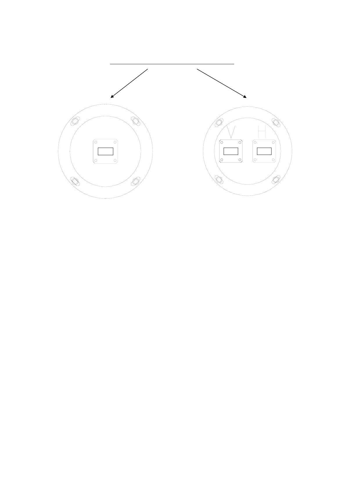
Installation Instruction
Supplement for Installation Instruction 4 and 6-foot Antennas
• Loosen the 4 bolts M5x25
• Adjust the feed carefully.
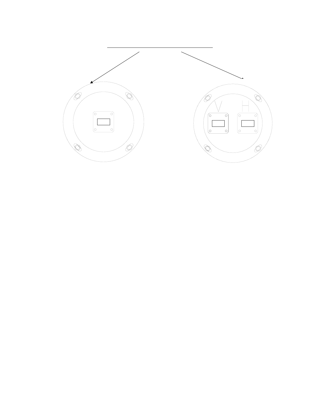
- for the vertical polarization, V to TOP-direction
- for the horizontal polarization, H to TOP-direction
• Lock the 4 screws M5x25
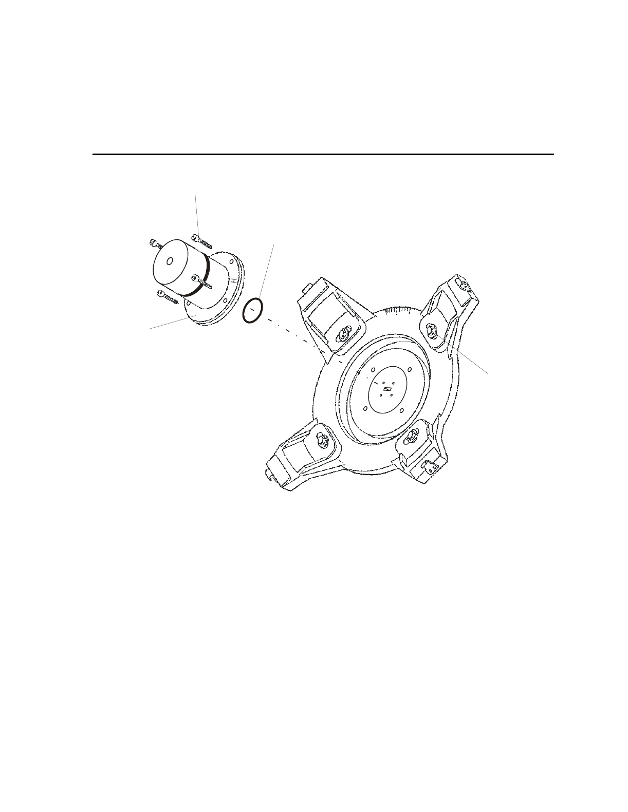
Connection of a standard wave guide flange
• Loosen the 4 bolts M3x12
• Remove the Adaptation and the O-Ring carefully from the feed
Attention: UBR-flange on antenna feed.
-5°
+5°
Adapter
O-Ring
M3 x 12
M5 x 25
V
Polarization adjustment with Ceragon-Adaptation

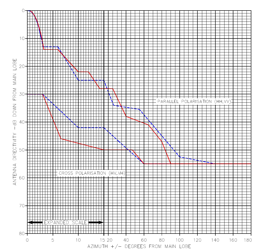
Radiation Pattern Envelope
Antenna Type Number AN – 0031-0
1 Foot Antenna 17.7 – 19.7 GHz Single Polarized
Gain: 34.0 dBi at 18.7 GHz
Legend:
Envelope for a horizontally polarized antenna (HH, HV)
Envelope for a vertically polarized antenna (VV,VH)
Tel: +972-3-6455733 Fax: +972-3-6455499
CERAGON, Sept-2000
CERAGON Ltd.
24 Raul Valenberg Street, Tel-Aviv, 69710, Israel
Home Page: www.ceragon.com
®
Return to Index