Ceragon Networks GNT-FA1500-28 Point-to-Point digital radio User Manual FibeAir cover
Ceragon Networks Ltd. Point-to-Point digital radio FibeAir cover
UserManual.wiki
>
Ceragon Networks
>
GNT-FA1500-28 User Manual
>
chapter 3
Contents
1.
chapter 4
2.
chapter 5
3.
chapter 2
4.
chapter 3
chapter 3
Navigation menu
Upload a User Manual
Namespaces
Wiki Guide
HTML
PDF
Info
Views
User Manual
Discussion / Help
Navigation
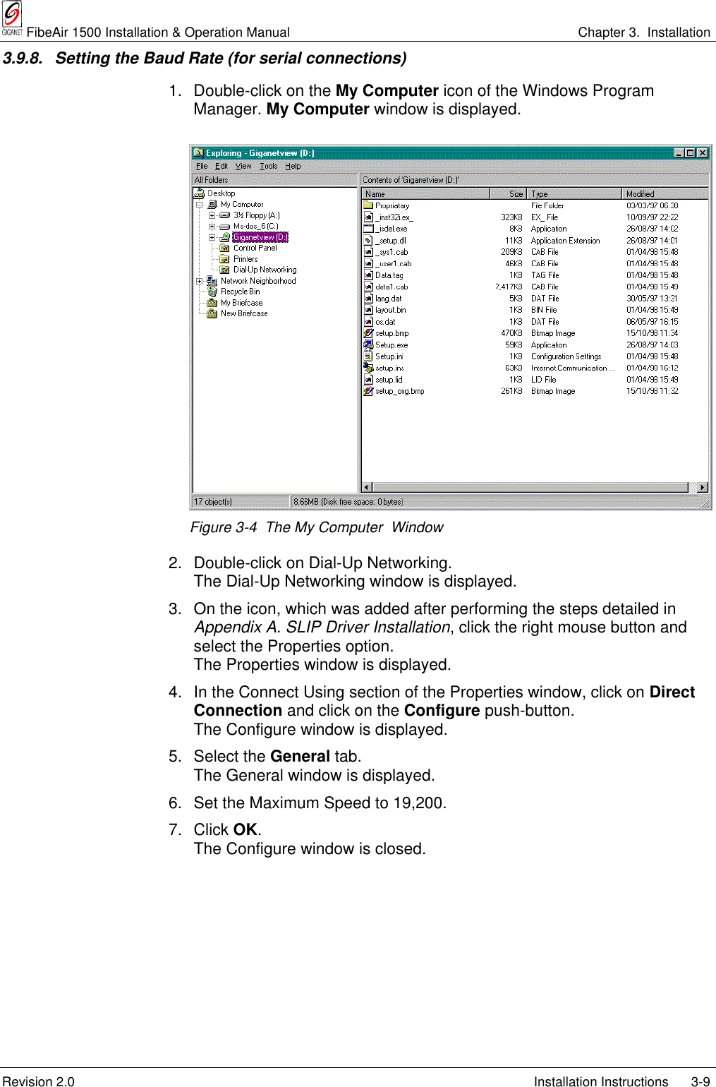
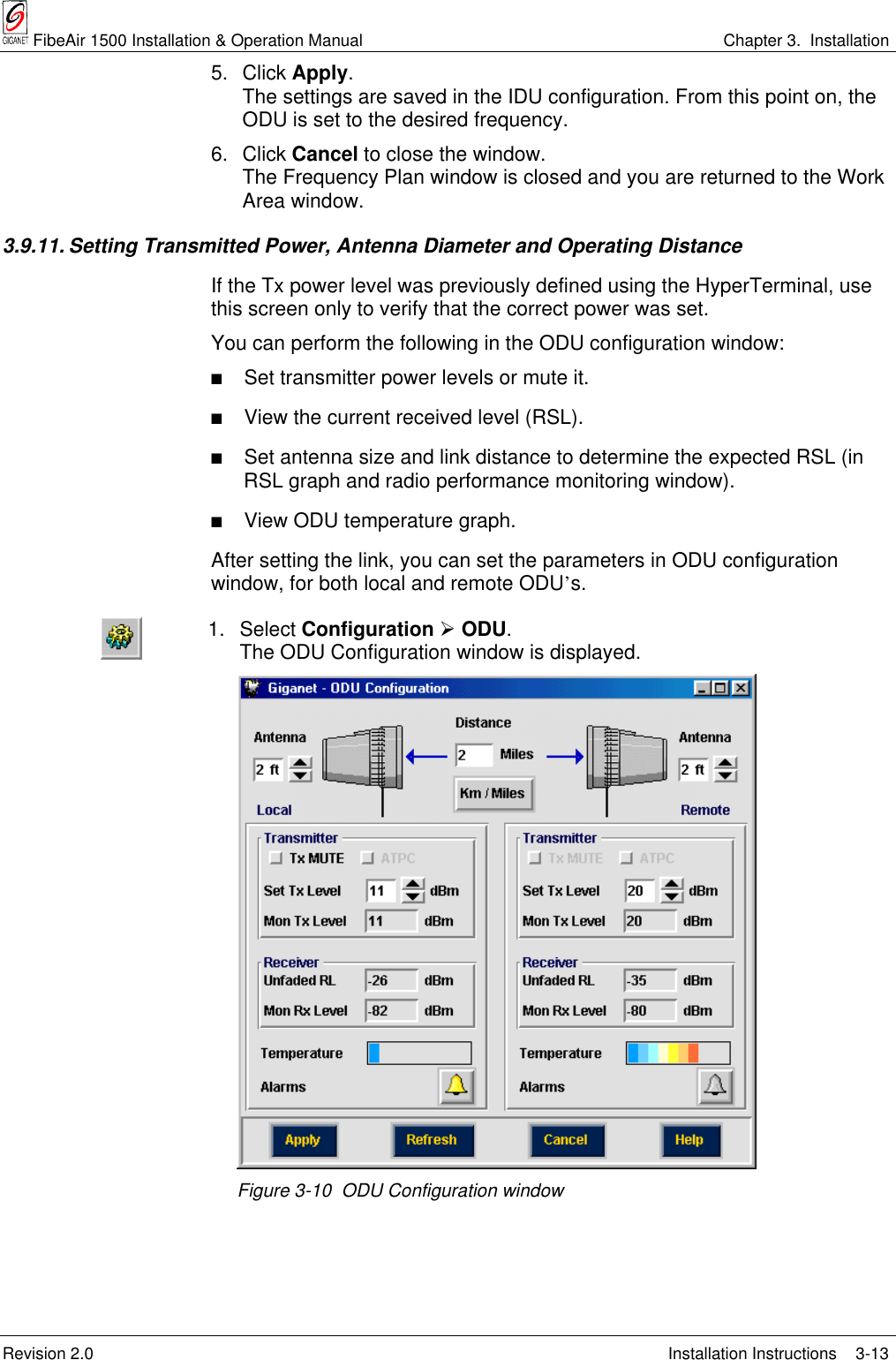
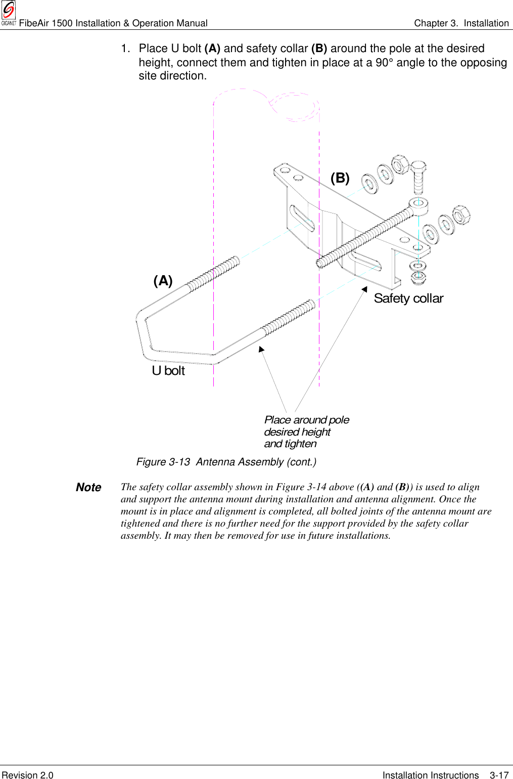
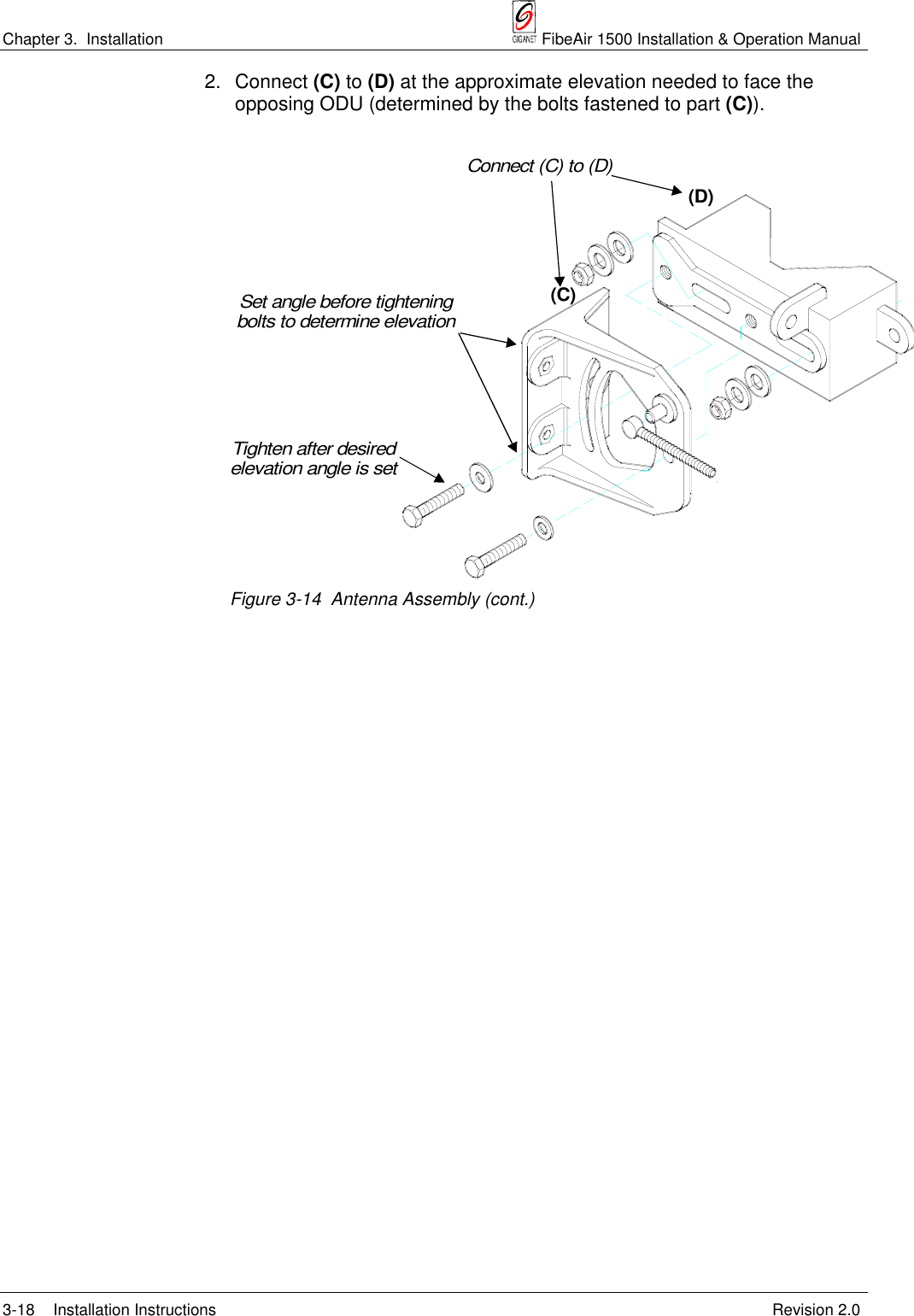
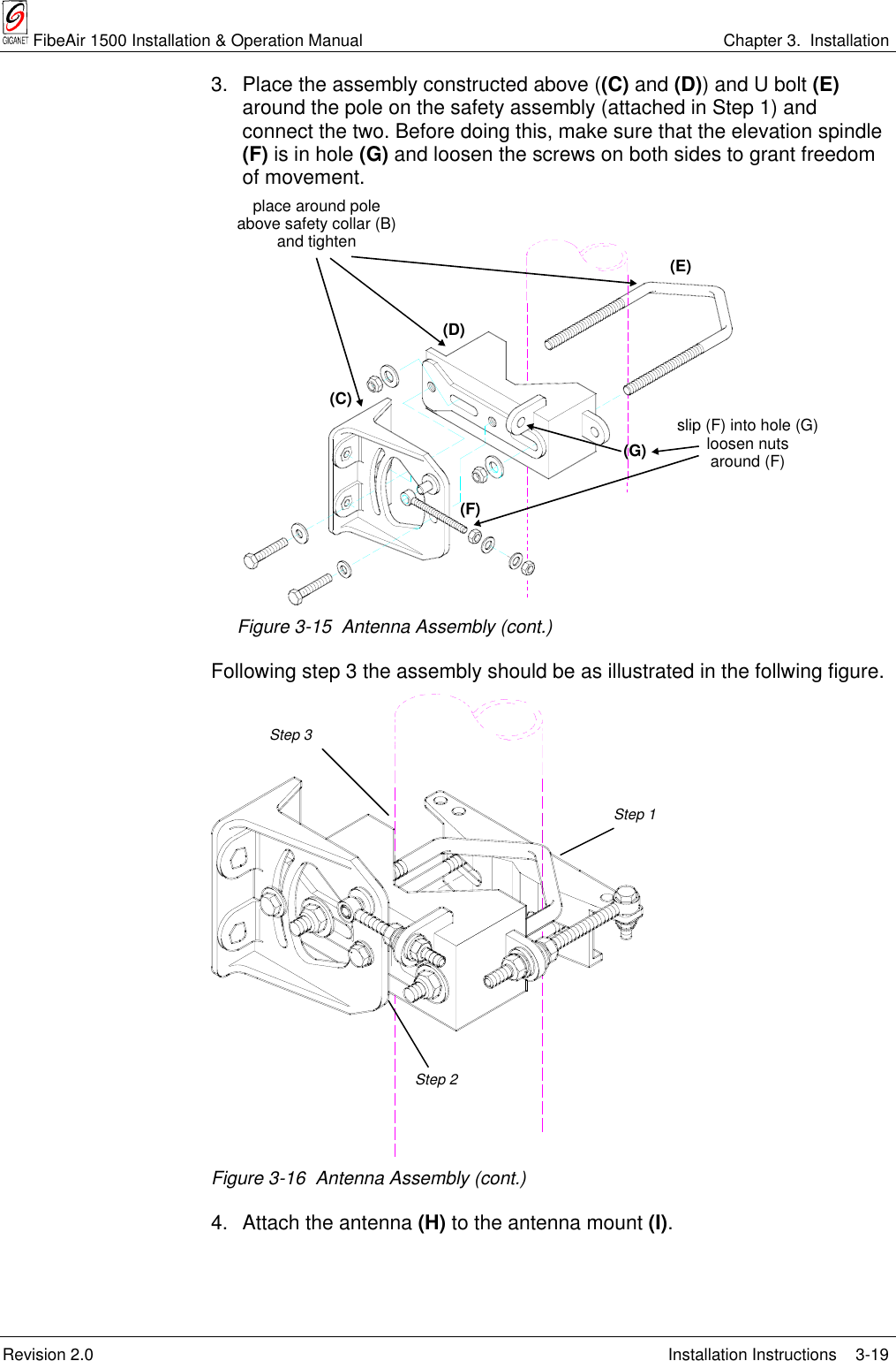
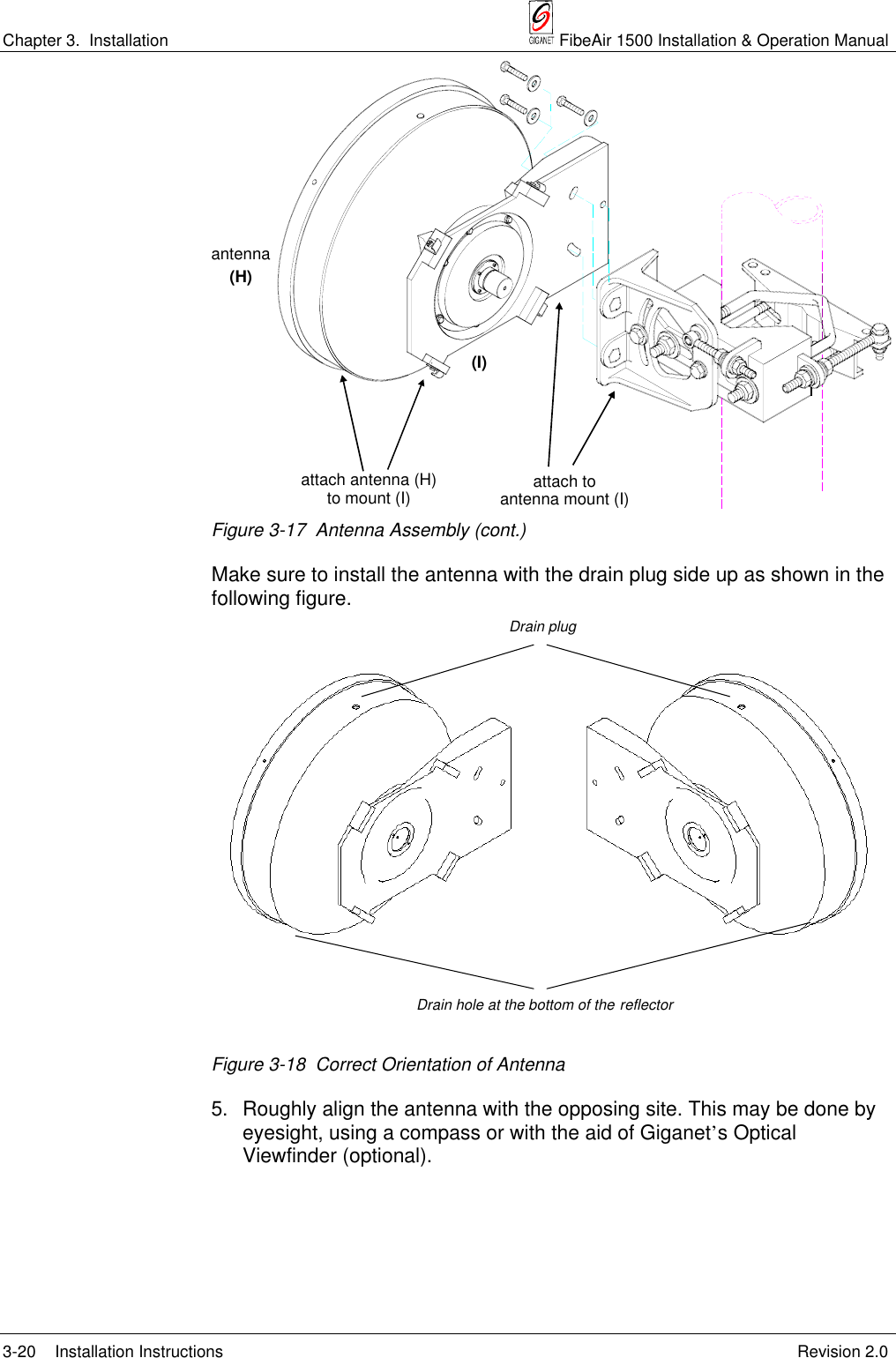
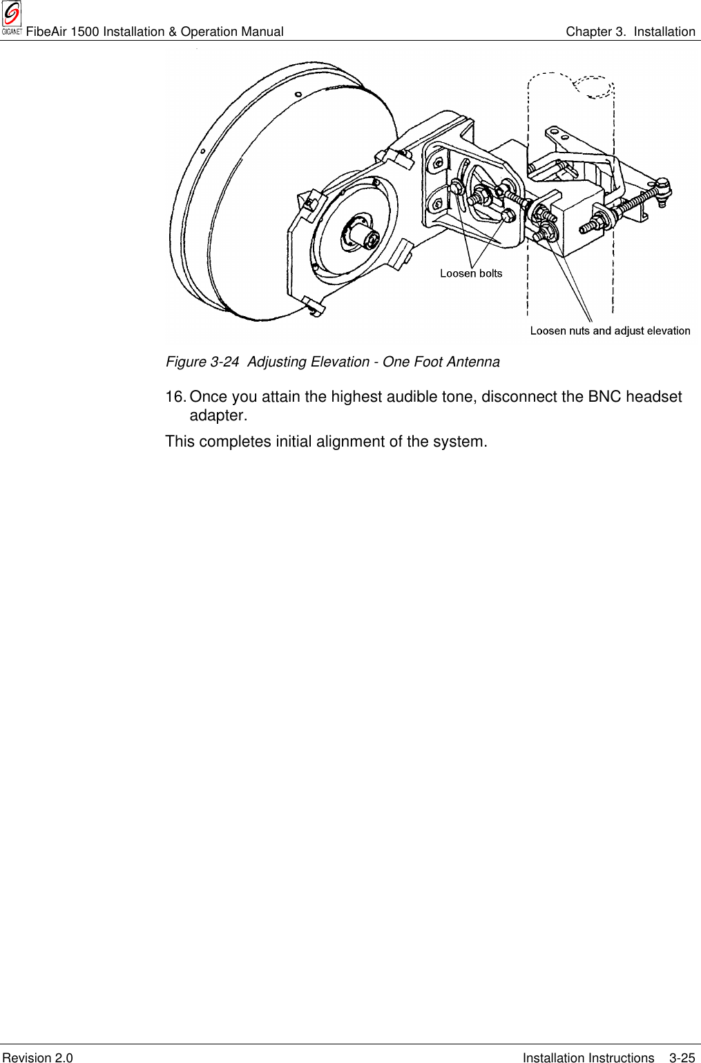
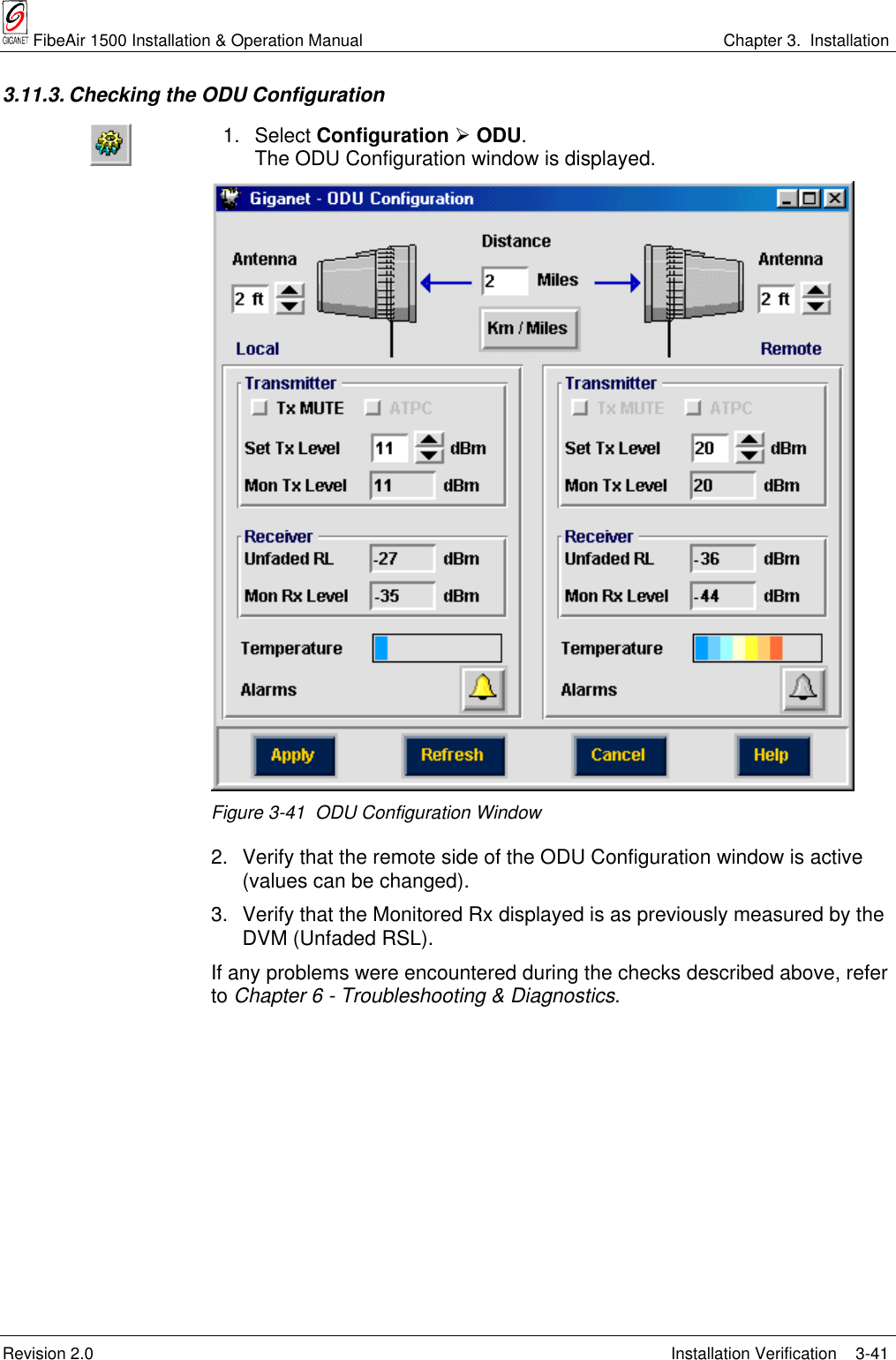
![Chapter 3. Installation FibeAir 1500 Installation & Operation Manual3-4 Suggested Pole Installation Revision 2.03.6. Suggested Pole InstallationThe antenna can be installed on a ground tube, roof, or wall mount. Theground tube or roof/wall mount should be assembled and in place beforeinstalling the antenna mount.Figure 3-1 Calculating Required Pipe DiametersUse the following table to determine the pipe diameters:Table 3-1 Wind LoadingAntenna Size 1 ft. (30 cm) 2 - 21/2 ft.(60 - 75 cm) 4 ft.(120 cm)Minimum Pipe Diameter 50 mm 65 mm 115 mmWind Velocity 200 km/h 200 km/h 200 km/hFAT, max. [N] 303 929 2821FST, max. [N] 150 460 1398MT, max. [Nm] 47 283 894After determining the pole size, verify that you have the required bolt for theantenna mount.Table 3-2 Required Bolt sizePipe Diameter [mm] Bolt size [mm]48 - 51 5152 - 89 8990 - 115 115](https://usermanual.wiki/Ceragon-Networks/GNT-FA1500-28.chapter-3/User-Guide-98648-Page-4.png)