Ceragon Networks GNT-FA1500-28 Point-to-Point digital radio User Manual FibeAir cover
Ceragon Networks Ltd. Point-to-Point digital radio FibeAir cover
Contents
- 1. chapter 4
- 2. chapter 5
- 3. chapter 2
- 4. chapter 3
chapter 3

Revision 2.0 General 3-1
3.1. General
This chapter explains how to install and set up the FibeAir 1500 system. For
best results, perform all operations in the sequence in which they are
presented in this chapter.
3.2. Unpacking Equipment
The FibeAir 1500 is shipped in 5 crates. Upon delivery, make sure that the
following items are included:
■ Two indoor units and accessories
■ Two outdoor units
■ Two antennas and pole mounts
■ One user manual
■ One management software (CD).
Unpack the contents and check for damaged or missing parts. Should there
be any parts that are damaged or missing, contact Giganet’s local
distributor.
3.3. Site Requirements
The first and most important consideration when choosing a prospective site
for the ODU is that the point can provide an acceptable “line of sight” with
the opposing ODU. A site with a clear, unobstructed view is required.
When considering a site, it is important to check for current and future
obstacles. Possible future obstacles are: trees, new buildings, window
cleaners on the roof, snow that may accumulate in front of the antenna, etc.
The site should be accessible to certified personnel only.
As with any type of construction, a local permit may be required before
installing an antenna. It is the owner’s responsibility to obtain any and all
permits.
Chapter 3. Installation FibeAir 1500 Installation & Operation Manual
3-2 Before Installing the ODU Revision 2.0
3.4. Before Installing the ODU
DANGER
WATCH FOR WIRES! Installation of this product near power lines is
dangerous. For your own safety, follow these important safety rules.
■ Perform as many assembly functions as possible on the ground.
■ Watch out for overhead power lines. Check the distance to the power
lines before starting installation.
■ Do not use metal ladders.
■ If you start to drop the antenna or mast assembly, move away from it
and let it fall.
■ If any part of the antenna or mast assembly comes in contact with a
power line, call your local power company. DO NOT TRY TO REMOVE
IT YOURSELF! They will remove it safely.
■ Make sure that the mast assembly is properly grounded.
WARNING!
Assembling antennas on windy days can be dangerous. Because of the
antenna surface, even slight winds create strong forces. Be prepared to
safely handle these forces at unexpected moments. Giganet Ltd. is not
responsible or liable for damage or injury resulting from antenna
installation.
3.5. Required Components and Equipment
3.5.1. Required System Components
The following FibeAir 1500 components are needed to install one radio link:
■ Antenna mount and accessories
■ Antenna
■ ODU
■ Cable
■ Headset
■ BNC headset adaptor
■ BNC DVM adaptor.

FibeAir 1500 Installation & Operation Manual Chapter 3. Installation
Revision 2.0 Required Components and Equipment 3-3
3.5.2. Required Tools
The following tools and equipment are needed to install an ODU:
■ 4 x N-type connectors (according to cable type)
■ Coaxial cable
■ Insulation tape
■ Ratchet wrench (3/8” Drive)
■ 10mm nut driver
■ 13mm socket (3/8” Drive)
■ 13mm open/box end wrench
■ Phillips screwdriver
■ Sharp cutting knife
■ Compass (optional)
■ Torque wrench
■ Digital voltmeter
■ Giganet optical view finder (optional)
3.5.3. Local Management PC Hardware Requirements
Before you install the GiganetView software, verify that your PC has the
minimum requirements as follows:
Processor Pentium (200 MHz minimum)
Memory (RAM) 32 MB minimum
Operating System Windows 95/98/NT
Display Monitor 800 x 600 minimum, 16,384 colors maximum
Keyboard
Mouse
Serial Port RS-232
Chapter 3. Installation FibeAir 1500 Installation & Operation Manual
3-4 Suggested Pole Installation Revision 2.0
3.6. Suggested Pole Installation
The antenna can be installed on a ground tube, roof, or wall mount. The
ground tube or roof/wall mount should be assembled and in place before
installing the antenna mount.
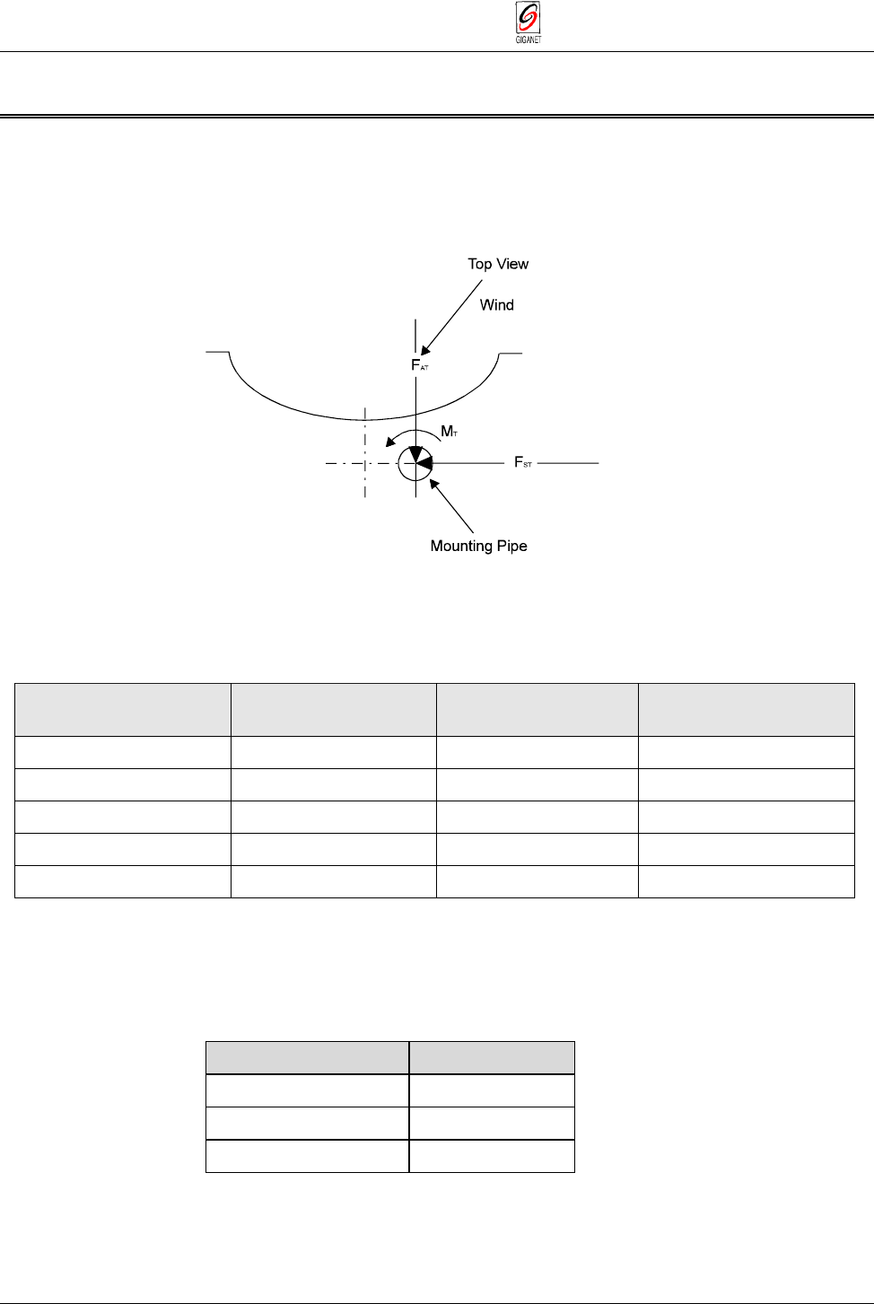
Figure 3-1 Calculating Required Pipe Diameters
Use the following table to determine the pipe diameters:
Table 3-1 Wind Loading
Antenna Size 1 ft. (30 cm) 2 - 21/2 ft.
(60 - 75 cm) 4 ft.(120 cm)
Minimum Pipe Diameter 50 mm 65 mm 115 mm
Wind Velocity 200 km/h 200 km/h 200 km/h
FAT, max. [N] 303 929 2821
FST, max. [N] 150 460 1398
MT, max. [Nm] 47 283 894
After determining the pole size, verify that you have the required bolt for the
antenna mount.
Table 3-2 Required Bolt size
Pipe Diameter [mm] Bolt size [mm]
48 - 51 51
52 - 89 89
90 - 115 115

FibeAir 1500 Installation & Operation Manual Chapter 3. Installation
Revision 2.0 Flow of Operations 3-5
3.7. Flow of Operations
The installation and setup procedure for the FibeAir 1500 consists of the
following operations (to be performed in the order listed below):
GiganetView Management Software:
■ Installing the Management Software
■ Installing a PPP/SLIP Driver
■ Setting the Baud Rate
IDU:
■ Installing the IDU
■ Turning IDU On
■ Connecting to a PPP/SLIP or Ethernet Port
■ Setting the IP addresses
■ Setting Local Tx Frequency Channel
■ Activating Engineering Order Wire (EOW)
■ Setting Antenna Diameter and Distance
■ Determining the Expected Signal Level
ODU:
■ Installing the antenna assembly
— Azimuth adjustment
— Elevation adjustment
■ Initial antenna alignment − using a compass, Giganet’s optical view
finder and headset.
■ Alignment − checking actual receive level
■ Performing an Initial Check
■ Verifying Installation.
Chapter 3. Installation FibeAir 1500 Installation & Operation Manual
3-6 Installing the IDU - Rack Mount Assembly Revision 2.0
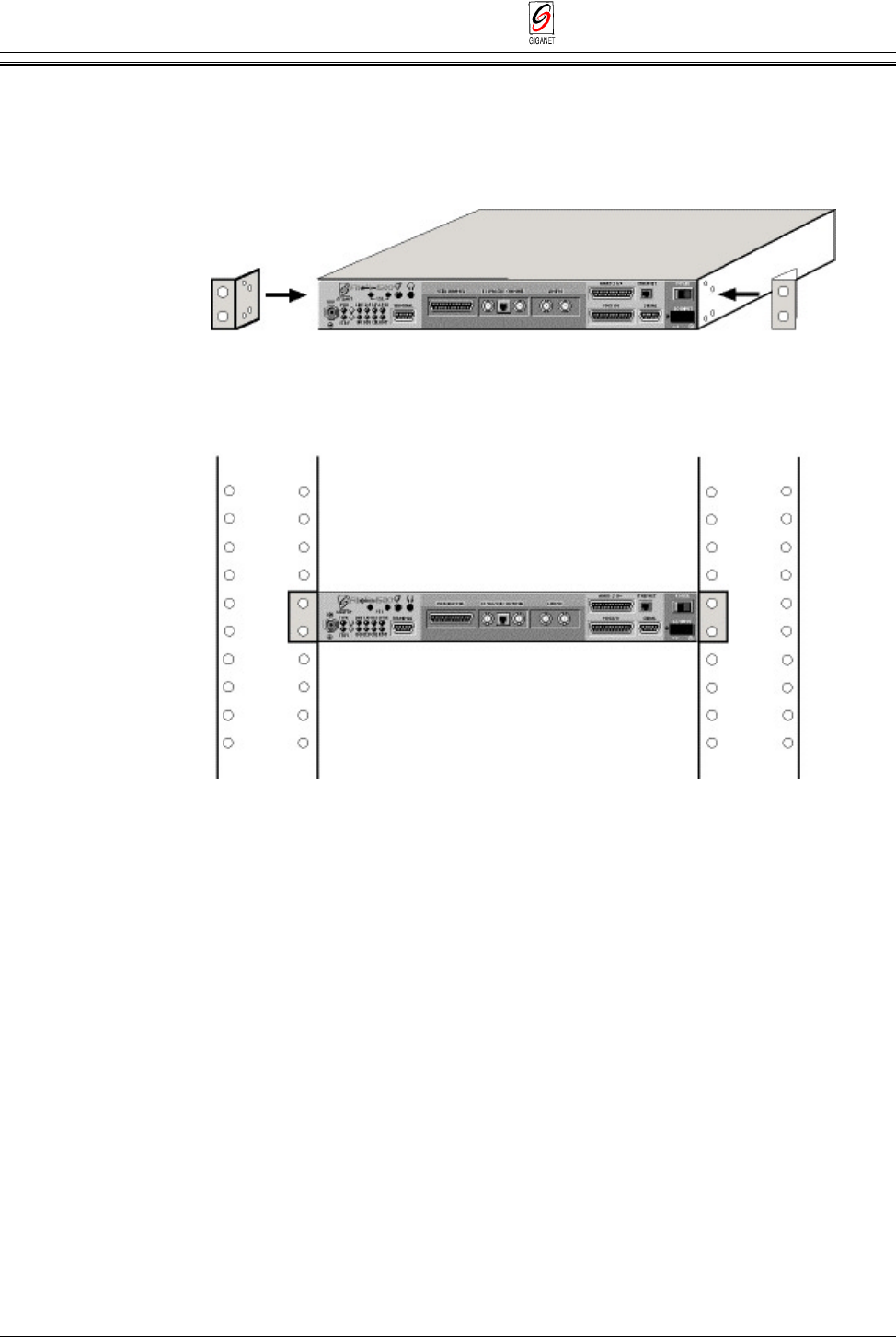
3.8. Installing the IDU - Rack Mount Assembly
The IDU may be installed in a 19" rack (1U) using the rack mount kit. The
mount braces are attached to each side of the IDU using the three holes on
each side. To attach the rack mount to the IDU follow these steps:
Figure 3-2 Rack Mount Assembly
1. Attach mount braces to each side of the IDU, and using the screws
supplied attach them to the holes in the IDU side panel (see illustration).
2. Install the IDU unit in the 19” rack as shown in the lower part of the
illustration.
3. To power on the unit, connect the WV-0001-0 cable supplied to the DC
Input interface on the front of the IDU and connect the other side of the
cable to the DC voltage supply:
White – GND
Green – +48v
Brown – 0v
4. When more than one unit is installed, it is recommended to keep a gap
of 1U between the units in the rack.
FibeAir 1500 Installation & Operation Manual Chapter 3. Installation
Revision 2.0 Installation Instructions 3-7
3.9. Installation Instructions
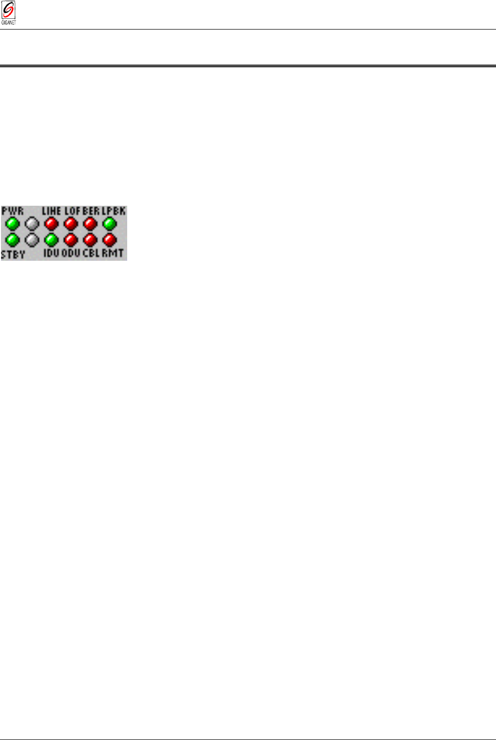
3.9.1. IDU Power On
1. Turn the IDU power switch to ON.
The LED display should appear as described below:
LED Color Explanation
PWR Green Power on
STBY Green Normal operation
LINE Red No input to main channel/High Ber
IDU Green IDU operating and no IDU alarm
LOF Red Loss of Frame detected (no radio connection)
ODU Red No communications to ODU
BER Red Excessive bit error rate detected
CBL Red RF cable open/short
LBK Green Loopback not operated
RMT Red Remote unit not connected.
If the LED display is not as described above, refer to
Chapter 6 -
Troubleshooting & Diagnostics
.
3.9.2. IDU Initialization
The IDU initialization and basic configuration is made via the Terminal
interface on the IDU front panel using the standard Windows HyperTerminal
at 19200 bits per second. The basic configuration includes setting IP
addresses for the Ethernet and serial ports. These are needed for running
the Gigaview software.
The system configuration can be completed either by using the
HyperTerminal or by using the Gigaview application. The recommended
way to start is by running the Quick Setup Procedure using the
HyperTerminal as described in section 4.2.3, and continues to install the
Gigaview software.
3.9.3. Setting IP addresses for the Ethernet and serial ports
Refer to
Chapter 4. System Setup
, paragraph
4.2.1. Setting IP addresses
for the Ethernet and serial ports
.
For general guidance concerning network management configuration, refer
to Appendix D.
Chapter 3. Installation FibeAir 1500 Installation & Operation Manual
3-8 Installation Instructions Revision 2.0
3.9.4. Installing the GiganetView Management Software
1. Insert the “GiganetView” CD into your CD drive.
2. Via Windows Explorer or the File Manager, double-click on the
“setup.exe” file.
The installation program begins installation.
3. Follow the instructions displayed.
The full installation procedures are included in the Appendix A.
Note
The recommended resolution is 1024 x 768.
3.9.5. Connecting to the Ethernet Port
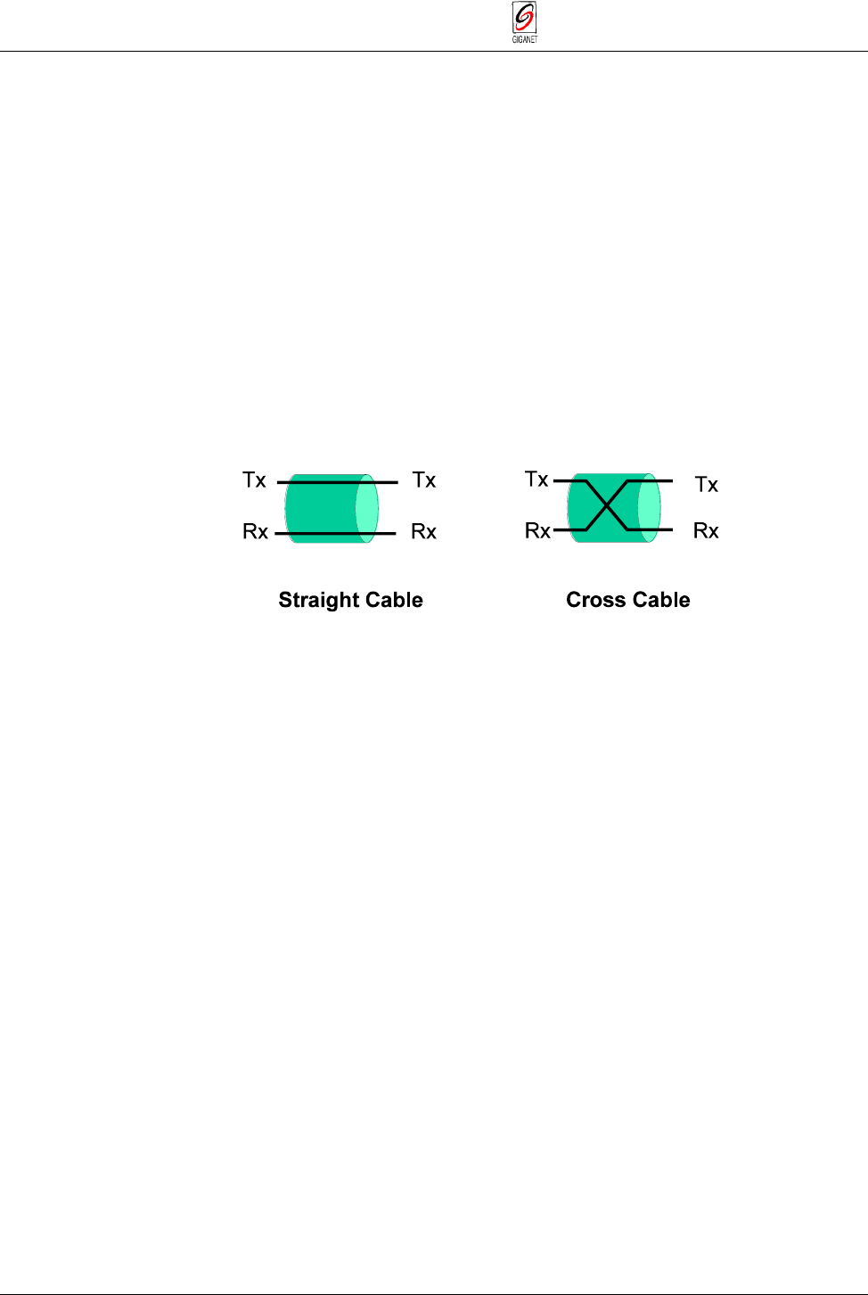
1. Connect a crossed Ethernet cable from your PC to the Ethernet Port. If
the connection is to a LAN (wall connection) use the standard Ethernet
cable.
Figure 3-3 Crossed and Straight Cable
2. Make sure the IP address on your PC is on the same sub-net as you
defined in the FibeAir indoor unit (i.e. in most cases, the first three
numbers of the IP address must be identical, depending on the sub-net
mask).
3. Run the GiganetView software from your computer.
3.9.6. Connecting to a PPP/SLIP Port
Remove the IDU cable from the TERMINAL port and connect it to the
SERIAL port (RS-232).
3.9.7. Installing a PPP/SLIP Driver
Install a PPP/SLIP driver in your computer. Refer to Appendix A for details
of installation in Windows 95 and NT.
The installation of the PPP/SLIP driver is needed only for the first time that
you operate the computer.
FibeAir 1500 Installation & Operation Manual Chapter 3. Installation
Revision 2.0 Installation Instructions 3-9
3.9.8. Setting the Baud Rate (for serial connections)
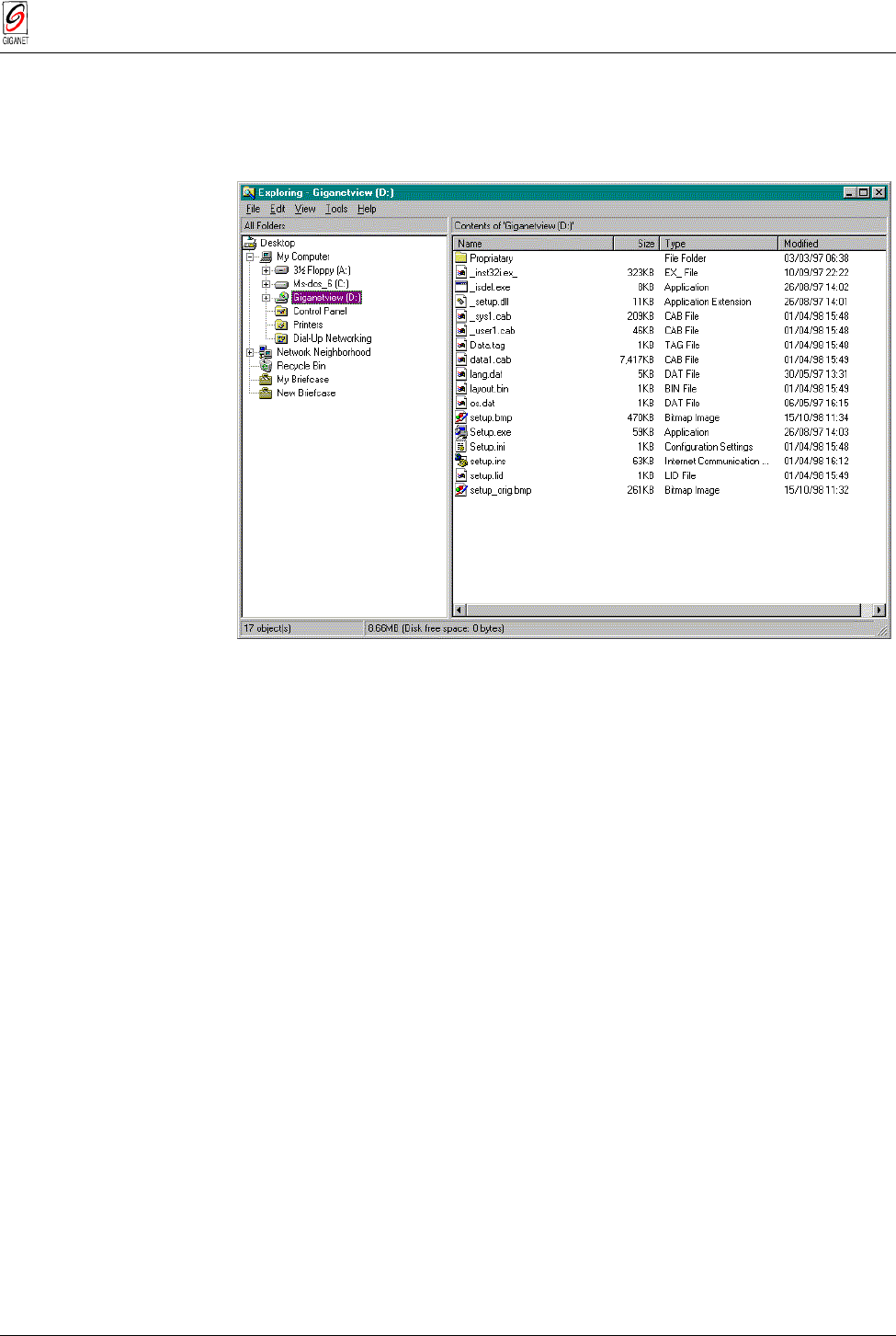
1. Double-click on the My Computer icon of the Windows Program
Manager. My Computer window is displayed.
Figure 3-4 The My Computer Window
2. Double-click on Dial-Up Networking.
The Dial-Up Networking window is displayed.
3. On the icon, which was added after performing the steps detailed in
Appendix A. SLIP Driver Installation
, click the right mouse button and
select the Properties option.
The Properties window is displayed.
4. In the Connect Using section of the Properties window, click on Direct
Connection and click on the Configure push-button.
The Configure window is displayed.
5. Select the General tab.
The General window is displayed.
6. Set the Maximum Speed to 19,200.
7. Click OK.
The Configure window is closed.
Chapter 3. Installation FibeAir 1500 Installation & Operation Manual
3-10 Installation Instructions Revision 2.0
3.9.9. Connecting to the IDU using the serial port
1. Double-click on the icon which was added after performing the steps
detailed in Appendix A (My Computer½Dial-up Networking).
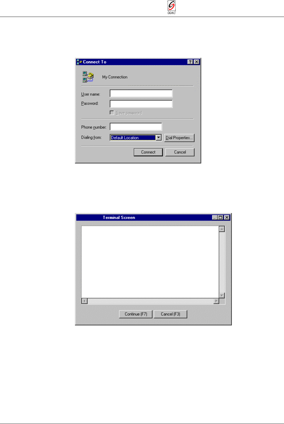
The Connect To window is displayed.
Figure 3-5 The Connect To Window
Note
At this time, there is no importance to the values of fields in the Connect To window.
2. Click Connect.
The Terminal window is displayed.
Figure 3- 6 The Terminal Screen Window
3. Click Continue.
The Connected To window is displayed.
4. Select Start ½ Program ½ GiganetView.
The RunEnv Parameters window is displayed.
FibeAir 1500 Installation & Operation Manual Chapter 3. Installation
Revision 2.0 Installation Instructions 3-11
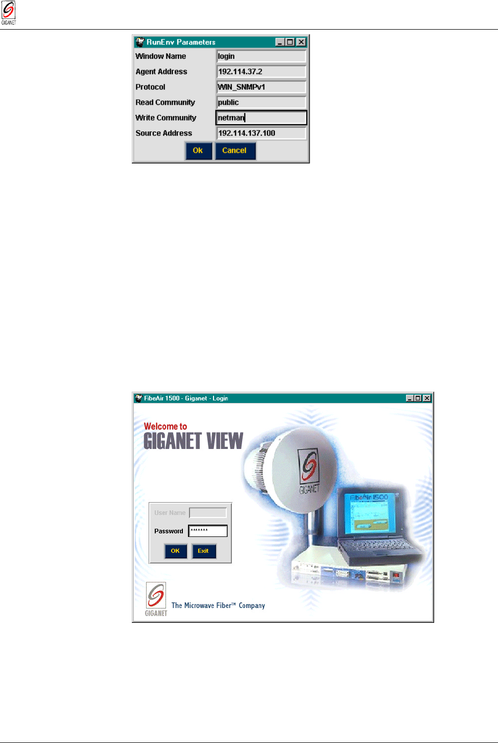
Figure 3-7 RunEnv Paramaters Window
5. In the RunEnv Parameters window, leave the
Window Name
field
unchanged.
6. In the
Agent Address
field, enter the IP address of the FibeAir 1500
serial port.
7. Leave the
Protocol
field unchanged.
8. In the
Read Community
field, enter the Read community.
The default value is public.
9. In the
Write Community
field, enter the Write community.
The default value is netman.
10. Leave the
Source Address
field unchanged.
11.Click OK.
The Login window is displayed.
Figure 3-8 Login Window
12. To log in, enter your password and click OK.
By default, your read/write password is giganet.
After logging in, the Work Area and Physical View windows are
displayed (see Chapter 5 for details).
Chapter 3. Installation FibeAir 1500 Installation & Operation Manual
3-12 Installation Instructions Revision 2.0
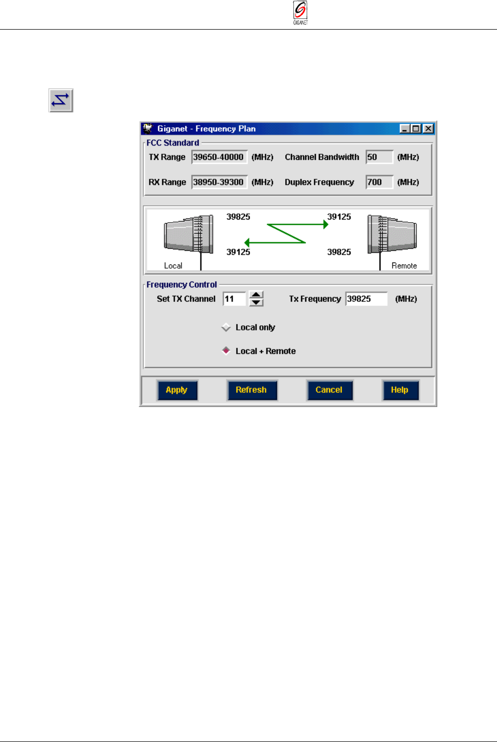
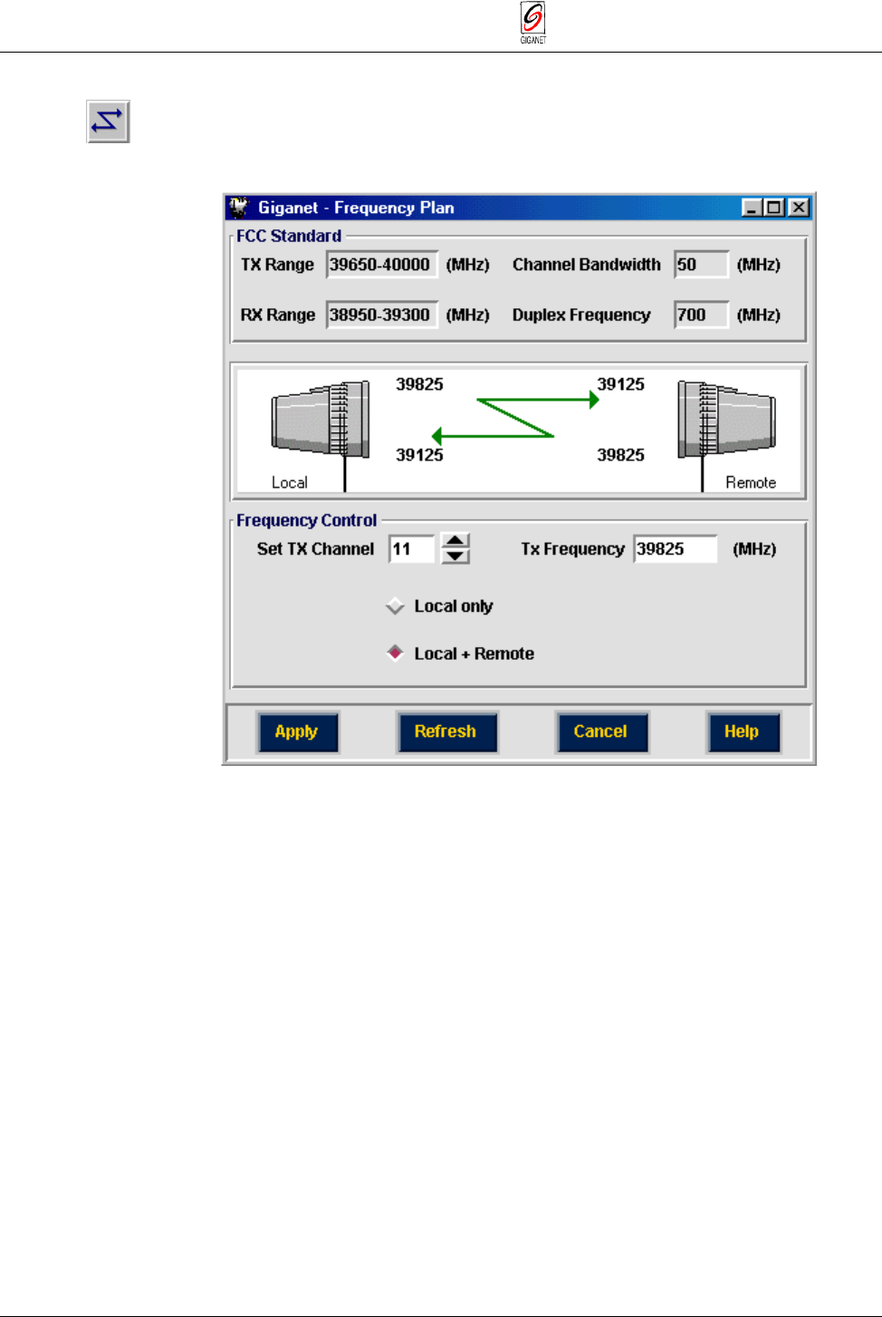
3.9.10. Setting Local Tx Frequency Channel
If the Tx frequency was previously defined using the Hyperterminal, use this
screen only to verify that the correct frequency was set.
1. Select Configuration ½ Set frequency.
The Frequency Plan window is displayed.
Figure 3-9 Frequency Plan Window
At the top of the window, the system displays Tx/Rx ranges, the gap
between them according to the appropriate standard (FCC or ETSI) and the
channel bandwidth.
2. In the Frequency Control section, set the Tx Channel to the required
channel. By default it is set to the first channel. If you are unsure of the
required channel, refer to Appendix E for FCC or ETSI channel
allocations.
The frequency of the selected Tx channel appears in the Tx Frequency
field.
3. If you prefer, you may set the Tx frequency by entering a frequency in
MHz In the Tx Frequency section. If a channel is available for this
frequency, it will appear in the Set Tx Channel field. If not, a warning
message appears to enable the entered frequency or to change it to the
next available channel.
4. Select the Local Only option (radio button should be filled ♦).
By default, the Local + Remote option is selected.
However, since there is no connection to the remote unit at this time, the
Local + Remote option is not available.
FibeAir 1500 Installation & Operation Manual Chapter 3. Installation
Revision 2.0 Installation Instructions 3-13
5. Click Apply.
The settings are saved in the IDU configuration. From this point on, the
ODU is set to the desired frequency.
6. Click Cancel to close the window.
The Frequency Plan window is closed and you are returned to the Work
Area window.
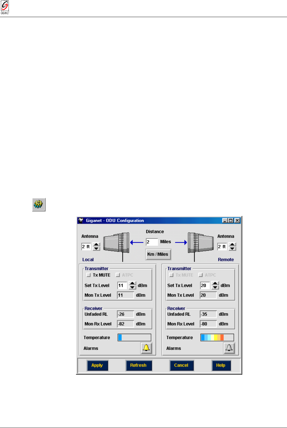
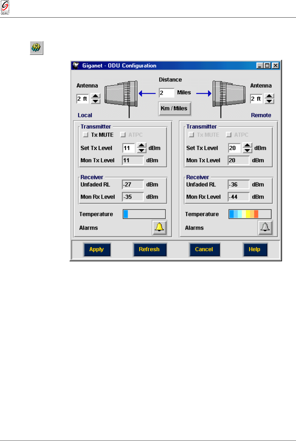
3.9.11. Setting Transmitted Power, Antenna Diameter and Operating Distance
If the Tx power level was previously defined using the HyperTerminal, use
this screen only to verify that the correct power was set.
You can perform the following in the ODU configuration window:
■ Set transmitter power levels or mute it.
■ View the current received level (RSL).
■ Set antenna size and link distance to determine the expected RSL (in
RSL graph and radio performance monitoring window).
■ View ODU temperature graph.
After setting the link, you can set the parameters in ODU configuration
window, for both local and remote ODU’s.
1. Select Configuration ½ ODU.
The ODU Configuration window is displayed.
Figure 3-10 ODU Configuration window

Chapter 3. Installation FibeAir 1500 Installation & Operation Manual
3-14 Installation Instructions Revision 2.0
Note
Since there is no connection with the remote terminal, you can change only Local Unit
parameters at this stage.
2. In the top of the window, select the diameter of the Local Antenna from
the drop-down list (1, 2, 3, 4, or 6 foot). The default value is 1 foot.
3. In the top center of the window, select the distance using the
buttons.
4. In the top right of the window, select the diameter of the Remote
Antenna from the Antenna drop-down list (1, 2, 4, or 6 ft.).
5. In the Transmitter section, set Tx Level of the Local Unit to the maximum
allowed Tx level to facilitate the alignment process.
Note that the Transmit Level should be adjusted following antenna
alignment (see Chapter 4 for details).
6. In the Transmitter section, set Tx Level of the Remote Antenna to the
maximum setting to facilitate the alignment process.
7. Click Apply.
8. Make a note of the expected signal level displayed in the Unfaded RL
field.
For example, in the window shown above the expected value is
-35
dBm for the remote side and
–
26dBm for the local receiver.
9. Click Cancel.
The ODU Configuration window is closed and you are returned to the
Work Area window.
3.9.12. Exiting GiganetView Management Software
1. In the Work Area window, select File ½ Exit to exit the Management
software.
The Work Area and Physical Area and Physical View windows are
closed.
2. Turn off the IDU.
The following sections describe the installation procedures for 1 foot and 2
foot antennas which are the most frequently used. For procedures on
installing other antennas, see the Antenna Information appendix.
FibeAir 1500 Installation & Operation Manual Chapter 3. Installation
Revision 2.0 Installation Instructions 3-15
3.9.13. Installing a One Foot Antenna Assembly
For site requirements and pole installation, refer to sections 3.3 and 3.6.
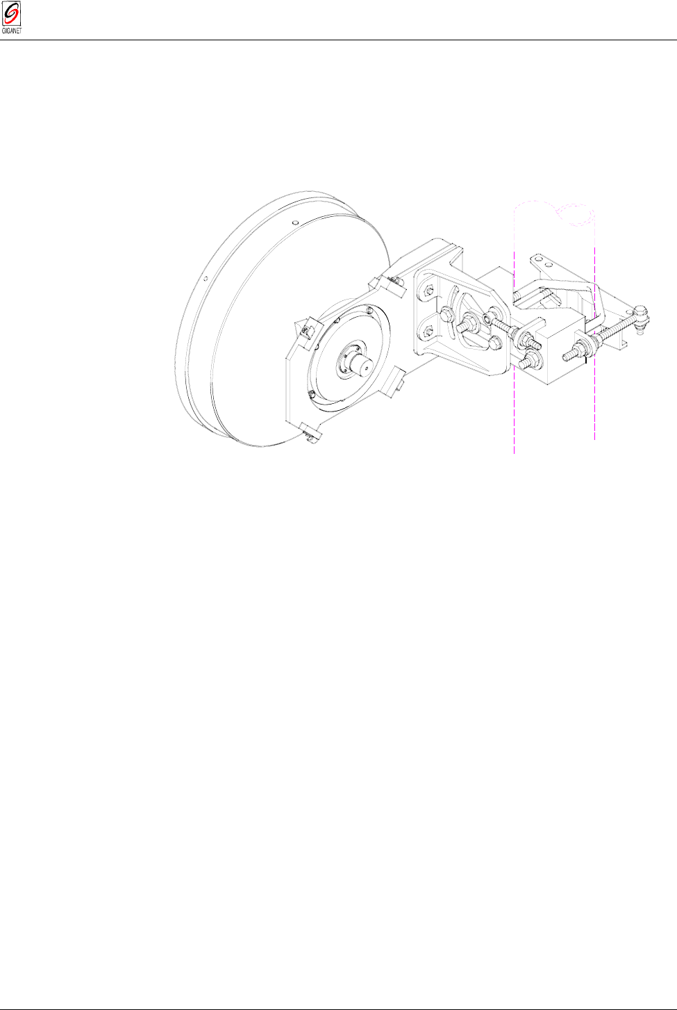
3.9.13.1. General
The following figure shows a one foot antenna mounted on a pole.
Figure 3-11 A Mounted One Foot Antenna
Chapter 3. Installation FibeAir 1500 Installation & Operation Manual
3-16 Installation Instructions Revision 2.0
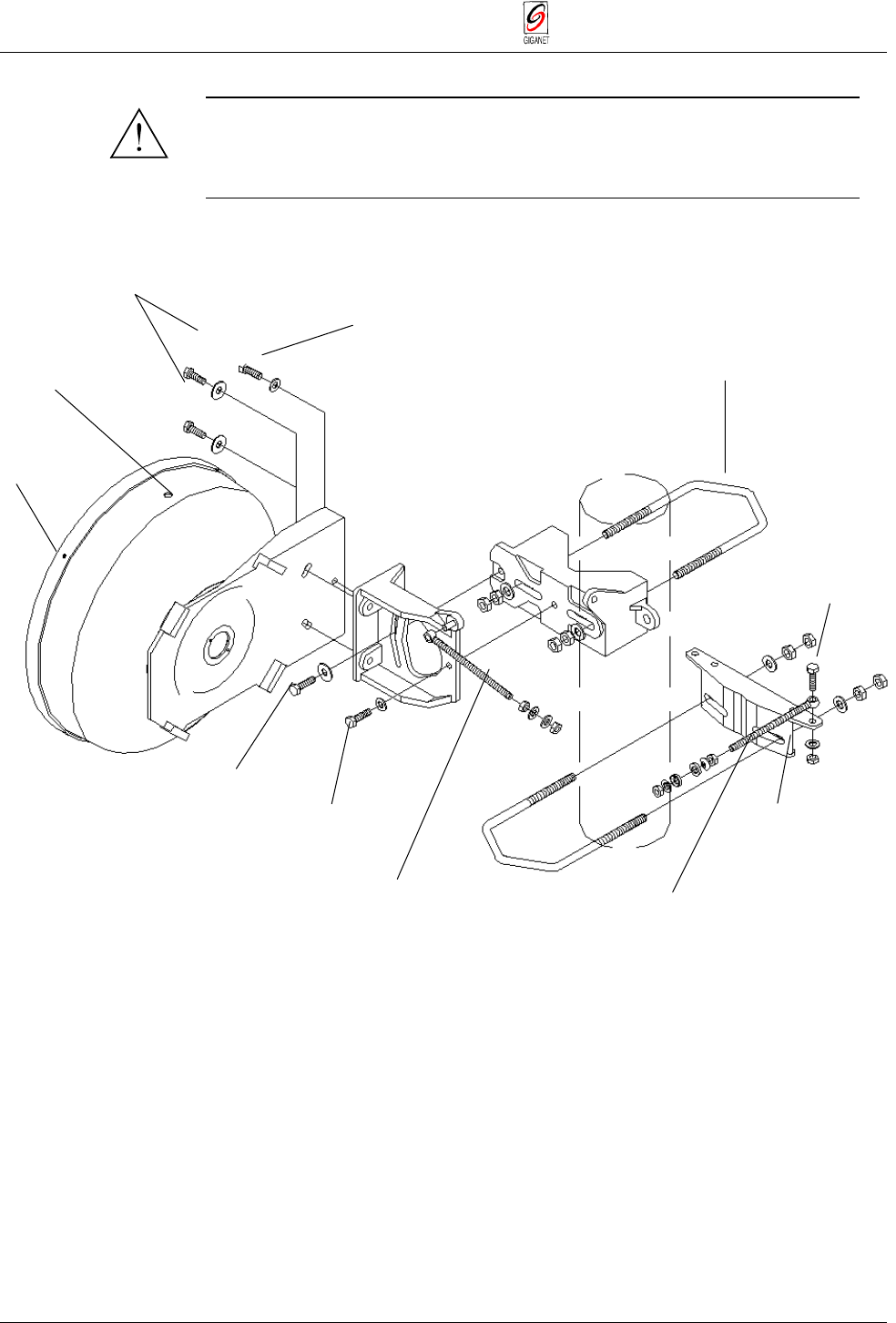
3.9.13.2. One Foot Antenna Assembly − Installation Instruction
Warning
It is important to mount the antenna exactly as described in this
installation instruction. Giganet disclaims any responsibility for the result
of improper or unsafe installation. These installation instructions have
been written for qualified, skilled personnel.
Refer to the following figure, while performing the installation instructions
given.
Figure 3-12 Antenna Assembly - One Foot Antenna
4 screws B4.2
Drain plug
2 bolts M8 x 25
2 washers 8.4
∅
25
Bolt M8 x 25 U bolt M10
2 washers 10.5
∅
30
4 nuts M10
Bolt M8 x 30
Bolt M8 x 30
ELEVATION
spindle M8 x 145
2 brass nuts M8
2 washers 8.4 AZIMUTH spindle M8 x 145
*
2 brass nuts M8
2 spherical washers C 8.4
2 conical seats D 9.6
Safety collar *
U bolt M10
2 washers 10.5
∅
30
4 nuts M10
Bolt M8 x 30
Washer 8.4
SL nut M8
* safety collar and azimuth spindle
(on request)
FibeAir 1500 Installation & Operation Manual Chapter 3. Installation
Revision 2.0 Installation Instructions 3-17
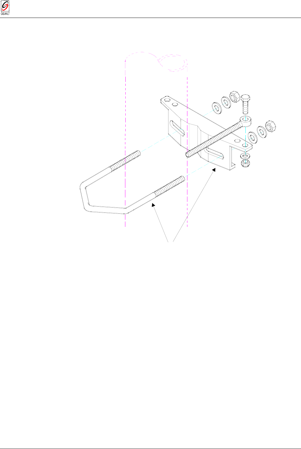
1. Place U bolt (A) and safety collar (B) around the pole at the desired
height, connect them and tighten in place at a 90° angle to the opposing
site direction.
Place around pole
desired height
a
n
d
t
i
g
h
t
e
n
(A)
(B)
Safety collar
Ubolt
Figure 3-13 Antenna Assembly (cont.)
Note
The safety collar assembly shown in Figure 3-14 above ((A) and (B)) is used to align
and support the antenna mount during installation and antenna alignment. Once the
mount is in place and alignment is completed, all bolted joints of the antenna mount are
tightened and there is no further need for the support provided by the safety collar
assembly. It may then be removed for use in future installations.
Chapter 3. Installation FibeAir 1500 Installation & Operation Manual
3-18 Installation Instructions Revision 2.0
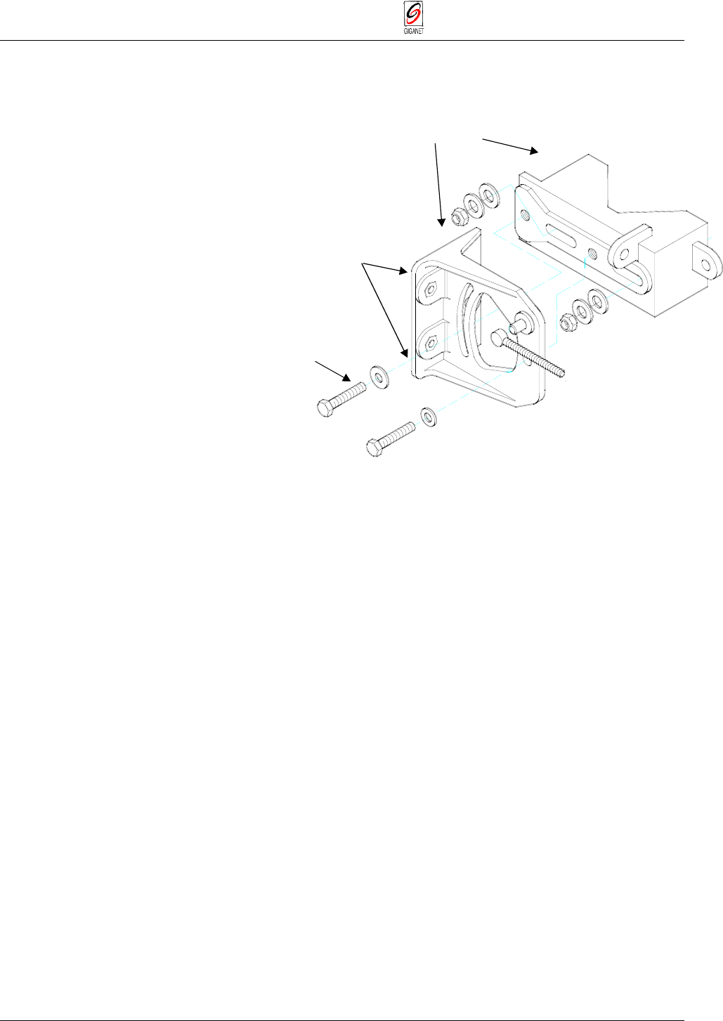
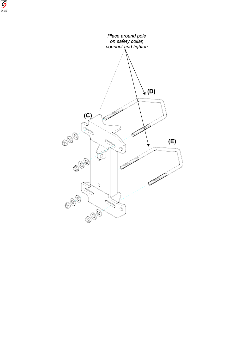
2. Connect (C) to (D) at the approximate elevation needed to face the
opposing ODU (determined by the bolts fastened to part (C)).
(C)
(D)
C
o
n
n
e
c
t
(
C
)
t
o
(
D
)
Set angle before tightening
bolts to determine elevation
Tighten after desired
elevation angle is set
Figure 3-14 Antenna Assembly (cont.)
FibeAir 1500 Installation & Operation Manual Chapter 3. Installation
Revision 2.0 Installation Instructions 3-19
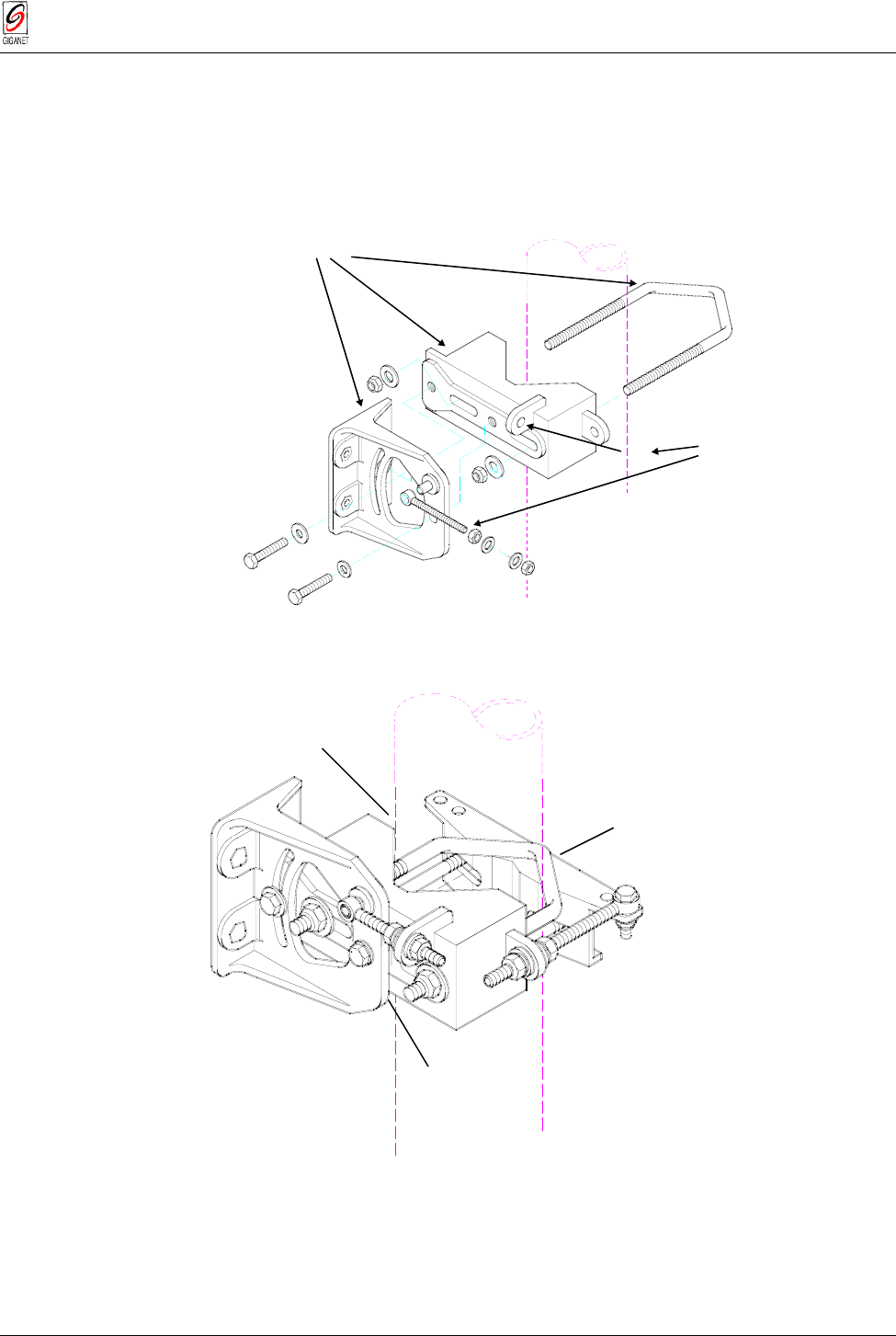
3. Place the assembly constructed above ((C) and (D)) and U bolt (E)
around the pole on the safety assembly (attached in Step 1) and
connect the two. Before doing this, make sure that the elevation spindle
(F) is in hole (G) and loosen the screws on both sides to grant freedom
of movement.
place around pole
above safety collar (B)
and tighten
slip (F) into hole (G)
loosen nuts
around (F)
(C)
(D)
(F)
(E)
(G)
Figure 3-15 Antenna Assembly (cont.)
Following step 3 the assembly should be as illustrated in the follwing figure.
Figure 3-16 Antenna Assembly (cont.)
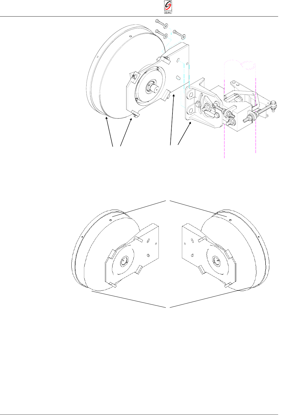
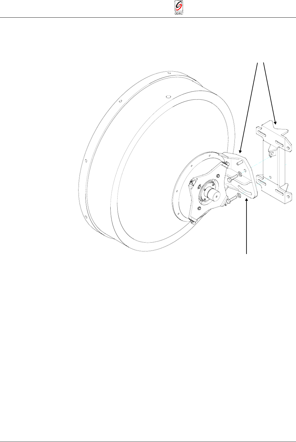
4. Attach the antenna (H) to the antenna mount (I).
Step 1
Step
2
Step
3
Chapter 3. Installation FibeAir 1500 Installation & Operation Manual
3-20 Installation Instructions Revision 2.0
attach antenna (H)
to mount (I) attach to
antenna mount (I)
(I)
(H)
antenna
Figure 3-17 Antenna Assembly (cont.)
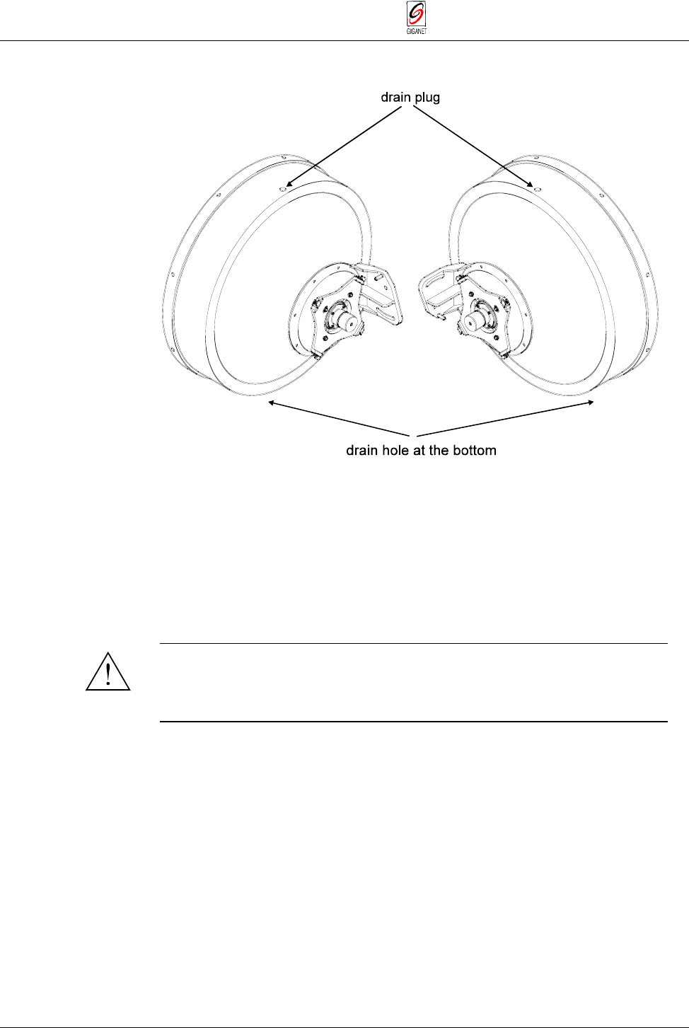
Make sure to install the antenna with the drain plug side up as shown in the
following figure.
Figure 3-18 Correct Orientation of Antenna
5. Roughly align the antenna with the opposing site. This may be done by
eyesight, using a compass or with the aid of Giganet’s Optical
Viewfinder (optional).
Drain plug
Drain hole at the bottom of the
reflector
FibeAir 1500 Installation & Operation Manual Chapter 3. Installation
Revision 2.0 Installation Instructions 3-21
Tip
It is sometimes difficult to identify the opposing site. For this reason, it is sometimes
helpful to have someone at the opposing site use a reflecting device, such as a hand-held
mirror, to reflect sunshine towards you. The Giganet optical viewfinder can help in
initial antenna alignment.
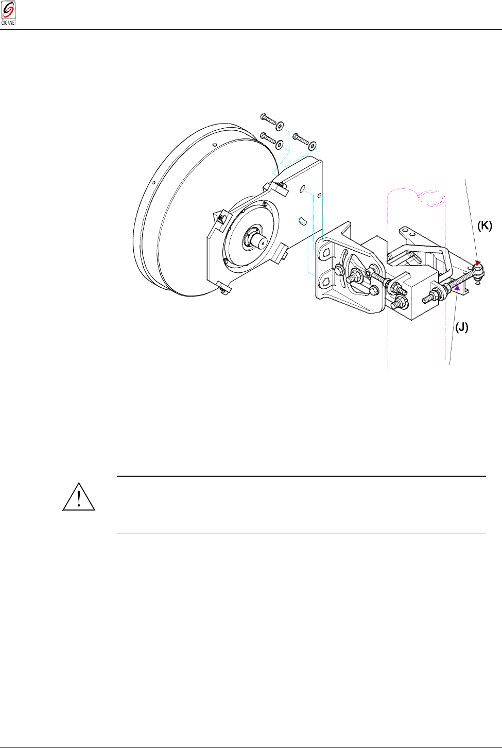
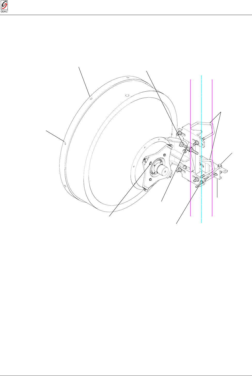
6. Insert the azimuth spindle (J) into hole (K) and tighten in place.
Bolts M8 x 3
0
Washers 8.4
Sl nuts M8
Azimuth spindle M8 x 14
5
Figure 3-19 Antenna Assembly (cont.)
7. Mount Giganet optical viewfinder on the antenna (optional). Locate the
opposite site through the viewfinder and loosely tighten the bolts.
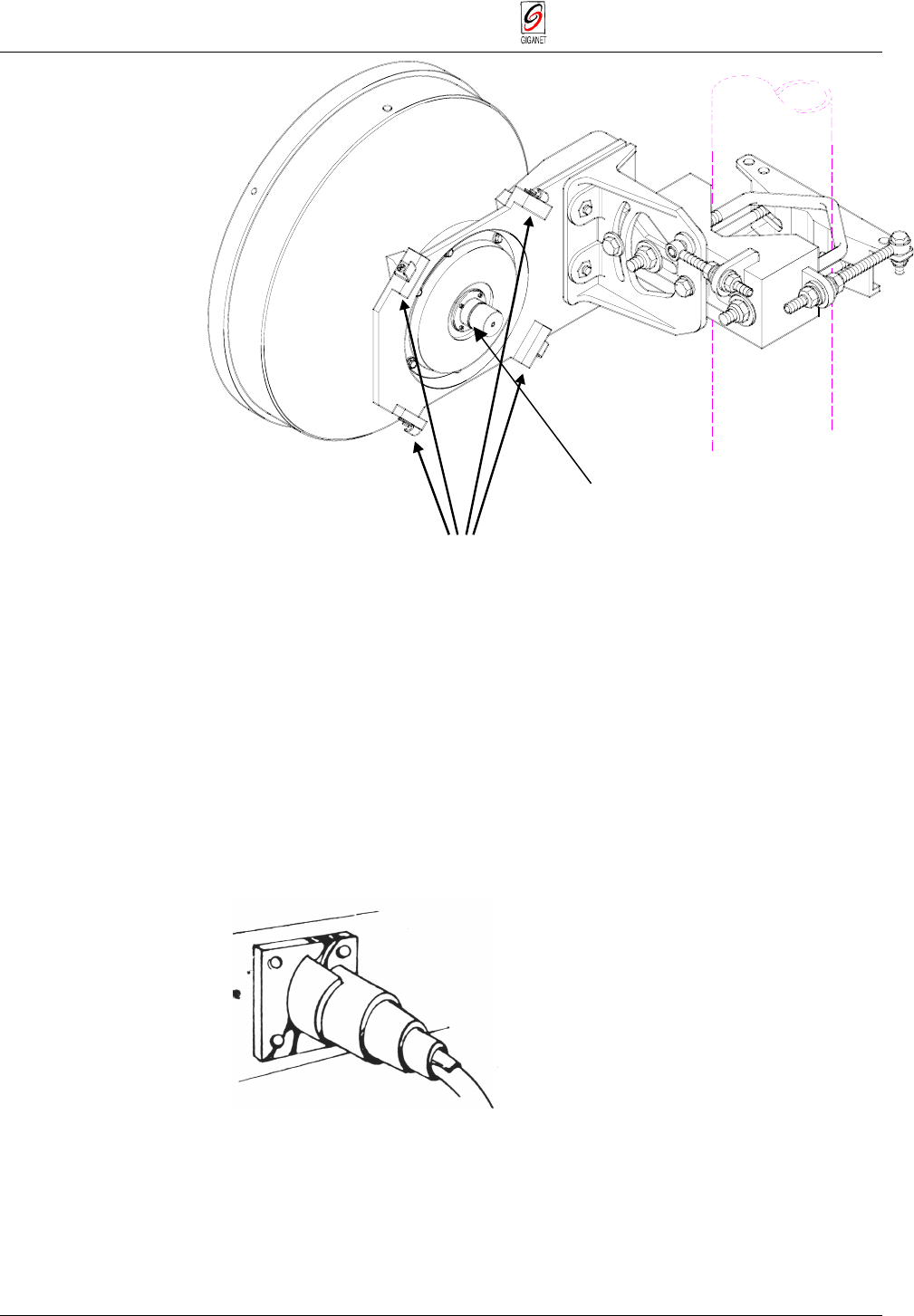
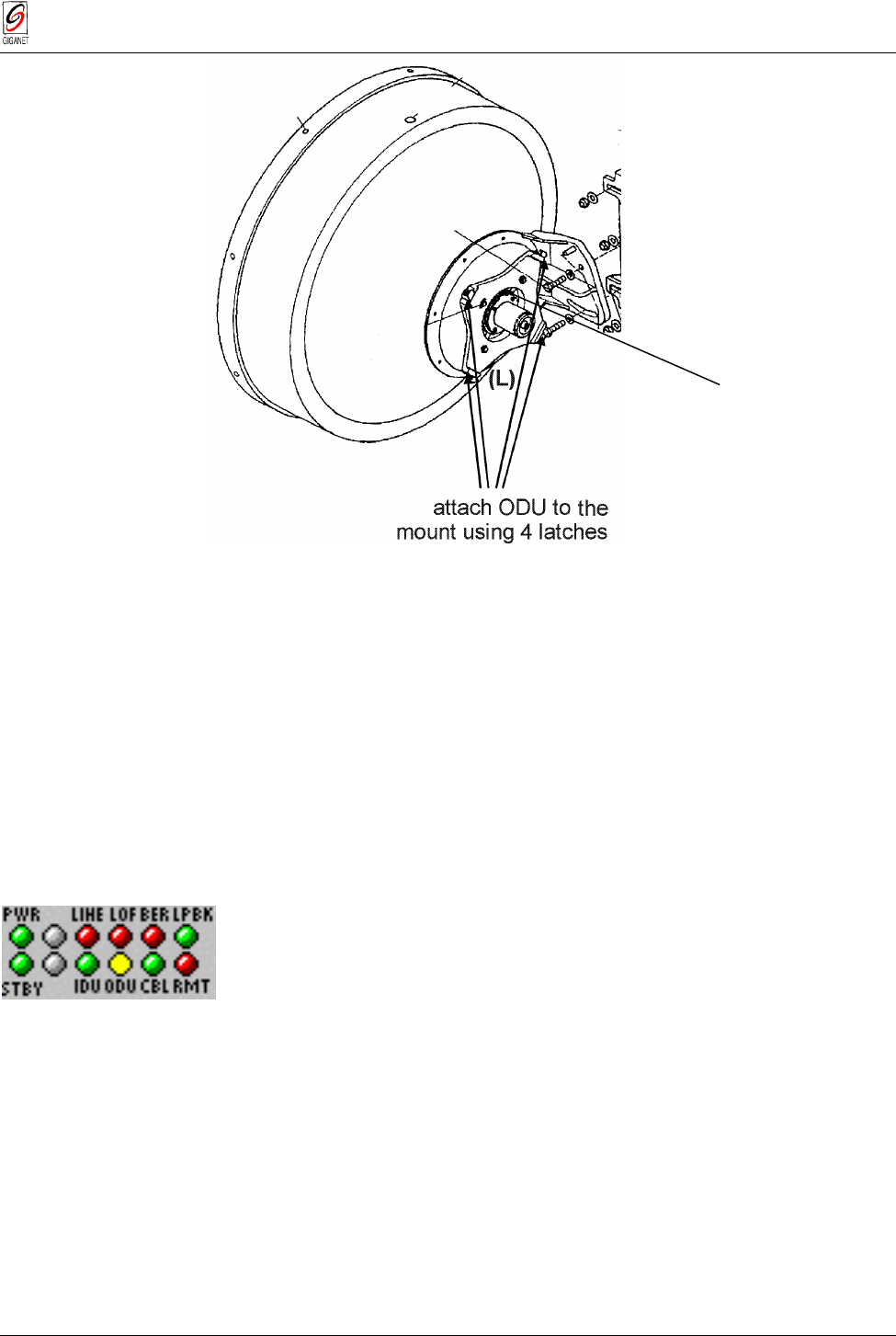
8. Attach the ODU to the mount assembly using the four latches on the
ODU (L). See the following figure.
Warning
To verify proper sealing, confirm existence of a rubber O-ring on the
antenna, as shown in the following figure.
Setting Polarization
Polarization is determined by the orientation of the ODU. If the handle of the
ODU is facing up or down then the polarity is vertical. If the handle of the
ODU is to the side then the polarization is horizontal.
Tip
For easy installation and best weather immunity, mount the ODU so that the connectors
are facing down.
Chapter 3. Installation FibeAir 1500 Installation & Operation Manual
3-22 Installation Instructions Revision 2.0
attach ODU to
mount usin
g
4 latch
e
s
(L)
Figure 3-20 Antenna Assembly (cont.)
9. Connect the coaxial cable between the IDU and ODU using the
N-Type connector on the IDU and the ODU.
10. Make sure that the fittings and the coax cable are clean and dry.
11. Peel approximately 6 inches of COAX-SEAL from the paper backing.
12. Wrap isolation tape over the coax cover. Start winding from coax cover
towards fitting with one half overlap with each winding making sure all
joints are well covered.
Figure 3-21 Steps 1, 2 & 3
13. After entire fitting and coax cable are covered with approximately 3/16"
thick layers, mold and form COAX-SEAL with fingers to make a smooth
surface and force out any air.
Rubber O-ring
FibeAir 1500 Installation & Operation Manual Chapter 3. Installation
Revision 2.0 Installation Instructions 3-23
Figure 3- 22 Step 4
14. If more COAX-SEAL is necessary to complete seal, simply cut the
needed amount and add to existing COAX-SEAL, molding and press into
the other material. COAX-SEAL adheres to itself with slight pressure.
Carefully inspect seal to make certain that all joints are covered
Tip
Connect and disconnect the IDU from the ODU only when power is off.
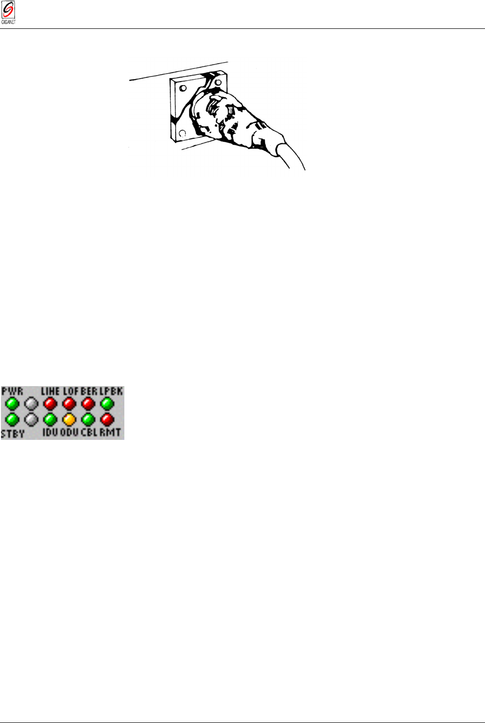
15. Turn the IDU power switch to ON.
The LED display should appear as described below to indicate normal
operation of the FibeAir 1500.
LED Color Explanation
PWR Green Power on
STBY Green Normal operation
LINE Red No input to main channel/High Ber
IDU Green IDU operating and no IDU alarm
LOF Red Loss of Frame detected (no radio connection)
ODU Yellow Rx/Tx out of range
BER Red Excessive bit errors detected
CBL Green Cable between IDU and ODU properly connected
LBK Green Loopback not operated
RMT Red Remote unit not connected
If the LED display is not as described above, refer to
Chapter 6. Troubleshooting & Diagnostics
.
3.9.14. Initial Antenna Alignment
−
Using the Headset
■ Connect the headset BNC adapter to the ODU.
■ Connect the headset to the adapter and put it on.
If a tone is heard,
your initial alignment is OK. Now you can adjust the aim
to find the highest tone pitch and proceed to the final alignment as
described in section 3.9.18.
Chapter 3. Installation FibeAir 1500 Installation & Operation Manual
3-24 Installation Instructions Revision 2.0
If no tone is heard,
the initial alignment is not satisfactory. It is
recommended to use the Giganet’s optical viewfinder for initial alignment.
In this case, loosen the azimuth bolts, adjust azimuth and tighten in the
position where the highest tone is heard. If this does not help, adjust
elevation and then azimuth. See directions below.
Tip
We recommend that two people perform this installation and alignment procedure, one
at each ODU site, with some method of communications between them.
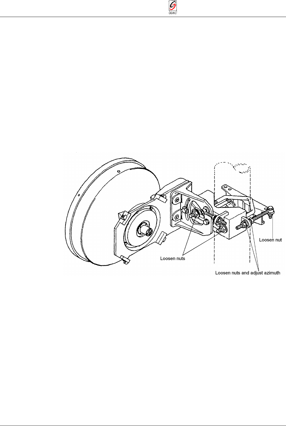
3.9.14.1. Azimuth Alignment
■ Loosen the nuts shown in the following figure and rotate the antenna
and mount, pointing it to the location of the opposing antenna.
■ Slowly sweep the antenna in azimuth using the azimuth adjustment
nuts.
■ If the desired signal is not found, increase or decrease elevation setting
and repeat the azimuth sweep.
Figure 3-23 Adjusting Azimuth - One Foot Antenna (with safety collar)
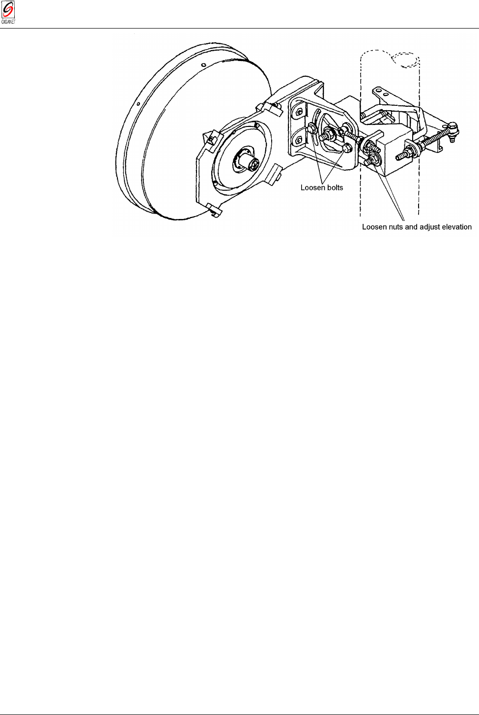
3.9.14.2. Elevation Alignment
■ Loosen elevation adjustment bolts and nuts to adjust elevation (refer to
the following figure).
■ Align pointer or edge of clamp with appropriate mark at the desired
elevation reading.
■ Make an approximate setting. Temporarily tighten elevation bracket
nuts.
FibeAir 1500 Installation & Operation Manual Chapter 3. Installation
Revision 2.0 Installation Instructions 3-25
Figure 3-24 Adjusting Elevation - One Foot Antenna
16. Once you attain the highest audible tone, disconnect the BNC headset
adapter.
This completes initial alignment of the system.
Chapter 3. Installation FibeAir 1500 Installation & Operation Manual
3-26 Installation Instructions Revision 2.0
3.10. Two Foot Antenna Assembly
3.10.1. Installing a Two Foot Antenna Assembly
For site requirements and pole installation, refer to sections 3.3 and 3.6.
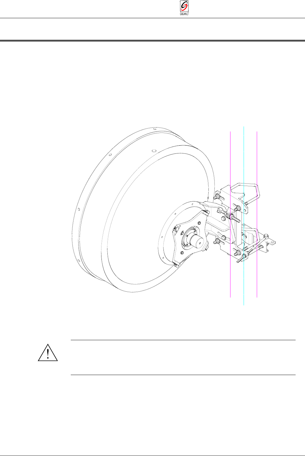
3.10.1.1. General
The following figure shows a two-foot antenna mounted on a pole.
Figure 3- 25 A Mounted Two Foot Antenna
3.10.1.2. Two Foot Antenna Assembly − Installation Instruction
Warning
It is important to mount the antenna exactly as described in this
installation instruction. Giganet disclaims any responsibility for the result
of improper or unsafe installation. These installation instructions have
been written for qualified, skilled personnel.
FibeAir 1500 Installation & Operation Manual Chapter 3. Installation
Revision 2.0 Installation Instructions 3-27
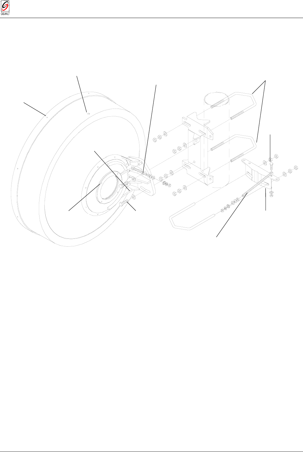
Perform the installation instructions according to the following figure.
Figure 3- 26 Antenna Assembly - Two Foot Antenna
8 screws B 4.2
Drain plug
Bolt M10 x 40
Bolt M8 x 30
Washer 8.4
SL nut M
8
Safety collar *
U bolt M10
2 washers 10.5 Ø 30
4 nuts M10
AZIMUTH spindle M8 *
2 brass nuts M8
2 spherical washers C 8.4
2 conical seats D 9.6
4 screws M5
4 washers 5.3 Ø 15 Bolt M10 x 40
Washer 10.5 Ø 30
ELEVATION spindle M8 x 90
2 brass nuts M8
2 spherical washers C 8.4
2 conical seats D 9.6
2 U bolts M10 with:
2 washers 10.5 Ø 30
4 nuts M1
0
Chapter 3. Installation FibeAir 1500 Installation & Operation Manual
3-28 Installation Instructions Revision 2.0
1. Place U bolt (A) and safety collar (B) around the pole at the desired
height, connect them and tighten in place at a 90° angle to the opposing
site.
Place around pole
desired height
a
n
d
t
i
g
h
t
e
n
(A)
(B)
Safety collar
Ubolt
Figure 3-27 Antenna Assembly - Two Foot Antenna (cont.)
Note
The safety assembly installed above ((A) and (B)) is used to support the antenna mount
during installation and antenna alignment. Once the mount is in place and alignment is
completed, all bolted joints are tightened and there is no further need for the support
provided by the safety assembly. It may then be removed for use in future installations.
FibeAir 1500 Installation & Operation Manual Chapter 3. Installation
Revision 2.0 Installation Instructions 3-29
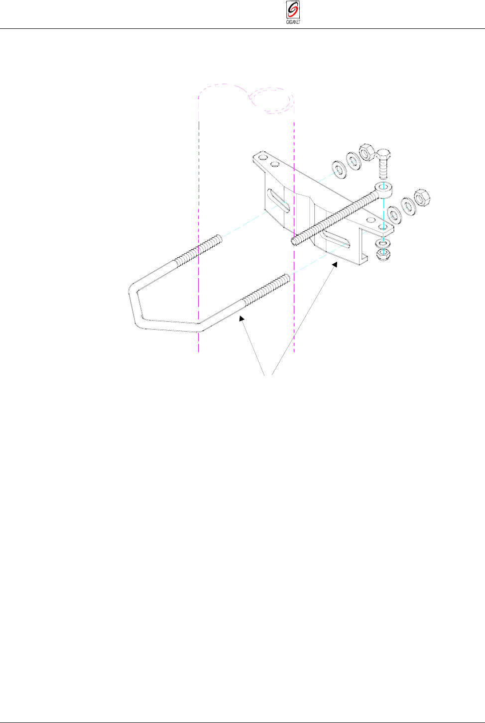
2. Place part (C) and U bolts (D) and (E) around pole on the safety collar
and tighten it.
Figure 3-28 Antenna Assembly - Two Foot Antenna (cont.)
Chapter 3. Installation FibeAir 1500 Installation & Operation Manual
3-30 Installation Instructions Revision 2.0
3. Connect part (F) to part (C). Before tightening the two parts together, set
the approximate elevation angle of part (F).
connect and ti
g
hten
set approximate elevation
angle and then tighten
n
uts and bolts
(C)
(F)
Figure 3- 29 Antenna Assembly - Two Foot Antenna (cont.)
FibeAir 1500 Installation & Operation Manual Chapter 3. Installation
Revision 2.0 Installation Instructions 3-31
4. Insert spindle (G) into hole (H) and connect spindle (G) to (I).Attach the
antenna to the antenna mount (H).
Figure 3- 30 Antenna Assembly - Two Foot Antenna (cont.)
* Safety collar and AZIMUTH spindle (on request)
(H)
(G) (I)
8 screws B 4.2
Drain plug
2 U bolts M10 with:
2 washers 10.5 Ø 30
4 nuts M1
0
Bolt M8 x 30
washer 8.4
Sl nut M8
Safety collar *
U bolt M10
2 washers 10.5 Ø 30
4 nuts M10
AZIMUTH spindle M8 *
2 brass nuts M8
2 spherical washers C 8.4
2 conical seats D 9.6
4 screws M5
ELEVATION spindle M8 x 90
2 brass nuts M8
2 spherical washers C 8.4
2 conical seats D 9.6
Insert spindle (G) into
hole (I) and connect
spindle (G) to (I)
Chapter 3. Installation FibeAir 1500 Installation & Operation Manual
3-32 Installation Instructions Revision 2.0
Make sure to install the antenna with the drain plug side up as shown in the
following figure.
Figure 3-31 Correct Orientation of Antenna
5. Roughly align the antenna with the opposing site. This may be done by
eyesight, using a compass or with the Giganet optical viewfinder.
Tip
It is sometimes difficult to identify the opposing site. For this reason, it is sometimes
helpful to have someone at the opposing site use a reflecting device, such as a hand-held
mirror, to reflect sunshine towards you.
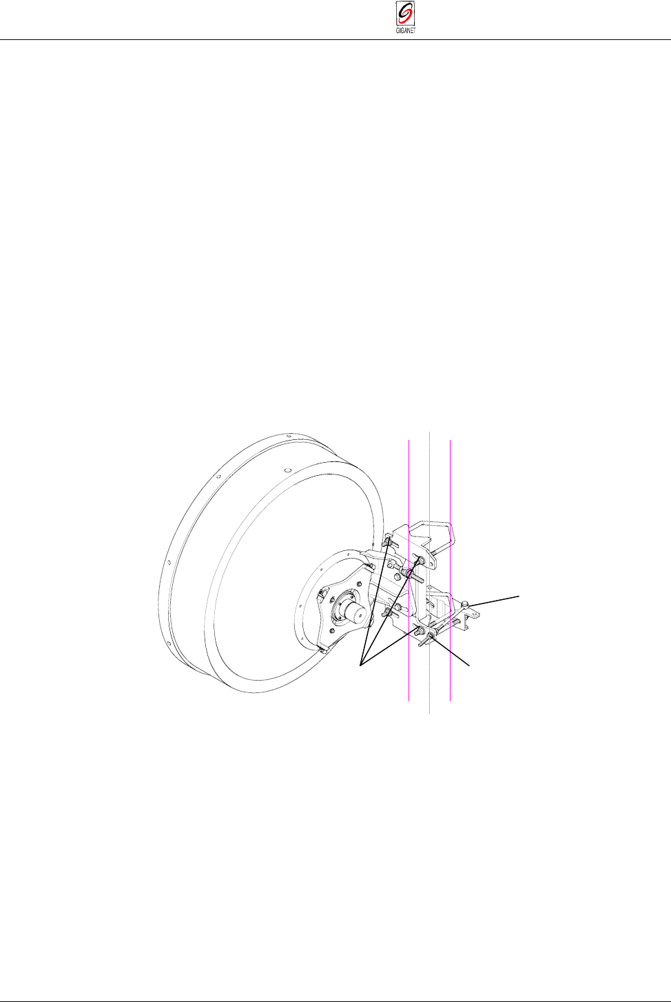
6. Attach the ODU to the mount assembly using the four latches on the
ODU (L). See the following.
Warning
To verify proper sealing, confirm existence of a rubber O-ring on the
antenna, as seen in the following figure.
Setting Polarity
Polarity is determined by the orientation of the ODU. If the handle of ODU is
facing up or down then the polarity is vertical. If the handle of the ODU is to
the side then the polarity is horizontal.
FibeAir 1500 Installation & Operation Manual Chapter 3. Installation
Revision 2.0 Installation Instructions 3-33
Figure 3-32 Attaching the ODU to the Mount Assembly
7. Connect the coaxial cable between the IDU and ODU using the N-Type
connectors on the IDU and the ODU.
Tip
Connect and disconnect the IDU from the ODU only when power is off.
8. Turn the power switch on the IDU to ON.
The LED display should appear as described below:
LED Color Explanation
PWR Green Power on
STBY Green Normal operation
BER Red Excessive bit errors detected
LINE Red No input to main channel/High BER
LBK Green Loopback not operated
LOF Red Loss of Frame detected (no radio connection)
IDU Green IDU operating and no IDU alarm
ODU Yellow Rx/Tx out of range
CBL Green Cable between ODU and IDU properly connected
RMT Red Remote unit not connected.
If the LED display is not as described above, refer to
Chapter 6 -
Troubleshooting & Diagnostics
.
9. Connect the headset BNC adapter to the ODU.
10. Connect the headset to the adapter and put it on.
Rubber
O-Ring
Chapter 3. Installation FibeAir 1500 Installation & Operation Manual
3-34 Installation Instructions Revision 2.0
3.10.2. Initial Antenna Alignment
−
Using the Headset
If a tone is heard,
your initial alignment is OK. Now you can adjust the aim
to find the highest tone pitch and proceed to the final alignment as
described in section 3.9.18.
If no tone is heard,
the initial alignment is not satisfactory. It is
recommended to use the mechanical aim for initial alignment.
In this case, loosen the azimuth bolts and adjust azimuth and tighten in the
position where the highest tone is heard. If this does not help, adjust
elevation and then azimuth. See directions below.
Note
We recommend that two people perform this installation and alignment procedure, one
at each ODU site, with some method of communications between them.
3.10.2.1. Azimuth Alignment
■ Loosen the nuts, as shown in the following figure, and rotate the
antenna and mount, pointing it to the location of the opposing antenna.
■ Slowly sweep the antenna in azimuth.
■ If the desired signal is not found, increase or decrease elevation setting
and repeat the azimuth sweep.
Figure 3- 33 Adjusting Azimuth - Two Foot Antenna
3.10.2.2. Elevation Alignment
■ Loosen elevation adjustment bolts and nuts to adjust elevation (refer to
the following figure).
■ Align pointer or edge of clamp with appropriate mark at the desired
elevation reading.
■ Make an approximate setting. Temporarily tighten elevation bracket
nuts.
Loosen nu
t
Loosen nuts and
adjust azimuth
Loosen nuts

FibeAir 1500 Installation & Operation Manual Chapter 3. Installation
Revision 2.0 Installation Instructions 3-35
Figure 3-34 Adjusting Elevation - Two Foot Antenna
11. Once you attain the highest audible tone, disconnect the BNC headset
adapter.
This completes the initial alignment of the system.
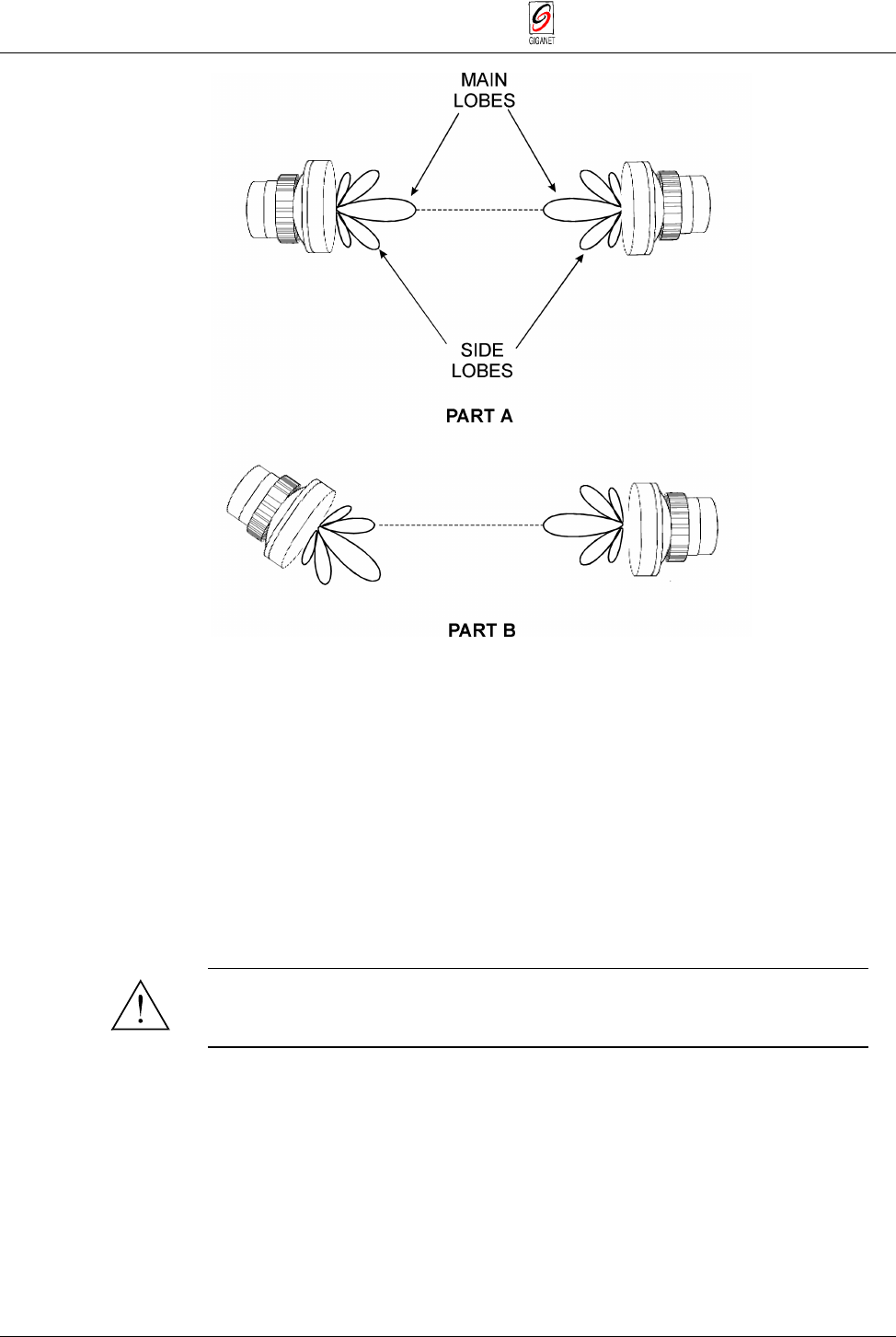
3.10.3. Alignment Verification
−
Checking Actual Receive Level
When pivoting the antenna ±2° in azimuth and elevation during antenna
alignment, three distinct lobes are probable: the two side lobes and the
center (main) lobe. To ensure optimum system performance, the center
lobe of the antenna must be aligned with the center of the opposing antenna
in the link.
The initial alignment procedure explained in the previous section allows you
to align the system to the peak of a lobe. However, it is difficult to make sure
that the system is aligned to the center lobe using the tone heard through
the headset. Therefore, following the initial alignment procedure you must
perform the final alignment verification explained below in order to make
sure that the system is aligned to the center lobe by verifying that the actual
received signal level corresponds to the expected receive signal level.
When the antenna is aligned to a side lobe, the expected RSL is at least
25dB less than the calculated unfaded RSL.
Loosen nuts and
adjust elevation
Loosen nuts
Chapter 3. Installation FibeAir 1500 Installation & Operation Manual
3-36 Installation Instructions Revision 2.0
Figure 3-35 Antenna Alignment
−
Main and Side Lobes
1. Connect a DVM (Digital Voltmeter) - BNC adapter to the ODU.
2. Set the DVM to 2 VDC.
3. Turn the DVM on.
The reading on the DVM indicates receive signal level.
For example, if -1.44V is displayed, receive signal level is -44 dBm.
4. Compare the value displayed on the DVM to the expected value
determined in section 3.9.11, step 2.
5. If the received signal level matches the expected level, tighten all bolted
joints and remove the safety assembly.
Important
It is important to verify that the antenna is aligned to the center lobe
peak. Proper alignment reduces the sensitivity to antenna movement,
which can be due to strong winds or any other forces.
3.10.4. Final Check
When the antenna is installed, make sure that all aspects of the installation
instructions have been followed. Check that all bolted joints are tightly
locked, and connect and cover the coax cable connector as follows:
1. Connect the coaxial cable between the IDU and ODU using the
N-Type connector on the IDU and the ODU.
FibeAir 1500 Installation & Operation Manual Chapter 3. Installation
Revision 2.0 Installation Instructions 3-37
2. Make sure that the fittings and the coax cable are clean and dry.
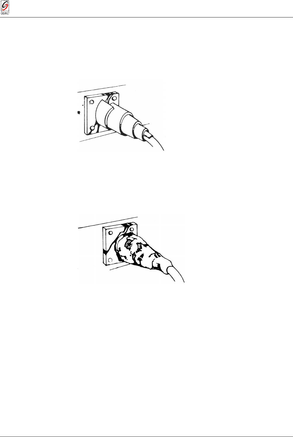
3. Peel approximately 6 inches of COAX-SEAL from the paper backing.
4. Wrap isolation tape over the coax cover. Start winding from coax cover
towards fitting with one half overlap with each winding making sure all
joints are well covered.
Figure 3-36 Steps 1, 2 & 3
5. After entire fitting and coax cable are covered with approximately 3/16"
thick layers, mold and form COAX-SEAL with fingers to make a smooth
surface and force out any air.
Figure 3- 37 Step 4
6. If more COAX-SEAL is necessary to complete seal simply cut the
needed amount and add to existing COAX-SEAL, molding and press into
the other material. COAX-SEAL adheres to itself with slight pressure.
Carefully inspect seal to make certain that all joints are covered
Chapter 3. Installation FibeAir 1500 Installation & Operation Manual
3-38 Installation Instructions Revision 2.0
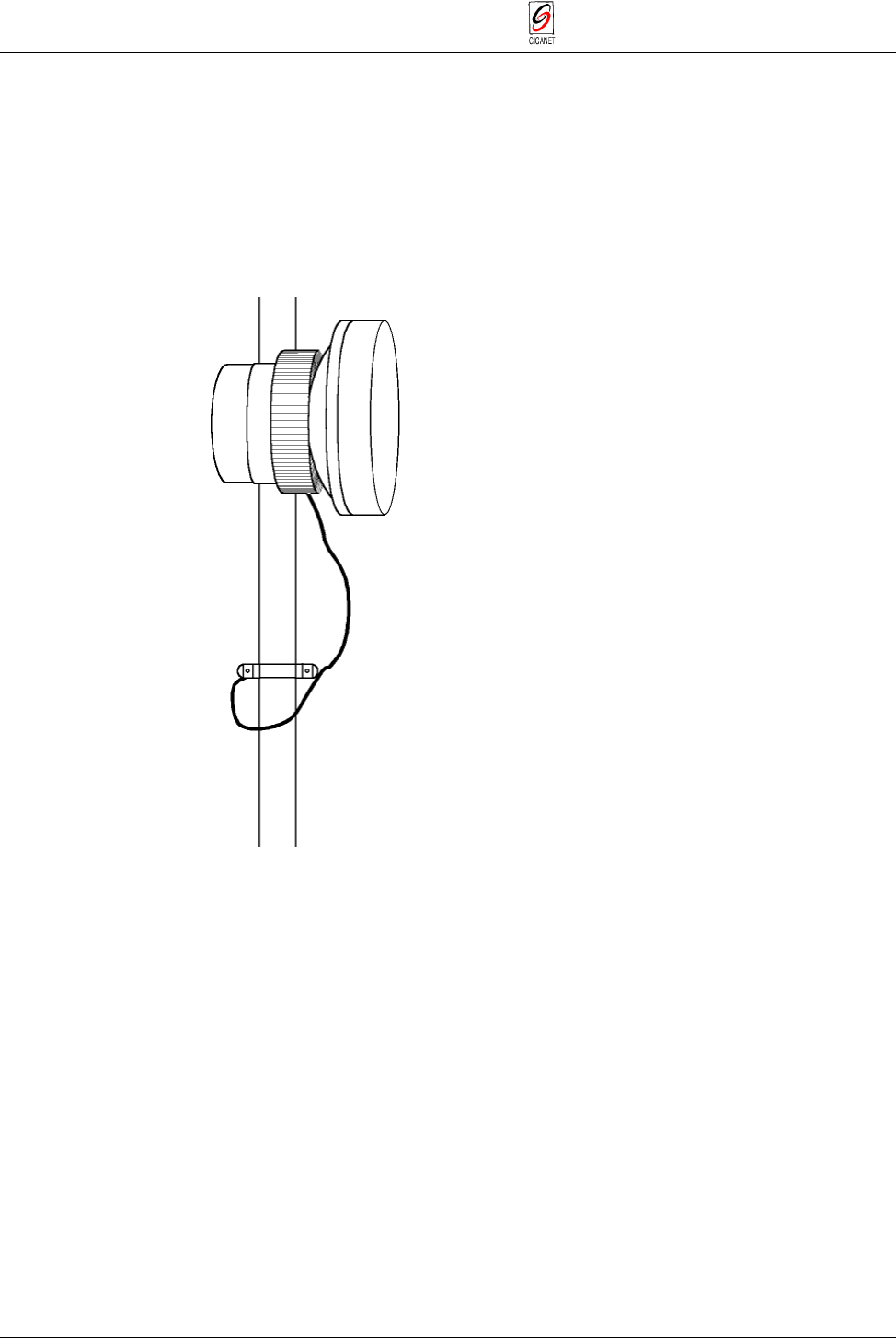
3.10.5. Safety and Grounding
The pole, antenna mount assembly and feed cables must be grounded in
accordance with current national and local electric codes to protect from
surges due to nearby lightning strikes. The following figure illustrates a
typical grounding method.
Clamps that provide a solid connection between ground wire and ground
source should be used.
Figure 3-38 Grounding the ODU Assembly
The ODU installation and initial alignment is now complete. Repeat this
procedure for the opposing ODU.
FibeAir 1500 Installation & Operation Manual Chapter 3. Installation
Revision 2.0 Installation Verification 3-39
3.11. Installation Verification
3.11.1. Using the Headset and Buzzer
Connect a headset to the headset connector on the IDU (both sides), verify
communications and test the buzzer (also on IDU front panel). Note that to
use the headset, the Engineering Order Wire option must be set to active.
The Engineering Order Wire is an audio connection between the two indoor
units.
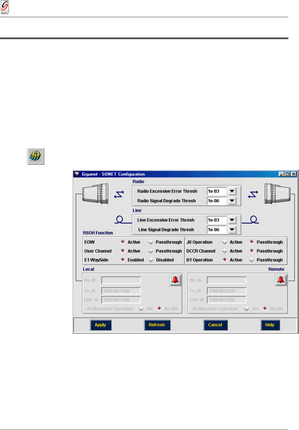
3.11.1.1. Verifying Activation of Engineering Order Wire (EOW)
To verify that the Engineering Order Wire (EOW) option is activated, follow
these steps:
1. Select Configuration ½ Sonet/SDH.
The Sonet/SDH Configuration window is displayed.
Figure 3-39 Sonet/SDH Configuration Window
2. In the first line of the RSOH Function section of the window, next to
EOW, click on Active (radio button should be filled ♦).
3. Click Apply.
4. Click Cancel.
The Sonet/SDH Configuration window is closed and you are returned to
the Work Area window.
Chapter 3. Installation FibeAir 1500 Installation & Operation Manual
3-40 Installation Verification Revision 2.0
3.11.2. Checking the Frequency Plan
1. Enter the Management software and select Configuration ½ Set
frequency.
The Frequency Plan window is displayed.
Figure 3-40 Frequency Plan Window
2. Verify that the lightning bolt between the two ODU images is displayed
in green.
FibeAir 1500 Installation & Operation Manual Chapter 3. Installation
Revision 2.0 Installation Verification 3-41
3.11.3. Checking the ODU Configuration
1. Select Configuration ½ ODU.
The ODU Configuration window is displayed.
Figure 3-41 ODU Configuration Window
2. Verify that the remote side of the ODU Configuration window is active
(values can be changed).
3. Verify that the Monitored Rx displayed is as previously measured by the
DVM (Unfaded RSL).
If any problems were encountered during the checks described above, refer
to
Chapter 6 - Troubleshooting & Diagnostics
.