Ceragon Networks GNT-FA1500-28 Point-to-Point digital radio User Manual FibeAir cover
Ceragon Networks Ltd. Point-to-Point digital radio FibeAir cover
Contents
- 1. chapter 4
- 2. chapter 5
- 3. chapter 2
- 4. chapter 3
chapter 4

Revision 2.0 Prerequisites 4-1
4.1. Prerequisites
The system setup and configuration follows the system installation, initial
testing and antenna alignment as described in chapter 3.
4.2. The Setup Procedure
The FibeAir 1500 setup procedure consists of the following operations :
1. Defining general settings
— Setting local device communication parameters
— Setting SNMP parameters
2. Defining system configuration parameters
— Setting transmit frequency
— Setting output power levels
3. Defining system information
— Date
— Time
— Name
— Contacts
— Location
4. Defining SONET/SDH configuration parameters
5. Defining management setup parameters
— Defining manager list
— Defining alarm groups
— Setting external alarm inputs
— Setting alarm outputs
FibeAir 1500 Installation & Operation Manual Chapter 4. System Setup
4-2 The Setup Procedure Revision 2.0
4.2.1. System Setup
To start the FibeAir 1500 radio link configuration you first need to setup the
Ethernet and PPP/SLIP IP addresses. Once you have defined these
addresses, you will be able to configure the system using the GiganetView
software.
To set the addresses, perform the following operations:
1. Connect the RS-232 port of your computer to the RS-232 (9-PIN) port
on the indoor unit front panel. This port is labeled “Terminal” and is
located near the front panel LEDs.
2. Connect to the standard Windows HyperTerminal at 19,200 bits per
second.
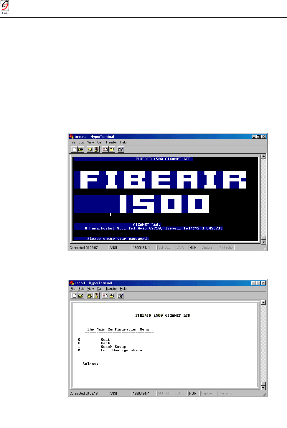
3. After you are connected, press Enter. The login menu appears.
Figure 4-1 FibeAir 1500 Terminal - Login Screen
4. Type giganet as the password. The main menu displays.
Figure 4-2 FibeAir 1500 Terminal - Main Configuration Menu

Chapter 4. System Setup FibeAir 1500 Installation & Operation Manual
Revision 2.0 The Setup Procedure 4-3
For a more detailed description of the HyperTerminal configuration
procedure, refer to the following section 4.2.2 – “Connecting to the
HyperTerminal.”
4.2.2. Connecting to the HyperTerminal
Setting Up the HyperTerminal Connection
To set up the HyperTerminal connection, perform the following operations:
1. Connect the RS232 port of your computer to the Terminal port of the
IDU.
2. Select Start ½ Programs ½ Accessories ½ Communication ½
HyperTerminal.
3. Double-click the HyperTerminal application icon.
4. In the Connection Description box, enter the name Terminal and click
OK.
5. In the Connect Using field (in the Phone Number box) select Direct to
Com 1 and click OK.
6. In the Port Settings tab (Com 1 Properties box) configure the following
settings:
— Bits per second – 19,200
— Data bits - 8
— Parity - None
— Stop bits - 1
— Flow control - Hardware
7. Click OK.
8. End the HyperTerminal connection.
Connecting to the Terminal
To connect to the terminal, perform the following operations:
1. Connect the RS232 port of your computer to the Terminal port of the
IDU.
2. Select Start ½ Programs ½ Accessories ½ HyperTerminal.
3. Double-click the Terminal connection icon. The HyperTerminal screen
opens.
4. Enter the password giganet and press Enter. The Main Configuration
Menu appears.
Note
: The Terminal screens are depicted here as black text on a white background for ease
of reading. The original screens are white text on black background.
FibeAir 1500 Installation & Operation Manual Chapter 4. System Setup
4-4 The Setup Procedure Revision 2.0
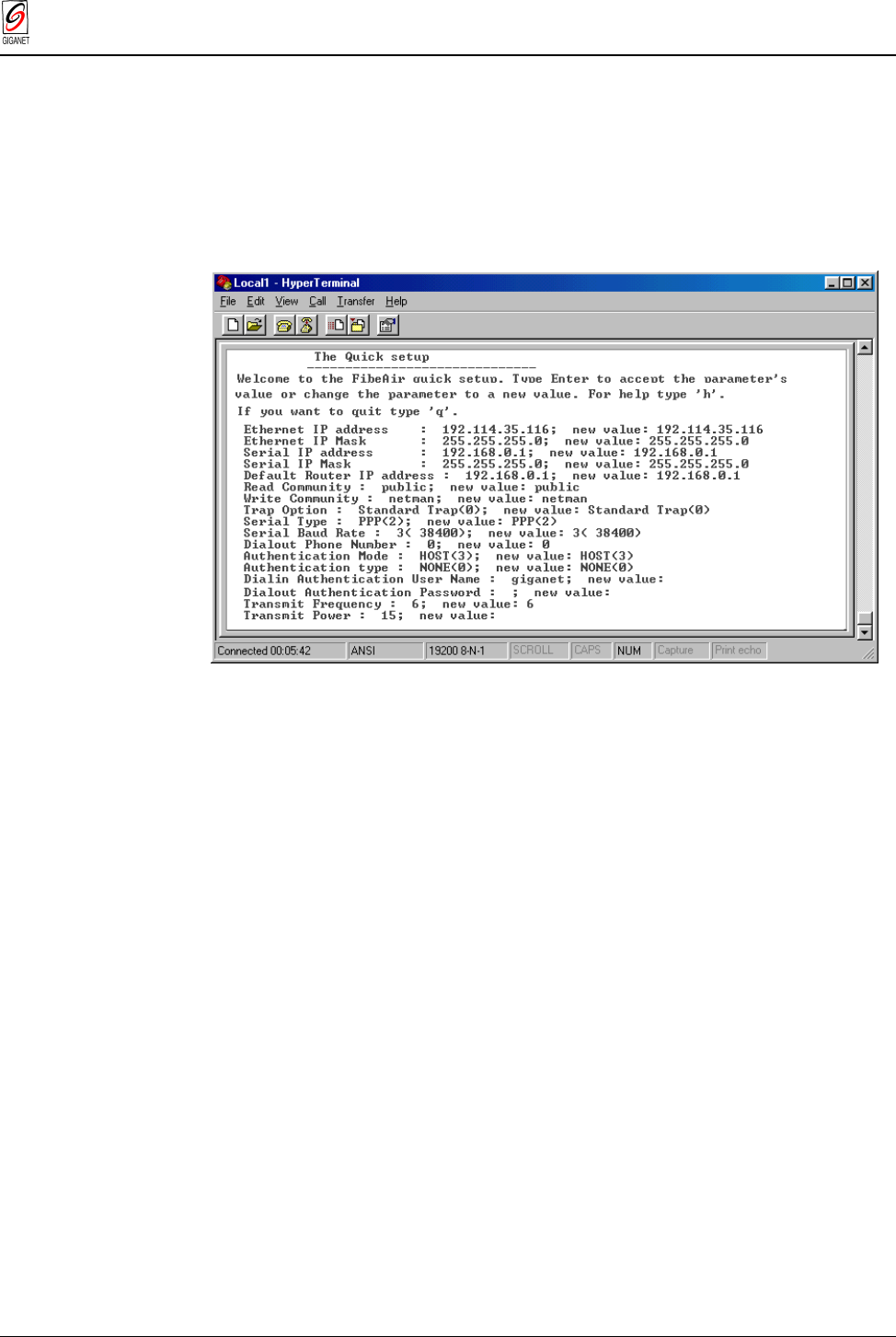
4.2.3. Quick Setup
To perform quick setup, carry out the following operations:
1. From the Main Configuration Menu, select 1 – Quick Setup and press
Enter. The Quick Setup menu appears.
Note
: Quick Setup is the recommended option if you are not familiar with the system.
More advanced users may use the Full Configuration menu.
Figure 4-3 FibeAir 1500 Terminal - Quick Setup Menu
2. Accept or change each parameter value. Press Enter to accept the
existing value or type in the new value in the space provided.
— Ethernet IP address: The FibeAir 1500 Ethernet port IP address
you wish to use.
— Ethernet IP Mask: Your network IP sub-net address.
— Serial IP address: The FibeAir 1500 Serial port IP address you wish
to use.
— Serial IP Mask: Your network IP sub-net address.
— Default Router IP address: The FibeAir’s default router address.
— Read community: The community password for read only devices.
— Write community: The community password for read/write devices.
— Trap option: “0” – sending standard trap, “1” – sending trap with
unit serial I.D. The recommended option is “0”.
— Serial Type: Defines the serial communication type, PPP or SLIP.
— Serial Baud Rate: Serial communication port baud rate.
— Dial-Out Phone Number: The phone number to be dialed by the
indoor unit.

Chapter 4. System Setup FibeAir 1500 Installation & Operation Manual
Revision 2.0 The Setup Procedure 4-5
The PPP protocol adds security to the communication and therefore
additional parameters need to be configured in the system:
— Authentication Protocol Type:
0 – None
1 – PAP (without encryption)
2 – CHAP (with encryption)
— Authentication Mode:
2 – GUEST. The IDU gives the user name and password to the
network manager.
3 – HOST. The IDU receives the user and password from the
network manager and validates them.
4 – DYNAMIC. When the IDU receives a phone call, it acts as a
HOST. If it initiates a call to the network manger (SNMP trap) it will
act like a GUEST. In case of a direct connection (without a dialup
modem) it acts as a HOST.
— Dial-In Authentication User Name: Enter the user name that is
used to validate a user dialing in to the indoor unit.
— Dial-In Authentication Password: Enter the password that is used
to validate a user dialing in to the indoor unit.
— Dial-Out Authentication User Name: Enter the user name that will
be used by the IDU to gain access to the remote manager.
— Dial-Out Authentication User Password: Enter the Password that
will be used by the IDU to gain access to the remote manager.
— Transmit Frequency: The frequency Channel number you wish to
use.
— Transmit Power: Power output level.
FibeAir 1500 Installation & Operation Manual Chapter 4. System Setup
4-6 The Setup Procedure Revision 2.0
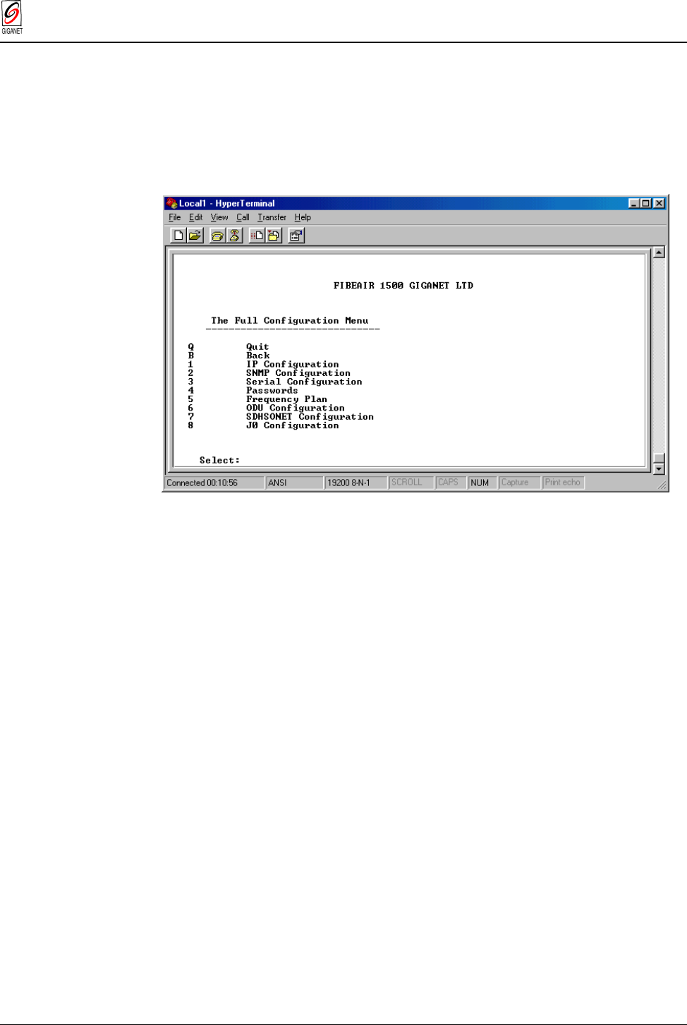
4.2.4. Full Configuration Setup
The Full Configuration menu allows you to fully configure the FibeAir 1500
system without connecting the GigaView application. The menu includes all
the options covered in the Quick Setup section plus some additional
configuration options that are normally accessed from the GigaView
application.
Figure 4-4 FibeAir 1500 Terminal - Full Configuration Menu
Selecting the relevant options from the Full Configuration menu will guide
you to the desired menu. The relevant operations are listed in each menu.
Chapter 4. System Setup FibeAir 1500 Installation & Operation Manual
Revision 2.0 The Setup Procedure 4-7
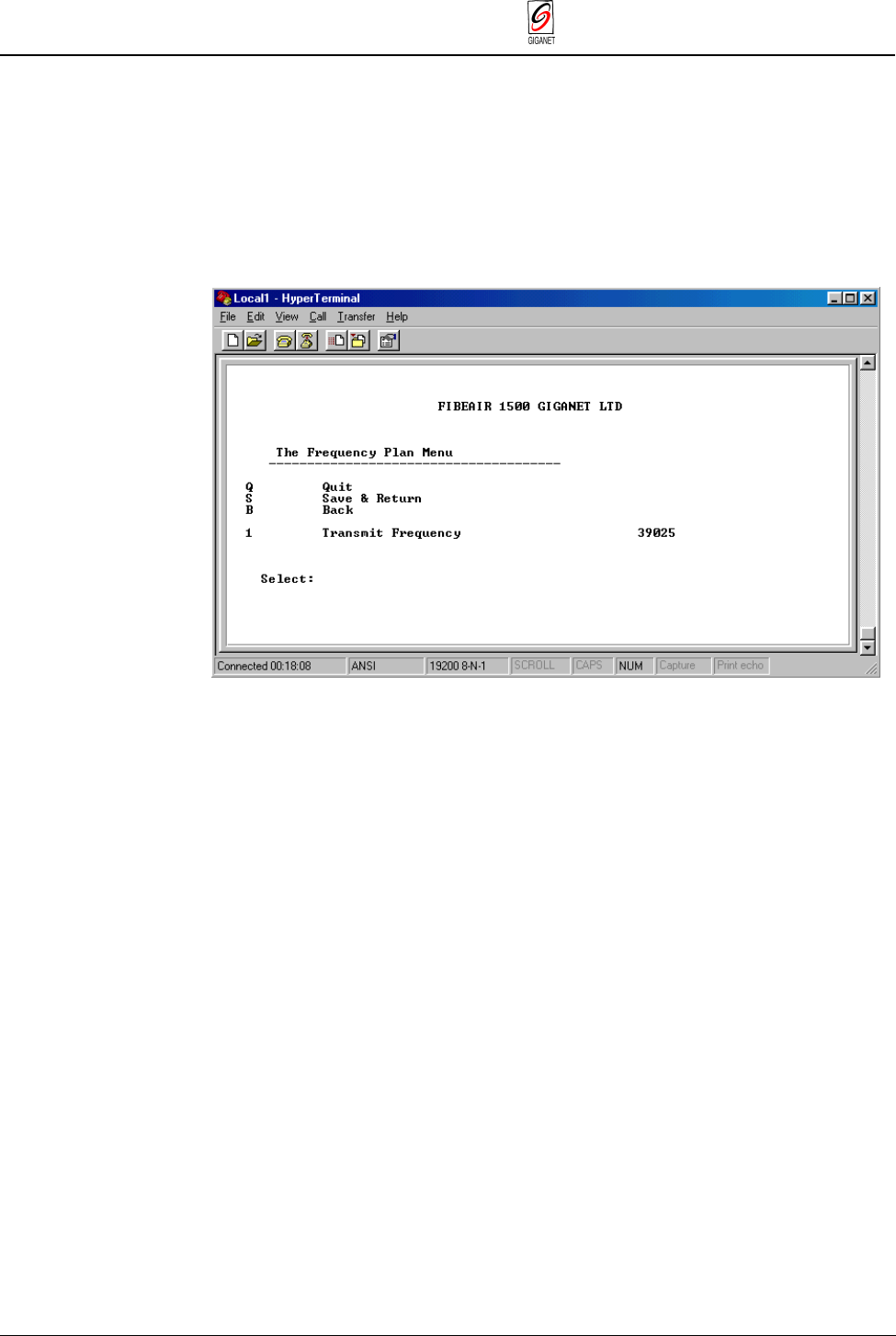
4.2.5. Setting the Frequency Channel
To set the frequency channel, perform the following operations:
1. Connect to the Terminal.
2. From the Main Configuration menu, select Full Configuration.
3. From the Full Configuration menu, select (5) Frequency Plan. The
Frequency Plan menu appears.
Figure 4-5 FibeAir 1500 Terminal - Frequency Plan Menu Menu
4. From the Frequency Plan menu, select (1) Transmit Frequency.
5. Enter the desired channel frequency.
6. Select (S) Save & Return to save the settings and return to the Full
Configuration menu.
FibeAir 1500 Installation & Operation Manual Chapter 4. System Setup
4-8 The Setup Procedure Revision 2.0
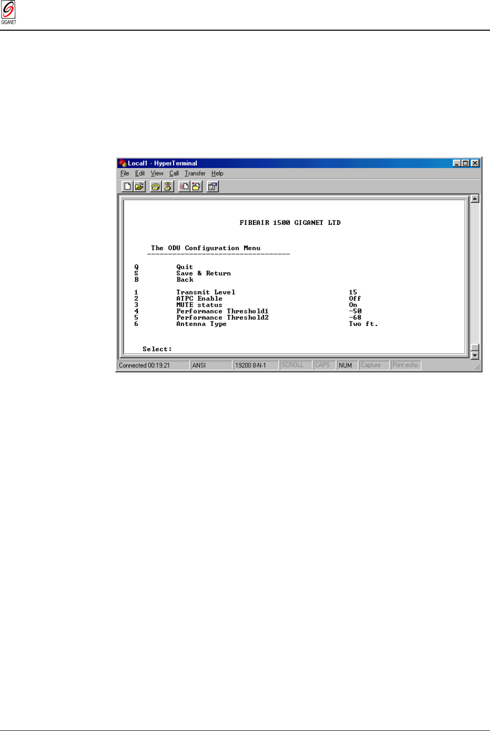
4.2.6. Setting the Transmit Power level
To set the transmitter power, perform the following operations:
1. Connect to the Terminal.
2. From the Main Configuration menu, select Full Configuration.
3. From the Full Configuration menu, select (6) ODU Configuration. The
ODU Configuration menu appears.
Figure 4-6 FibeAir 1500 Terminal - ODU Configuration Menu
4. Select (1) Transmit level.
5. Enter the desired transmit level. The acceptable values are between
–10 dBm to +15 dBm. Take into account the received level you expect
(the default received level is +15 dBm).
6. Select (S) Save & Return to save the settings and return to the Full
Configuration menu.
For frequencies other than 38 GHz, the transmit level can be higher than
15 dBm. Refer to Appendix E for more details.
Chapter 4. System Setup FibeAir 1500 Installation & Operation Manual
Revision 2.0 The Setup Procedure 4-9
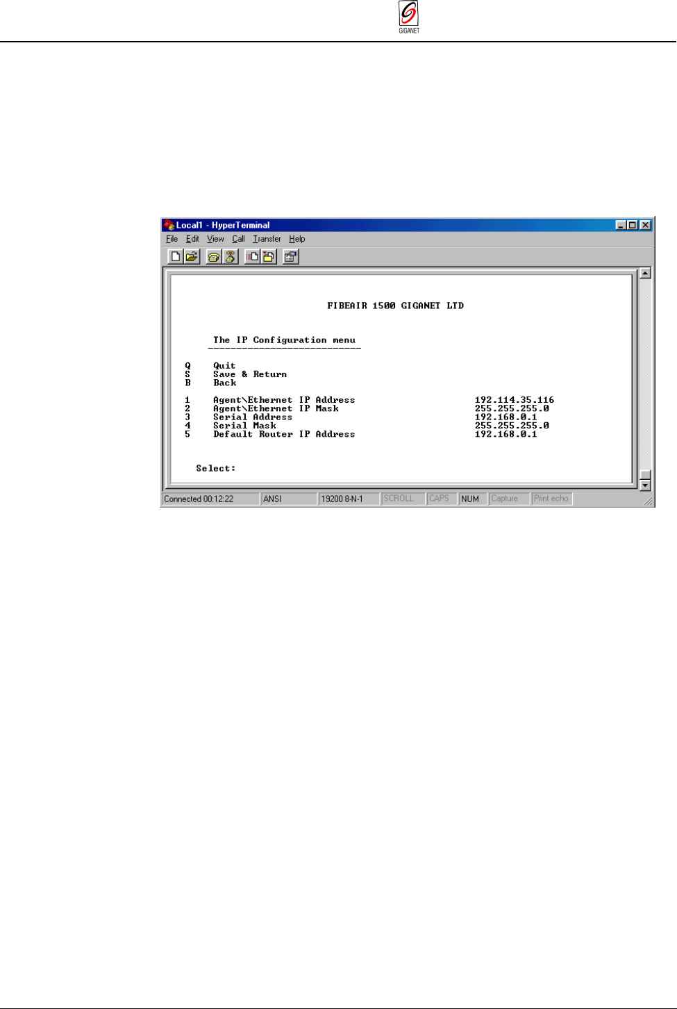
4.2.7. Setting the IP Addresses
To set the IP Addresses, perform the following operations:
1. Connect to the Terminal.
2. From the Main Configuration menu, select Full Configuration.
3. From the Full Configuration menu, select (1) IP Configuration. The IP
Configuration menu appears.
Figure 4-7 FibeAir 1500 Terminal - IP Configuration Menu
For Ethernet Configuration:
6. Select (1) Agent\Ethernet IP Address, and enter the IP address.
7. Select (2) Agent\Ethernet IP Mask, and enter the IP mask.
For Serial Communication (Slip, PPP, or Dial-up Modem):
8. Select (3) Serial Address, and enter the serial address.
9. Select (4) Serial Mask, and enter the serial mask.
10. Select (5) Default Gateway Router, and enter the router’s address.
11. Select (S) Save & Return to save the settings and return to the Full
Configuration menu.
12. Restart the IDU.
FibeAir 1500 Installation & Operation Manual Chapter 4. System Setup
4-10 The Setup Procedure Revision 2.0
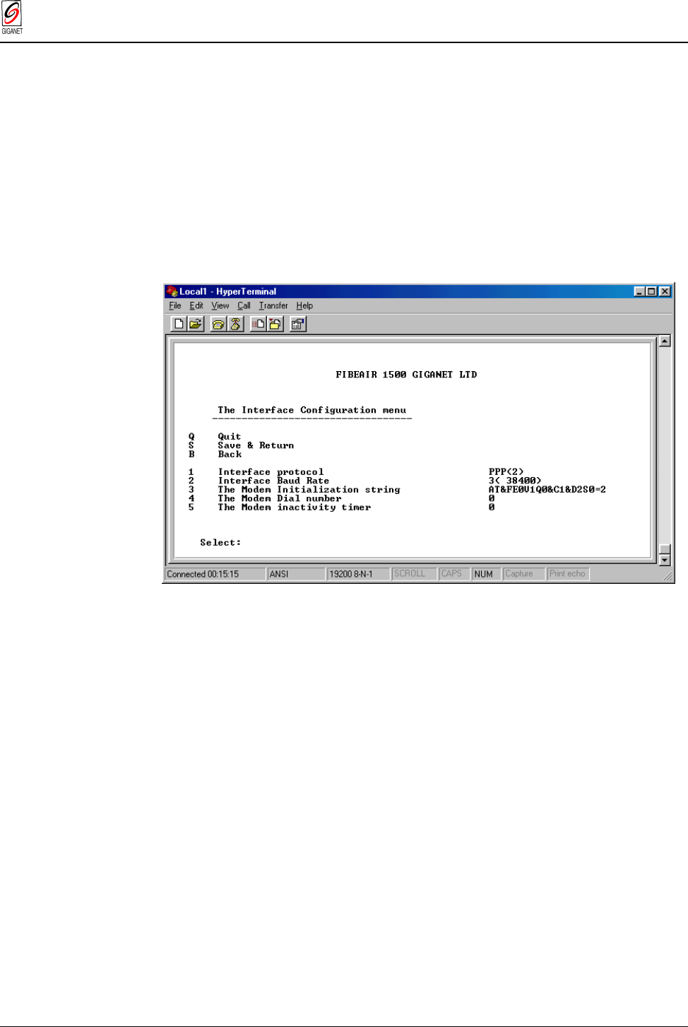
4.2.8. Configuring the Serial Communication Settings (Direct or Dial-Up Connection)
This configuration is required when a dial up modem or a computer is
connected to the IDU’s serial port. To configure the serial communication
setings, perform the following operations:
1. Connect to the Terminal.
2. From the Main Configuration menu, select Full Configuration.
3. From the Full Configuration menu, select (3) Serial Configuration.
4. From the Serial Configuration menu, select (1) Interface
Communication. The Interface Configuration menu appears.
Figure 4-8 FibeAir 1500 Terminal - Interface Configuration Menu
5. Select (1) Interface Protocol, and then select (2) PPP or (3) SLIP.
6. Select (2) Interface Baud rate, and then select the desired baud rate.
Note
: For a modem connection, choose no more than 19,200. For a direct connection to a
nearby computer, choose 38,400. Make sure that the same rate is defined in your network
manager’s dial up connection.
7. In (3) The Modem Initialization String, leave the default string.
Note:
Normally, the default should be used, unless the modem is connected through a
PABX or in any other special case. In these cases, consult Giganet Technical Service
department.
8. Select (4) The Modem Dial Number and enter a number if necessary.
Note:
This is the telephone number to which the network manager’s modem is connected.
9. Select (5) The Modem Inactivity Timer and enter the value “0”.
Note:
This parameter states how long should the phone call will remain active when no
data is transferred on the line. A value of 0 (zero), disables this inactivity timer.
10. Select (S) Save & Return to save the settings and return to the Full
Configuration menu.
Chapter 4. System Setup FibeAir 1500 Installation & Operation Manual
Revision 2.0 The Setup Procedure 4-11
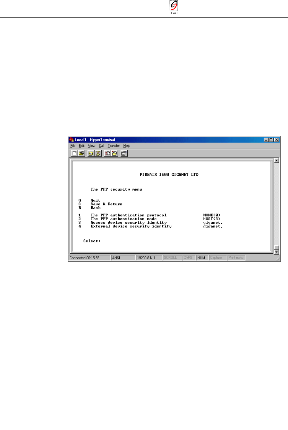
4.2.9. Configuring the PPP Security Settings
The PPP protocol adds security to the communication, and therefore,
additional parameters need to be configured in the system. This screen is
not relevant for a SLIP connection.
To configure the PPP Security settings, perform the following operations:
1. Connect to the Terminal.
2. From the Main Configuration menu, select Full Configuration.
5. From the Full Configuration menu, select (3) Serial Configuration.
3. From the Serial Configuration menu, select (2) PPP Security. The PPP
Security menu appears.
Figure 4-9 FibeAir 1500 Terminal - PPP Security Menu
4. Select (1) PPP Authentication Protocol. Define the protocol:
— 0 = None
— 1 = PAP (without encryption)
— 2 = CHAP (with encryption)
5. Select (2) PPP Authentication Mode.
— 2 = GUEST: The IDU gives the “user name” and the “password” to
the network manager.
— 3 = HOST: The IDU receives the “use name” and the “password”
from the network manager and validates them.
— 4 = DYNAMIC: When the IDU receives a phone call, then it acts as
HOST. If it initiates a call to the network manager (SNMP trap), it
will act like a GUEST. In case of a direct connection (without a
dialup modem), it acts as HOST.

FibeAir 1500 Installation & Operation Manual Chapter 4. System Setup
4-12 The Setup Procedure Revision 2.0
6. Select (3) Access Device Security Identity. Enter user name
(password).
This will be sent by the IDU when configured for authentication and acts
like a GUEST.
7. Select (4) External Device Security Identity. Enter user name
(password).
This will be received and validated by the IDU when configured for
authentication and acts like a HOST.
8. Select (S) Save & Return to save the settings and return to the Full
Configuration menu.
Chapter 4. System Setup FibeAir 1500 Installation & Operation Manual
Revision 2.0 The Setup Procedure 4-13
4.2.10. SNMP Configuration
To connect to the IDU with SNMP-based management, you need to define
the SNMP communities. These are passwords that define access rights of
different users. If these are not identical to the definitions in the network
management software (GiganetView or any other SNMP based software),
the authentication process will fail and access to the radio link is denied.
To configure the SNMP communities, perform the following operations:
1. Connect to the Terminal.
2. From the Main Configuration menu, select Full Configuration.
3. From the Full Configuration menu, select (2) SNMP Configuration. The
SNMP Configuration menu appears.
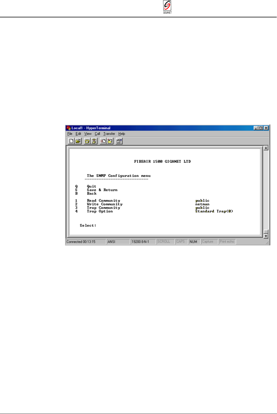
Figure 4-10 FibeAir 1500 Terminal
–
SNMP Configuration Menu
4. Select (1) Read Community and set it to public. Users with this
community will be allowed to read the link information, but will not be
allowed to change anything.
5. Select (2) Write Community and set it to netman. Users with this
community will be allowed to read and modify link information.
6. Select (3) Trap Community and set it to public. This password will be
used by the IDU when it reports to a SNMP based manager. The same
password needs to be included in the manager itself.
7. Select (4) Trap Option and set it to Standard Trap (0). In the “Standard
Trap” option, serial numbers will be added only to the private MIB traps.
Otherwise, serial numbers will be added to all SNMP traps.
8. Select (S) Save & Return to save the settings and return to the Full
Configuration menu.
9. Restart the IDU.

FibeAir 1500 Installation & Operation Manual Chapter 4. System Setup
4-14 Connecting to the IDU - Gigaview Revision 2.0
4.3. Connecting to the IDU - Gigaview
You can perform the physical connection to the IDU using one of the
following methods:
■ By connecting via the Ethernet port
■ By connecting via the serial port using PPP/SLIP
■ By connecting via the serial port using a dial-up modem
4.3.1. Connecting Via the Ethernet Port
1. Connect an Ethernet cable to the Ethernet port of the IDU. If the IDU is
connected directly to the computer, use a cross cable. If the IDU is
connected to a LAN (wall socket), use a standard straight cable.
2. Set the Ethernet IP address and mask to the IDU using the
HyperTerminal. The default Agent/Ethernet IP address is 192.168.1.1
and the Agent/Ethernet IP mask is 255.255.255.0
3. Make Sure the Ethernet IP address of your PC is on the same sub-net as
the IDU’s Ethernet IP address, and that the masks are identical.
4. Check and change the Ethernet address of the PC as follows:
Window 95/98:
— Select Start ½Settings ½Control Panel ½Network.
— Select the TCP/IP Ethernet component that was installed on the PC
and click Properties.
— On the IP Address tab select Specify an IP Address and enter the
appropriate IP address and mask.
Windows NT:
— Select Start ½Settings ½Control Panel ½Network.
— Select Protocols, then select TCP/IP protocol and then click
Properties.
— On the IP Address tab select Specify an IP Address and enter the
appropriate IP address and mask.
5. To verify connectivity, ping the IDU’s Ethernet IP address and make sure
you have a reply as follows:
— Select Start ½Run and in open field of the Run box, type ping
followed by the IP address.
6. Run the GiganetView management application.

Chapter 4. System Setup FibeAir 1500 Installation & Operation Manual
Revision 2.0 Connecting to the IDU - Gigaview 4-15
4.3.2. Connecting Via the Serial Port Using PPP/SLIP
1. Connect an RS-232 9-pin cable to the serial port of the IDU.
2. Install a PPP or SLIP driver. Refer to Appendix A for details.
3. Set the serial IP address and mask of the IDU using the Hyper-
Terminal. The default serial IP address is 192.168.10.1 and the serial IP
mask is 255.255.255.0.
4. Make sure that the serial IP address of your PC is on the same sub-net
as the IDU’s serial IP address, and that the masks are identical.
Window 95/98:
5. Check and change the serial address of the PC as follows:
— Select Start ½Settings ½Control Panel ½Network.
— Select the TCP/IP Dial-up Adapter component that was installed on
the PC and click Properties.
— On the IP Address tab select Specify an IP Address and enter the
IP address and mask that are on the same sub-net as the IDU you
want to connect to.
— Make sure that the serial IP address of the PPP/SLIP driver you
have installed is on the same sub-net as the IDU’s serial IP address,
and the masks are identical.
6. To check and change the serial address of the PPP/SLIP driver double-
click My Computer.
7. Double-click Dial-up Networking.
8. Click the icon that was added after the installation of the PPP/SLIP
driver, and select Properties.
9. Verify that the protocol (PPP or SLIP) and the baud rate match the
serial configuration that was set on the HyperTerminal.
10. Select Server Type and click TCP/IP Setting.
11. Select Specify IP Address and enter address on the same sub-net as
the serial address of the IDU.
12. Double-click this icon whenever you would like to establish
communication with the IDU.
Windows NT:
5. To check and change the serial address of the PPP/SLIP driver double-
click My Computer. Double-click Dial-Up Networking.
6. Click More, select Edit entry and modem properties.
7. On the Basic tab verify that you are dialing using NT Direct
Connection.
8. Click Configure and verify that the Initial speed (bps) is as configured
on the HyperTerminal.

FibeAir 1500 Installation & Operation Manual Chapter 4. System Setup
4-16 Connecting to the IDU - Gigaview Revision 2.0
9. Select Server tab and chose PPP or SLIP as your Dial-up server
type. Verify that the protocol (PPP or SLIP) and is in accordance to
the serial configuration that was set on the Hyper Terminal.
10. Check only TCP/IP then Click TCP/IP Settings.
11. Select Specify IP Address and enter address on the same sub-net
as the serial address of the IDU.
12. Make sure that Server assigned name server addresses is
selected and Use IP header compression and Use default
gateway on remote network are unchecked.
13. Whenever you wish to connect to the IDU, double-click Dial-Up
Networking and select the number you wish to dial at the
Phonebook Entry.
14. To verify connectivity, ping the IDU’s Ethernet IP address and make
sure you have a reply: Select Start Í Run and open ping
IP
address
.
Once communication is established, run the GiganetView management
application.

Chapter 4. System Setup FibeAir 1500 Installation & Operation Manual
Revision 2.0 Connecting to the IDU - Gigaview 4-17
4.3.3. Connecting Via a Serial Port Using a Dial-Up Modem
Setup
1. Double-click My Computer and then double-click Dial-up Networking.
2. Double-click Make New Connection. Type a name for the new
connection (Giganet, for example), and select the modem you are using
to dial.
3. Click Configure. On the General tab, set the maximum speed available
and uncheck the Only connect at this speed box.
4. On the Connection tab set Data bits =8, Parity = none, and
Stop bits =1.
5. Check the Wait for dial tone box and uncheck the Call if not
connected in 90 seconds box.
6. Uncheck Disconnect a call if idle for more than … seconds.
7. Click Port Settings and check Use FIFO Buffers and then click OK.
8. Click Advanced and uncheck the Use error control and Use flow
control boxes.
9. Make sure that Modulation type is set to Standard.
10. Click Server Type and select PPP or SLIP as Dial-up Server. Check
only TCP/IP.
11. Make sure that you select the serial interface that was configured in the
Hyper Terminal.
12. Click TCP/IP Settings and specify an IP address. The IP address
should be on the same sub-net as the serial address of the IDU.
13. Select Server assigned name server addresses and uncheck the
Use IP header compression and Use default gateway on remote
network boxes.

FibeAir 1500 Installation & Operation Manual Chapter 4. System Setup
4-18 Connecting to the IDU - Gigaview Revision 2.0
Modem
1. Connect the modem to the serial port of the IDU and to an analog
telephone line.
2. Make sure that the cable for the modem has the following pin-out:
DB9 DB25
120
22
33
48
57
75
84
Isolated shields
3. When using a standard modem, the dip-switch configuration should be
set as follows: Switches 3 & 8-down (Display results codes & Smart
mode).

Chapter 4. System Setup FibeAir 1500 Installation & Operation Manual
Revision 2.0 Logging In 4-19
4.4. Logging In
To perform the management operations, enter the management software,
as explained below.
1. Select Start ½ Program ½ GiganetView.
After the RunEnv Parameters window (Figure 3-7) the Login window is
displayed.
Figure 4-11 Login Window
2. To log in, enter your password and click OK.
By default, your initial read/write password is giganet. This password
can be changed later.
After logging in, the Work Area and Physical View windows are
displayed.
FibeAir 1500 Installation & Operation Manual Chapter 4. System Setup
4-20 Defining System Information Revision 2.0
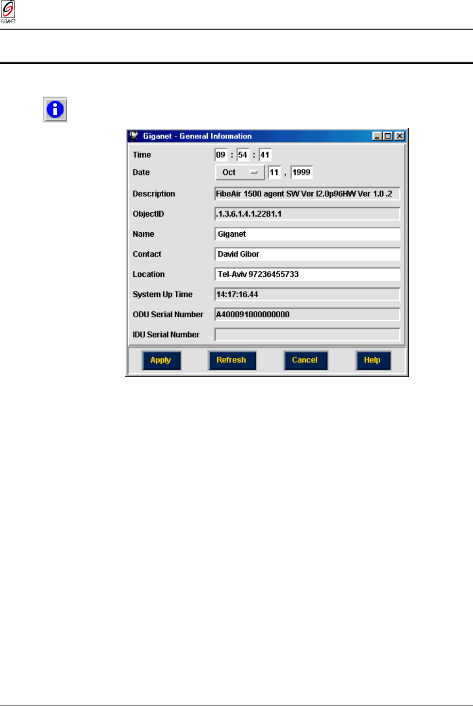
4.5. Defining System Information
1. Select Configuration ½ System Information.
The General Information window is displayed.
Figure 4-12 General Information Window
2. In the Time field, enter the current time of day in HH:MM:SS format.
3. In the Date field, select the month using the pull-down menu and enter
the day of the month and year.
The Description field is read-only. It displays a textual description of the
entity. This value should include the full name and identification of the
system’s hardware type, software operating system, and networking
software.
The Object ID field is read-only. It displays the vendor’s authoritative
identification of the network management system contained in the entity.
4. (Optional) In the Name field, enter an administrative-assigned name for
this managed node (link). By convention, this is the node’s fully-qualified
domain name.
5. (Optional) In the Contact field, enter the name of a person to contact in
case of problems with the system.
This should include textual identifier of the contact person for this
managed node, together with information on how to contact this person.
6. (Optional) In the Location field, enter the actual physical location of the
node or agent (e.g., ‘telephone closet, 3rd floor’).
Chapter 4. System Setup FibeAir 1500 Installation & Operation Manual
Revision 2.0 SONET/SDH Configuration (Optional) 4-21
The System Up Time field is read-only.
The ODU Serial Number field is read-only. It displays the serial number of
the ODU unit.
The IDU Serial Number field is read-only. It displays the serial number of
the IDU unit.
7. Click Apply.
The definitions and settings determined in the General Information
window are saved.
8. Click Cancel.
The General Information window is closed and you are returned to the
Work Area window.
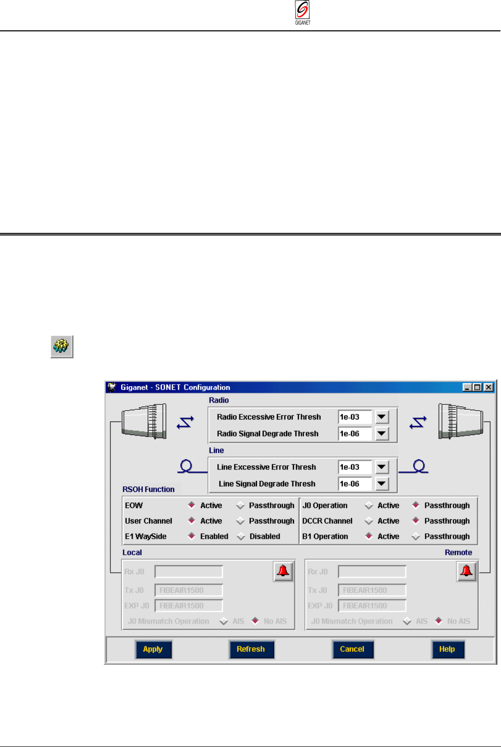
4.6. SONET/SDH Configuration (Optional)
The SONET/SDH Configuration window allows you to change threshold
levels for the radio and SONET/SDH alarms and to configure special
SONET/SDH transmission parameters. This is recommended for advanced
users only.
1. To define SONET/SDH Configuration, select Configuration ½
SONET/SDH.
The SONET/SDH Configuration window is displayed.
Figure 4-13 SONET/SDH Configuration Window

FibeAir 1500 Installation & Operation Manual Chapter 4. System Setup
4-22 SONET/SDH Configuration (Optional) Revision 2.0
Radio BER Alarm Thresholds (Optional):
2. In the Radio Excessive Error Thres field, select the level above which an
Excessive BER alarm is issued.
3. In the Radio Signal Degrade Thres field, select the level above which a
Signal Degrade alarm is issued.
Line Parameters (Optional):
4. In the Line Excessive Error Thres field, select the level above which an
Excessive alarm is issued.
5. In the Line Signal Degrade Thres field, select the level above which a
Signal Degrade alarm is issued.
Regenerator Section Overhead (RSOH) Function Parameters
(Required):
This section of the window allows you to determine the RSOH parameters
which will be used.
6. Set each RSOH parameter that will be used as
active
and leave the
others set as
passthrough
.
By default, these parameters are set to
passthrough.
EOW – Engineering Order Wire.
End to end voice channel option – E1 byte at the SDH RSOH –
activate/passthrough.
User channel – The 64 kbps user channel – F1 byte at the SDH RSOH
– activate/passthrough
E1 wayside – enable/disable the wayside channel.
JO operation – JO byte is used as a trace identifier at the SDH RSOH.
If JO is activated, use the “Tx JO” and “Exp JO” to define IDU identifier
string and “AIS” mode of operation.
DCCR – activate/passthrough the RSOH communication channel
normally used for inband TMN.
B1 operation – activate/passthrough B1 byte at the RSOH. B1 is used
to perform parity byte checks for monitoring SDH quality and service.
7. Click Apply.
The definitions and settings determined in the SONET/SDH
Configuration window are saved.
8. Click Cancel.
The SONET/SDH Configuration window is closed and you are returned
to the Work Area window.
Chapter 4. System Setup FibeAir 1500 Installation & Operation Manual
Revision 2.0 Management Setup (Optional) 4-23
4.7. Management Setup (Optional)
This section is required for network management configuration. If your
application only requires stand alone management, you may skip the
following procedure.
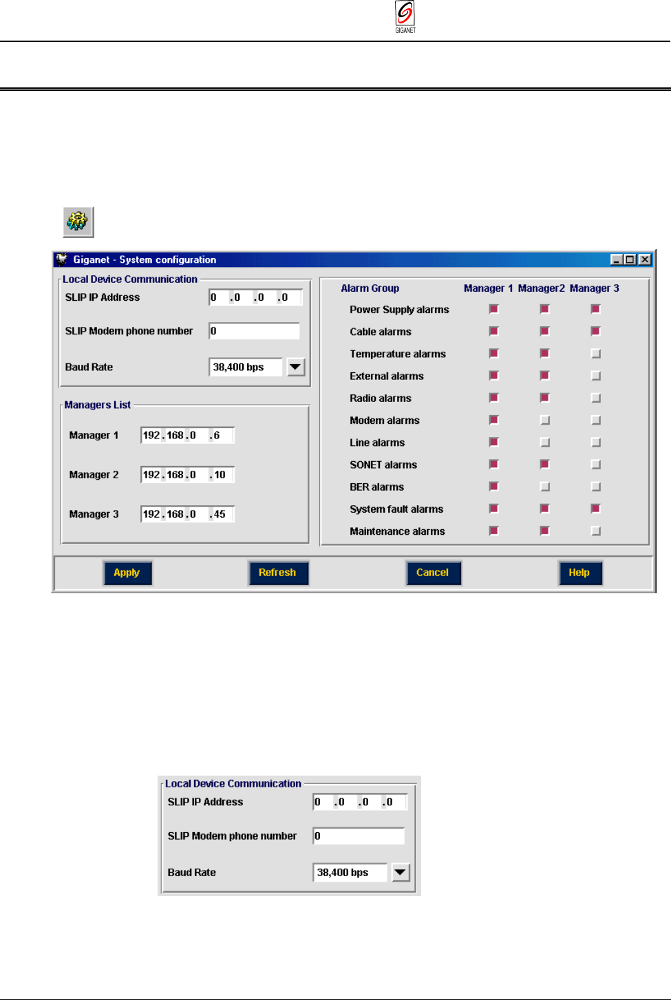
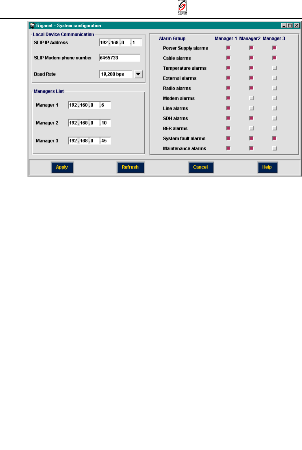
1. Select Configuration ½ General Settings.
The System configuration window is displayed.
Figure 4-14 System Configuration window
The System Configuration window is divided into three sections:
■ Local Device Communication Parameters
■ Managers List
■ Alarm Groups.
4.7.1. Setting Local Device Communication Parameters
Figure 4-15 Local Device Communication Parameters
FibeAir 1500 Installation & Operation Manual Chapter 4. System Setup
4-24 Management Setup (Optional) Revision 2.0
1. In the
SLIP IP Address
field, set the SLIP IP Address column to zeros.
2. (Optional) In the
SLIP Modem phone number
field, enter the SLIP
Modem phone number.
3. In the
Baud Rate
field, Select the baud rate of your modem.
The baud rate of the PC and the FibeAir 1500 system must be the same in
order to provide a valid connection between the PC and the IDU. By default,
the IDU’s baud rate is set at 19,200. For details on how to set the PC baud
rate, refer to section 3.9.7.
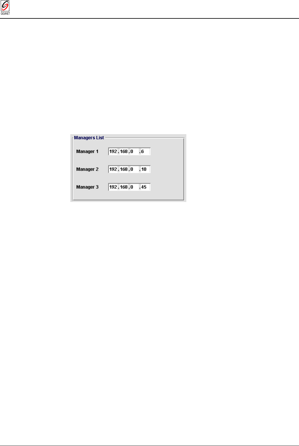
4.7.2. Defining the Managers List
The Managers List section of the System Configuration window allows you
to determine up to three managers to whom the system alarms can be sent.
Figure 4-16 Managers List
1. Enter the IP addresses of up to three system managers.
4.7.3. Defining Alarm Groups
The Alarm Groups section of the System Configuration window allows you
to determine which alarms are included in the log file of each manager
using the Alarm Group section of the window.
1. In the column of each manager, click on the types of alarms you want to
include in the log file of that manager.
Chapter 4. System Setup FibeAir 1500 Installation & Operation Manual
Revision 2.0 Management Setup (Optional) 4-25
Figure 4-17 Alarm Group Window
2. Click Apply.
The definitions and settings determined in the System Configuration
window are saved.
3. Click Cancel.
The System Configuration window is closed and you are returned to the
Work Area window.
FibeAir 1500 Installation & Operation Manual Chapter 4. System Setup
4-26 External Alarms Setup Revision 2.0
4.8. External Alarms Setup
The procedure detailed in this section is required only if external equipment
alarms are connected to the IDU or if the IDU alarm outputs are connected
to other equipment (using the alarms I/O connector).
1. To define IDU Configuration select Configuration ½ IDU.
The IDU Configuration window is displayed.
Figure 4-18 IDU Configuration Window
Follow the steps below for both the Local and Remote sides:
4.8.1. Setting External Alarm Inputs
The microcontroller in the IDU reads the alarm inputs (dry contact) and
transmits them over the management channel to the GiganetView
management system. This allows the FibeAir 1500 system to report external
alarms not related to itself. For each alarm:
1. Click on the box next to the alarm number to enable/disable. Alarms that
are enabled are indicated by a filled box (n); disabled alarms are
indicated by (o).
2. Enter a description of the alarm.
3. Select the alarm’s severity (Major, Minor, Warning or Event).

Chapter 4. System Setup FibeAir 1500 Installation & Operation Manual
Revision 2.0 External Alarms Setup 4-27
4.8.2. Setting Alarm Outputs
The FibeAir 1500 provides five alarm outputs which may be used by other
systems to sense FibeAir 1500 alarms.
Figure 4-19 Setting Alarm Outputs
The alarm outputs are Form C Relays. Each alarm output relay provides
three pins:
Normally open (NO)
Normally Closed (NC)
Common (C).
Any output alarm may be defined as any one of the following:
Major
Minor
Warning
External
Power
BER
Line
Loopback
LOF
IDU
ODU
Cable
Remote
The default alarm output settings are:
Relay 1: On-Line (Power)
Relay 2: IDU
Relay 3: ODU
Relay 4: CBL (Cable)
Relay 5: RMT (Remote)
These relays may be connected to customer-specific applications. Refer to
Appendix B for details on the alarm connector pin assignments.

FibeAir 1500 Installation & Operation Manual Chapter 4. System Setup
4-28 Line Interface Connection Revision 2.0
4.9. Line Interface Connection
After setting up all the previous parameters and establishing the radio link,
the Line Interface can be connected to the IDU.
All the available interfaces of the FibeAir 1500 system are described in
Chapter 8.
The terminology used with the interfaces is:
Connectors or signals labeled as “TX” indicates that the signal is a signal
outbound from the FibeAir 1500.
Connectors or signals labeled as “RX” indicates that the signal is a
signal inbound to the FibeAir 1500.