Ceragon Networks GNT-FA1500-28 Point-to-Point digital radio User Manual FibeAir cover
Ceragon Networks Ltd. Point-to-Point digital radio FibeAir cover
Contents
- 1. chapter 4
- 2. chapter 5
- 3. chapter 2
- 4. chapter 3
chapter 2

Revision 2.0 System Block Diagram 2-1
2.1. System Block Diagram
This chapter presents FibeAir 1500 basic principles of operation. The
FibeAir 1500 design concept is based on universal radio architecture.
A radio link consists of two FibeAir 1500 terminals. Each terminal includes
three major LRU’s, IDU, ODU and the Antenna. A single cable, carrying
communications and DC power, interconnects the IDU with the ODU.
Figure 2-1 presents FibeAir 1500 main blocks and modules.
Figure 2-1 FibeAir 1500 System Block Diagram

Chapter 2. Theory of Operation FibeAir 1500 Installation & Operation Manual
2-2 In Door Unit (IDU) Revision 2.0
2.2. In Door Unit (IDU)
The IDU is a compact, 17” wide, 1U-high unit, mount compatible for both
ETSI and ANSI standard racks. The IDU modulates/demodulates the
155Mbps Sonet/SDH payloads, manages local and remote units, provides
I/O line alarms, and provides interfaces for 1.544/2.048 Mbps Wayside
channel, 64Kbps User channel and 64Kbps Order Wire channel.
The IDU also interfaces a Local Maintenance Terminal or Network
Management System. In addition, status alarms and indicators are provided
on the front panel.
The IDU major modules:
n Multiplexer
n Modem
n Manager Card
n Cable Interface
n Power Supply
2.2.1. Multiplexer
The Mux module functions as a Sonet/SDH Regenerator. On the line side it
interfaces the OC-3/STM-1 stream, and on the radio side the Modem
module.
As a regenerator, the MUX either terminates or regenerates the
OC-3/STM-1 RSOH. In one direction, the OC-3/STM-1 stream, interfacing
through the MUX’s Rx line input terminates and the resulting stream is
transmitted to the Modulator in the Modem module.
In the opposite direction, the stream coming from the Modem’s
Demodulator, undergoes OC-3/STM-1 Regeneration in the MUX, and
transmitted through the MUX’s Tx line output.
In addition, the MUX module uses the OC-3/STM-1 SOH bytes to support
other services: 1.544/2.048 Mbps Wayside channel and management, 64
Kbps User Channel and Order Wire channel.
The MUX module may be configured via software for transparency of most
of the SOH bytes for maximum system transparency and non-intervention,
at the cost of reduced functionality and services.
The multiplexer module enables to integrate different interfaces and
services into the SDH payload to converge Datacom and Telecom
applications.
FibeAir 1500 Installation & Operation Manual Chapter 2. Theory of Operation
Revision 2.0 In Door Unit (IDU) 2-3
2.2.2. MODEM
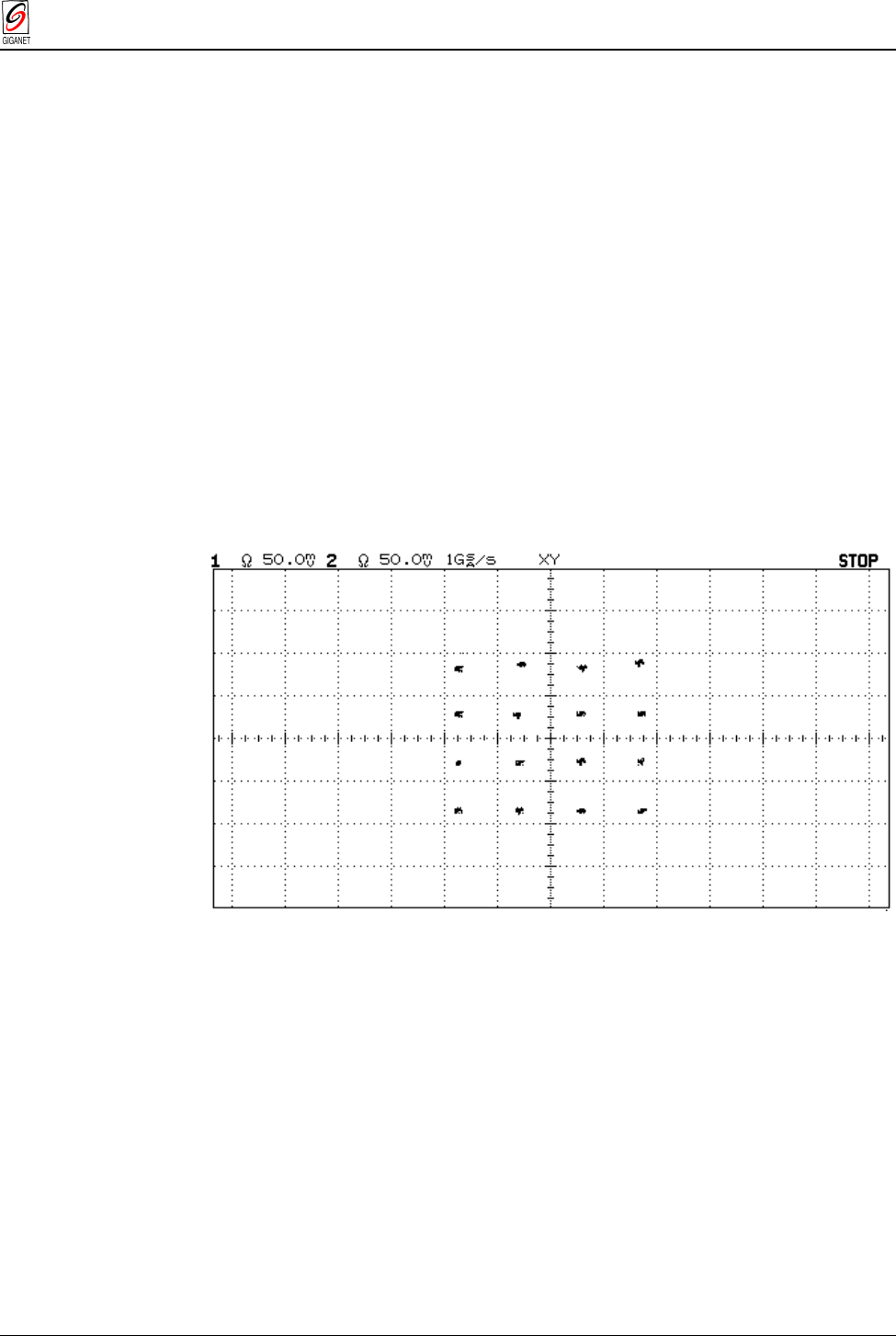
The FibeAir 1500 is equipped with a 16-states QAM Modem. The modem
delivers a 155 Mb/s payload in 50/56 MHz channel bandwidth in compliance
with FCC/ETSI standards. The Modem is equipped with Digital Signal
Processing functions as follows:
n Digital IF - I/Q modulator/demodulator whose functions are:
⇒ Conversion of the modulated signal to/from the IF frequency.
⇒ Automatic level equalization on the signal from ODU.
⇒ Protection against overloads.
n Timing recovery techniques employing digital tracking loop.
n FEC ensures unfaded BER lower than 10-13.
The following figure illustrates a measured 16 QAM constellation.
Figure 2-2 16 QAM Constellation
Chapter 2. Theory of Operation FibeAir 1500 Installation & Operation Manual
2-4 In Door Unit (IDU) Revision 2.0
2.2.3. Manager Module
The Manager module controls and manages all system’s modules, local
and remote units.
The Manager module also supports the user interface through Ethernet or
PPP/SLIP to the management station, and an ASCII terminal port. A local or
dumb terminal can be used for basic configuration and performance
monitoring.
Other features include:
n Log file.
n Remote software and firmware download (upgrades can be
downloaded from local to remote).
n Performance monitoring.
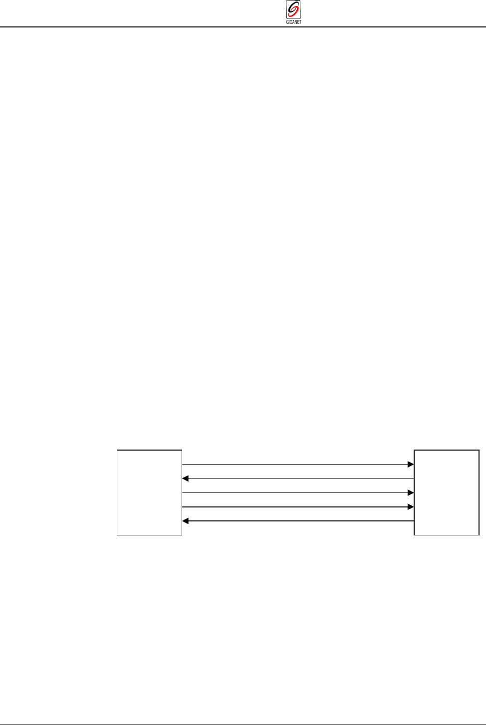
2.2.4. Cable Interfaces
A single coaxial cable connects the IDU to the ODU. This cable carries the
following signals:
n Transmit and receive modulated signals.
n Transmit and receive control data and communications between the
IDU manager and the ODU controller.
n DC power from the IDU to the ODU.
The system automatically issues an alarm if the cable is disconnected and
provides protection against shorts. Furthermore, there is no need to
measure and define the length and type of cable used since the system
automatically compensates cable parameters.
The following figure illustrates the signal direction through the coaxial cable.
-48 VDC
ODU TO IDU (CONTROL)
IDU TO ODU (CONTROL)
TX (PAYLOAD 155M)
RX (PAYLOAD 155M)
Figure 2-3 Signal Direction Through the Coaxial Cable

FibeAir 1500 Installation & Operation Manual Chapter 2. Theory of Operation
Revision 2.0 Out Door Unit (ODU) 2-5
2.2.5. Power Supplies
The power supply features:
n Standard Input : -48VDC
n DC input range : -40.5VDC to –72VDC
n DC/DC converter.
n Reverse polarity protection.
n Over-voltage and over-current protection.
n Detection of IDU-ODU cable alarms (i.e. cable open, cable short).
The ODU receives its DC power from the IDU. The PWR LED on the front
panel of the IDU continuously lights to indicate the existence of input
voltage.
2.3. Out Door Unit (ODU)
The ODU is designed to be fastened to the antenna using four latches. The
antenna is mounted on a standard mounting pole. The ODU is enclosed in a
compact, weather proof enclosure and connects to the IDU via a single
coaxial cable that can extend up to 300m (1000 ft).
The ODU major modules:
n T/R Module – A high sensitivity RF circuitry with full band frequency
tuning range.
n Controller – Controls the ODU and provides ODU status signals, and
accurate received signal level (RSL) reading (in dBm).
n Cable Combiner – Detailed in paragraph 2.2.4.
n Power Supply - Detailed in paragraph 2.2.5.
Figure 2-4 ODU Mounted on the Antenna
Latches

Chapter 2. Theory of Operation FibeAir 1500 Installation & Operation Manual
2-6 System Specifications Revision 2.0
2.4. System Specifications
2.4.1. General
18 GHz 23 GHz 26 GHz 28 GHz 38 GHz
Standards FCC/ETSI FCC/ETSI ETSI FCC/ETSI/
Canada FCC/ETSI
Operating
frequency range 17.7 - 19.7
GHz 21.2 - 23.6
GHz 24.5 - 26.5
GHz 27.5 - 28.35 GHz /
27.5 - 29.5GHz/
27.35 - 28.35 GHz
37 - 38.4, 38.6-40 GHz/
37-39.5 GHz
Tx/Rx spacing 1560/1010
MHz 1200/1008
MHz 1008 MHz 450/1008/500 MHz 700/1260 MHz
RF channel
spacing 50/55/80
MHz 50/56 MHz 56 MHz 50/56 MHz 50/56 Mhz
Capacity OC-3/STM-1 or equivalent
Modulation type 16 QAM
Frequency
stability +/- 0.0005%
Frequency
source Synthesizer
RF channel
selection Via NMS
System
configurations Non-Protected (1+0), Protected (1+1)
2.4.2. Frequency
Frequency Supported Standards
18 GHz EN 300 430, CEPT T/R12-03, ITU-R F.595-5, FCC parts 15, 101
(formerly parts 21, 94)
23 GHz EN 300 198, BAPT 211 ZV 02/23, MPT 1409, CEPT T/R13-02, ITU-R REC.
F.637-2, FCC parts 15,101 (formerly parts 21,94)
26 GHz EN 300 431, BAPT 211 ZV 11/26, MPT 1420, CEPT T/R13-02, ITU-R REC.748-2
28 GHz EN 300 431, CEPT T/R13-02, ITU-R REC.748, FCC parts 15, 101
(formerly parts 21, 94)
38 GHz EN 300 197, BAPT 211 ZV 12/38, MPT 1714, CEPT T/R12-01, ITU-R REC.749,
FCC parts 15,101 (formerly parts 21,94), FCC: NZ4 GNT-FA-1500-38

FibeAir 1500 Installation & Operation Manual Chapter 2. Theory of Operation
Revision 2.0 System Specifications 2-7
2.4.3. Radio
18 GHz 23 GHz 26 GHz 28 GHz 38 GHz
Transmitted
Power 22 dBm 20 dBm 20 dBm 20 dBm 15 dBm
Tx
Attenuation
Range
30 dB 30 dB 30 dB 30 dB 25 dB
Receiver
Sensitivity
(BER=10-6 )
-73 dBm -72 dBm -72 dBm - 72 dBm -70 dBm
Receiver
Overload
(BER=10-6 )
Better than –15 dBm
Unfaded
BER Better than 10-13
2.4.4. Antenna
18 GHz 23 GHz 26 GHz 28 GHz 38 GHz
1 Ft Gain 33.5 dBi 35 dBi 36 dBi 36.6 dBi 39 dBi
2 Ft Gain 38.5 dBi 40 dBi 41 dBi 41.5 dBi 44 dBi
3 Ft Gain 42 dBi 43.5 dBi 44.5 dBi --------- ---------
4/6 Ft Gain 44.5/48 dBi 46/49.5 dBi 47 dBi --------- ---------
Polarization Vertical or Horizontal
Standard
Mounting OD
Pole
51mm – 114mm/2.0”-4.5” (Subject to vendor and antenna size)
High
Performance ETSI class 2, 3

Chapter 2. Theory of Operation FibeAir 1500 Installation & Operation Manual
2-8 System Specifications Revision 2.0
2.4.5. Payload
155.52 Mb/s Main Channel
Payload Types Sonet/SDH: OC-3/sts-3, OC-3c/STS-3c, SDH: OC-3/STM-1, ATM over Sonet/SDH,
IP over Sonet/SDH, 3xDS3/ES3, 3xE3
Physical Interfaces Electrical: CMI, UTP, STP, optical: single-mode, multi-mode, long-haul and short-haul
Compatible
Standards ITU-T G.703, G.707, G.783, G.823, G.957, G.958, ITU-T I.432, ATM Forum, ETSI
ETS 300 147, ETS 300 417, ANSI T1.105, ANSI T1.102-1993, Bellcore GR-253-core,
TR-NWT-000499
1544/2048 Kb/s Wayside Channel
Available
Interfaces T1/E1, Ethernet bridge 10Base-T, V.35, X21, RS-530 or V.36
64 Kb/s User Channel
Available
Interfaces 24 (RS-232, DB9, 64 Kb/s synchronous, 19.2 Kb/s asynchronous), or Ethernet bridge
10Base-T
Service Channel
Engineering Order
Wire ADM CVSD audio channel (64 Kb/s)
Note
:
All interfaces for Main and Wayside Channels are available via modular, plug-in interface units.
* 3xDS3/ES3 model is provided with a V.24 (RS232, DB9) user channel

FibeAir 1500 Installation & Operation Manual Chapter 2. Theory of Operation
Revision 2.0 System Specifications 2-9
2.4.6. Network Management, Diagnostics, Status and Alarms
Type SNMP, in compliance with RFC 1213, RFC 1595 (Sonet MIB)
Local or Remote
NMS Station GiganetViewTM with advanced GUI for Windows 95/98/NTTM or UNIXTM ,
integrated with HP OpenViewTM
NMS Interface Ethernet bridge 10Base-T, RS-232 (PPP, SLIP)
Local Configuration
and Monitoring Standard ASCII terminal, serial RS-232
Cascaded Topology Internal IP routing allows cascaded link topology
TMN Giganet NMS functions are in accordance with ITU-T recommendations for TMN.
Interconnection to TMN is available via Q3 interface upon specific requirement
External Alarms 8 Inputs, TTL-level or contact closure to ground, 5 Outputs, Form C contacts,
software configurable
RSL Indication Accurate power reading (dBm) available at IDU, ODU and NMS
Performance
Monitoring Integral with an on board memory per ITU-TG.826
2.4.7. Environmental
Operating Temperature
(Guaranteed Performance) ODU: -35oC to 55oC
IDU: -5oC to 45oC
Relative Humidity ODU: up to 100% (all weather operation)
IDU: up to 95% (non-condensing)
Altitude Up to 4,500m (15,000 ft)
2.4.8. Power
Standard Input -48V DC
DC Input range -40.5 to –72V DC
Optional Input AC
2.4.9. Mechanical Dimensions
ODU 25 cm diameter x 20/23 cm depth
(10” diameter x 8” depth)
8.45 kg weight
IDU 4.3 cm height x 43.2 cm width x 24.0 cm depth
(1.7” x 17” x 9.4”)
2.7 kg weight
IDU – ODU Coaxial Cable RG-223 (100 m/300 ft), Belden 9914/RG-8 (300 m/1000 ft)
or equivalent, N-type connectors (male)