Ceragon Networks GNT-FA1500-28 Point-to-Point digital radio User Manual FibeAir cover
Ceragon Networks Ltd. Point-to-Point digital radio FibeAir cover
Contents
- 1. chapter 4
- 2. chapter 5
- 3. chapter 2
- 4. chapter 3
chapter 5

Revision 2.0 General 5-1
5.1. General
This chapter explains in detail how to operate the GiganetView
management software and operate, configure and monitor the FibeAir 1500.
5.2. Logging In
To log into the GiganetView management software follow these steps:
1. Select Start ½ Program ½ GiganetView.
The Login window is displayed.
Figure 5-1 Login window

Chapter 5. Operation FibeAir 1500 Installation & Operation Manual
5-2 The Work Area Window Revision 2.0
To log in, enter your password and click OK.
There are two types of passwords, each with a different security level and
authorized activities:
Read only
–
System Operator
permitted to perform monitoring activities
only.
Read/write - Super User
permitted to change system configuration,
System Administrator
parameters and perform monitoring
activities.
The initial factory-set read/write password is giganet.
After logging in, the Work Area and Physical View windows are displayed
(see section 3.3 and 3.4 for details).
5.3. The Work Area Window
The Work Area window is your starting point for all operations. Below is a
description of the menus, toolbars and other features of the Work Area
window.
Figure 5-2 Work Area Window

FibeAir 1500 Installation & Operation Manual Chapter 5. Operation
Revision 2.0 The Work Area Window 5-3
5.3.1. Title Bar
The title bar of the Work Area window displays the following information:
Figure 5-3 Title Bar
Note that the "name of terminal" is user-defined via the General Information
window (Configuration ½ System Information). See section 4.4 for
details.
Closing the Working Area window by clicking on the "close window" button,
on the right side of the title bar is tantamount to logging out of the system.
5.3.2. Menu Bar
The menu bar of the Work Area window allows you to select options from
six menus.
Figure 5-4 Menu Bar
Below is a list of the various menus and the options they offer:
Figure 5-5 File Menu
Figure 5-6 Configurations Menu
FibeAir
Logo Name of
terminal Name of
window Minimize
window Close window
(Log off)

Chapter 5. Operation FibeAir 1500 Installation & Operation Manual
5-4 The Work Area Window Revision 2.0
Figure 5-7 Alarm Menu
Figure 5-8 Statistics Menu
Figure 5-9 Maintenance Menu
5.3.3. Toolbars
The Work Area window has four toolbars:
■ a general toolbar horizontally laid out directly below the menu bar
■ an ODU toolbar below the File menu option
■ an IDU toolbar
■ a Sonet/SDH toolbar.

FibeAir 1500 Installation & Operation Manual Chapter 5. Operation
Revision 2.0 The Work Area Window 5-5
General Toolbar
Key Explanation
General Information
− view and define system parameters such as link
definitions, contacts, system up time and IDU and ODU serial numbers.
System Configuration
− view and define general settings such as Local
Device Communications, managers list and the alarms reported to them.
Set Frequency
− define the frequency of the local and remote units.
Maintenance
− perform loopbacks and insert alarm signals.
Local RSL Monitoring
− attain a graph of the local received signal level.
Remote RSL Monitoring
− attain a graph of the remote received signal level.
Key Explanation
Alarm Status
− view the current alarm status.
Alarm Log File
− view the log file.
Help
− starts the online help system.
ODU Toolbar
ODU Configuration
− view and set up the radio link parameters.
Local RSL Statistics Monitoring
− view local received signal level data.
Remote RSL Statistics Monitoring
− view remote received signal level data.
IDU Toolbar
Local Unit Configuration
− define Local IDU parameters.
Remote Unit Configuration
− define Remote IDU parameters.

Chapter 5. Operation FibeAir 1500 Installation & Operation Manual
5-6 Physical View Revision 2.0
Sonet/SDH Toolbar
Sonet/SDH Configuration
− view and configure Sonet/SDH parameters.
Local Sonet/SDH Performance Monitoring
− view
Sonet/SDH
performance
data of the Local unit.
Remote Sonet/SDH Performance Monitoring
− view
Sonet/SDH
performance data of the Remote unit.
5.4. Physical View
The Physical View window is constantly displayed after logging into the
FibeAir 1500 management program. It provides a real-time virtual display of
the IDU front panel. This window may be closed and reopened at any time.
The window is reopened by selecting File ½Physical View on the Work
Area window.
Figure 5-10 Physical View Window
Place the pointer over any item in the window and hold it there to view a
ToolTip description of the item. Also, the status bar on the bottom of the
window constantly displays the name of the currently selected item (e.g.,
LED Alarms, Power Switch).
The display of the LEDs on the Physical View window indicates the actual
real-time status of the LEDs on the front panel of the IDU. Note that there is
a slight delay between the changes on the front panel and the time that they
are displayed on the Physical View window.
The LEDs on the front panel indicate the status of a number of important
factors. For the most part, the following rule applies: Green indicates a
good state (OK), Yellow indicates a warning, and Red indicates a major
alarm or a severe malfunction. See Table 3-1, below, for details.

FibeAir 1500 Installation & Operation Manual Chapter 5. Operation
Revision 2.0 Physical View 5-7
Table 5-1 IDU LED Alarms
LED Name Color Description
Red Yellow Green*
“Power”XXRed - Problem with power supplies, system not functional.
“Future Use”
“Line”XX XRed - No input to main channel / High BER
Yellow – JO mismatch.
“Loss of
Frame”XX
Red – Radio did not recognize information frame
(radio link problem/radio LOF).
“BER”XX X
Red – radio BER higher than radio excessive error
threshold definition (please refer to Sonet/SDH
configuration screen).
Yellow – radio BER higher then radio signal degrade
threshold definition (please refer to Sonet/SDH
configuration screen).
“Loopback”XXRed – Loopback is active.
“Stand By”XX
Yellow – Protected configuration: This unit is currently
passive or Tx mute applied.
“Future Use”
“IDU”XX X
Red – Modem unlocked.
Yellow – High temperature / Fan problem.
“ODU”XX XRed – No link/ ODU Power/ ODU unlocked.
Yellow – Radio interference./ High temperature/ Rx/Tx out
of range.
“Cable”XXRed – RF Cable open / RF Cable Short.
“Remote”XX X
Red – No link / fault in remote unit (any red led in the
remote unit).
Yellow – Warning in remote unit (any yellow led in the
remote unit).
* Green
–
Normal

Chapter 5. Operation FibeAir 1500 Installation & Operation Manual
5-8 Windows and Menus Revision 2.0
5.5. Windows and Menus
The following sections describe the various operational windows of the
FibeAir 1500. The options offered on each window are explained and
operation instructions are given.
5.5.1. File Menu Options
Physical View
This option displays the Physical View window, a real-time virtual display of
the IDU front panel. By default, the Physical View window, along with the
Work Area window, is displayed after logging in to the FibeAir 1500
management software.
System Information
This option allows you to view and define general settings for the
FibeAir 1500.
1. Select Configuration ½ System Information in the Work Area window.
The General Information window is displayed.
Figure 5-11 General Information Window
2. In the Time field, enter the current time of day in HH:MM:SS format
(24 hour format).
3. In the Date field, select the month using the pull-down menu and enter
the day of the month and year.
The Description field is read-only. It displays a textual description of the
entity. This value includes the full name and identification of the system’s
hardware type, software operating system, and networking software.

FibeAir 1500 Installation & Operation Manual Chapter 5. Operation
Revision 2.0 Windows and Menus 5-9
The Object ID field is read-only. It displays the vendor’s authoritative
identification of the network management system contained in the entity.
4. (Optional) In the Name field, enter an administrative-assigned name for
this managed node (link). By convention, this is the node’s fully-qualified
domain name.
5. (Optional) In the Contact field, enter the name of a person to contact in
case of problems with the system, together with information on how to
contact this person.
6. (Optional) In the Location field, enter the actual physical location of the
node or agent (e.g., ‘telephone closet, 3rd floor’).
The System Up Time field (read-only) displays the time elapsed since
the system was powered.
The ODU Serial Number field (read-only) displays the serial number of
the ODU.
The IDU Serial Number field (read-only) displays the serial number of
the IDU.
7. Click Apply.
The definitions and settings determined in the General Information
window are saved.
8. Click Cancel.
The General Information window is closed.
Login
The Login option is used to change authorizations. This option may also be
used to lock the application without exiting. After selecting this option, you
are prompted for your password in a pop-up window. Enter your password
and click OK.
Exit
This option allows you to exit the FibeAir 1500 management software. This
is the same as clicking on the Close Window icon in the title bar. When this
option is selected, an "Are You Sure?" prompt is displayed. Click OK to exit
the software; click Cancel to return.

Chapter 5. Operation FibeAir 1500 Installation & Operation Manual
5-10 Windows and Menus Revision 2.0
5.5.2. Configuration
a) Setting Frequency
1. Select Configuration ½ Set frequency in the Work Area window.
The Frequency Plan window is displayed.
Figure 5-12 Frequency Plan Window
At the top of the window, the system displays Tx/Rx frequency ranges and
the gap between them according to the appropriate standard (FCC or
ETSI), the type of ODU installed, and the channel bandwidth.
2. In the Frequency Control section, set the TX Channel to the required
channel. The corresponding frequency is displayed. By default, it is set
to the first channel. You can type the Tx frequency directly in Tx
Frequency field.
If you are unsure of the required channel, refer to Appendix E for FCC or
ETSI channel allocations.
3. Select the Local + Remote option (radio button should be filled ♦).
By default, the Local + Remote option is selected. This option applies
the TX Channel setting you make to both the local and remote units.
This step requires established remote connection.
4. Click Apply.
The settings are saved. From this point on, the ODU is set to the desired
frequency.
5. Click Cancel.
The Frequency Plan window is closed.
FibeAir 1500 Installation & Operation Manual Chapter 5. Operation
Revision 2.0 Windows and Menus 5-11
b) ODU Configuration
1. Select Configuration ½ ODU in the Work Area window.
The ODU Configuration window is displayed.
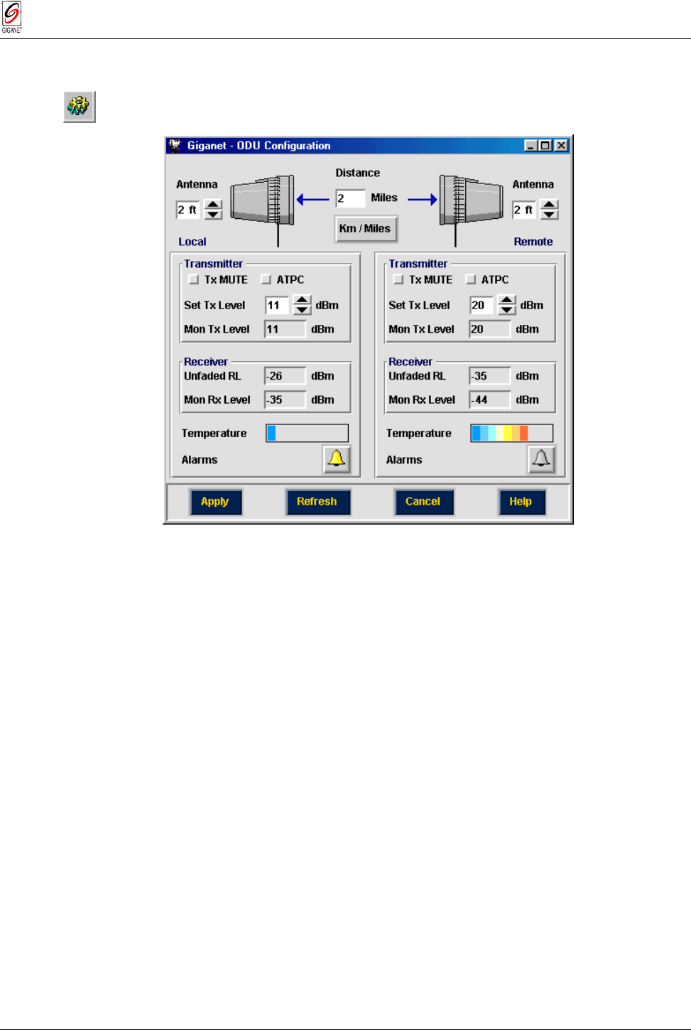
Figure 5-13 ODU Configuration Window
2. In the top center of the window, enter the distance between the local
and the remote antennas.
Perform the following steps for both the local and remote units (on
the left and right sides of the window):
3. In the top of the window, select the diameter of the antenna (1, 2, 4, or 6
feet). The default value is 1 foot.
Note
: Steps 2 and 3 required for calculating appropriate unfaded RL.
4. (Optional) In the Transmitter section, click on the Tx MUTE option to
block transmission to the remote unit. By default, this option is not
selected.
5. Click the ATPC option to enable Automatic Transmit Power Control
(ATPC) mode. By default, this option is not selected.
When activating ATPC option two entries for local and remote Rx levels
are displayed. The system’s power transmission levels are set to
achieve appropriate Rx levels, as entered by the user.
6. In the Set Tx Level fields, enter or select the designated signal level.
Possible range: -10 to max power level. By default, the transmit signal
level is set to the maximum power level (+15 ÷ +22dBm, according to
the frequency band). For more information, see Appendix E.

Chapter 5. Operation FibeAir 1500 Installation & Operation Manual
5-12 Windows and Menus Revision 2.0
The Mon Tx Level field (read-only) displays the system’s transmitted
power level.
The Mon Rx Level field (read-only) displays the received power level.
The unfaded Rx Level field displays the predicted receive level as
calculated from the distance and the antenna size.
The temperature scale shows the temperature of the ODU units, ranging
from blue (cold) to red (hot).
The color of the icon indicates the severity of the most severe
alarm currently triggered (if any). Click on the icon to view the current
alarm list.
7. Click Apply to store current window settings.
8. Click Cancel.
The ODU Configuration window is closed.
c) IDU Configuration
1. To define IDU Configuration select Configuration ½ IDU in the Work
Area window. The IDU Configuration window is displayed.
Figure 5-14 IDU Configuration Window
Follow the steps below for both the Local and Remote sides.

FibeAir 1500 Installation & Operation Manual Chapter 5. Operation
Revision 2.0 Windows and Menus 5-13
Setting External Alarm Inputs
The microcontroller in the IDU reads the alarm inputs (dry contact) and
transmits them over the management channel to the GiganetView
management system. This allows the FibeAir 1500 system to report external
alarms not related to itself.
For each alarm:
1. Click on the box next to the alarm number to enable/disable the alarm.
Alarms that are enabled are indicated by a filled red box (■); disabled
alarms are indicated by an empty box ( ).
2. Place the cursor in the field to the right of the enable/disable button and
type a description for the alarm (e.g., "door open", "A/C Failure").
3. Select a severity (Major, Minor, Warning or Event) for the alarm.
Setting Alarm Outputs
The FibeAir 1500 provides five alarm outputs, which may be used by other
systems to sense FibeAir 1500 alarms.
Figure 5-15 Setting Alarm Outputs
The alarm outputs are Form C Relays. Three pins are provided for each
alarm:
Normally open (NO)
Normally Closed (NC)
Common (C).

Chapter 5. Operation FibeAir 1500 Installation & Operation Manual
5-14 Windows and Menus Revision 2.0
Any output alarm may be defined as any one of the following:
Major Minor
Loopback Power
IDU ODU
Cable Remote
Signal Degrade Line
External
The default alarm output settings are:
Relay 1: On-Line (Power)
Relay 2: IDU
Relay 3: ODU
Relay 4: CBL (Cable)
Relay 5: RMT (Remote)
These relays may be connected to customer-specific applications. Refer to
Appendix B for details on the alarm connector pin assignments.
IDU Temperature and Alarms
The temperature scale shows the temperature of the IDU unit ranging from
blue (cold) to red (hot).
The color of the icon indicates the severity of the most severe alarm
currently triggered (if any). Click on the icon to view the current alarm list.
4. Click Apply to store current window settings.
5. Click Cancel.
The ODU Configuration window is closed.

FibeAir 1500 Installation & Operation Manual Chapter 5. Operation
Revision 2.0 Windows and Menus 5-15
d) Sonet/SDH Configuration
1. To define Sonet/SDH Configuration, select Configuration ½
Sonet/SDH in the Work Area window. The Sonet/SDH Configuration
window is displayed.
Figure 5-16 Sonet/SDH Configuration Window
Radio BER Alarm Thresholds (Optional):
2. In the Radio Excessive Error Thresh field, select the level above which
an Excessive BER alarm is issued for errors detected over the radio link.
3. In the Radio Signal Degrade Thresh field, select the level above which a
Signal Degrade alarm is issued for errors detected over the radio link.
Line Parameters (Optional):
4. In the Line Excessive Error Thresh field, select the level above which an
Excessive BER alarm is issued for errors detected on the line input.
5. In the Line Signal Degrade Thresh field, select the level above which a
Signal Degrade alarm is issued for errors detected on the line input.
Regenerator Section Overhead (RSOH) Function Parameters
(Required):
This section of the window allows you to determine the RSOH parameters,
which will be used.
6. Set each RSOH parameter that will be used as
active
and leave the
others set as
passthrough
.
By default, these parameters are set to
passthrough.
EOW – Engineering Order Wire.

Chapter 5. Operation FibeAir 1500 Installation & Operation Manual
5-16 Windows and Menus Revision 2.0
End to end voice channel option – E1 byte at the SDH RSOH –
activate/passthrough.
User channel – The 64 kbps user channel – F1 byte at the SDH RSOH
– activate/passthrough
E1 wayside – enable/disable the wayside channel.
JO operation – JO byte is used as a trace identifier at the SDH RSOH.
If JO is activated, use the “Tx JO” and “Exp JO” to define IDU identifier
string and “AIS” mode of operation.
DCCR – activate/passthrough the RSOH communication channel
normally used for inband TMN.
B1 operation – activate/passthrough B1 byte at the RSOH. B1 is used
to perform parity byte checks for monitoring SDH quality and service.
7. Click Apply.
The definitions and settings determined in the SDH Configuration
window are saved.
8. Click Cancel.
The SDH Configuration window is closed.
e) System Settings
1. Select Configuration ½ System Settings in the Work Area window.
The System configuration window is displayed.
Figure 5-17 System Configuration Window
The System Configuration window is divided into three sections:
■ Local Device Communication Parameters
■ Managers List
■ Alarm Groups.

FibeAir 1500 Installation & Operation Manual Chapter 5. Operation
Revision 2.0 Windows and Menus 5-17
Setting Local Device Communication Parameters
Figure 5-18 Local Device Communication Parameters
1. In the
SLIP IP Address
field, set the SLIP IP Address column to zeros.
For further information regarding serial communications, please refer to
sections 4.2.7 – 4.2.9 and to Appendix D.
2. (Optional) In the
SLIP Modem phone number
field, enter the phone
number to be dialed by the IDU when traps are issued..
3. In the
Baud Rate
field, select the baud rate of your modem.
The baud rate of the NMS terminal and the FibeAir 1500 system must
match in order to provide a valid connection between the NMS terminal and
the IDU. By default, the IDU’s baud rate is set at 19,200. For details on how
to set the PC baud rate, refer to section 3.9.7.
Defining the Managers List
The Managers List section of the System Configuration window allows you
to define up to three managers to whom the systems alarms will be sent.
Figure 5-19 Managers List
Enter the IP addresses of up to three system managers.

Chapter 5. Operation FibeAir 1500 Installation & Operation Manual
5-18 Windows and Menus Revision 2.0
Defining Alarm Groups
The Alarm Groups section of the System Configuration window allows you
to determine which alarms are reported to each manager.
1. In the column of each manager, click on the types of alarms you want to
report to that manager.
Figure 5-20 Alarm Group Window
2. Click Apply.
The definitions and settings determined in the System Configuration
window are saved.
3. Click Cancel. The System Configuration window closes.

FibeAir 1500 Installation & Operation Manual Chapter 5. Operation
Revision 2.0 Windows and Menus 5-19
5.5.3. Alarms
Viewing Alarm Status
To view the status of the alarms select Alarms ½ Alarms Status in the
Work Area window. The Alarms window is displayed.
Figure 5-21 Alarms Window
Each line in the window describes a different alarm. On the left, an icon of
the faulty unit (IDU, ODU or MUX) is displayed. The color of the icon
indicates the severity of the alarm:
Red Major alarm
Orange Minor alarm
Yellow Warning
Blue Event
The alarms related to the Local unit are displayed on the left side of the
window. The alarms related to the Remote unit are displayed on the right
side.
The alarms displayed are sorted in two ways. First, they are sorted
according to severity and then they are sorted by type of faulty unit (MUX
first, then ODU and then IDU).

Chapter 5. Operation FibeAir 1500 Installation & Operation Manual
5-20 Windows and Menus Revision 2.0
Viewing the Alarm Log File
To view the alarm log file, follow these steps:
1. Select Alarms ½ View Log File.
The Alarm Log File window is displayed.
Figure 5-22 Alarm Log File Window
When the system reaches 80% capacity, it automatically saves the current
alarms in a log file. These files are stored in the following directory:
C:\GIGANETVIEW\LOG
where C:\GIGANETVIEW is the directory in which you installed the Giganet
View software.
The Alarm Log File window displays the following information:
Date The date the alarm was triggered.
Time The time the alarm was triggered.
Severity The severity of the alarm.
Alarm
Description A description of the alarm.
Saving a Log File
To save a log file as an ASCII file, click on the Save button. The file is
saved in the same directory where GigaView software installed, as
described above.

FibeAir 1500 Installation & Operation Manual Chapter 5. Operation
Revision 2.0 Windows and Menus 5-21
5.5.4. Statistics Menu Options
RSL Monitoring
1. Select Statistics ½ RSL Monitoring in the Work Area window.
The RSL Monitoring window is displayed.
Figure 5-23 Local RSL Monitoring Window
Figure 5-24 Remote RSL Monitoring Window
The RSL Monitoring windows display the current received signal level
status and values for both the Local unit (top of screen) and Remote unit
(bottom of screen):
The RX LEVEL field displays the current receive signal level.
The Line BER field displays the current Bit Error Rate of the line.
The Radio BER field displays the current Bit Error Rate of the radio.
The Unfaded RL field displays the expected receive signal level.
Note
: If there is no communication between the local and remote units, the Remote RSL
Monitoring window will not be available.

Chapter 5. Operation FibeAir 1500 Installation & Operation Manual
5-22 Windows and Menus Revision 2.0
The Received Signal Level graphs show the received signal level over the
past hour.
2. Click on Cancel.
The RSL Monitoring window is closed and you are returned to the Work
Area window.
RSL Statistic Monitoring
The RSL Statistic Monitoring window displays the RSL values measure over
the past 24 hours.
1. Select Statistics ½ RSL Statistic Monitoring in the Work Area window.
The RSL Statistic Monitoring window is displayed.
Figure 5-25 RSL Statistic Monitoring Window
Figure 5-26 Remote RSL Statistic Monitoring Window
Note
: If there is no communication between the local and remote units, the Remote RSL
Statistics window will not be available.

FibeAir 1500 Installation & Operation Manual Chapter 5. Operation
Revision 2.0 Windows and Menus 5-23
2. Click on the History button to open the RSL Local/Remote Performance
History window.
Figure 5-27 Local RSL Performance
History Window Figure 5-28 Remote RSL
Performance History Window
The
Local RSL 24 Hour History
and the
Remote RSL 24 Hour History
sections display the following details about the radio signal over the last 24
hours for the local unit and remote unit, respectively:
Int the time interval in which the measurement was made
Time the actual time when the measurement was made (according
to the internal IDU clock).
Min RL the minimum received level measured during the interval
Max RL the maximum received level measured during the interval
The
Local RSL Day History
and the
Remote RSL Day History
sections
display the following details about the radio signal over the last month for
the local unit and remote unit, respectively:
Date the date in which the measurement was made (according to
the internal IDU clock)
Min RL the minimum received level measured during the date above
Max RL the maximum received level measured during the date above
Note
: If there is no communication betweeen the local and remote units, the Remote
Performance History window will not be available.
Chapter 5. Operation FibeAir 1500 Installation & Operation Manual
5-24 Windows and Menus Revision 2.0
SDH Performance Monitoring
There are two SDH Performance Monitoring options: Local and Remote.
Select the unit you are interested in and follow the steps below.
1. To view SDH Performance Monitoring screen, select Statistics ½
SDH Performance Monitoring ½ Local/Remote in the Work Area
window. The SDH Local/Remote Performance Monitoring window is
displayed.
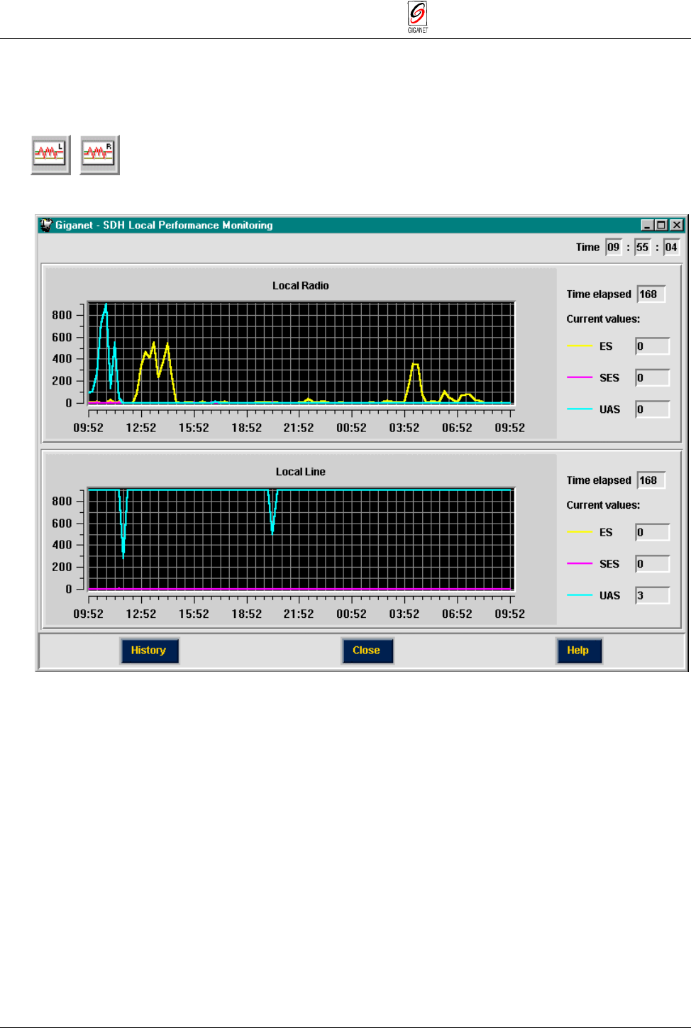
Figure 5-29 SDH Local Performance Monitoring
The SDH Local/Remote Performance Monitoring window displays the signal
level measured every 15 minutes over the last 24 hours. The window is split
into two sections: the top section displays the Local Radio monitoring data
and the bottom section displays the Remote Line monitoring data.
Each section displays the following details:
The Time Elapsed field displays the number of seconds since the current
monitoring period commenced.
The ES field displays the number of errored seconds in the period that
elapsed.
The SES field displays the number of severely errored seconds in the
period that elapsed.
The UAS field displays the number of unavailable seconds in the period that
elapsed.
FibeAir 1500 Installation & Operation Manual Chapter 5. Operation
Revision 2.0 Windows and Menus 5-25
2. Click on the History button to open the Sonet/SDH Local/Remote
Performance History window.
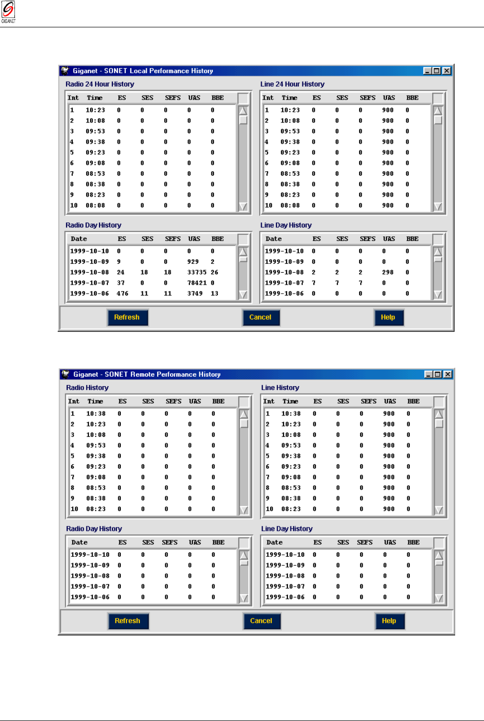
Figure 5-30 SDH Local Performance History Window
Figure 5-31 SDH Remote Performance History Window
Note
: If there is no communication betweeen the local and remote units, the SDH Remote
Performance History window will not be available.

Chapter 5. Operation FibeAir 1500 Installation & Operation Manual
5-26 Windows and Menus Revision 2.0
The SDH Local/Remote Performance History window displays details
related to the SDH performance of the local or remote unit. It is divided into
four sections:
Radio 24 Hour History
− displays the following details about the radio
signal over the last 24 hours:
Int the time interval measurement serial number
Time the time interval in which the measurement was made
ES the number of errored seconds
SES the number of severely errored seconds
EFS the number of EFS – error free seconds
UAS the number of unavailable seconds
BBE the number of BBE – background block errors
Line 24 Hour History
− displays the following details about the line
signal over the last 24 hours:
Int the time interval measurement serial number
Time the time interval measurement was made
ES the number of errored seconds
SES the number of severely errored seconds
SEFS the number of SEFS – severely errored frame seconds
UAS the number of unavailable seconds
BBE the number of BBE – background block errors
Radio Day History
− displays the following details about the radio
signal over the last month:
Date the date measurement was made
ES the number of errored seconds
SES the number of severely errored seconds
SEFS the number of SEFS – severely errored frame seconds
UAS the number of unavailable seconds
BBE the number of BBE – background block errors
Line Day History
− displays the following details about the line
signal over the last month:
Date the date measurement was made
ES the number of errored seconds
SES the number of severely errored seconds
SEFS the number of SEFS – severely errored frame seconds
UAS the number of unavailable seconds
BBE the number of BBE – background block errors

FibeAir 1500 Installation & Operation Manual Chapter 5. Operation
Revision 2.0 Windows and Menus 5-27
5.5.5. Maintenance
Loopback
1. To perform loopback testing, select Maintenance ½ Loopback.
The Loopback window is displayed.
Figure 5-32 Loopback Window

Chapter 5. Operation FibeAir 1500 Installation & Operation Manual
5-28 Windows and Menus Revision 2.0
The Loopback window is divided into two sections:
Local
and
Remote
.
The Local section is detailed below.
Figure 5-33 Loopback Window - Local Section
Figure 5-34 Loopback Window - Remote Section
2. Define the tests you want to perform by using the test configuration
buttons. When a option button is pressed it is selected and displayed in
Red.
Select Force AIS to test SDH networks.
Select Force RDI to test networks.
For details on running loopback tests, see Chapter 6. System Maintenance.
Force AIS
to remote
To IDU
and back
Force AIS
to line
User
channel
Force RDI
to remote
Force RDI
to line
Remote to
local and
back
Line
Wayside
Force AIS
to local
Force AIS
to line
User
channel
Force RDI
to local
Force RDI
to line
Local to
remote
and back
Line
Wayside