Cernium AF3001000 Outdoor Low-Light Wireless Camera & Recording System User Manual CERTIFICATE OF COMPLIANCE
Cernium Corporation Outdoor Low-Light Wireless Camera & Recording System CERTIFICATE OF COMPLIANCE
Cernium >
User Manual

Rhein Tech Laboratories, Inc.
Client:
Cernium Corporation
360 Herndon Parkway
Model #:
AF3001000
Suite 1400
Standard:
FCC 15.247
Herndon, VA 20170
http://www.rheintech.com
FCC ID:
X86-AF3001000
Report #: 2010038
Page 50 of 65
Appendix H: Manual
Please refer to the following pages.

Table of Contents
Before You Start Make Sure You Have What You Need
Step 1 Add Solo to Your Wireless Router
Step 2 Assemble Solo
2-1 Assemble Mount Base for Ethernet (oponal)
Step 3 Install Solo
Welcome to Video Monitoring Done Right™. Archersh is the only smart, wireless security
camera and recorder that can understand what it sees and send video alerts when
important things happen. While the Geng Started with Archersh Solo insert provides
an overview, this guide takes you step-by-step to set up and personalize your Archersh
system.
For addional help or troubleshoong, contact Archersh Customer Support at
support@myarchersh.com or 877.3.THEFISH (877.384.3347). We’re available Monday –
Friday, 8 am – 8 pm Eastern Time. Online Help is available anyme at
www.myarchersh.com/solosetup.
Welcome
page 01Archersh Solo Installaon Guide
Page
02
03
06
08
09
11
13
14
15
16
17
18
19
20
21
22
23
24
25
Step 4 Register Solo
4-1 Register Primary User
4-2 Dene Nocaon Methods
4-3 Set Billing Preferences
4-4 Set Up Live Video
Step 5 Customize Your System
5-1 Set Up Zones
5-2 Congure Events
5-3 Dene Nocaon Methods by Camera
Now that You’re Done Using the Dashboard
Helpful Hints in Making Archersh Work for You
Appendix A: Port Forwarding Set Up
Appendix B: Solo Device LED Quick Reference
Noces
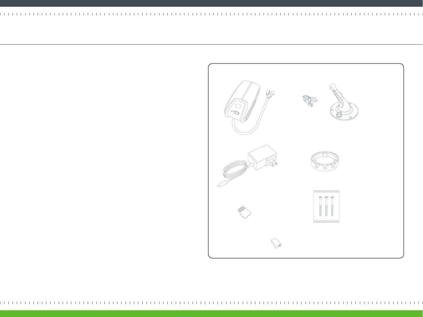
Your Archersh Solo comes with the items pictured in Figure 1.
Other things you’ll need to set up are:
- PC with Microso Internet Explorer (version 7.0 or 8.0) or Mozilla Firefox
(version 3.5 or higher)
- Acve broadband Internet connecon with an upload speed of at least
512 kbps
- Wireless router (with available port for inial setup) connected to the
Internet
- Phillips and sloed (“athead”) screwdrivers
Before You Start Make Sure You Have What You Need
page 02Archersh Solo Installaon Guide
Figure 1 Archersh Solo items
Archersh Solo Device
MicroSD Card
Archersh Solo Mount Base
Archersh Solo Mount with Rotang Joint
Archersh Solo Power Supply
Three Screws
Ethernet Adaptor (usually not needed)
Seng up wireless connecvity between Solo and your router is easy because
there’s an Archersh Solo Wi-Fi Wizard that does the work for you.
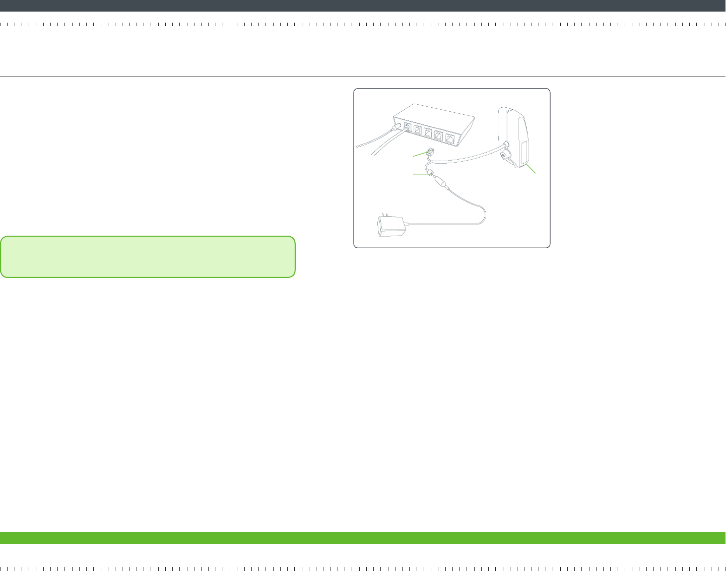
Before the Wizard can begin, you need to connect the Ethernet connector to
your wireless router and then connect the power connector to the power supply
(Figure 2).
Next, plug in the power supply.
Wait for the small LED light on the boom of Solo to turn green before
proceeding to the next page. It may take several minutes for the light to turn
green.
Note: The LED light on the Solo device uses dierent color and blink
paerns to tell you what it’s doing. For a summary of all the dierent LED
states, see Appendix B on page 24.
Step 1 Add Solo to Your Wireless Router
page 03Archersh Solo Installaon Guide
Figure 2 Solo device’s power and Ethernet connectors
Ethernet connector
power connector LED
Step 1 Add Solo to Your Wireless Router (continued)
page 04Archersh Solo Installaon Guide
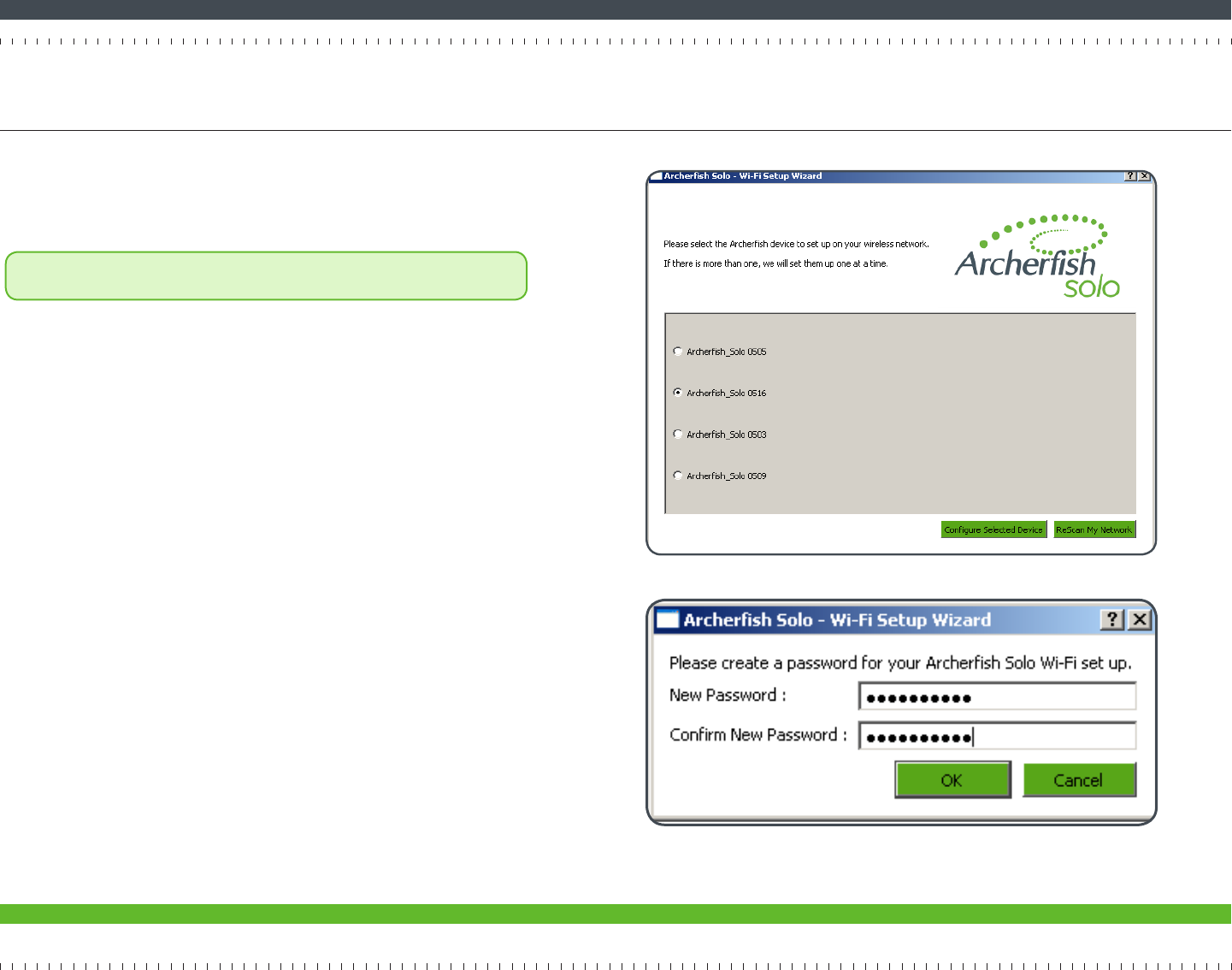
Figure 3 Archersh Devices detected by the Wi-Fi Setup Wizard
Figure 4 Creang a password for your Solo
On a PC, go to www.myarchersh.com/solosetup to download the Solo Wi-Fi
Setup Wizard. Make sure you’re saving the le (Solo_WIFI_Cong.exe) in the
same local network you plan to install Solo on. Double click the le to run it.
Note: If your Windows rewall or other security applicaon asks if you want
to run “SoloCongWizard” you’ll need to agree.
Once the Wizard has launched, click the Start buon.
The Wizard takes a few moments to detect all Solo devices that are connected to
your router.
Select the Solo device you wish to congure for Wi-Fi (Figure 3). If you have
mulple Solo devices, you can see which device is which by matching the four
digits displayed at the end of the Solo device name with the last four digits in the
device serial number (included in the Geng Started insert).
Click the Congure Selected Device buon.
Now you’ll need to provide and conrm a password for the Solo device (Figure
4). You’ll need this password if you ever need to go back and edit the device’s
Wi-Fi conguraon at a later me.
Click OK.
Step 1 Add Solo to Your Wireless Router (continued)
page 05Archersh Solo Installaon Guide
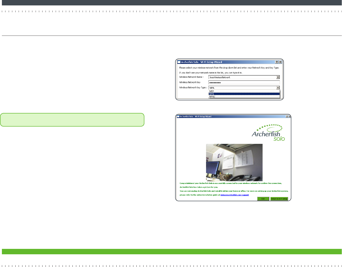
Next, you’ll be prompted for a Wireless Network Name, Wireless Network Key,
and Wireless Network Key Type (Figure 5).
The Wireless Network Name should be the name of your wireless router. The
Wireless Network Key is the password you use to access your router (it may
even be wrien on a label on your router). If you don’t have this informaon,
you may have to ask your service provider.
There are several available Wireless Network Key types, each corresponding to
a level of security. These include WPA (most commonly used), WPA2, and WEP.
If this eld is empty and you don’t know which type of network key your router
uses, you can test each one of these opons unl one of them works.
Note: If using WEP (e.g., you are a Verizon FiOS customer using your router’s
default sengs), you may need to click the Hex Key checkbox.
Click OK.
If the wireless connecvity is successfully established, the Wizard will display
a Congratulaons message and display a snapshot of whatever’s currently
in front of your Solo device (Figure 6). At this point, the LED light on the Solo
device will be green.
Before proceeding to the next step, disconnect both the Ethernet and power
connecons.
Figure 5 Wireless network sengs
Figure 6 Wi-Fi Setup Wizard compleon
Step 2 Assemble Solo
page 06Archersh Solo Installaon Guide
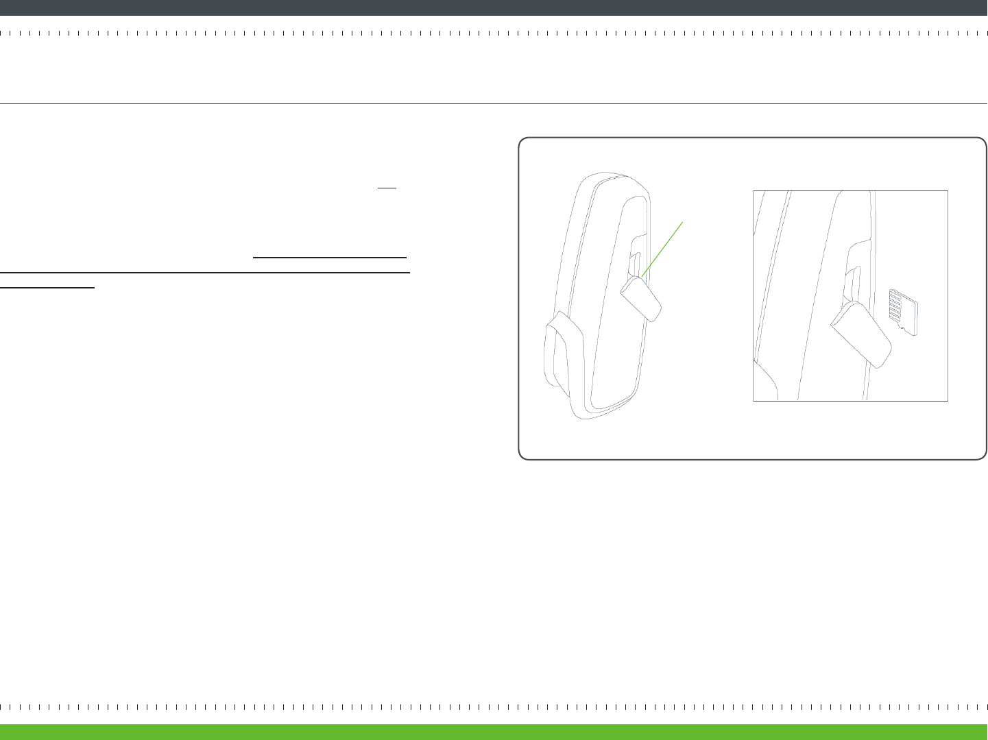
Figure 7 MicroSD card inserted into the Solo device
There are a few steps you need to perform to physically put Solo together,
including inserng a MicroSD card for recording and aaching the mount.
Before inserng the MicroSD card, make sure that the Solo device does not
have power.
Open the MicroSD slot cover (“door”) of the Solo device and insert the
MicroSD card into the card slot as shown in Figure 8. When inserng the card,
gently push it straight in unl it clicks into place. Be sure to insert it with the
underside of the card facing the front of the Solo device (“upside down”) as
shown in Figure 7. Close the door.
Now Solo will be able to record connuous video to the MicroSD card. Once
you’re done with the installaon process, you’ll be able to view this recorded
video on the Archersh SmartPortal.
door
Step 2 Assemble Solo (continued)
page 07Archersh Solo Installaon Guide
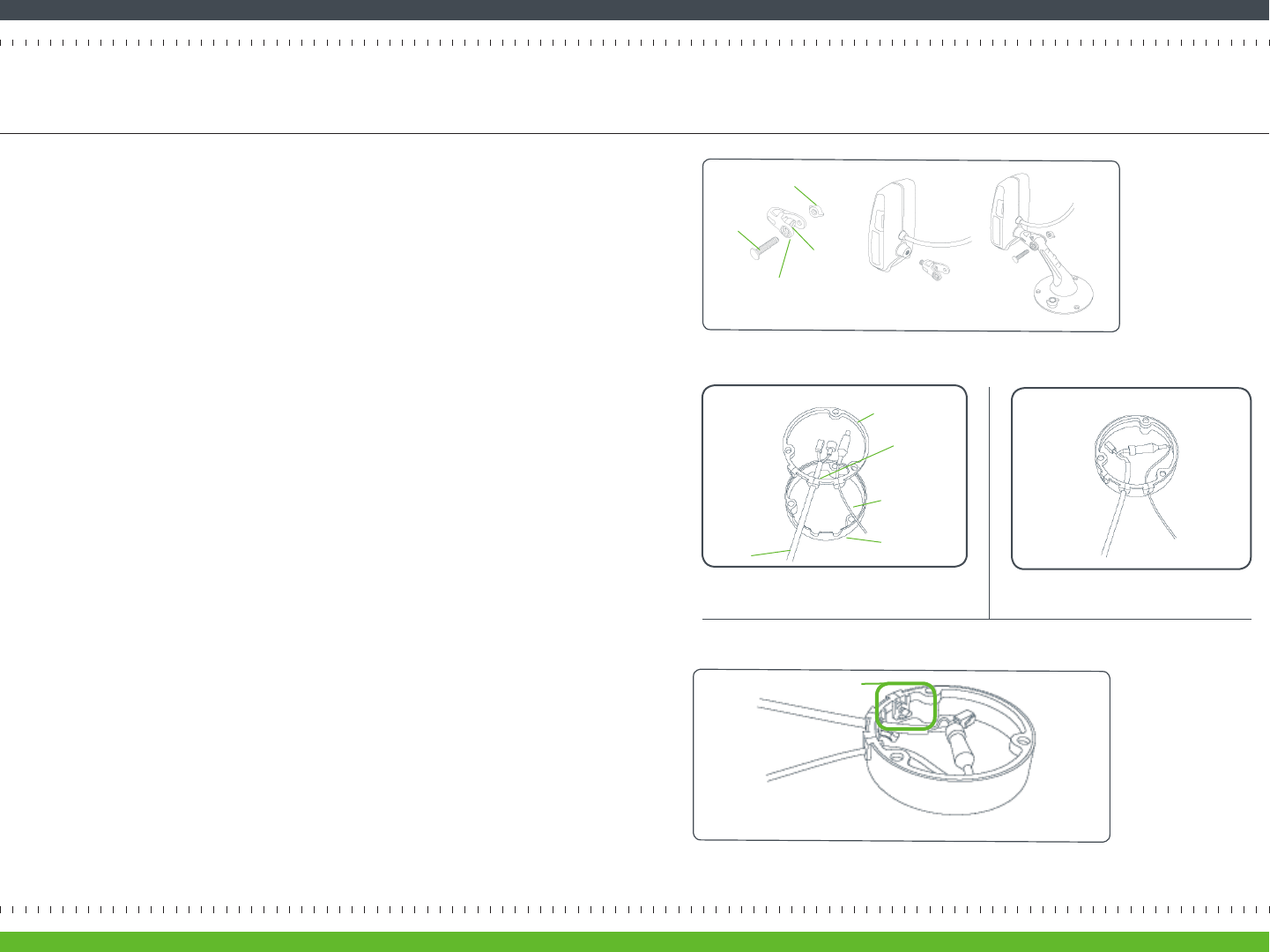
Figure 8 Aaching the Solo device to the mount with the rotang joint
The Solo device comes with a mount for installing it on a wall, ceiling, or shelf.
Aaching the device to its mount requires some basic assembly, illustrated in
Figure 8 on the right.
• First remove the nut and stud from the rotang joint to expose the screw
inside the rotang joint (Figure 8A).
• Using your sloed screwdriver, ghten the screw in order to aach the
rotang joint to Solo (Figure 8B)
• Finally, slide the mount arm into the rotang joint and secure the stud
into pace with the nut (Figure 8C). The head of the stud should reset in the
side of the rotang joint that is recessed.
Next, assemble the mount base. To connect the power cables within the mount
base, rst remove the Ethernet adapter from inside the mount base. Gently
pull the rubber gasket away from the base. Press the cable aached to Solo
down through the gasket’s le-hand slot and then press the power supply cable
down through the right-hand slot (Figure 9A). Connect the two cables inside
the base (Figure 9B).
You will aach the mount base to the mount when you screw the mount in
place (described on page 10).
If Solo is going to be wirelessly connected to the Internet, press the tab into
the center slot to close it (Figure 10) and then skip ahead to Step 3 on page 9.
If you will be using a cabled Ethernet connecon, proceed to Step 2-1 on the
next page.
Figure 9 Assembling the mount base
A How cables are placed into the mount
base’s rubber gasket
B Power cables connected within the
mount base
Figure 10 Unused le-hand slot, with tab
ABC
rubber gasket
center slot
power cable
mount base
cable aached
to Solo
empty slot and tab
rotang joint rotang joint
screw
nut
stud
Step 2-1 Assemble Mount Base for Ethernet (optional)
page 08Archersh Solo Installaon Guide
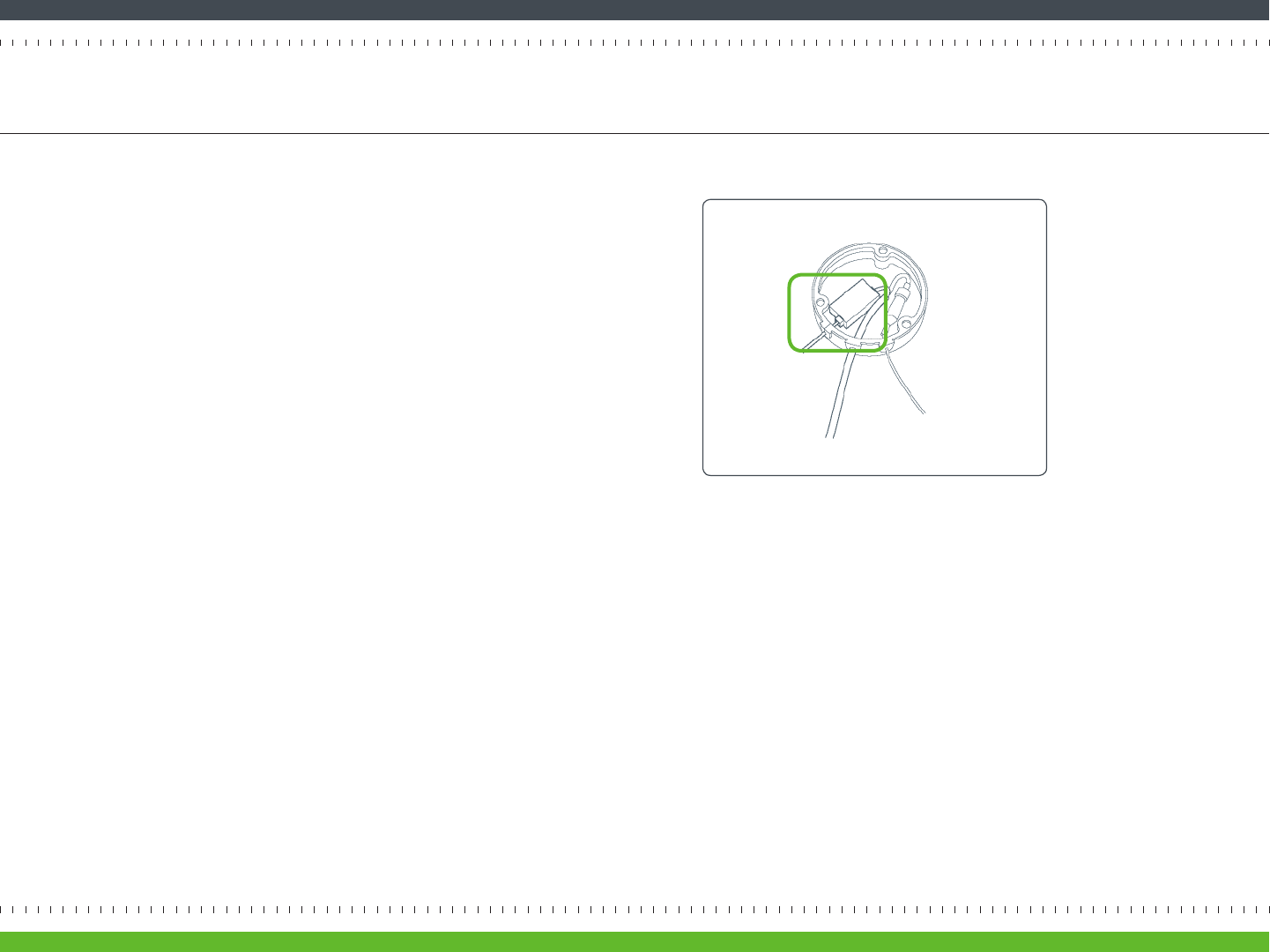
Figure 11 Ethernet cables connected via the Ethernet
adapter within the mount base
Although Solo is designed to work over a wireless network, you’re free to have
it permanently connected to your router over a dedicated Ethernet cable. In
such a case, you’ll need to have the Ethernet cable coming out of the Solo
device to connect to the Ethernet cable leading to your router.
If you followed the instrucons on the previous page, you’ve already placed
the Solo cable through the le-hand slot in the mount base and connected its
power connector to the power supply.
To connect the Solo cable’s Ethernet connector to the Ethernet cable leading
to your router, press the router’s Ethernet cable down through the center
slot. Then insert the Ethernet adaptor into the mount base and connect both
Ethernet connectors to either side (Figure 11).
Solo is a very smart and exible device, but you can help it work, and make your own
viewing experience beer, by installing Solo where it can have a clear view of the things
you want to see. So we recommend following these guidelines when you select a
locaon for your Archersh system.
DESCRIPTION ü
WI-FI
CONNECTIVITY
Conrm that the Solo device can receive a signal from your wireless
router. To do this, plug it into a nearby power outlet. If you see a
green light on the Solo LED within two minutes, there’s a wireless
signal.
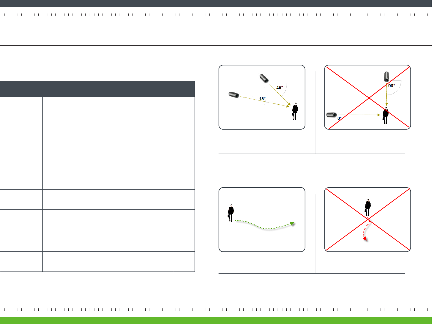
SOLO PLACEMENT Solo device should be installed 8 to 20 feet above the ground and
lted downward at an angle between 15° and 45° (Figure 12). It
should be posioned 10 to 40 feet from people, or 20 to 60 feet
from vehicles.
DIRECTION OF
MOTION
People and vehicles should normally move from le-to-right or right-
to-le in the camera view (Figure 13A), not directly toward or away
(Figure 13B).
IMAGE SHARPNESS Maintain a clear camera image. Don’t point the camera through a
window pane or screen, and avoid placing it in condions that would
cause the camera lens to fog up or accumulate water droplets.
CAMERA
ORIENTATION
Objects in the camera view should appear upright. In other words,
the Solo device should not be rotated clockwise or counter-clock-
wise.
SECURE MOUNTING Solo device should be securely mounted.
ADEQUATE, EVEN
LIGHTING
Lighng should be constant and sucient to read a newspaper in the
camera view where people or vehicles appear.
PHYSICAL
OBSTRUCTIONS
Physical obstrucons or sources of constant moon (e.g., moving
doors, ags waving in the wind, etc.) are not in the camera view.
REFLECTIONS,
GLARE, OTHER
LIGHTING EFFECTS
Reecve surfaces (e.g., mirrors, window panes, water, or polished
oors) or bright lights (e.g., headlight glare, direct sunlight) are not
directed at the camera.
Step 3 Install Solo
page 09Archersh Solo Installaon Guide
Figure 12 Camera Angle
A MORE EFFECTIVE - Cameras are at 15 to
45 degree downward lt
B LESS EFFECTIVE - Cameras are direct-
ly overhead (90 degrees) or parallel to
(0 degrees) the target
Figure 13 Target Direcon of Moon
A MORE EFFECTIVE - A target traveling from
le to right
B LESS EFFECTIVE - A target traveling
directly toward the camera
For more informaon and specic examples, go to www.myarchersh.com/solosetup
and review the Camera Placement Guide. At that site you can also watch a short video
on camera setup.
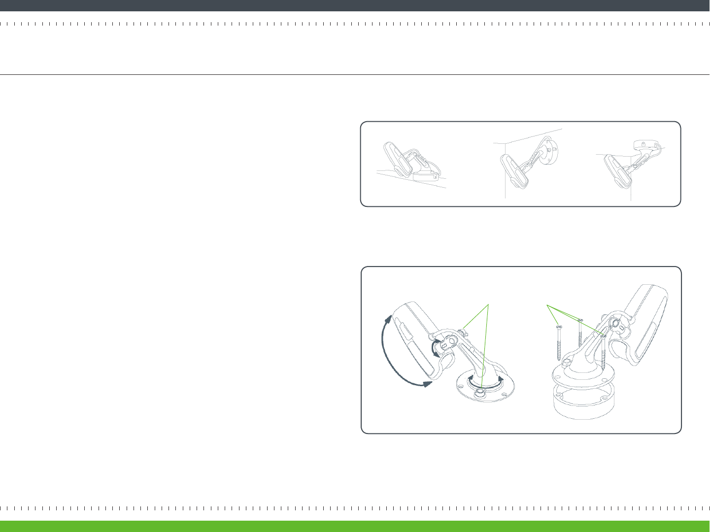
You can aach Solo to a ceiling, wall, or shelf as seen in Figure 14. Noce that
in each example the lens is pointed down at about a 45 degree angle.
Once the Solo device is assembled with its mount, you can adjust the direcon
Solo is pointed (Figure 15, le). To do so loosen a nut, change the Solo device
posion, and then re-ghten the nut. Then use the three screws to aach the
Solo mount to the desired surface. The screws must pass through both the
mount and mount base (see Figure 15, right).
Make sure that the cabling coming out of the mount base is pointed
downward.
Step 3 Install Solo (continued)
page 10Archersh Solo Installaon Guide
Figure 15 Adjustment nuts (le); using three screws to aach mount and mount base to surface
Figure 14 Shelf (le), wall (center), and ceiling (right) mounng posions
nuts screws
You’ll need to acvate your Archersh Solo by registering it. To do so, open an Internet
browser and sign in at portal.myarchersh.com/signup.
Note: If you already have an Archersh account and need to register
addional Archersh devices, do not go through the Inial Registraon
process. Instead, go to www.myarchersh.com, log in to the SmartPortal, and
then click on Devices > Add a Device.
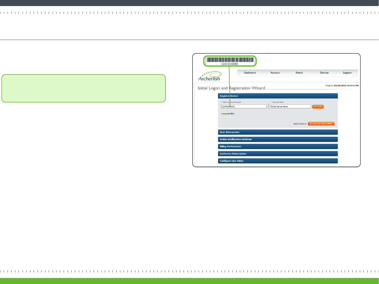
On the Inial Logon and Registraon Wizard page, you’ll need to enter the serial
number of your Solo (Figure 16). The serial number can be found in your Geng
Started with Archersh Solo insert. You may want to save this insert so you can have the
serial number for your records. If you no longer have the insert, the Serial number can
also be found on the tag aached to the Solo device’s power cable.
Step 4 Register Solo
page 11Archersh Solo Installaon Guide
Figure 16 Archersh device serial number in Device Serial Number eld
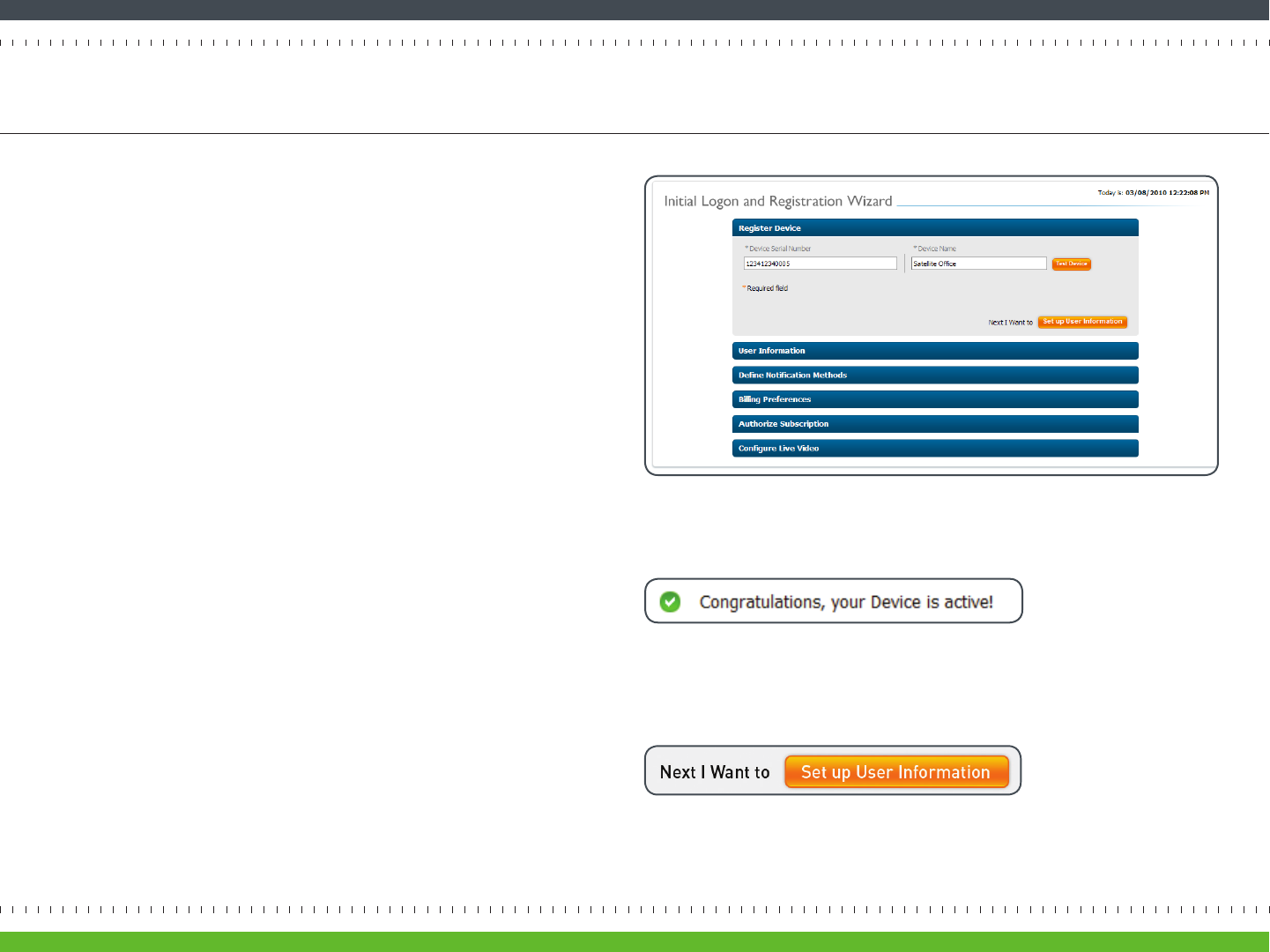
On the Inial Logon and Registraon Wizard page, Register Device secon,
enter a name for your device (Figure 17). The name of the physical locaon
for an Archersh device is recommended (e.g. “Satellite Oce”). Because
Archersh is exible and easy to use, you can change the name at any me.
Click the Test Device buon (Figure 18).
• If the test is successful, you will receive a Congratulaons message (Figure
18). This means that your Archersh Solo has been successfully connected
to the Archersh SmartPortal.
• If the test fails, you’ll be walked through a series of quesons to
troubleshoot the problem. If you need addional help, contact
support@myarchersh.com or call 877.384.3347 (877.3.THEFISH).
Once you have completed a successful Archersh device test, connue with
the Inial Logon and Registraon Wizard page by clicking the Set up User
Informaon buon (Figure 19).
You will be prompted to accept the terms of service. You must agree to the
terms to connue with the installaon.
Step 4 Register Solo (continued)
page 12Archersh Solo Installaon Guide
Figure 17 Customizaon of Device Name
Figure 19 Installaon Wizard buon that will direct you to the next step in the inial
Archersh device registraon process
Figure 18 Congratulaons message, displayed upon successful Archersh device test
The second part of registraon is to register the primary user. The primary
user is usually the owner and main contact of this account, and will dene
system preferences such as adding users to the Archersh system.
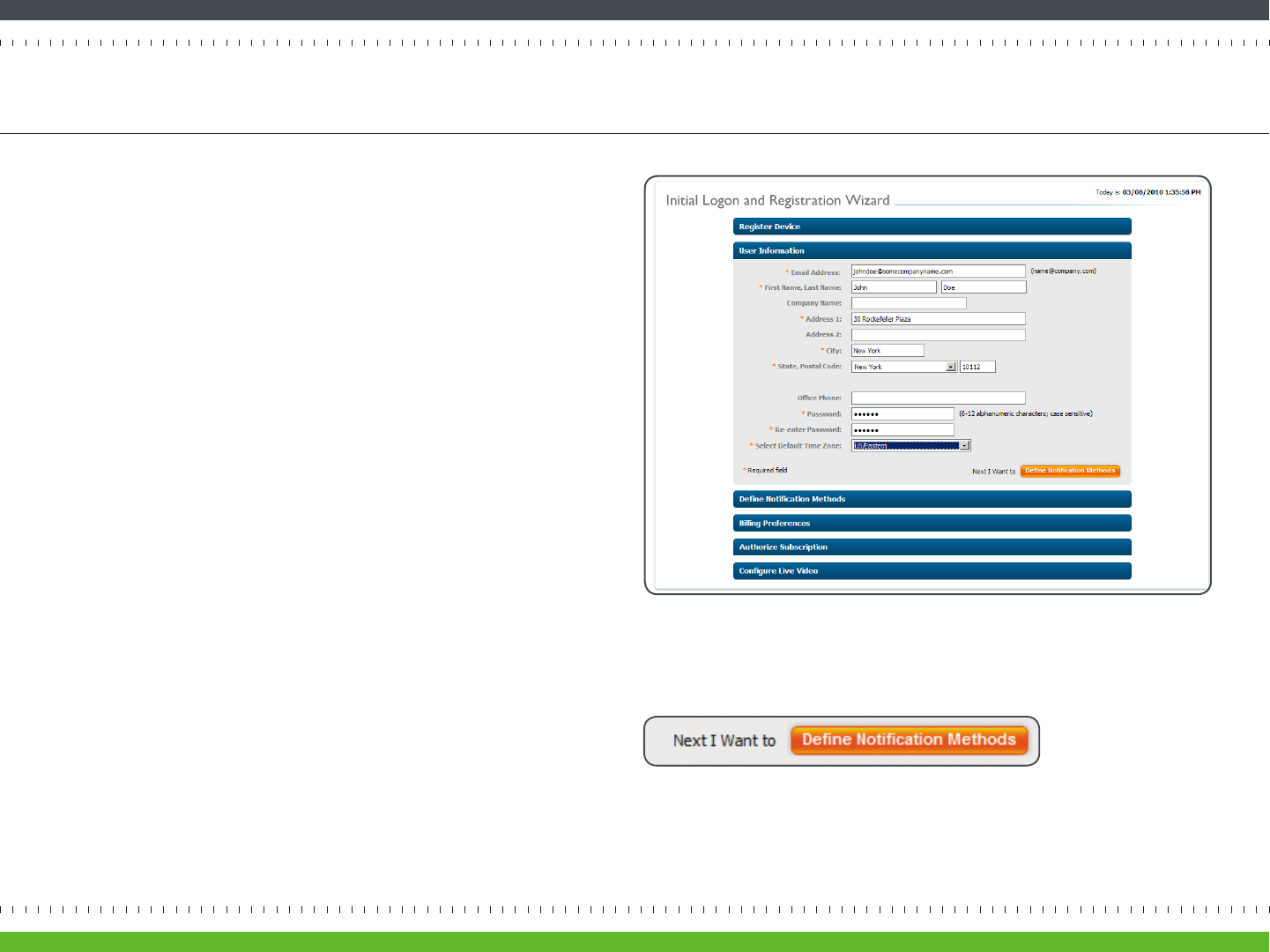
On the Inial Logon and Registraon Wizard page, User Informaon sec-
on, enter the requested informaon in each eld (Figure 20).
Some elds to pay parcular aenon to include:
• Email Address: Enter a valid email address as the primary email ad-
dress that you want associated with your Archersh account. You will
use this same email address to log into your account from
www.myarchersh.com.
• Password: Enter an alphanumeric password between 6 and 12 char-
acters long. Aer inial registraon, you can update your password at
any me via your User Prole page.
• Time Zone: Select the me zone you prefer as the default me zone
for all Archersh devices registered to this account. All event congu-
raon opons and event nocaons will be displayed according to
the me zone you select.
Aer you have completed the required informaon elds, click the Dene
Nocaon Methods buon (Figure 21) to proceed to the next step in the
registraon process.
Step 4-1 Register Primary User
page 13Archersh Solo Installaon Guide
Figure 21 Installaon Wizard buon that will direct you to the next step
Figure 20 Inial Logon and Registraon Wizard page, User Informaon secon
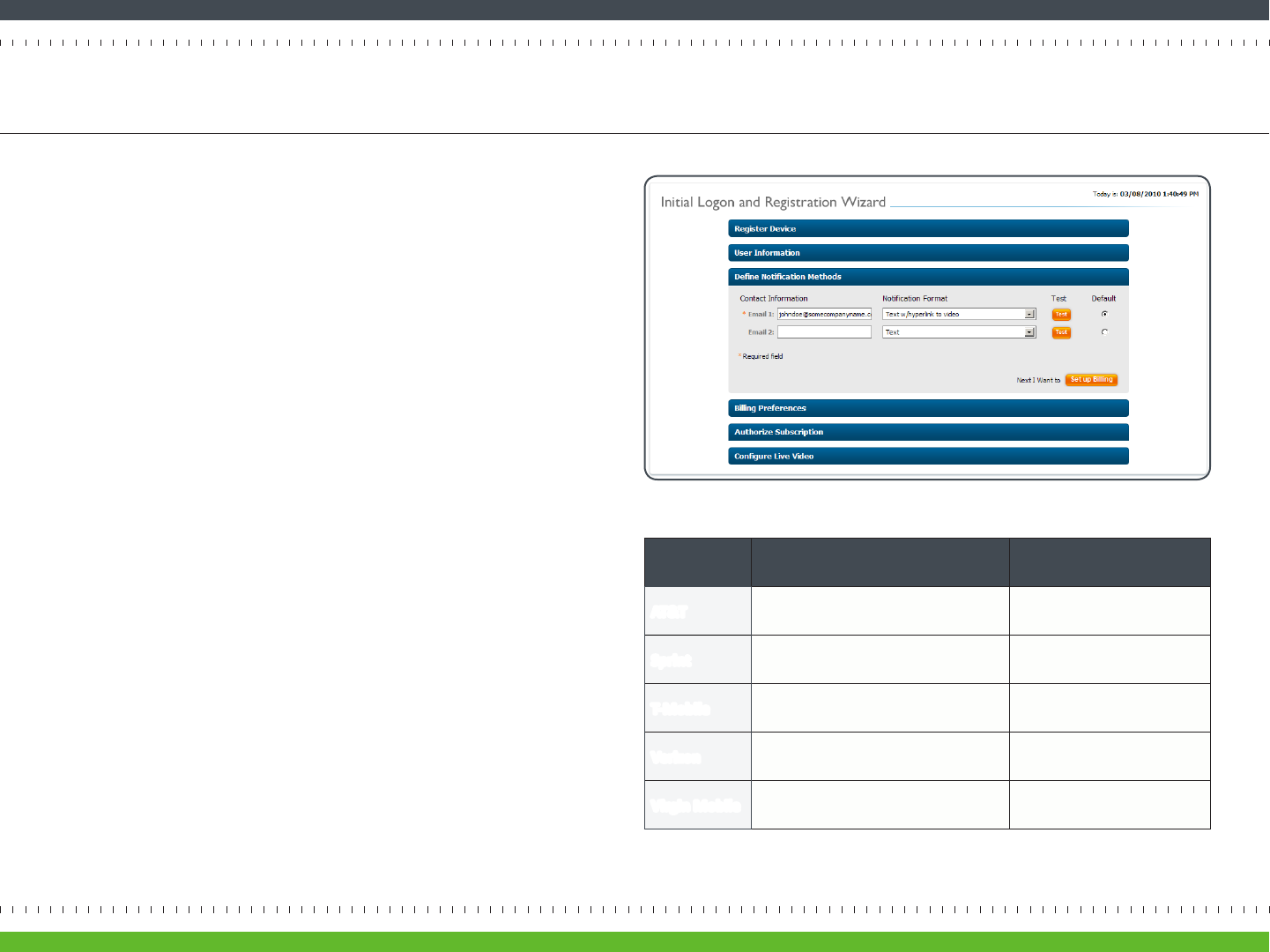
On the Inial Logon and Registraon Wizard page, Dene Nocaon Methods
secon (Figure 22), you can tell Archersh how to send video nocaons and
other messages to you and people that you designate.
• Email 1 and Email 2: The email addresses entered in the last step will
automacally show up in the Email 1 eld. If you also want nocaons sent
to your mobile phone, enter in your phone’s email address in the Email 2 eld
(e.g., a Verizon email address might be 7035551212@vtext.com). Be sure to
use the correct email address for the type of message you want to receive,
SMS for text-only messages and MMS for messages with an aached video or
image, since they may dier. Figure 23 shows SMS and MMS email addresses
for major U.S. wireless providers. Please refer to your provider’s support
documentaon or web site for more informaon.
• Select one of the following Nocaon Formats:
- “Text” means you‘ll receive an SMS all-text nocaon.
- “Text with hyperlink to video” means you’ll receive an SMS nocaon with a
link to the Archersh SmartPortal to view a 10 second clip of the event. This
opon is only for email and not valid for mobile phones.
- “Text with aached sll image” means you’ll receive an MMS nocaon that
includes an aached snapshot of the event.
- “Text with aached video clip” means you’ll receive an MMS nocaon with
a video clip of the event. Choose the le format appropriate for your mobile
phone: MPEG-4 (standard), WMV (Windows phones), 3GPP (other phones),
or MPEG-4 for 3GS (iPhone). If you’re unsure of your format, try each one
starng with MPEG-4 (standard).
Once you have dened an email address and associated it with a Nocaon
Format, click the Test buon to conrm you can receive alerts as expected. If the
test fails, try another Nocaon Format.
Click the Set up Billing buon to proceed to the next step in the registraon
process.
Step 4-2 Define Notification Method for Primary User
Figure 22 Inial Logon and Registraon Wizard page, Dene Nocaons secon
page 14Archersh Solo Installaon Guide
Figure 23 E-mail address format for major U.S. wireless providers
Provider SMS MMS
AT&T mobile number@txt.a.net mobile number@mms.a.net
Sprint mobile number@messaging.sprintpcs.com mobile number@pm.sprint.com
T-Mobile mobile number@tmomail.net mobile number@tmomail.net
Verizon mobile number@vtext.com mobile number@vzwpix.com
Virgin Mobile mobile number@vmobl.com mobile number@vmobl.com
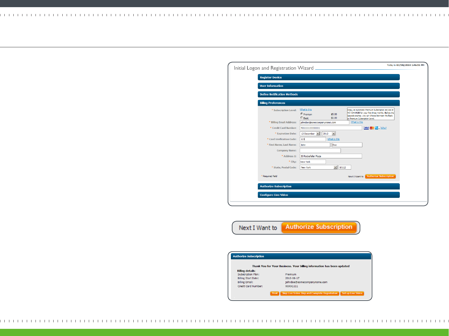
On the Inial Logon and Registraon Wizard page, Billing secon (Figure 24), you can
choose your Archersh SmartPortal Subscripon and method of payment.
Two subscripon levels are available:
• Premium Subscripon provides full Archersh SmartPortal funconality,
including intelligent video ltering and mobile nocaons.
• Basic Subscripon provides remote system operaon and is best for those who
only want to view live and DVR video. The Basic Subscripon is available free of
charge.
Upon the registraon of your rst Archersh device, you will receive an
automac free Premium Subscripon upgrade for three months. Aer the trial
period, you may choose to connue with either subscripon opon. Premium
Subscripons are charged monthly, so you can always update your subscripon
level. More informaon is available at www.myarchersh.com/subscripon.
During inial registraon you are required to enter a valid credit card, even if
you plan to switch to the free Basic Subscripon at the end of the Premium
Subscripon trial.
Fill in your billing informaon and click the Authorize Subscripon buon (Figure
25). You’ll see a screen that summarizes your monthly charges. Click Conrm
Billing.
Click the Set up Live Video buon (Figure 26) and proceed to the next step in the
registraon process.
Step 4-3 Set Billing Preferences
page 15Archersh Solo Installaon Guide
Figure 24 Inial Logon and Registraon Wizard page, Billing Preferences secon
Figure 26 Installaon Wizard provides the opon to skip or set up live video
Figure 25 Installaon Wizard buon that will direct you to the next step
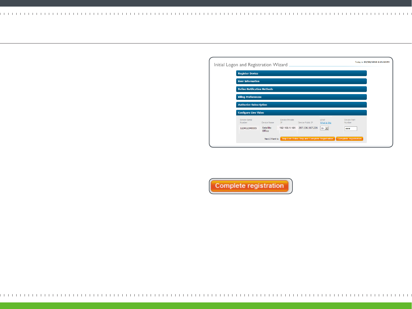
The last step in registraon is to set up live video. Once this step is done,
you’ll be able to see live video from your Archersh Solo in the Archersh
SmartPortal.
On the Inial Logon and Registraon Wizard page, Congure Live Video
secon (Figure 27), you’ll see networking informaon about your Archersh
Solo. For live video to work, port forwarding needs to be set up. Archersh
can automacally set up port forwarding if your router supports Universal
Plug and Play, or UPnP. Just set UPnP to On in the drop down opon.
Once you have turned UPnP on, click the Complete Registraon buon
(Figure 28) to complete the process.
If your router doesn’t support UPnP, select O and refer to “Appendix A:
Port Forwarding Conguraon” on page 23.
Once the registraon process is complete, the Congure Device screen
appears. Proceed to Step 5.
Step 4-4 Set Up Live Video
page 16Archersh Solo Installaon Guide
Figure 27 Inial Logon and Registraon Wizard page, Congure Live Video secon
Figure 28 Installaon Wizard buon that completes the registraon process
Congratulaons, you’ve just completed the Inial Installaon and Registraon
process. Now that Solo has been installed and acvated, this next step will help
you to personalize your Archersh system. You’ll be able to tell Archersh what
you want it to watch for.
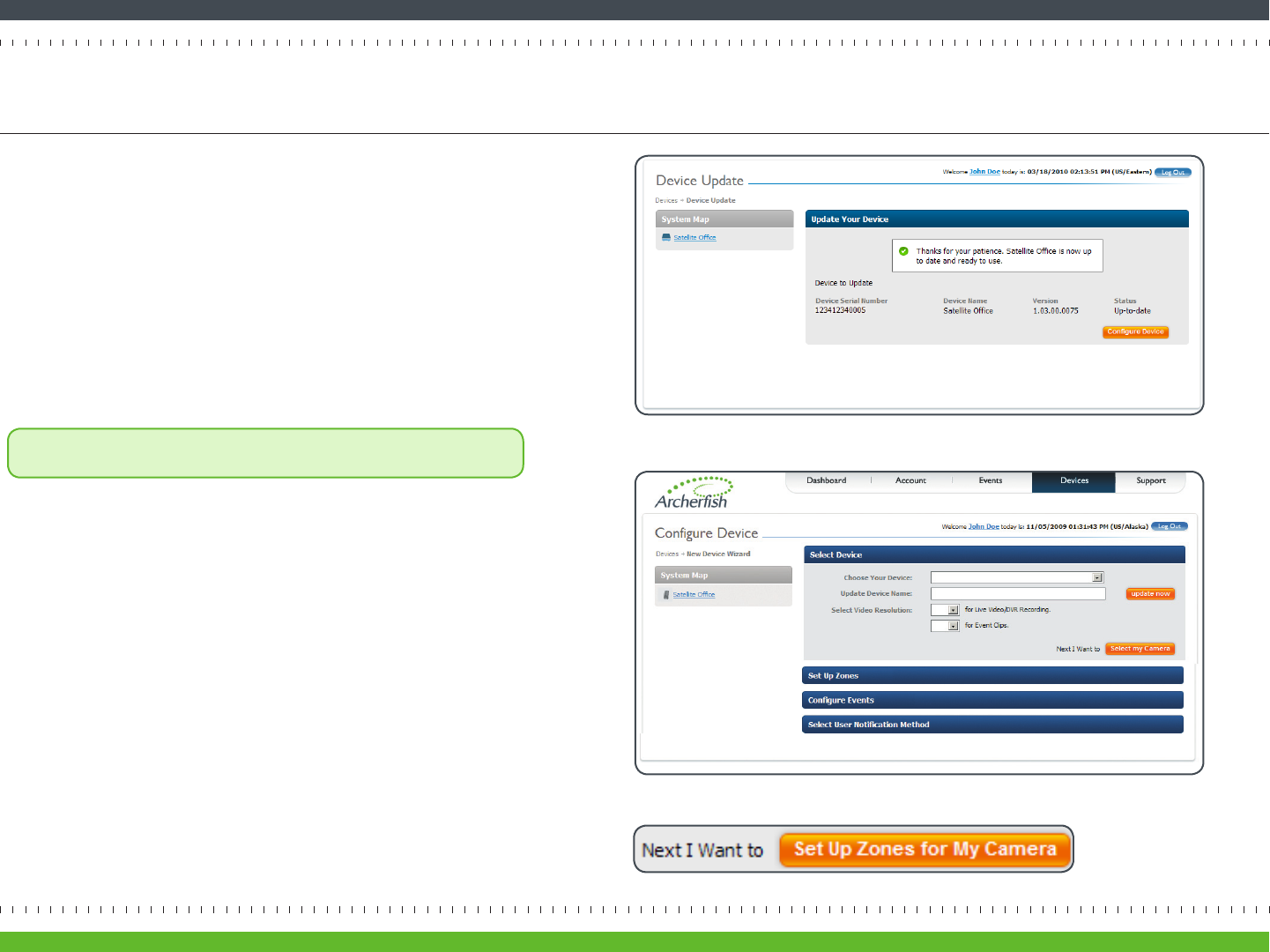
First, Archersh will check to see if there are any updates for your Solo device. This
process should only take a few moments. Once complete, you’ll see a conrmaon
message (Figure 29).
Click the Congure Device buon.
On the Congure Device page, Select Device secon (Figure 30), choose the
Archersh device to customize from the drop down menu.
Note: If you wish to change the name of the Archersh device, enter the
new name in the Update Device eld and click the Update Now link.
For the Select Video Resoluon opon, select Standard for both Live Video/DVR
Recording and Event Clips. This seng will give you good video quality while
opmizing storage.
Click the Set Up Zones for My Camera buon to proceed to the next step (Figure
31).
Step 5 Customize Your System
page 17Archersh Solo Installaon Guide
Figure 30 Congure Device page, Select Device secon
Figure 31 Installaon Wizard buon that will direct you to the next step
Figure 29 Device Update page: Device up-to-date conrmaon
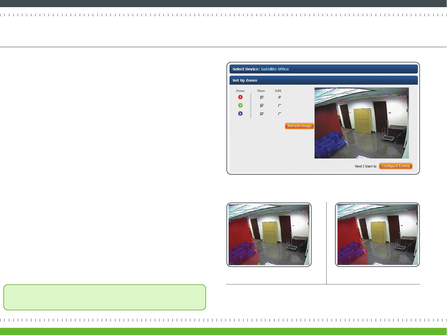
On the Congure Device page, Set Up Zones secon, you can select up to three
specic areas, or zones, within the camera’s view for Archersh to monitor. Zones help
Archersh focus on what maers to you.
For example, Figure 32 shows a camera’s eld of view—an entryway to a small business
oce. The business owner only wants to know when a person tampers with some bins
placed in the entryway. He doesn’t care about acvity in any other part of this camera
view.
It’s easy to create and set the shape of the area you want Archersh to monitor. Don’t
worry about making a mistake. You can always adjust or erase any zone and start over!
• To create a zone, click the Edit radio buon. Then use your mouse to draw the
zone by clicking the le mouse buon wherever you want to dene a corner of the
zone.
• The rst point you create will be colored green; each subsequent point will
be blue.
• When drawing the zone, keep in mind that it should cover the enre area where
Archersh should watch for a person, vehicle, or moving object. It shouldn’t cover
areas where you don’t care about acvity. In the example depicted in Figure 33,
the zone covers the area around the bins placed in the entryway. This area covers
not just the oor in front of the bins, but the area above them to account for the
height of people walking.
• To delete a point of the zone, click it. To move a point, click and drag it to the new
locaon. To create an addional point between two exisng points, SHIFT+click the
point that
was placed rst.
• To complete the zone, click the Congure Events buon, or the Edit radio buon to
set up another zone. A completed zone shows a single red point at the zone’s start
point (Figure 33B).
• To completely erase a zone and start again from scratch, click the red point. If you
want to edit the dimensions of the zone, SHIFT+click the red point.
Note: If you move or reposion a camera, you must click the Refresh Image buon
to see the new camera view and save your sengs.
Step 5-1 Set Up Zones
Figure 32 Congure Device page, Set Up Zones secon
page 18Archersh Solo Installaon Guide
Figure 33 Drawing a zone
A A zone, dened by six end points (rst
point is green; other points are blue)
B A completed zone (start point is
colored red)
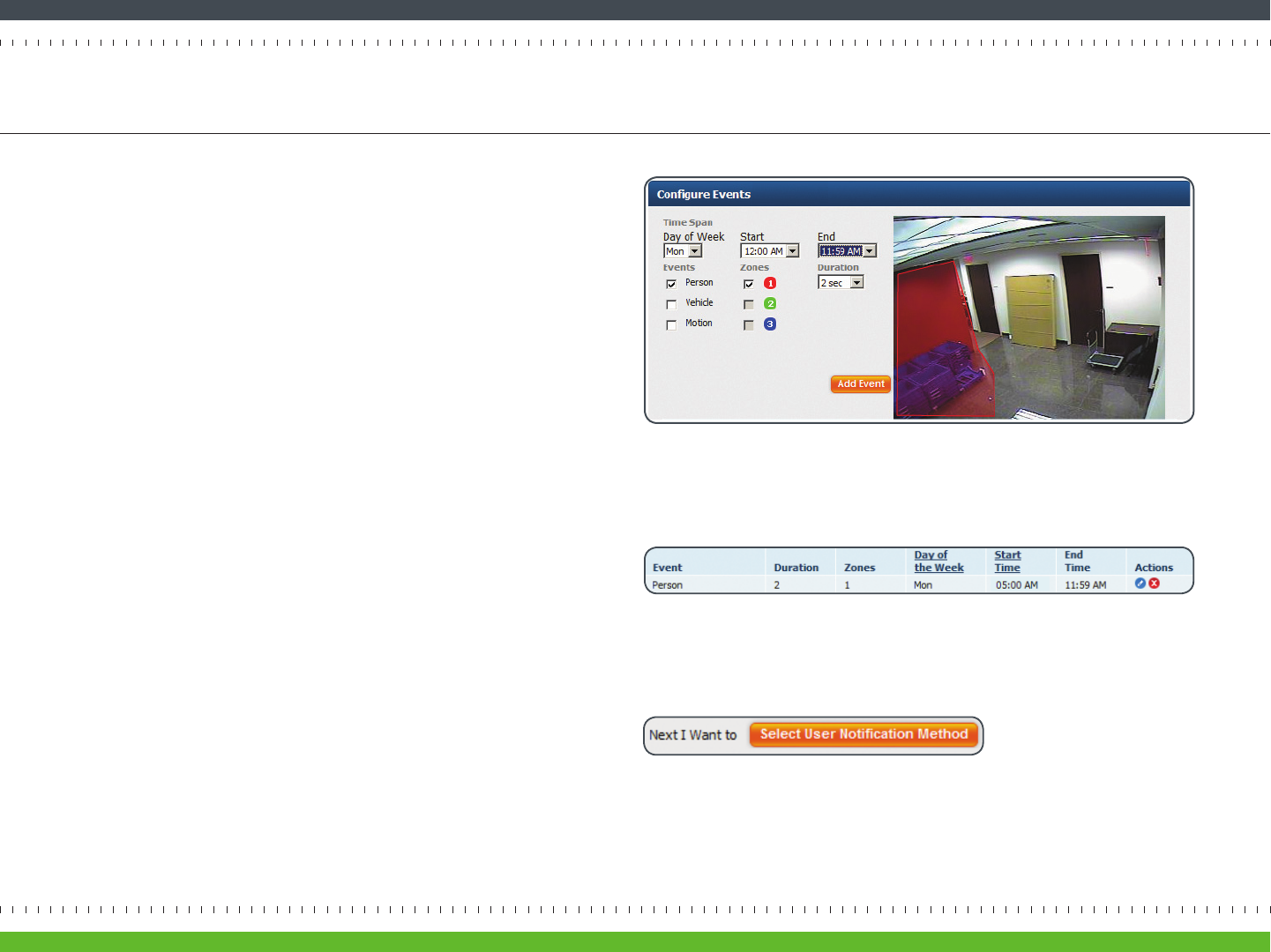
On the Congure Device page, Congure Events secon (Figure 34), you can dene
the events you want Archersh to look for by using the following opons:
• Time Span: Use the drop down menus to select the Day of Week [day], Start
[me] and End [me] that you want Archersh to look for an event.
• Events: Select the type(s) of event you want Archersh to look for. You can
tell Archersh to look for a person, vehicle, or moon. You can also select a
combinaon of these. For instance, if Archersh is monitoring your driveway,
you might choose to have Archersh nofy you when a car or person comes up
the driveway. Note that if you choose Moon, you’ll be noed of any object
moving in the camera view.
• Zones: Select the zones where Archersh should look for the event. You will
only be able to select zones that you have already dened.
• Duraon: Select the amount of me the event (e.g., person, vehicle, or object)
stays within the zone before Archersh noes you. Seng a duraon is
helpful in focusing Archersh on the things that maer (a person loitering)
versus things that don’t (a person passing through).
Using the same example from Step 5-1, if you wanted to detect people who might
be tampering with some bins on Monday morning, you might set the Time Span to
Monday between 5:00 AM and 11:59 AM and the Events as Person.
Once you have dened your event, click the Add Event buon. You will see your
event in the table (Figure 35) and can edit or delete the event at any me.
Click the Select User Nocaon Method buon to proceed (Figure 36).
Step 5-2 Configure Events
page 19Archersh Solo Installaon Guide
Figure 35 Event table
Figure 34 Congure Device page, Congure Events secon
Figure 36 Installaon Wizard buon that will direct you to the next step
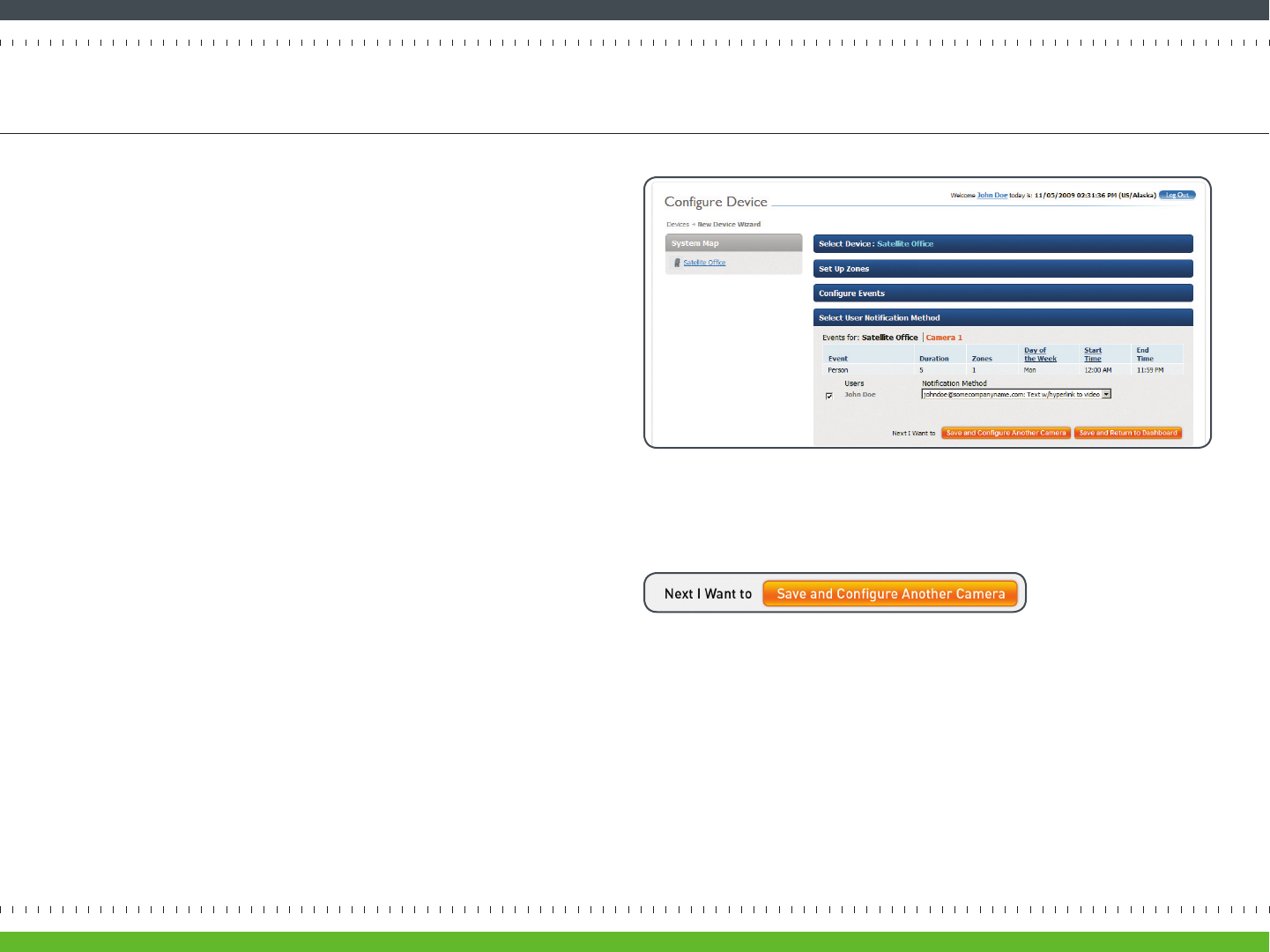
On the Congure Device page, Select User Nocaon Method secon (Figure 37),
you can decide how nocaons will be received, and who will receive them. Since
Archersh is exible, dierent nocaon sengs can be dened for dierent
cameras.
The Primary User name and nocaon methods that were completed in the
Primary User Prole will automacally appear in the Users list.
Select the user(s) who should receive nocaons for this camera. Then use the
drop down box under Nocaon Method to choose the desnaon and format of
their nocaons.
Click the Save and Return to Dashboard or the Save and Congure Another Camera
buon (Figure 38).
Congratulaons! Archersh is now ready to watch for you.
Step 5-3 Define Notification Methods by Camera
page 20Archersh Solo Installaon Guide
Figure 37 Congure Device page, Dene Nocaons secon
Figure 38 Installaon Wizard buon that will direct you to the next step
Once you have registered your Archersh device, you can access the Archersh
SmartPortal at www.myarchersh.com. Aer you sign in, you will automacally be
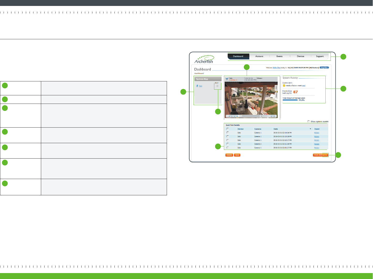
directed to the Dashboard page (Figure 39).
Within the Dashboard, you have access to several key features:
For addional informaon on these Dashboard features and other aspects of the
Archersh SmartPortal, please refer to the Archersh Online Help.
Now that You’re Done Using the Dashboard
page 21Archersh Solo Installaon Guide
System Map Displays the names of every Archersh device
and associated camera in your Archersh system
PLAY Buon Lets you view live video from any camera in your Archersh system
Video Viewer Displays live video, event video clips, or DVR video. Moving your mouse over
the Video Viewer displays DVR opons for accessing a specic me frame in
the video
Last Ten
Events Table
Lists the 10 most recent events, including system events related to the health
of the overall system (e.g., loss of video, loss of Internet)
View All
Events Buon
Directs you to another page that displays all events currently stored within
your Archersh SmartPortal
System
Acvity
Summary
Provides informaon about the amount of storage used, the number
of events since your last log in, and whether any system alerts are present
Navigaon
Bar
Allows you to make changes to your system
Figure 39 Dashboard page
1
1
2
3
4
5
6
7
2
4
5
7
6
3

Here are some helpful hints that will help you make the most of your Archersh system.
• Locaon, Locaon, Locaon: Just like with real estate, locaon is one of the key
factors in using Solo eecvely. While you don’t have to follow all of the camera
placement guidelines listed on page 9, following as many as possible makes Solo a
more powerful tool. Our Camera Placement Guide (available at www.myarchersh.
com/solosetup) gives more details on placement and provides real-world examples of
typical sengs.
• Start slowly: Archersh allows for a high level of customizaon, so it’s best to slowly
experiment and gure out what works best for you. Try sending nocaons to yourself
in dierent formats to see what you like, and then add other users. Set up one camera
at a me and experiment with event duraon, zone placement, and dierent behaviors
to see which events are most useful.
• Use zones: Especially in busy scenes, using zones within a camera eld of view can help
increase the accuracy of your nocaons since Archersh will focus on looking for
events only in the area(s) you care about.
• Use duraon: Leng Archersh wait a bit before reporng something to you can be
helpful, especially if you are concerned about people loitering in an area versus those
that just pass by.
• For outdoor scenes, use People or Vehicle Behaviors: Archersh can detect more
than just whether or not things are moving. Archersh can actually tell the dierence
between people and vehicles. We recommend seng Archersh to look for these
behaviors over general moon for outdoor monitoring since wind, shadows and other
kinds of movement may trigger unwanted nocaons.
• Pets can look like people: Occasionally Archersh may consider your very large family
pet to be a person. If you have a pet that frequently gets in the camera eld of view,
consider poinng the camera in a dierent direcon or using zones to ignore their
favorite places.
Helpful Hints in Making Archerfish Work for You
page 22Archersh Solo Installaon Guide
This secon describes how to manually set up port forwarding in order to view live
video in the Archersh SmartPortal. This secon only applies if you set UPnP to O
on the Inial Logon and Registraon Wizard, Congure Live Video secon (see page
16).
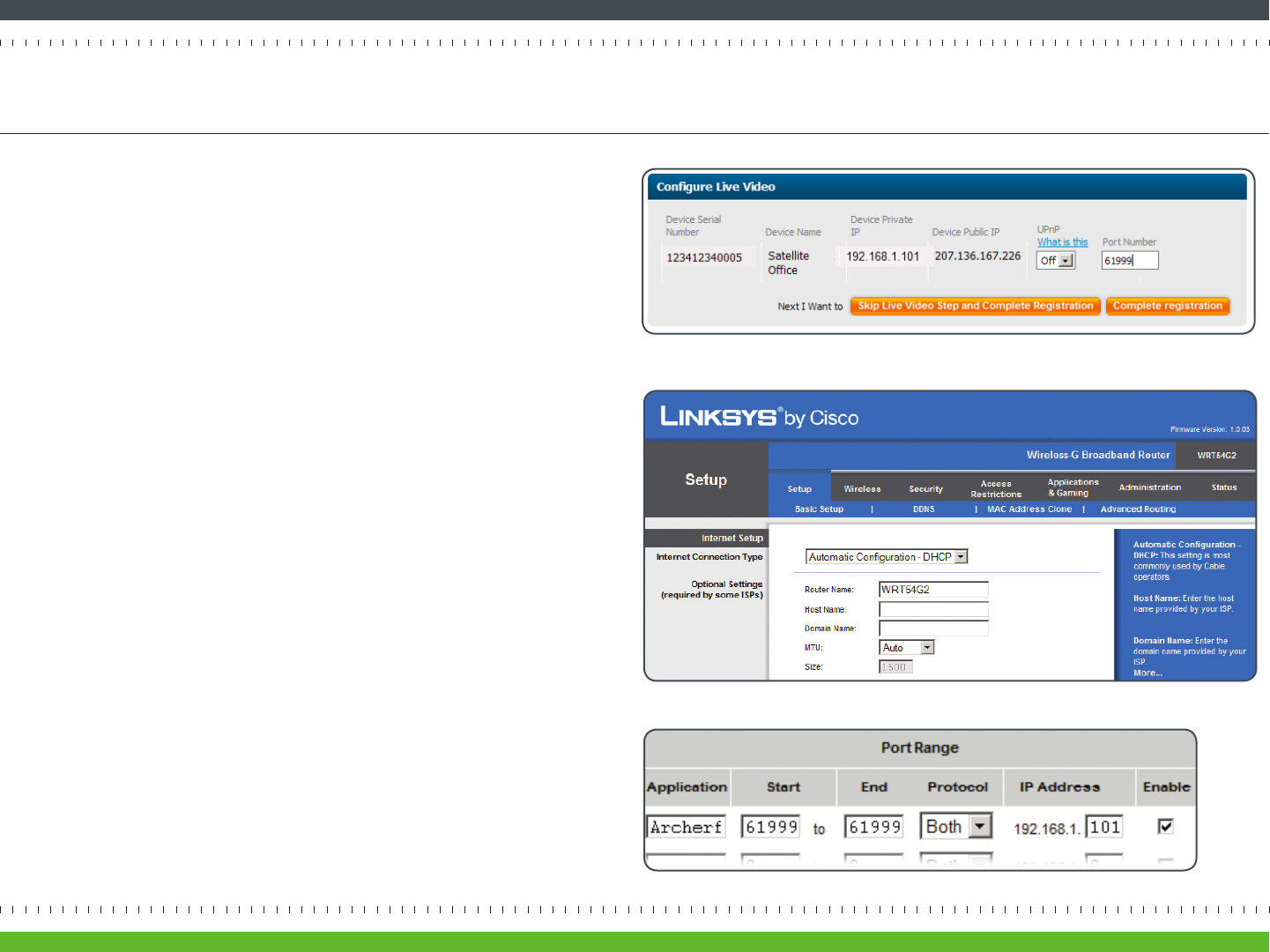
Next, in the Device Port Number eld enter a port number between 1024 and
65535 (Figure 40). This helps avoid potenal conicts with port numbers already
in use. If you have more than one Archersh device, make sure each device has its
own unique port number.
Next, set up port forwarding by using your router to map the Archersh device
private IP address to the port number you’ve chosen. You’ll need administrave
rights to log on to your router. Specic instrucons vary by manufacturer, so you
should refer to your router manufacturer’s web site for details. If your router is
provided by your Internet Service Provider, their technical support can provide
instrucons for your router.
Here’s an example of how to set up port forwarding for a Cisco® Linksys® WRT54G2
router:
• On the page displayed when you rst log into the router (Figure 41), select the
Applicaons & Gaming tab.
• On the Applicaons & Gaming page, enter “Archersh” in the Applicaon
eld. In the Start and End elds, enter the Device Port Number that appears
in the Archersh SmartPortal’s Live Video Setup (in this case, 61999). On the
same line, enter the last numbers of the Device Private IP Address. Make sure
that the Enable box is checked. In the example in Figure 42, the Device Port
Number is 61999 and the Device IP Address is 192.168.1.101.
• Click the Save Sengs buon.
page 23Archersh Solo Installaon Guide
Appendix A: Port Forwarding Set Up
Figure 41 Linksys WRT54G2 main conguraon page
Figure 42 Required elds to set up port forwarding
Figure 40 Specifying a port number for Live Video

DEVICE
ON
AWAITING BOOT
-or- ERROR BOOTING ETHERNET WI-FI RECORDING RESET
BUTTON
LIGHT OFF
SOLID RED • •
BLINKING ORANGE • •
SOLID ORANGE •
SOLID GREEN • •
BLINKING GREEN • • •
SOLID GREEN
(ORANGE FLASHES) • •
BLINKING GREEN
(ORANGE FLASHES) • • •
BLINKING GREEN/
BLINKING RED • •
page 24Archersh Solo Installaon Guide
Appendix B: Solo Device LED Quick Reference
Archersh Solo has a small LED light on the boom which helps it to visually communicate what’s going on.
Generally speaking, a green light means it’s transming video, an orange light has to do with Wi-Fi connecvity, and a red
light means Solo is having trouble or being reset. If there is a specic color and light paern you want more informaon on,
check out the table below.
All content included in this publicaon, such as text, graphics, logos, buon icons, images, referenced digital downloads, data compilaons, and soware, is the intellectual property of Cernium Corporaon or its content
suppliers and protected by United States and internaonal copyright laws. No part of the Archersh Online Help, Archersh Solo Installaon Guide, or Camera Placement Guide may be reproduced, transmied, transcribed,
stored in a retrieval system, or translated into any language in any form, by any means, without Cernium’s prior wrien permission.
Cernium reserves the right to change the specicaons of Archersh Solo Interacve Video Monitoring and Recording System and Archersh SmartPortal described in these guides at any me and without prior noce.
EXCEPT AS EXPRESSLY REPRESENTED OR WARRANTED IN AN END USER LICENSE AGREEMENT, ARCHERFISH, THIS INSTALLATION GUIDE AND RELATED DOCUMENTATION ARE PROVIDED “AS IS.” TO THE MAXIMUM EXTENT
PERMITTED BY APPLICABLE LAW, CERNIUM DISCLAIMS ANY AND ALL OTHER PROMISES, REPRESENTATIONS AND WARRANTIES, WHETHER EXPRESS, IMPLIED OR STATUTORY, INCLUDING, BUT NOT LIMITED TO, ANY
WARRANTIES OF FITNESS FOR A PARTICULAR PURPOSE, MERCHANTABILITY, NON-INFRINGEMENT OR SYSTEM INTEGRATION. NO WARRANTY IS MADE BY CERNIUM ON THE BASIS OF TRADE USAGE, COURSE OF DEALING OR
COURSE OF TRADE. CERNIUM DOES NOT WARRANT THAT ARCHERFISH, THIS INSTALLATION GUIDE OR THE RELATED DOCUMENTATION WILL MEET END USERS’ REQUIREMENTS. THIS INSTALLATION GUIDE IS PROVIDED FREE
OF CHARGE AND IN NO EVENT WILL CERNIUM BE LIABLE FOR ANY DAMAGES WHATSOEVER ARISING FROM OR IN CONNECTION WITH THIS INSTALLATION GUIDE.
While every eort has been made to ensure that the informaon in these guides are accurate and complete, we would appreciate if any errors or omissions were brought to our aenon by emailing us at support@
myarchersh.com.
Archersh Solo Installaon Guide (7AFSLGD000E-01.15) May 2010.
Cernium, Archersh, Archersh Solo and Archersh SmartPortal are registered marks of Cernium Corporaon.
Windows and Windows Media Video (WMV) are registered marks of Microso Corporaon. iPhone is a registered mark of Apple Inc. Adobe and Flash are registered marks of Adobe Systems Incorporated. Linksys is a
registered mark of Cisco Systems, Inc.
Changes or modicaons not expressly approved by Cernium Corporaon could void the user’s authority to operate the equipment.
NOTE: This equipment has been tested and found to comply with the limits for a Class B digital device, pursuant to part 15 of the FCC Rules. These limits are designed to provide reasonable protecon against harmful
interference in a residenal installaon. This equipment generates, uses and can radiate radio frequency energy and, if not installed and used in accordance with the instrucons, may cause harmful interference to radio
communicaons. However, there is no guarantee that interference will not occur in a parcular installaon. If this equipment does cause harmful interference to radio or television recepon, which can be determined by
turning the equipment o and on, the user is encouraged to try to correct the interference by one or more of the following measures:
• Reorient or relocate the receiving antenna.
• Increase the separaon between the equipment and receiver.
• Connect the equipment into an outlet on a circuit dierent from that to which the receiver is connected.
• Consult the dealer or an experienced radio/ TV technician for help.
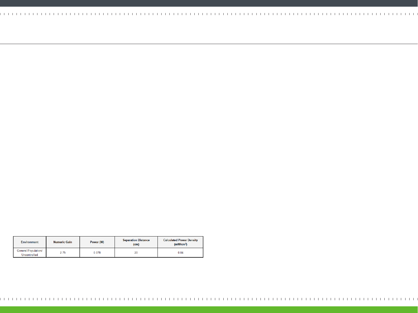
Radiaon Exposure Statement
This equipment shall only be installed and operated with antenna gain not more than that shown in the table below, and installed with a minimum of 20 cm of separaon distance between the antenna and the general
public.
This device complies with Part 15 of the FCC Rules. Operaon is subject to the following two condions:
(1) this device may not cause harmful interference, and (2) this device must accept any interference received, including interference that may cause undesired operaon.
Copyright © 2010 Cernium Corporaon. All rights reserved.
page 25Archersh Solo Installaon Guide