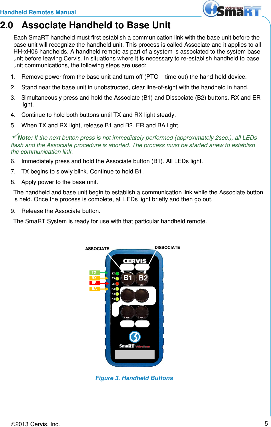
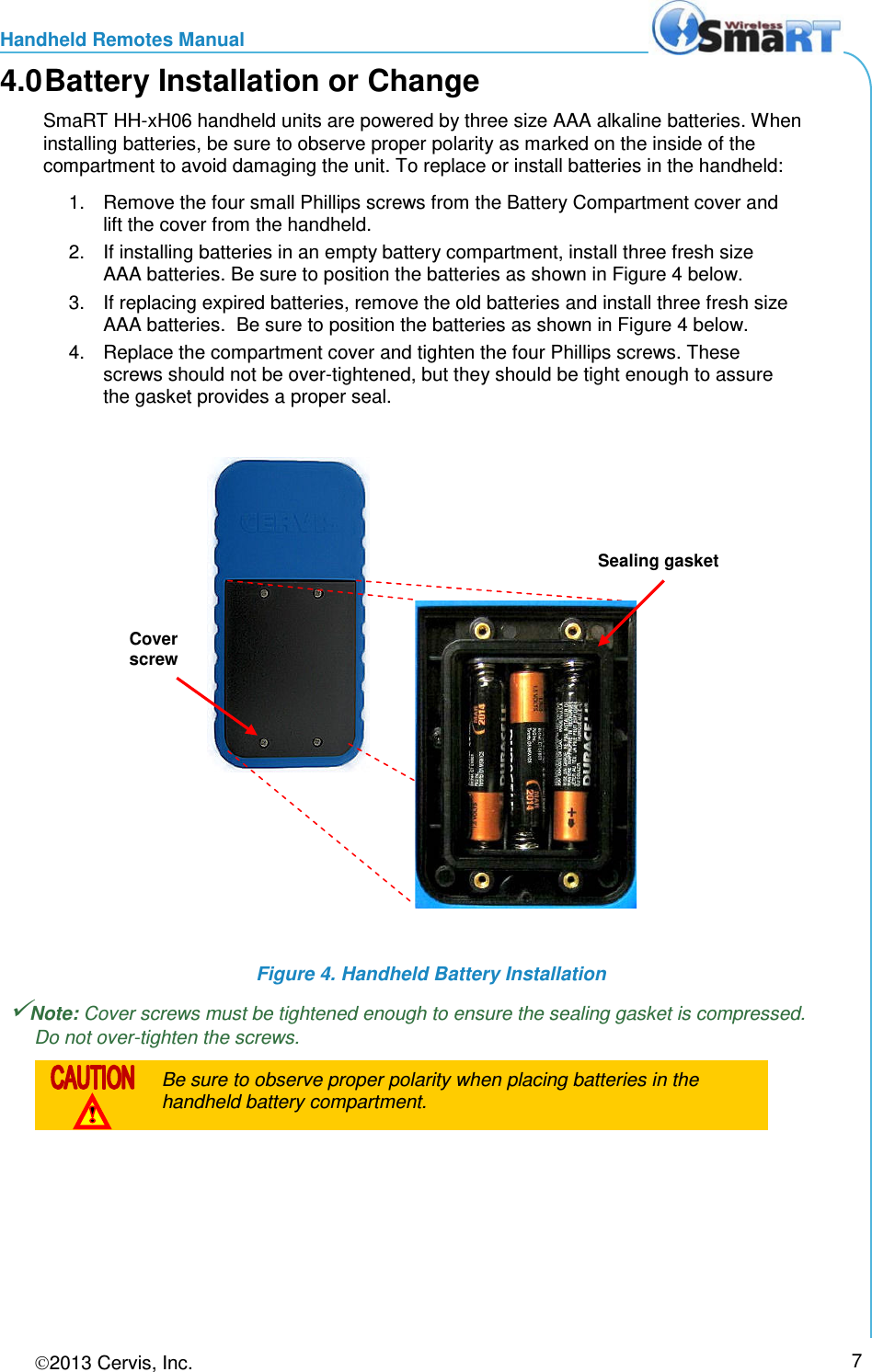
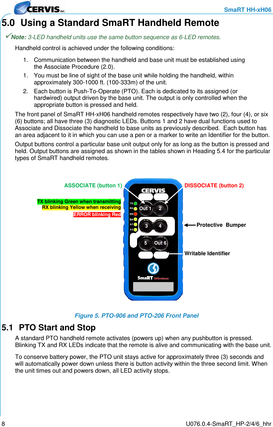
Cervis 2H06 SmaRT Portable Radio User Manual SmaRT HH xH06 Handheld Remotes Manual
Cervis Inc. SmaRT Portable Radio SmaRT HH xH06 Handheld Remotes Manual
UserManual.wiki
>
Cervis
>
2H06 User Manual
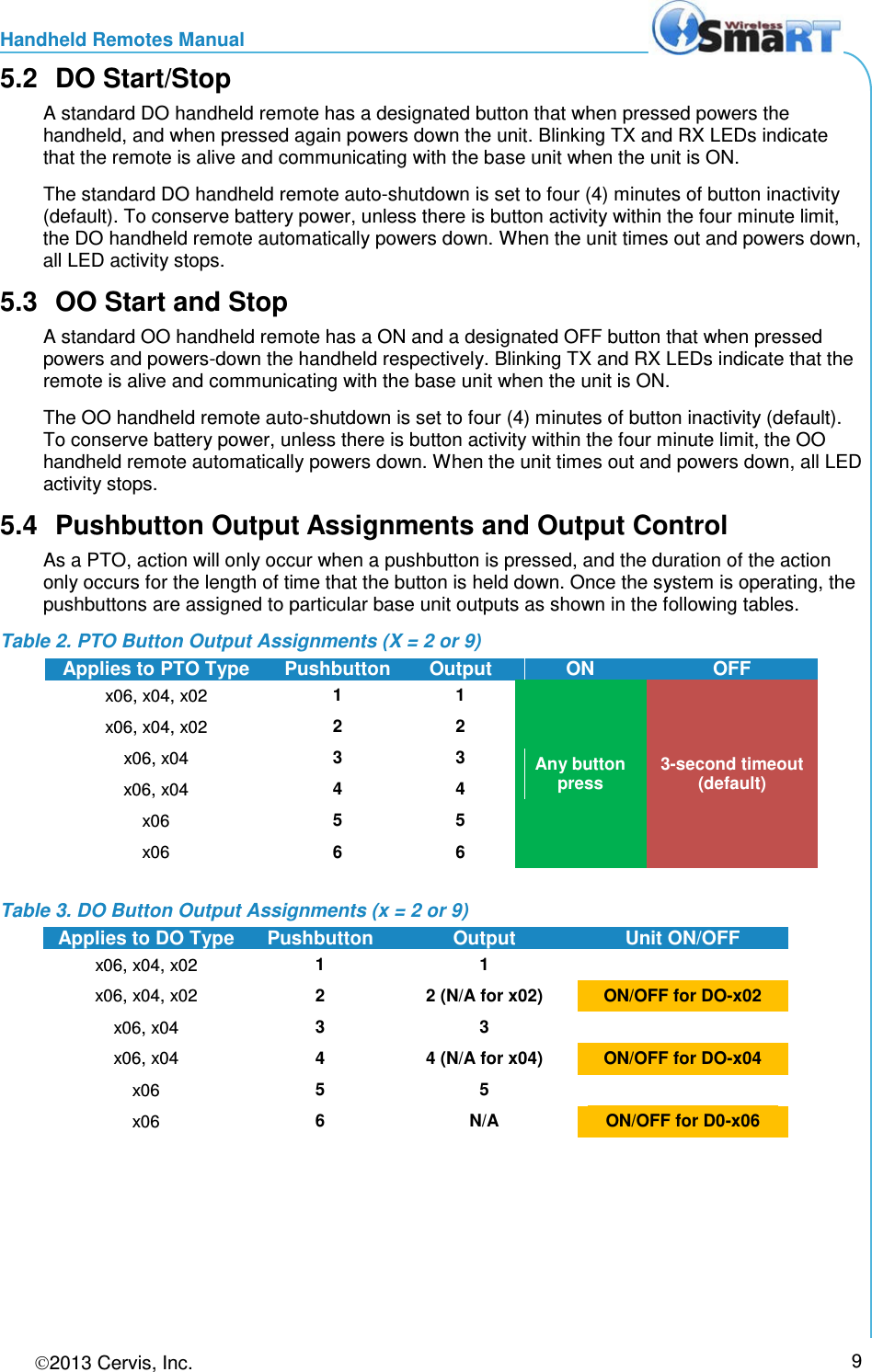
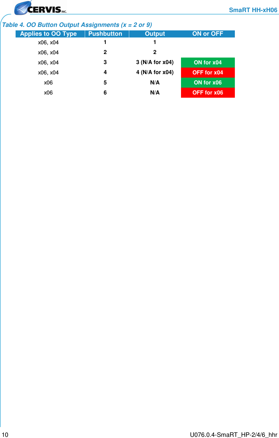
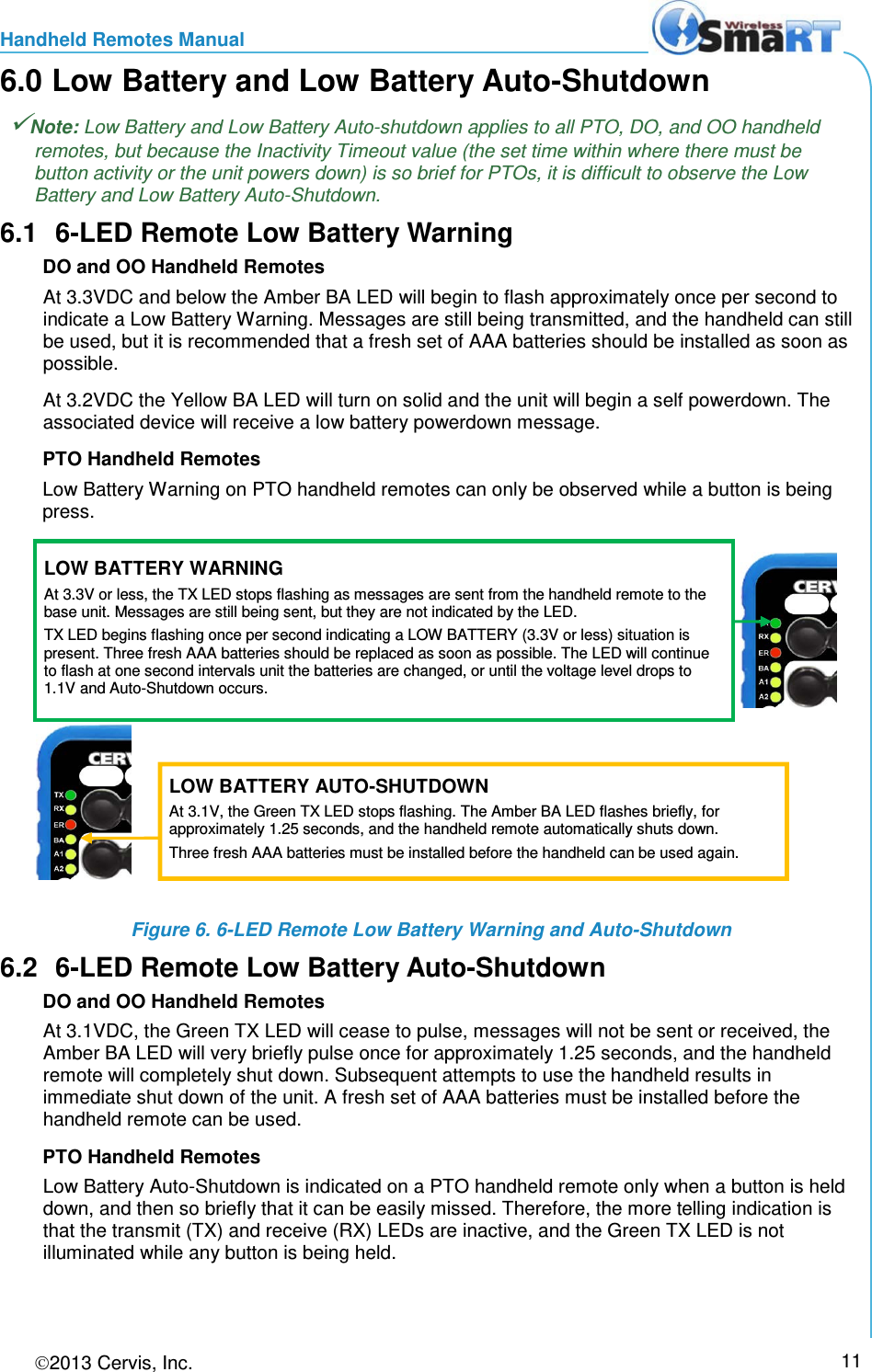
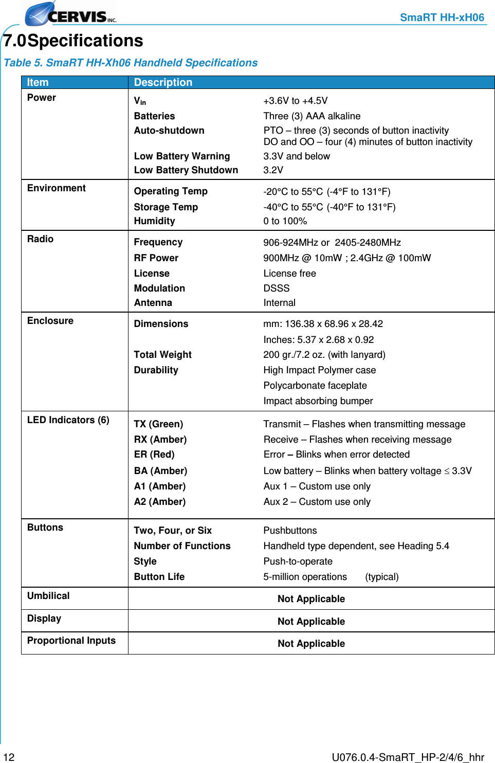
Users Manual
Navigation menu
Upload a User Manual
Namespaces
Wiki Guide
HTML
PDF
Info
Views
User Manual
Discussion / Help
Navigation