Cervis 2H06 SmaRT Portable Radio User Manual SmaRT HH xH06 Handheld Remotes Manual
Cervis Inc. SmaRT Portable Radio SmaRT HH xH06 Handheld Remotes Manual
Cervis >
Users Manual

2013 Cervis, Inc.
HH-xH06 Manual
DN: U076.0.4-SmaRT_HP-2/4/6_hhr
™
™
SmaRT HH-xH06
This document is the property of Cervis, Inc. and cannot be copied, modified, e-mailed, or reproduced
without the express prior written consent of Cervis, Inc.
Cervis, Inc. reserves the right to change this manual or edit, delete, or modify any information without prior
notification.
FCC Statements
15.19 – Two Part Warning
This device complies with Part 15 of the FCC rules. Operation is subject to the following two conditions:
(1) This device may not cause harmful interference and
(2) This device must accept any interference received, including interference that may cause undesired operation.
15.21 – Unauthorized Modification
NOTICE: The manufacturer is not responsible for any unauthorized modifications to this equipment made by the user. Such modifications could
void the user’s authority to operate the equipment.
15.105(b) – Note:
Note: This equipment has been tested and found to comply with the limits for a Class B digital device, pursuant to part 15 of the FCC Rules. These limits are
designed to provide reasonable protection against harmful interference in a residential installation. The equipment generates, uses and can radiate radio
frequency energy and, if not installed and used in accordance with the instructions, may cause harmful interference to radio communications. However,
there is no guarantee that interference will not occur in a particular installation. If this equipment does cause harmful interference to radio or television
reception, which can be determined by turning the equipment off and on, the user is encouraged to try to correct the interference by one or more of the
following measures:
—Reorient or relocate the receiving antenna.
—Increase the separation between the equipment and receiver.
—Connect the equipment into an outlet on a circuit different from that to which the receiver is connected.
—Consult the dealer or an experienced radio/TV technician for help.
Industry Canada Statement
This device complies with Industry Canada licence-exempt RSS standard(s). Operation is subject to the following two conditions: (1) this device may not cause
interference, and (2) this device must accept any interference, including interference that may cause undesired operation of the device.
Le présent appareil est conforme aux CNR d'Industrie Canada applicables aux appareils radio exempts de licence. L'exploitation est autorisée aux deux
conditions suivantes : (1) l'appareil ne doit pas produire de brouillage, et (2) l'utilisateur de l'appareil doit accepter tout brouillage radioélectrique subi, même si
le brouillage est susceptible d'en compromettre le fonctionnement.
RoHS Compliance Statement
Cervis, Inc. complies with the requirements of Restriction of Hazardous Substances (RoHS/WEEE) Specification based on in-house practice and
declaration of compliance from our vendors. For additional information concerning RoHS compliance, please contact Cervis, Inc. at:
CERVIS, Inc.
170 Thorn Hill Road Warrendale, PA 15086
Phone: 724.741.9000 Fax: 724.741.9001
This product may contain material that may be hazardous to human health and the environment. In compliance with EU
Directive 2002/96/EC on Waste Electrical and Electronic Equipment (WEEE):
Do not dispose of the product as unsorted municipal waste.
This product should be recycled in accordance with local regulations. Contact local authorities for detailed
information.
This product may be returnable to the distributor for recycling. Contact your distributor for details.
Industry Canada Statement
This device complies with Canadian RSS-210.
The installer of this radio equipment must ensure that the antenna is located or pointed such that it does not emit RF field in excess of Health Canada limits for
the general population; consult Safety Code 6, obtainable from Health Canada’s website www.hc-sc.gc.ca/ewh-semt/pubs/radiation/radio_guide-lignes_direct-
eng.php.
Cet appareil est conforme à la norme canadienne RSS-210.
L'installateur de cet équipement radio doit s'assurer que l'antenne est située ou dirigée de manière à ne pas émettre un champ RF excédant les limites
imposées par Santé Canada pour la population en général; consultez le Code de sécurité 6, disponible sur le site web de Santé Canada www. hc-
sc.gc.ca/ewh-semt/pubs/radiation/radio_guide-lignes_direct-eng.php.
Handheld Remotes Manual
2013 Cervis, Inc.
i
Notes/Definitions
Associate
SmaRT configuration method using a series of specific remote unit button presses to establish a
communication link between a SmaRT Handheld and a SmaRT Base Unit.
DSSS
Direct sequence spread spectrum; an advanced wireless communication technology.
Dissociate
Dissolution of all established communication links between handhelds and a base unit.
PTO
Push to Operate: Command broadcast only while a button is depressed. The command ends
when the button is released.
DO
Dual Operation: Used to define handheld remotes that use one button for two operations. For
instance, the SmaRT DO-206 handheld remote uses one button (button 6, typical) to both turn
on the handheld remote and turn the units off.
OO
On and Off Operation: Where two buttons or buttons are used for two operations or processes.
For instance, the SmaRT DO-206 handheld remote uses one button (button 6, typical) to both
turn on the handheld remote and turn the unist off.
Line of Sight (aka Direct-Line-of-Sight)
Type of communication between transceivers, or a transmitter and a receiver, where the
pathway between the two units must be clear of obstacles.
TX/RX
Transmit/Receive
Document Conventions
Note: Notes are used to indicate points of interest or pertinent information.
Cautions are used to warn of serious consequences of actions or inactions that may
result in injury, death, or serious damage to the equipment.

SmaRT HH-xH06
U076.0.4-SmaRT_HP-2/4/6_hhr
ii
Table of Contents
Document Conventions ................................................................................................................ i
List of Figures ............................................................................................................................... ii
List of Tables ................................................................................................................................. ii
Cervis Inc. Safety Precautions .................................................................................................... 1
1.0 SmaRT Two, Four and Six Button Handheld Remotes ..................................................... 2
1.1 DO and OO Button Operation .......................................................................................... 4
2.0 Associate Handheld to Base Unit ....................................................................................... 5
3.0 Dissociate Handheld from Base Unit ................................................................................. 6
4.0 Battery Installation or Change ............................................................................................ 7
5.0 Using a Standard SmaRT Handheld Remote ..................................................................... 8
5.1 PTO Start and Stop ........................................................................................................... 8
5.2 DO Start/Stop ..................................................................................................................... 9
5.3 OO Start and Stop ............................................................................................................. 9
5.4 Pushbutton Output Assignments and Output Control .................................................. 9
6.0 Low Battery and Low Battery Auto-Shutdown ................................................................ 11
6.1 6-LED Remote Low Battery Warning ............................................................................. 11
6.2 6-LED Remote Low Battery Auto-Shutdown ................................................................ 11
7.0 Specifications ..................................................................................................................... 12
8.0 Spare Parts List .................................................................................................................. 13
Appendix A: HH-x06 Product Variation List............................................................................. 14
Appendix B: Exposure to Radio Frequency Energy ............................................................... 15
Appendix C: Agency Identification Label Locations .............................................................. 15
List of Figures
Figure 1. HH-xH06 6-LED Handheld Remote Button Assignments ...........................................3
Figure 2. Standard PTO Six button Example ...............................................................................4
Figure 3. Handheld Buttons ...........................................................................................................5
Figure 4. Handheld Battery Installation ........................................................................................7
Figure 5. PTO-906 and PTO-206 Front Panel ...............................................................................8
Figure 6. 6-LED Remote Low Battery Warning and Auto-Shutdown...................................... 11
Figure 7. Agency Identification Label Locations ...................................................................... 15
List of Tables
Table 1. HH-xH06 Naming Conventions .......................................................................................2
Table 2. PTO Button Output Assignments (X = 2 or 9) ...............................................................9
Table 3. DO Button Output Assignments (x = 2 or 9)..................................................................9
Table 4. OO Button Output Assignments (x = 2 or 9) .............................................................. 10
Table 5. SmaRT HH-Xh06 Handheld Specifications ................................................................. 12
Table 6. Spare Parts List ............................................................................................................. 13
Table 7. HH-x06 Product Variation List ..................................................................................... 14

Handheld Remotes Manual
Cervis Inc. Safety Precautions
Read and follow all instructions.
Failure to abide by Safety Precautions may result in equipment failure, loss of
authority to operate the equipment, and personal injury.
Use and maintain proper wiring. Follow equipment manufacturer instructions.
Improper, loose, and frayed wiring can cause system failure, equipment damage, and
intermittent operation.
Changes or modifications made to equipment not expressly approved by the
manufacturer will void the warranty.
Owner/operators of the equipment must abide by all applicable Federal, State, and
Local laws concerning installation and operation of the equipment. Failure to comply
could result in penalties and could void user authority to operate the equipment.
Make sure that the machinery and surrounding area is clear before operating. Do not
activate the remote control system until certain that it is safe to do so.
Turn off the handheld remote and remove power from the base unit before attempting
any maintenance. This will prevent accidental operation of the controlled machinery.
Power can be removed from the handheld remote by removing the source power
(batteries) from the circuit.
Power can be removed from the Base Unit by removing the source power from the
circuit.
Use a damp cloth to keep units clean. Remove mud, concrete, dirt, etc. after use to
prevent obstructing or clogging the buttons, levers, wiring, and switches.
Do not allow liquid to enter the handheld or base unit enclosures. Do not use high
pressure equipment to clean the handheld remote or base unit.
Disconnect the radio base unit before welding on the machine. Failure to disconnect
the base unit may result in destruction of or damage to the base unit.
Operate and store units only within the specified operation and storage temperatures
defined in Specifications of this document.

SmaRT HH-xH06
U076.0.4-SmaRT_HP-2/4/6_hhr
2
1.0 SmaRT HH-xH06 Handheld Remotes
Handheld Features
License free Direct Sequence Spread Spectrum Technology (DSSS) 900MHz or 2.4GHz
Direct-line-of-sight communications up to 1000 ft. (330m) range.
Six (maximum) LED Indicators
Powered by three AAA alkaline batteries (+3.6 to +4.5 VDC)
Low Battery Warning (at or below +3.3 VDC); Low Battery Auto-Shutdown (at +3.2 VDC)
Rugged high-Impact polymer enclosure, compact weatherproof design
Removable rubber bumper and detachable lanyard or belt clip
Operating temperature: -4°F to 131°F (-20°C to +55°C)
Storage temperature: -40°F to 131°F (-40°C to +55°C)
SmaRT wireless high-power HH-xH06 handheld remote control units are used to communicate
with and control SmaRT base units operating in 900MHz or 2.4GHz range. Handheld remotes
are available as: PTO—push-to-operate that powers on when any button is pressed; DO—single
dual function ON/OFF button; and OO—individual ON and individual OFF buttons. All handheld
remotes have an automatic shutdown timeout, a period of time after which the handheld remote
turns itself off to conserve power if no buttons are pushed. The Cervis naming convention for
SmaRT handheld remotes is indicative of unit details as shown in the Table 1.
Table 1. HH-xH06 Naming Conventions
Unit
Mnemonic (PTO, DO, OO)
Frequency
Buttons
Control Buttons
PTO-2H02 PTO – (Push-To-Operate) 2 (2405-2480MHz) 02 (Two) Two
PTO-2H04 PTO – (Push-To-Operate) 2 (2405-2480MHz) 04 (Four) Four
PTO-2H06 PTO – (Push-To-Operate) 2 (2405-2480MHz) 06 (Six) Six
PTO-9H02 PTO – (Push-To-Operate) 9 (906-924MHz) 02 (Two) Two
PTO-9H04 PTO – (Push-To-Operate) 9 (906-924MHz) 04 (Four) Four
PTO-9H06 PTO – (Push-To-Operate) 9 (906-924MHz) 06 (Six) Six
DO-2H02 DO – (Dual Operation ON/OFF) 2 (2405-2480MHz) 02 (Two) One
DO-2H04 DO – (Dual Operation ON/OFF) 2 (2405-2480MHz) 04 (Four) Three
DO-2H06 DO – (Dual Operation ON/OFF) 2 (2405-2480MHz) 06 (Six) Five
DO-9H02 DO – (Dual Operation ON/OFF) 9 (906-924MHz) 02 (Two) One
DO-9H04 DO – (Dual Operation ON/OFF) 9 (906-924MHz) 04 (Four) Three
DO-9H06 DO – (Dual Operation ON/OFF) 9 (906-924MHz) 06 (Six) Five
OO-2H04 OO – (ON button and OFF button) 2 (2405-2480MHz) 04 (Four) Two
OO-2H06 OO – (ON button and OFF button) 2 (2405-2480MHz) 06 (Six) Four
OO-9H04 OO – (ON button and OFF button) 9 (906-924MHz) 04 (Four) Two
OO-9H06 OO – (ON button and OFF button) 9 (906-924MHz) 06 (Six) Four
Handheld Remotes Manual
2013 Cervis, Inc.
3
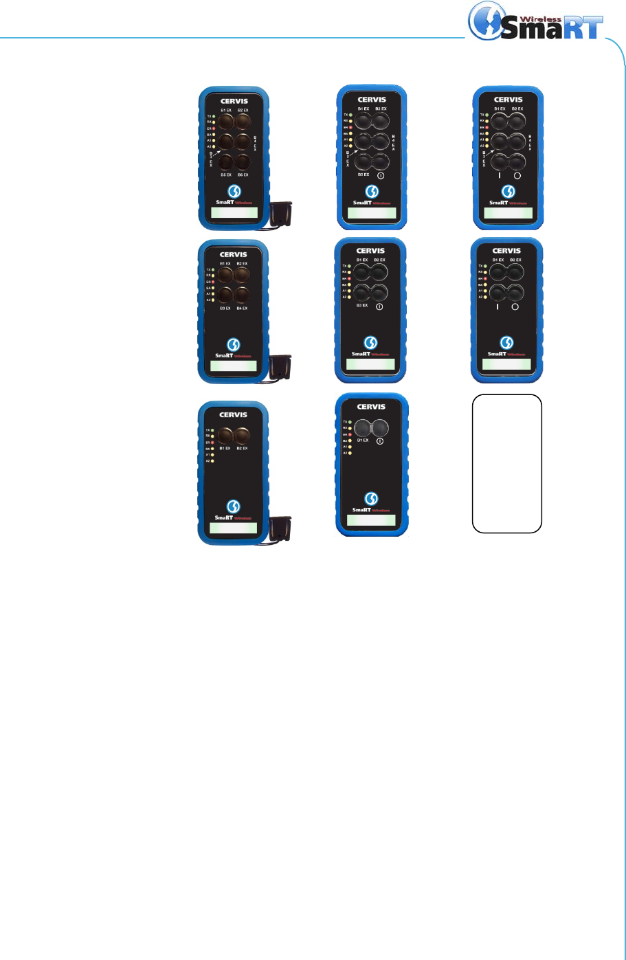
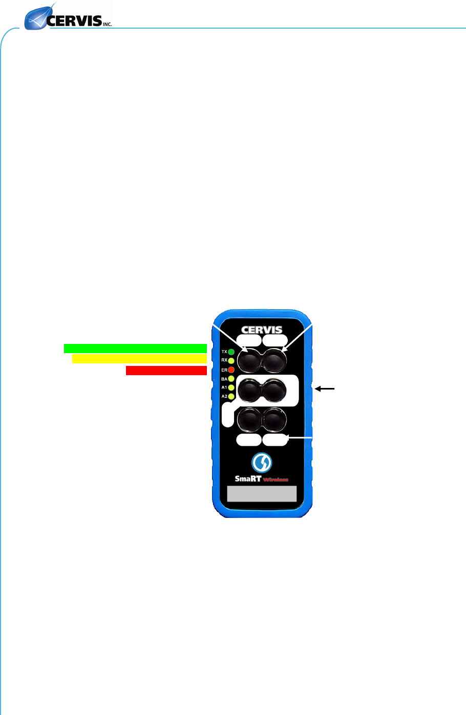
Figure 1. HH-xH06 6-LED Handheld Remote Button Assignments
A handheld can communicate to a variety of SmaRT base units and is used to provide up to six
command functions using direct sequence spread spectrum (DSSS) wireless technology at
2.4GHz or 900MHz. It provides a robust link with a base unit in congested radio environments.
SmaRT handheld units feature seamless association to SmaRT base units without the need to
open either the handheld or base unit cases.
The weatherproof handheld enclosure is constructed of rugged high-impact polymer with a
polycarbonate face plate securely sealed and attached by eight screws. It is further protected by
a removable rubber bumper that covers the back and sides of the unit extending beyond the
recessed faceplate. A convenient lanyard is provided that can be attached to the unit through a
recess on the bottom of the rubber bumper.
SmaRT handhelds operate between +3.6 to 4.5 VDC powered by three (3) size AAA alkaline
batteries. Six visible status/diagnostic LEDs (see Figure 2) indicate transmit and receive status,
errors, button press and output control, low battery warning, and low battery auto-shutdown of
the unit, as well as two additional indicators under control of a base unit.
PTO
DO
OO
Six Button Units
Four Button Units
Two Button Units
N/A

SmaRT HH-xH06
U076.0.4-SmaRT_HP-2/4/6_hhr
4
Figure 2. Standard PTO Six button Example
Notice in the example above that standard 6-button handheld pushbuttons are assigned to
specific SmaRT base unit outputs. This button layout applies to the two button and four button
PTO units where:
• Pushbutton outputs 1 and 2 apply to two button units.
• Pushbutton outputs 1 through 4 apply to four button units.
• Associate and Dissociate buttons are factory-selectable and apply to all PTO handheld
remotes.
1.1 DO and OO Button Operation
DO (Dual Operation) and OO (dedicated ON, dedicated OFF) handheld remotes provide the
advantage of more control when the handheld remote is powered ON and OFF. A DO-206, for
instance, can have one of the six buttons—Button 6—dedicated as an ON/OFF (toggle) that
when pressed once turns the unit ON, and when pressed again turns the unit OFF. In the case
of an OO handheld—OO-206 for instance—Button 5 can be dedicated as an ON button while
Button 6 can be dedicated as an OFF button. See the examples in Figure 1 for DO and OO
button placements.
ASSOCIATE (button 1)
DISSOCIATE
(button 2)
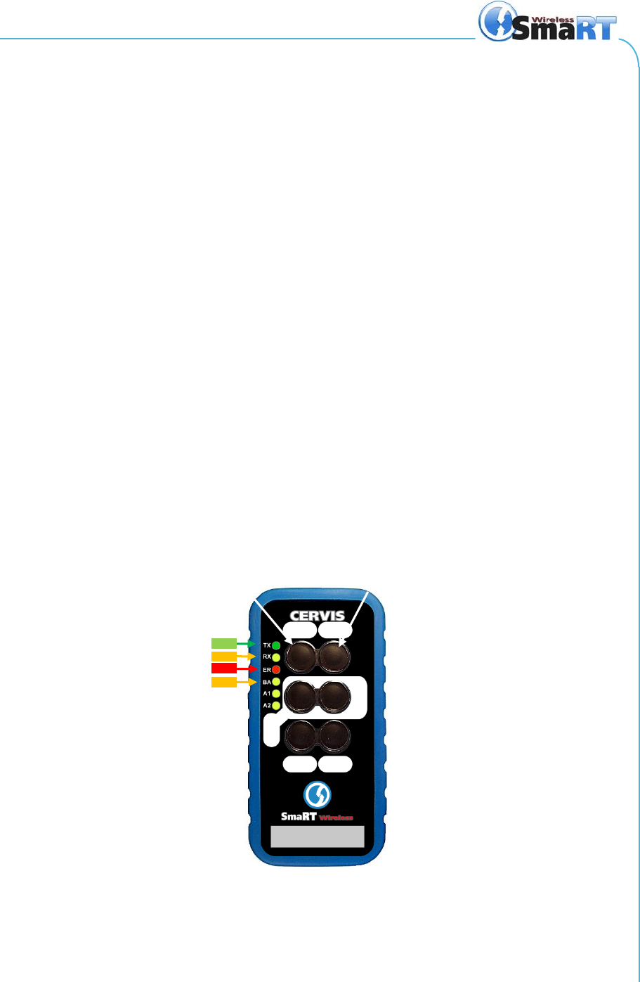
TX blinking Green when transmitting
RX blinking Yellow when receiving
ER blinking Red when error occurs
Protective Bumper
Out 5
Out 3
Out 4
Out 6
Out 2
BA blinking Yellow when Low Battery
A1 (Axillary 1) Custom program use
A2 (Axillary 2) Custom program use
Out 1
Handheld Remotes Manual
2013 Cervis, Inc.
5
2.0 Associate Handheld to Base Unit
Each SmaRT handheld must first establish a communication link with the base unit before the
base unit will recognize the handheld unit. This process is called Associate and it applies to all
HH-xH06 handhelds. A handheld remote as part of a system is associated to the system base
unit before leaving Cervis. In situations where it is necessary to re-establish handheld to base
unit communications, the following steps are used:
1. Remove power from the base unit and turn off (PTO – time out) the hand-held device.
2. Stand near the base unit in unobstructed, clear line-of-sight with the handheld in hand.
3. Simultaneously press and hold the Associate (B1) and Dissociate (B2) buttons. RX and ER
light.
4. Continue to hold both buttons until TX and RX light steady.
5. When TX and RX light, release B1 and B2. ER and BA light.
Note: If the next button press is not immediately performed (approximately 2sec.), all LEDs
flash and the Associate procedure is aborted. The process must be started anew to establish
the communication link.
6. Immediately press and hold the Associate button (B1). All LEDs light.
7. TX begins to slowly blink. Continue to hold B1.
8. Apply power to the base unit.
The handheld and base unit begin to establish a communication link while the Associate button
is held. Once the process is complete, all LEDs light briefly and then go out.
9. Release the Associate button.
The SmaRT System is ready for use with that particular handheld remote.
Figure 3. Handheld Buttons
ASSOCIATE
TX
RX
ER
DISSOCIATE
B1
B2
BA

SmaRT HH-xH06
U076.0.4-SmaRT_HP-2/4/6_hhr
6
3.0 Dissociate Handheld from Base Unit
In some circumstances it may become necessary to break the communication link, or dissociate
a handheld and a base unit. The Dissociate procedure is almost identical to the Associate
procedure, except the Dissociate button is used and held throughout the process instead of the
Associate button.
Using the following steps will break all previously established handheld remote
links. It will be necessary to perform the Associate Procedure (2.0 above) using
each handheld to re-establish communication links with a base unit.
1. Remove power from the base unit and turn off (PTO – time out) the hand-held
device.
2. Stand near the base unit in unobstructed, clear line-of-sight with the handheld in
hand.
3. Simultaneously press and hold the Associate (B1) and Dissociate (B2) buttons.
RX and ER light.
4. Continue to hold both buttons until TX and RX light steady.
5. When TX and RX light, release B1 and B2. ER and BA light.
Note: If the next button press is not immediately performed (approximately 1sec.), all LEDs
flash and the Associate procedure is aborted. The process must be started anew to establish
the communication link.
6. Immediately press and hold the Dissociate button (B2).
7. TX begins to slowly blink. Continue to hold B2.
8. Apply power to the base unit.
All established links with the base unit are removed. The SmaRT base unit will not communicate
with any handheld remote units. A handheld remote must use the Associate Procedure (2.0) to
re-establish a communication link with the base unit.
Handheld Remotes Manual
2013 Cervis, Inc.
7
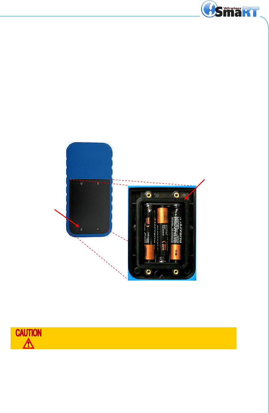
4.0 Battery Installation or Change
SmaRT HH-xH06 handheld units are powered by three size AAA alkaline batteries. When
installing batteries, be sure to observe proper polarity as marked on the inside of the
compartment to avoid damaging the unit. To replace or install batteries in the handheld:
1. Remove the four small Phillips screws from the Battery Compartment cover and
lift the cover from the handheld.
2. If installing batteries in an empty battery compartment, install three fresh size
AAA batteries. Be sure to position the batteries as shown in Figure 4 below.
3. If replacing expired batteries, remove the old batteries and install three fresh size
AAA batteries. Be sure to position the batteries as shown in Figure 4 below.
4. Replace the compartment cover and tighten the four Phillips screws. These
screws should not be over-tightened, but they should be tight enough to assure
the gasket provides a proper seal.
Figure 4. Handheld Battery Installation
Note: Cover screws must be tightened enough to ensure the sealing gasket is compressed.
Do not over-tighten the screws.
Be sure to observe proper polarity when placing batteries in the
handheld battery compartment.
Sealing gasket
Cover
screw
SmaRT HH-xH06
U076.0.4-SmaRT_HP-2/4/6_hhr
8
5.0 Using a Standard SmaRT Handheld Remote
Note: 3-LED handheld units use the same button sequence as 6-LED remotes.
Handheld control is achieved under the following conditions:
1. Communication between the handheld and base unit must be established using
the Associate Procedure (2.0).
1. You must be line of sight of the base unit while holding the handheld, within
approximately 300-1000 ft. (100-333m) of the unit.
2. Each button is Push-To-Operate (PTO). Each is dedicated to its assigned (or
hardwired) output driven by the base unit. The output is only controlled when the
appropriate button is pressed and held.
The front panel of SmaRT HH-xH06 handheld remotes respectively have two (2), four (4), or six
(6) buttons; all have three (3) diagnostic LEDs. Buttons 1 and 2 have dual functions used to
Associate and Dissociate the handheld to base units as previously described. Each button has
an area adjacent to it in which you can use a pen or a marker to write an Identifier for the button.
Output buttons control a particular base unit output only for as long as the button is pressed and
held. Output buttons are assigned as shown in the tables shown in Heading 5.4 for the particular
types of SmaRT handheld remotes.
Figure 5. PTO-906 and PTO-206 Front Panel
5.1 PTO Start and Stop
A standard PTO handheld remote activates (powers up) when any pushbutton is pressed.
Blinking TX and RX LEDs indicate that the remote is alive and communicating with the base unit.
To conserve battery power, the PTO unit stays active for approximately three (3) seconds and
will automatically power down unless there is button activity within the three second limit. When
the unit times out and powers down, all LED activity stops.
ASSOCIATE (button 1)
DISSOCIATE (button 2)
TX blinking Green when transmitting
RX blinking Yellow when receiving
ERROR blinking Red
Protective Bumper
5
3
Out 1
4
Out 6
2
Writable Identifier

Handheld Remotes Manual
2013 Cervis, Inc.
9
5.2 DO Start/Stop
A standard DO handheld remote has a designated button that when pressed powers the
handheld, and when pressed again powers down the unit. Blinking TX and RX LEDs indicate
that the remote is alive and communicating with the base unit when the unit is ON.
The standard DO handheld remote auto-shutdown is set to four (4) minutes of button inactivity
(default). To conserve battery power, unless there is button activity within the four minute limit,
the DO handheld remote automatically powers down. When the unit times out and powers down,
all LED activity stops.
5.3 OO Start and Stop
A standard OO handheld remote has a ON and a designated OFF button that when pressed
powers and powers-down the handheld respectively. Blinking TX and RX LEDs indicate that the
remote is alive and communicating with the base unit when the unit is ON.
The OO handheld remote auto-shutdown is set to four (4) minutes of button inactivity (default).
To conserve battery power, unless there is button activity within the four minute limit, the OO
handheld remote automatically powers down. When the unit times out and powers down, all LED
activity stops.
5.4 Pushbutton Output Assignments and Output Control
As a PTO, action will only occur when a pushbutton is pressed, and the duration of the action
only occurs for the length of time that the button is held down. Once the system is operating, the
pushbuttons are assigned to particular base unit outputs as shown in the following tables.
Table 2. PTO Button Output Assignments (X = 2 or 9)
Applies to PTO Type
Pushbutton
Output
ON
OFF
x06, x04, x02 1 1
Any button
press 3-second timeout
(default)
x06, x04, x02 2 2
x06, x04 3 3
x06, x04 4 4
x06 5 5
x06 6 6
Table 3. DO Button Output Assignments (x = 2 or 9)
Applies to DO Type
Pushbutton
Output
Unit ON/OFF
x06, x04, x02 1 1
x06, x04, x02 2 2 (N/A for x02) ON/OFF for DO-x02
x06, x04 3 3
x06, x04 4 4 (N/A for x04) ON/OFF for DO-x04
x06 5 5
x06 6 N/A ON/OFF for D0-x06

SmaRT HH-xH06
U076.0.4-SmaRT_HP-2/4/6_hhr
10
Table 4. OO Button Output Assignments (x = 2 or 9)
Applies to OO Type
Pushbutton
Output
ON or OFF
x06, x04 1 1
x06, x04 2 2
x06, x04 3 3 (N/A for x04) ON for x04
x06, x04 4 4 (N/A for x04) OFF for x04
x06 5 N/A ON for x06
x06 6 N/A OFF for x06
Handheld Remotes Manual
2013 Cervis, Inc.
11
6.0 Low Battery and Low Battery Auto-Shutdown
Note: Low Battery and Low Battery Auto-shutdown applies to all PTO, DO, and OO handheld
remotes, but because the Inactivity Timeout value (the set time within where there must be
button activity or the unit powers down) is so brief for PTOs, it is difficult to observe the Low
Battery and Low Battery Auto-Shutdown.
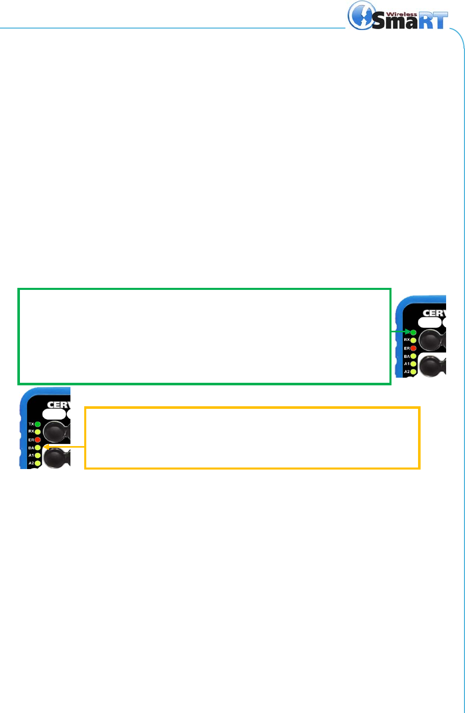
6.1 6-LED Remote Low Battery Warning
DO and OO Handheld Remotes
At 3.3VDC and below the Amber BA LED will begin to flash approximately once per second to
indicate a Low Battery Warning. Messages are still being transmitted, and the handheld can still
be used, but it is recommended that a fresh set of AAA batteries should be installed as soon as
possible.
At 3.2VDC the Yellow BA LED will turn on solid and the unit will begin a self powerdown. The
associated device will receive a low battery powerdown message.
PTO Handheld Remotes
Low Battery Warning on PTO handheld remotes can only be observed while a button is being
press.
Figure 6. 6-LED Remote Low Battery Warning and Auto-Shutdown
6.2 6-LED Remote Low Battery Auto-Shutdown
DO and OO Handheld Remotes
At 3.1VDC, the Green TX LED will cease to pulse, messages will not be sent or received, the
Amber BA LED will very briefly pulse once for approximately 1.25 seconds, and the handheld
remote will completely shut down. Subsequent attempts to use the handheld results in
immediate shut down of the unit. A fresh set of AAA batteries must be installed before the
handheld remote can be used.
PTO Handheld Remotes
Low Battery Auto-Shutdown is indicated on a PTO handheld remote only when a button is held
down, and then so briefly that it can be easily missed. Therefore, the more telling indication is
that the transmit (TX) and receive (RX) LEDs are inactive, and the Green TX LED is not
illuminated while any button is being held.
LOW BATTERY WARNING
At 3.3V or less, the TX LED stops flashing as messages are sent from the handheld remote to the
base unit. Messages are still being sent, but they are not indicated by the LED.
TX LED begins flashing once per second indicating a LOW BATTERY (3.3V or less) situation is
present. Three fresh AAA batteries should be replaced as soon as possible. The LED will continue
to flash at one second intervals unit the batteries are changed, or until the voltage level drops to
1.1V and Auto-Shutdown occurs.
LOW BATTERY AUTO-SHUTDOWN
At 3.1V, the Green TX LED stops flashing. The Amber BA LED flashes briefly, for
approximately 1.25 seconds, and the handheld remote automatically shuts down.
Three fresh AAA batteries must be installed before the handheld can be used again.

SmaRT HH-xH06
U076.0.4-SmaRT_HP-2/4/6_hhr
12
7.0 Specifications
Table 5. SmaRT HH-Xh06 Handheld Specifications
Item
Description
Power Vin +3.6V to +4.5V
Batteries Three (3) AAA alkaline
Auto-shutdown PTO – three (3) seconds of button inactivity
DO and OO – four (4) minutes of button inactivity
Low Battery Warning 3.3V and below
Low Battery Shutdown 3.2V
Environment Operating Temp -20°C to 55°C (-4°F to 131°F)
Storage Temp -40°C to 55°C (-40°F to 131°F)
Humidity 0 to 100%
Radio Frequency 906-924MHz or 2405-2480MHz
RF Power 900MHz @ 10mW ; 2.4GHz @ 100mW
License License free
Modulation DSSS
Antenna Internal
Enclosure Dimensions mm: 136.38 x 68.96 x 28.42
Inches: 5.37 x 2.68 x 0.92
Total Weight 200 gr./7.2 oz. (with lanyard)
Durability High Impact Polymer case
Polycarbonate faceplate
Impact absorbing bumper
LED Indicators (6) TX (Green) Transmit – Flashes when transmitting message
RX (Amber) Receive – Flashes when receiving message
ER (Red) Error – Blinks when error detected
BA (Amber) Low battery – Blinks when battery voltage ≤ 3.3V
A1 (Amber) Aux 1 – Custom use only
A2 (Amber) Aux 2 – Custom use only
Buttons Two, Four, or Six Pushbuttons
Number of Functions Handheld type dependent, see Heading 5.4
Style Push-to-operate
Button Life 5-million operations (typical)
Umbilical Not Applicable
Display Not Applicable
Proportional Inputs Not Applicable
Handheld Remotes Manual
2013 Cervis, Inc.
13
8.0 Spare Parts List
Table 6. Spare Parts List
Item
Cervis Bin Location
Protective Rubber Bumper AA6-02
Lanyard AA8-01B
Battery Cover with 4 Screws Call Cervis @ 724-741-9000
AAA 1.5V Alkaline Batteries (pk. 3) AA6-03
Belt Clip AA5-07
Replacement Antenna Disallowed

SmaRT HH-xH06
U076.0.4-SmaRT_HP-2/4/6_hhr
14
Appendix A: HH-x06 Product Variation List
Table 7. HH-x06 Product Variation List
Model Model # Frequency RF Power Activation
Discrete
Pushbutton
Inputs
Dedicated
Stop Attachment
PTO-9H06 07116550 900MHz 10mW Any Input 6 No Lanyard
PTO-9H04 07116551 900MHz 10mW Any Input 4 No Lanyard
PTO-9H02 07116552 900MHz 10mW Any Input 2 No Lanyard
OO-9H06 07116553 900MHz 10mW ON,OFF 6 Yes Lanyard
OO-9H04 07116554 900MHz 10mW ON,OFF 4 Yes Lanyard
OO-9H02 07116555 900MHz 10mW ON,OFF 2 Yes Lanyard
DO-9H06 07116556 900MHz 10mW ON/OFF 6 Yes Lanyard
DO-9H04 07116557 900MHz 10mW ON/OFF 4 Yes Lanyard
DO-9H02 07116558 900MHz 10mW ON/OFF 2 Yes Lanyard
PTO-9H06S 07116559 900MHz 10mW Any Input 6 No Lanyard
OO-9H06S 07116560 900MHz 10mW ON,OFF 6 Yes Lanyard
DO-9H06S 07116561 900MHz 10mW ON/OFF 6 Yes Lanyard
PTO-9H06B 07116562 900MHz 10mW Any Input 6 No Belt Clip
PTO-9H04B 07116563 900MHz 10mW Any Input 4 No Belt Clip
PTO-9H02B 07116564 900MHz 10mW Any Input 2 No Belt Clip
OO-9H06B 07116565 900MHz 10mW ON,OFF 6 Yes Belt Clip
OO-9H04B 07116566 900MHz 10mW ON,OFF 4 Yes Belt Clip
OO-9H02B 07116567 900MHz 10mW ON,OFF 2 Yes Belt Clip
DO-9H06B 07116568 900MHz 10mW ON/OFF 6 Yes Belt Clip
DO-9H04B 07116569 900MHz 10mW ON/OFF 4 Yes Belt Clip
DO-9H02B 07116570 900MHz 10mW ON/OFF 2 Yes Belt Clip
PTO-2H06 07126550 2.4GHz 100mW Any Input 6 No Lanyard
PTO-2H04 07126551 2.4GHz 100mW Any Input 4 No Lanyard
PTO-2H02 07126552 2.4GHz 100mW Any Input 2 No Lanyard
OO-2H06 07126553 2.4GHz 100mW ON,OFF 6 Yes Lanyard
OO-2H04 07126554 2.4GHz 100mW ON,OFF 4 Yes Lanyard
OO-2H02 07126555 2.4GHz 100mW ON,OFF 2 Yes Lanyard
DO-2H06 07126556 2.4GHz 100mW ON/OFF 6 Yes Lanyard
DO-2H04 07126557 2.4GHz 100mW ON/OFF 4 Yes Lanyard
DO-2H02 07126558 2.4GHz 100mW ON/OFF 2 Yes Lanyard
PTO-2H06S 07126559 2.4GHz 100mW Any Input 6 No Lanyard
OO-2H06S 07126560 2.4GHz 100mW ON,OFF 6 Yes Lanyard
DO-2H06S 07126561 2.4GHz 100mW ON,OFF 6 Yes Lanyard
PTO-2H06B 07126562 2.4GHz 100mW Any Input 6 No Belt Clip
PTO-2H04B 07126563 2.4GHz 100mW Any Input 4 No Belt Clip
PTO-2H02B 07126564 2.4GHz 100mW Any Input 2 No Belt Clip
OO-2H06B 07126565 2.4GHz 100mW ON,OFF 6 Yes Belt Clip
OO-2H04B 07126566 2.4GHz 100mW ON,OFF 4 Yes Belt Clip
OO-2H02B 07126567 2.4GHz 100mW ON,OFF 2 Yes Belt Clip
DO-2H06B 07126568 2.4GHz 100mW ON/OFF 6 Yes Belt Clip
DO-2H04B 07126569 2.4GHz 100mW ON/OFF 4 Yes Belt Clip
DO-2H02B
07126570
2.4GHz
100mW
ON/OFF
2
Yes
Belt Clip
Handheld Remotes Manual
2013 Cervis, Inc.
15
Appendix B: Exposure to Radio Frequency Energy
SmaRT handheld remote units contain radio transceivers. When active, handheld remotes send
out radio frequency (RF) energy through its internal antenna.
For optimal performance and to ensure that human exposure to RF energy does not exceed the
recommended guidelines, always follow these instruction and precautions: When using the
handheld remote, hold the remote so that the top buttons are away from the body in the direction
of the base unit. Keep the remote when in use at least 15mm (5/8 inch) away from the body, and
only use carrying cases, belt clips, or holders that are approved by the Cervis, Inc.
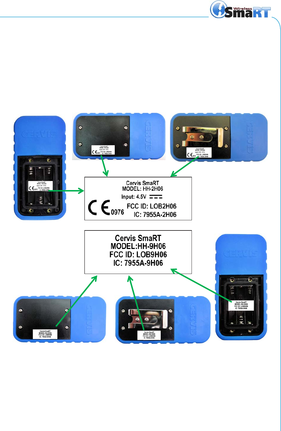
Appendix C: Agency Identification Label Locations
Figure 7. Agency Identification Label Locations