Cervis SBU900 Direct Sequence Spread Spectrum User Manual U007 0 SmaRT902 system R amd
Cervis Inc. Direct Sequence Spread Spectrum U007 0 SmaRT902 system R amd
UserManual.wiki
>
Cervis
>
SBU900 User Manual
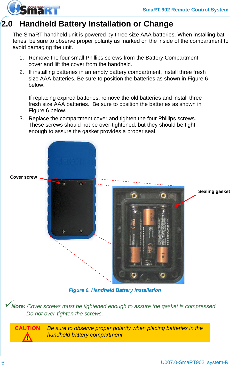
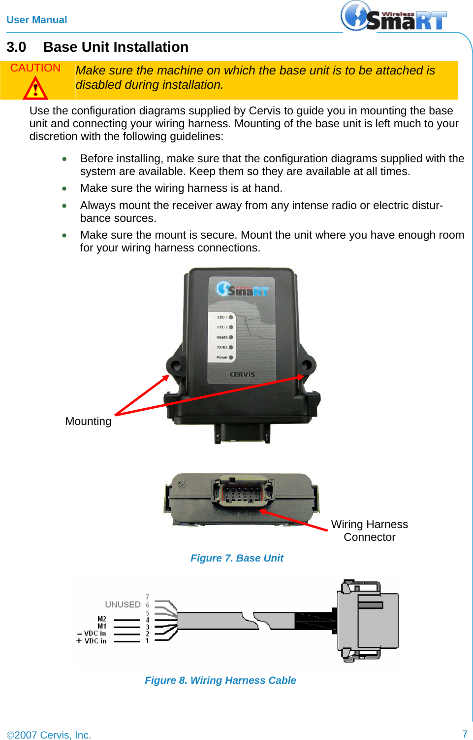
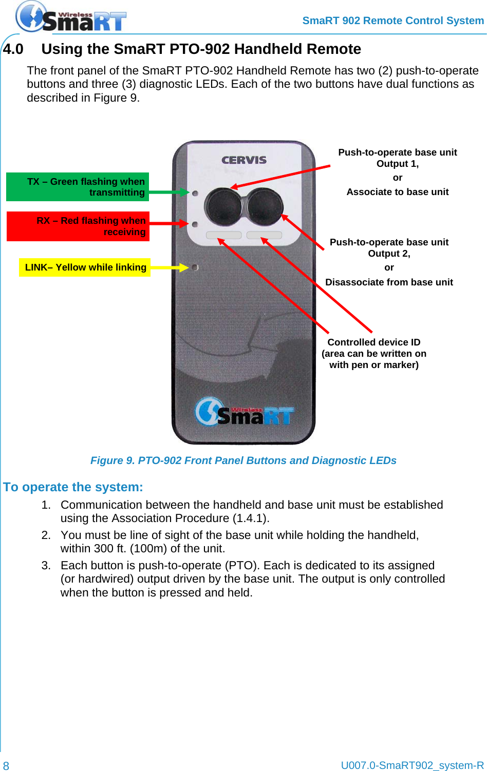
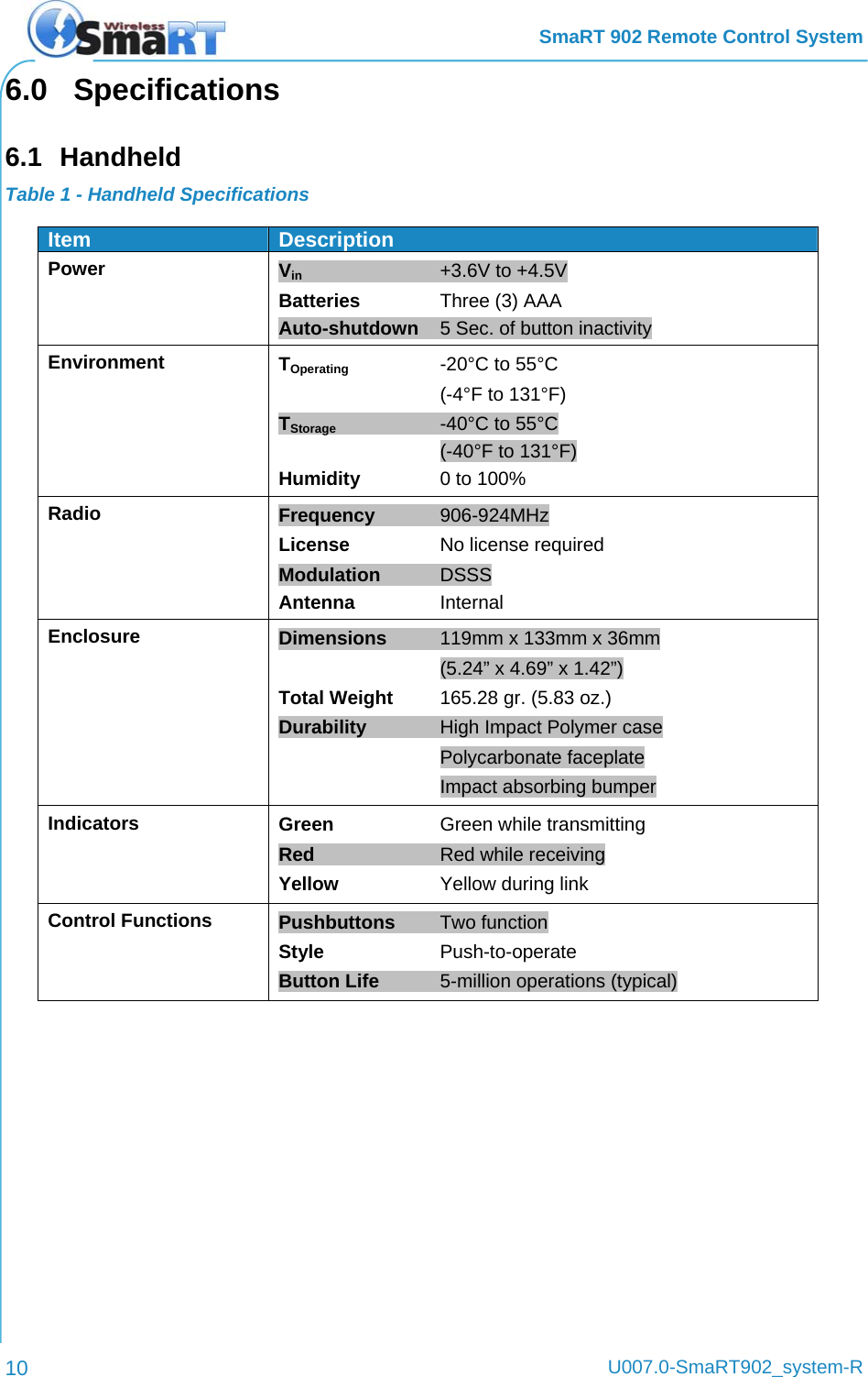
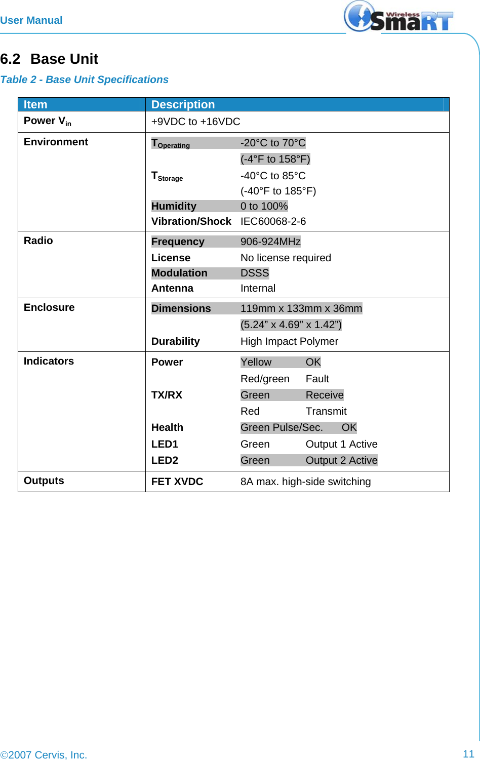
User Manual
Navigation menu
Upload a User Manual
Namespaces
Wiki Guide
HTML
PDF
Info
Views
User Manual
Discussion / Help
Navigation