Cervis SBU900 Direct Sequence Spread Spectrum User Manual U007 0 SmaRT902 system R amd
Cervis Inc. Direct Sequence Spread Spectrum U007 0 SmaRT902 system R amd
Cervis >
User Manual

It2 ©2007 Cervis, Inc.
SmaRT 902
Remote Control System
Manual
U007.0-SmaRT902_system-R

SmaRT Remote Control System
Cervis, Inc.
Visit our Web site at: www.cervisinc.com
© 2007 Cervis, Inc. All rights reserved. Content is subject to change without notice.
This document is the property of Cervis, Inc. and cannot be copied, modified,
or reproduced without the express prior written consent of Cervis, Inc.
Cervis, Inc. reserves the right to change this manual or edit, delete, or modify
any information without prior notification.
FCC Statements
15.19 – Two Part Warning
This device complies with Part 15 of the FCC rules. Operation is subject to the follow-
ing two conditions:
(1) This device may not cause harmful interference and
(2) This device must accept any interference received, including interference that
may cause undesired operation.
15.21 – Unauthorized Modification
NOTICE: The manufacturer is not responsible for any unauthorized modifications to
this equipment made by the user. Such modifications could void the user’s authority
to operate the equipment.

User Manual
©2007 Cervis, Inc. i
Contents
FCC Statements ............................................................................................................................ i
1.0 SmaRT 902 Remote Control System.................................................................................. 1
1.1 Features............................................................................................................................. 1
1.2 PT0-902 Handheld Remote .............................................................................................. 2
1.3 BU-902F Base Unit............................................................................................................ 2
1.4 Communication Configuration Options ......................................................................... 3
1.4.1 Associate Handheld to Base Unit Procedure............................................................... 3
1.4.2 Disassociate Handheld to Base Unit Procedure .......................................................... 4
2.0 Handheld Battery Installation or Change .......................................................................... 6
3.0 Base Unit Installation ..........................................................................................................7
4.0 Using the SmaRT PTO-902 Handheld Remote.................................................................. 8
To operate the system:................................................................................................................ 8
5.0 Wiring Harness..................................................................................................................... 9
6.0 Specifications..................................................................................................................... 10
6.1 Handheld.......................................................................................................................... 10
6.2 Base Unit ......................................................................................................................... 11
Figures
Figure 1. PTO-902 Handheld Remote and BU-902F Base Unit..................................................1
Figure 2. PTO-902 (without bumper)............................................................................................2
Figure 3. Female Twelve (12) Pin Connector...............................................................................3
Figure 4. BU-902F LEDs ................................................................................................................3
Figure 5. Handheld PTO Buttons..................................................................................................4
Figure 6. Handheld Battery Installation .......................................................................................6
Figure 7. Base Unit.........................................................................................................................7
Figure 8. Wiring Harness Cable....................................................................................................7
Figure 9. PTO-902 Front Panel Buttons and Diagnostic LEDs..................................................8
Tables
Table 1 - Handheld Specifications..............................................................................................10
Table 2 - Base Unit Specifications..............................................................................................11

SmaRT 902 Remote Control System
U007.0-SmaRT902_system-R
ii
Notes:
Product Name
©2007 Cervis, Inc.
1
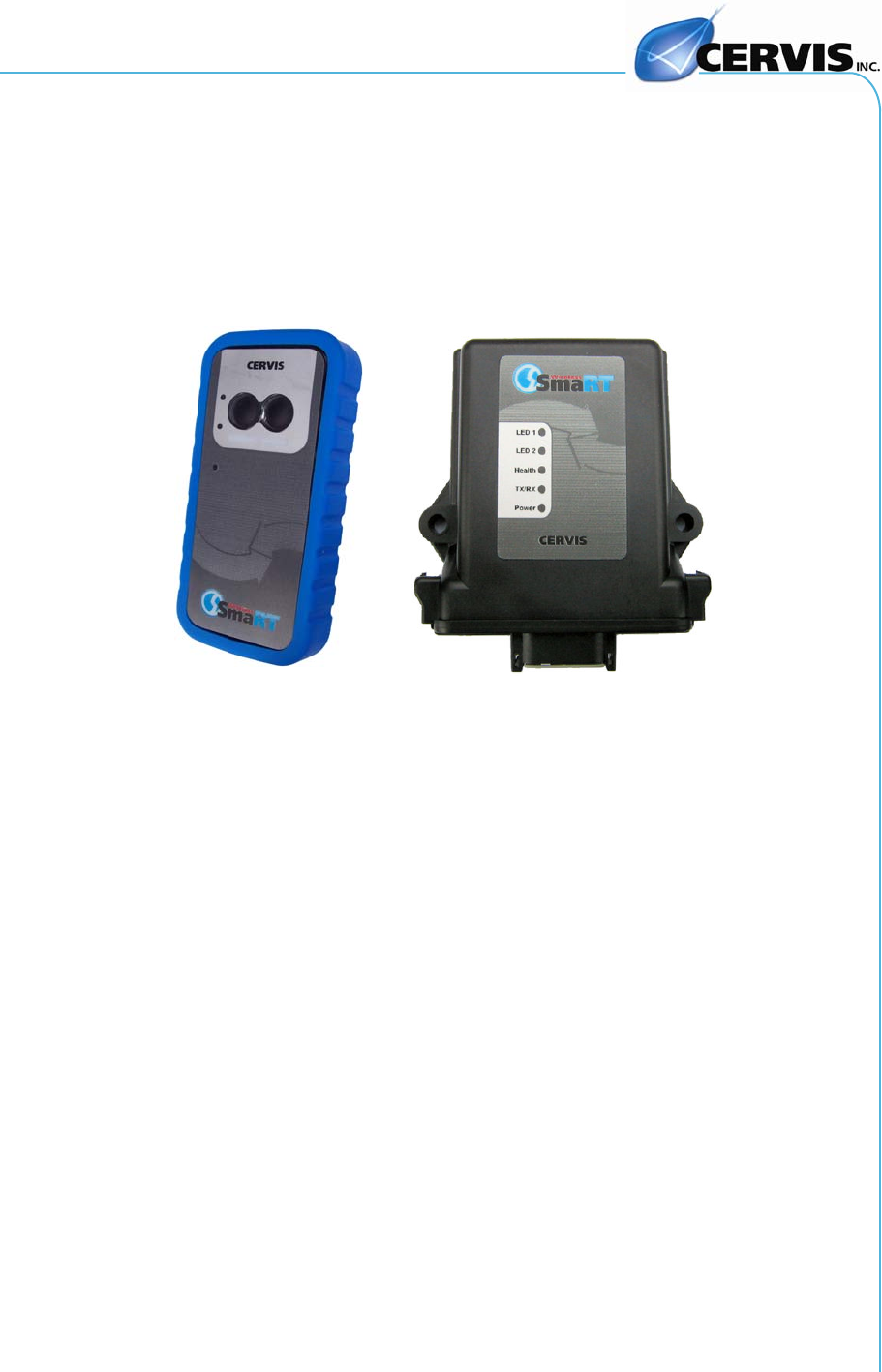
1.0 SmaRT 902 Remote Control System
The standard SmaRT 902 Remote Control System consists of a 2-button PTO-902
wireless handheld transmitter, a BU-902F base unit, and the wiring harness that is used
to connect the base unit to the controlled apparatus. A single base unit is capable of
communicating with up to eight PTO-902 Handheld units. The rugged construction,
compact size, and multiple output versatility allow for SmaRT Systems to be used for
many applications that require remote operation.
Figure 1. PTO-902 Handheld Remote and BU-902F Base Unit
1.1 Features
• IP65 Enclosure
• Operating Temp: -20°C to +55°C
• Storage Temp: -40°C to +85°C
• PTO-902 Handheld has two Push-to-Operate (PTO) buttons
• Handheld powered by three AAA Batteries (+3.6VDC to 4.5VDC)
• Base Unit +9VDC to +16VDC Input Power
• Two FET high side switching outputs (8A max.)
• License Free Frequency, 900MHz Spread Spectrum Technology
• 300’ (100m) Range
• Rugged high-impact polymer enclosure
• Removable rubber bumper (handheld)
• Lanyard
• Compact Weatherproof Design
• Five base unit and three handheld diagnostic LEDs
• Single connector interface for ease of wiring
SmaRT 902 Remote Control System
U007.0-SmaRT902_system-R
2
1.2 PT0-902 Handheld Remote
The SmaRT PTO-902 Handheld Remote features a 300’ handheld-to-base unit com-
munication range providing two function press-to-operate (PTO) control. Using direct
sequence spread spectrum (DSSS) wireless technology at 900MHz, the handheld unit
provides a robust link with a base unit in congested radio environments. SmaRT hand-
held units feature seamless association to a SmaRT BU-902F Base Unit without the
need to open either case.
The handheld enclosure is constructed of rugged high-impact polymer with a polycar-
bonate face plate securely sealed and attached by eight screws. It is further protected
by a removable rubber bumper that covers the back and sides of the unit extending be-
yond the recessed faceplate. A convenient lanyard that attaches to the remote is pro-
vided.
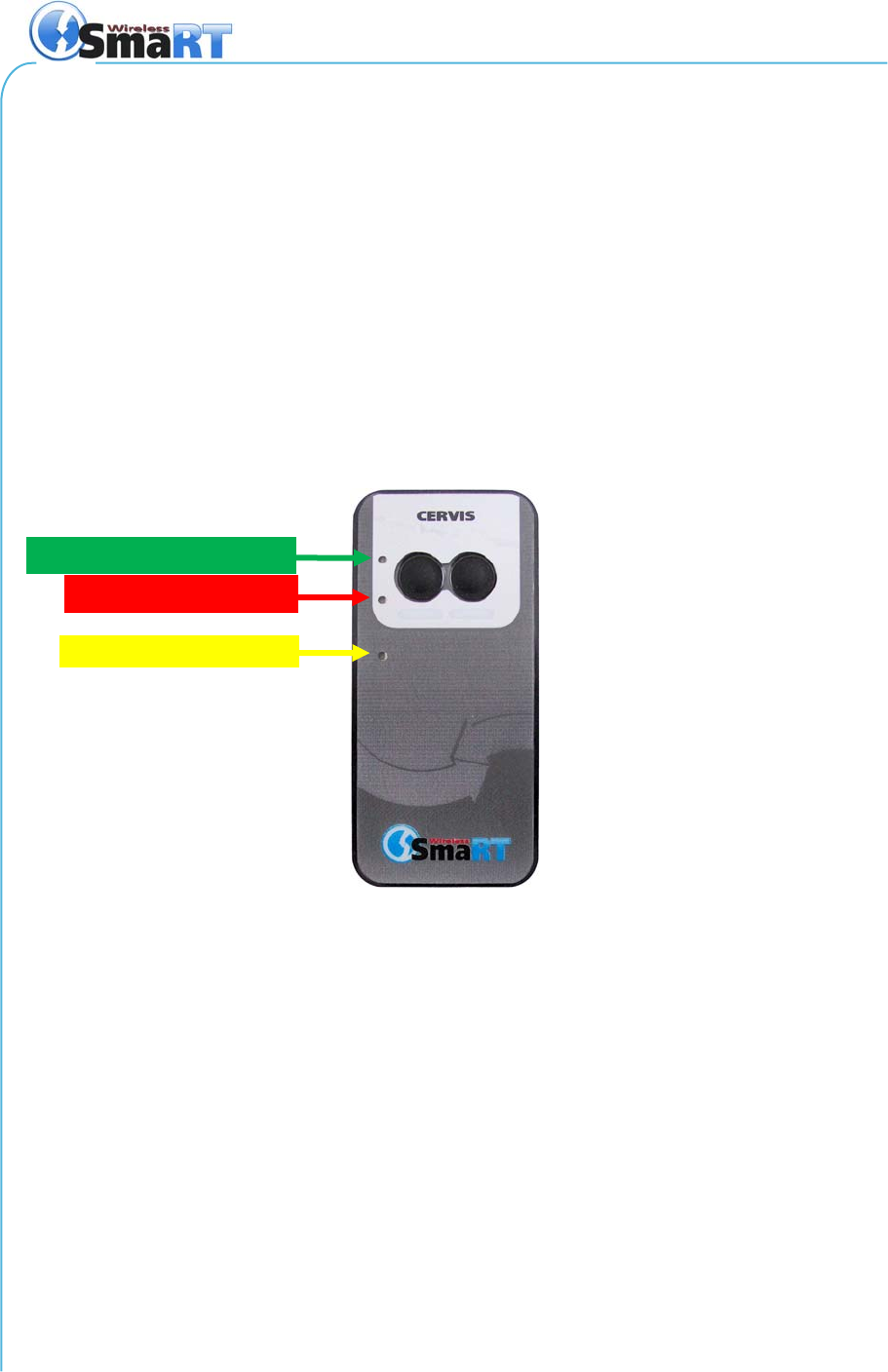
The handheld is powered by three size AAA batteries. Three status/diagnostic LEDs
are visible on the handheld faceplate as shown in Figure 2 below.
Figure 2. PTO-902 (without bumper)
1.3 BU-902F Base Unit
The SmaRT BU-902F Base Unit features two FET, 8A max high-side switching outputs.
It accepts an input power operating voltage range from +9 to +16VDC. Using Direct Se-
quence Spread Spectrum (DSSS) wireless technology at 900MHz, the base unit pro-
vides a robust link with a handheld in congested radio environments
SmaRT base units feature seamless association to a SmaRT handheld unit without the
need to open either the remote or base unit case. All controlled apparatus connections
to the base unit are made via a single cable.
The base unit compact enclosure is constructed of rugged, heavy duty high impact
plastic—the type commonly used by the automotive industry. VDC power to the unit
and output signals are ported via the heavy duty twelve (12) pin automotive-type con-
nector.
TX
–
Green when transmitting
RX
–
Red when
r
eceiving
LIN
K
–
Yellow while linkin
g
User Manual
©2007 Cervis, Inc. 3
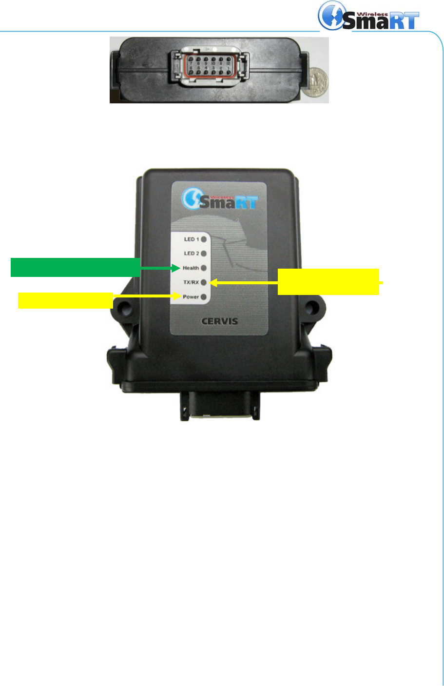
Figure 3. Female Twelve (12) Pin Connector
The unit has five status/diagnostic LEDs that are used to determine the state of the unit.
The LEDs are shown in Figure 4 below.
Figure 4. BU-902F LEDs
1.4 Communication Configuration Options
A standard SmaRT 902 System comes with one PTO-902 Handheld Remote and one
BU-902F Base Unit, but each base unit can establish communication with up to eight
PTO-902 Handheld Remotes. Each handheld must first establish a communications link
with the base unit before the base unit can recognize the handheld unit. This process is
called Association.
1.4.1 Associate Handheld to Base Unit Procedure
Use the following step to Associate a handheld remote to a base unit.
1. Remove power from the base unit.
2. Stand near the base unit in line of sight with the handheld in your hand.
3. Press and hold both buttons (see Figure 5). TX lights steady green.
4. Continue to hold both buttons for the five seconds it takes for the LINK
LED to begin flashing yellow.
TX/RX
–
Yellow when
transceivin
g
POWER OK
–
Yellow
Health OK
–
Green pulse/sec
SmaRT 902 Remote Control System
U007.0-SmaRT902_system-R
4
5. When LINK flashes yellow, release the two buttons. The RX button flash-
es red allowing two (2) seconds for you to make the next button press.
9
Note: If the next button press is not performed within the two second interval that RX
flashes red, the procedure is aborted and must be started anew to establish
the Association.
6. Press and hold the Associate button (See below). The RX extinguishes,
the TX lights steady green, and the LINK LED lights steady yellow.
7. Apply power to the base unit while continuing to hold the Associate but-
ton.
The base unit and handheld begin to Associate and establish a communications link.
Once the Association is complete, the yellow LINK led extinguishes, the RX begins
flashing red, and the TX lights steady green and remains so until the button is released.
8. Release the Associate button. The RX LED extinguishes, the TX LED
flashes green for a brief time, and then it too extinguishes.
The SmaRT 902 System is ready for use with that particular handheld remote.
Figure 5. Handheld PTO Buttons
1.4.2 Disassociate Handheld to Base Unit Procedure
In some circumstances it may become necessary to disassociate a handheld that is
linked to a base unit. The procedure to Disassociate handhelds from the base unit is
almost identical to the Associate procedure except the Disassociate button is used and
held throughout the process.
9
Note: The following procedure will Disassociate all remotes linked to the base unit.
CAUTION
Completion of the following steps will Disassociate all handheld
remote links previously established. It will be necessary to per-
form the Associate Procedure (1.4.1 above) using each handheld
to re-establish communication links with the base unit.
Yellow while linkin
g
ASSOCIATE
TO BASE UNIT DISASSOCIATE
FROM BASE UNIT

User Manual
©2007 Cervis, Inc. 5
1. Remove power from the base unit.
2. Stand near the base unit in line of sight with the handheld in your hand.
3. Press and hold both buttons (see Figure 5). TX lights steady green.
4. Continue to hold both buttons for the five seconds it takes for the LINK
LED to begin flashing yellow.
5. When LINK flashes yellow, release the two buttons. The RX button flash-
es red allowing two (2) seconds for you to make the next button press.
9
Note: If the next button press is not performed within the two second interval that RX
flashes red, the procedure is aborted and must be started anew to establish
the Association.
6. Press and hold the Disassociate button. (See Figure 5 above.) The RX
extinguishes, the TX lights steady green, and the LINK LED lights steady
yellow.
7. Apply power to the base unit while continuing to hold the Disassociate
button.
The base unit and all previously linked handhelds begin to Disassociate communica-
tions links. Once the Disassociation is complete, the yellow LINK led extinguishes, the
RX begins flashing red, and the TX lights steady green and remains so until the button
is released.
8. Release the Disassociate button. The RX LED extinguishes, the TX LED
flashes green for a brief time, and then it too extinguishes.
The SmaRT BU-902F Base Unit will not communicate with any handheld remote units.
A handheld remote must use the Association Procedure to re-establish a communica-
tion link with the base unit.
SmaRT 902 Remote Control System
U007.0-SmaRT902_system-R
6
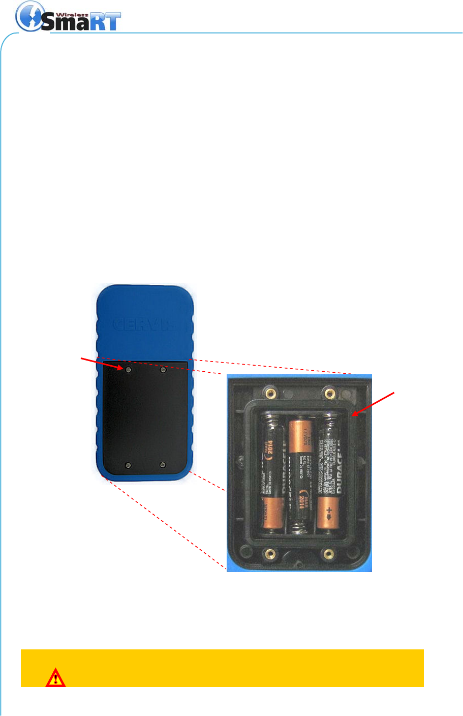
2.0 Handheld Battery Installation or Change
The SmaRT handheld unit is powered by three size AAA batteries. When installing bat-
teries, be sure to observe proper polarity as marked on the inside of the compartment to
avoid damaging the unit.
1. Remove the four small Phillips screws from the Battery Compartment
cover and lift the cover from the handheld.
2. If installing batteries in an empty battery compartment, install three fresh
size AAA batteries. Be sure to position the batteries as shown in Figure 6
below.
If replacing expired batteries, remove the old batteries and install three
fresh size AAA batteries. Be sure to position the batteries as shown in
Figure 6 below.
3. Replace the compartment cover and tighten the four Phillips screws.
These screws should not be over-tightened, but they should be tight
enough to assure the gasket provides a proper seal.
Figure 6. Handheld Battery Installation
9
Note: Cover screws must be tightened enough to assure the gasket is compressed.
Do not over-tighten the screws.
CAUTION
Be sure to observe proper polarity when placing batteries in the
handheld battery compartment.
Sealing gasket
Cover screw
User Manual
©2007 Cervis, Inc. 7
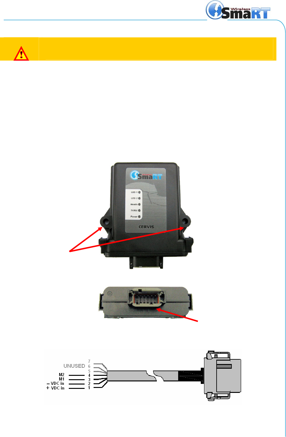
3.0 Base Unit Installation
CAUTION
Make sure the machine on which the base unit is to be attached is
disabled during installation.
Use the configuration diagrams supplied by Cervis to guide you in mounting the base
unit and connecting your wiring harness. Mounting of the base unit is left much to your
discretion with the following guidelines:
• Before installing, make sure that the configuration diagrams supplied with the
system are available. Keep them so they are available at all times.
• Make sure the wiring harness is at hand.
• Always mount the receiver away from any intense radio or electric distur-
bance sources.
• Make sure the mount is secure. Mount the unit where you have enough room
for your wiring harness connections.
Figure 7. Base Unit
Figure 8. Wiring Harness Cable
Mounting
Wiring Harness
Connector
SmaRT 902 Remote Control System
U007.0-SmaRT902_system-R
8
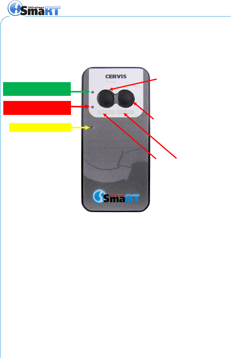
4.0 Using the SmaRT PTO-902 Handheld Remote
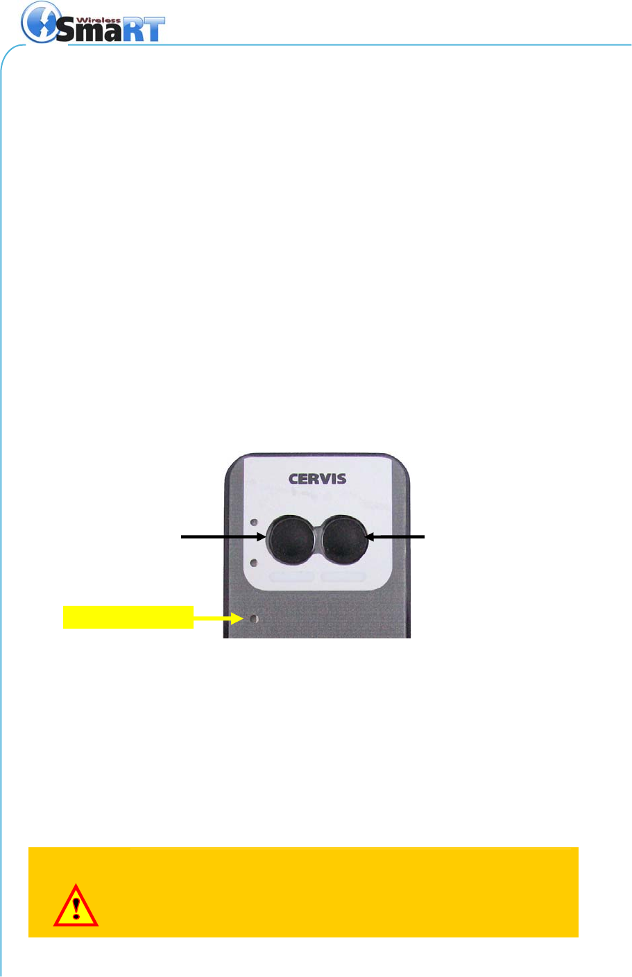
The front panel of the SmaRT PTO-902 Handheld Remote has two (2) push-to-operate
buttons and three (3) diagnostic LEDs. Each of the two buttons have dual functions as
described in Figure 9.
Figure 9. PTO-902 Front Panel Buttons and Diagnostic LEDs
To operate the system:
1. Communication between the handheld and base unit must be established
using the Association Procedure (1.4.1).
2. You must be line of sight of the base unit while holding the handheld,
within 300 ft. (100m) of the unit.
3. Each button is push-to-operate (PTO). Each is dedicated to its assigned
(or hardwired) output driven by the base unit. The output is only controlled
when the button is pressed and held.
Push-to-operate base unit
Output 1,
or
Associate to base unit
Push-to-operate base unit
Output 2,
or
Disassociate from base unit
Controlled device ID
(area can be written on
with pen or marker)
TX
–
Green flashing when
transmittin
g
RX
–
Red flashing when
r
eceivin
g
LIN
K
–
Yellow while linking
User Manual
©2007 Cervis, Inc. 9
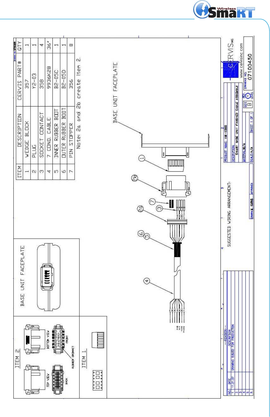
5.0 Wiring Harness
SmaRT 902 Remote Control System
U007.0-SmaRT902_system-R
10
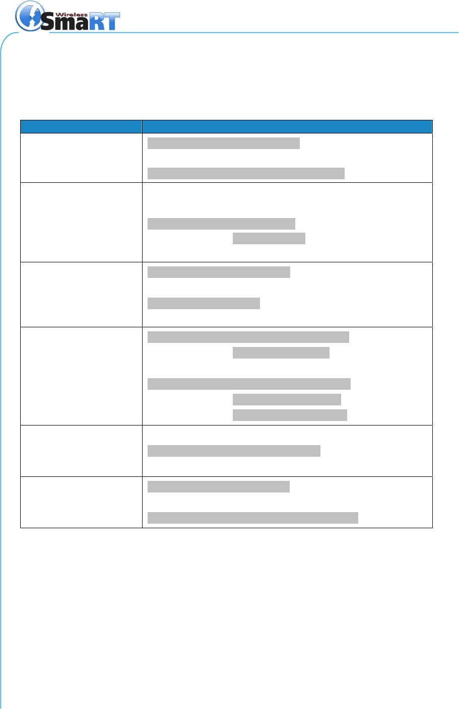
6.0 Specifications
6.1 Handheld
Table 1 - Handheld Specifications
Item Description
Power Vin +3.6V to +4.5V
Batteries Three (3) AAA
Auto-shutdown 5 Sec. of button inactivity
Environment
TOperating -20°C to 55°C
(-4°F to 131°F)
TStorage -40°C to 55°C
(-40°F to 131°F)
Humidity 0 to 100%
Radio Frequency 906-924MHz
License No license required
Modulation DSSS
Antenna Internal
Enclosure Dimensions 119mm x 133mm x 36mm
(5.24” x 4.69” x 1.42”)
Total Weight 165.28 gr. (5.83 oz.)
Durability High Impact Polymer case
Polycarbonate faceplate
Impact absorbing bumper
Indicators Green Green while transmitting
Red Red while receiving
Yellow Yellow during link
Control Functions Pushbuttons Two function
Style Push-to-operate
Button Life 5-million operations (typical)
User Manual
©2007 Cervis, Inc. 11
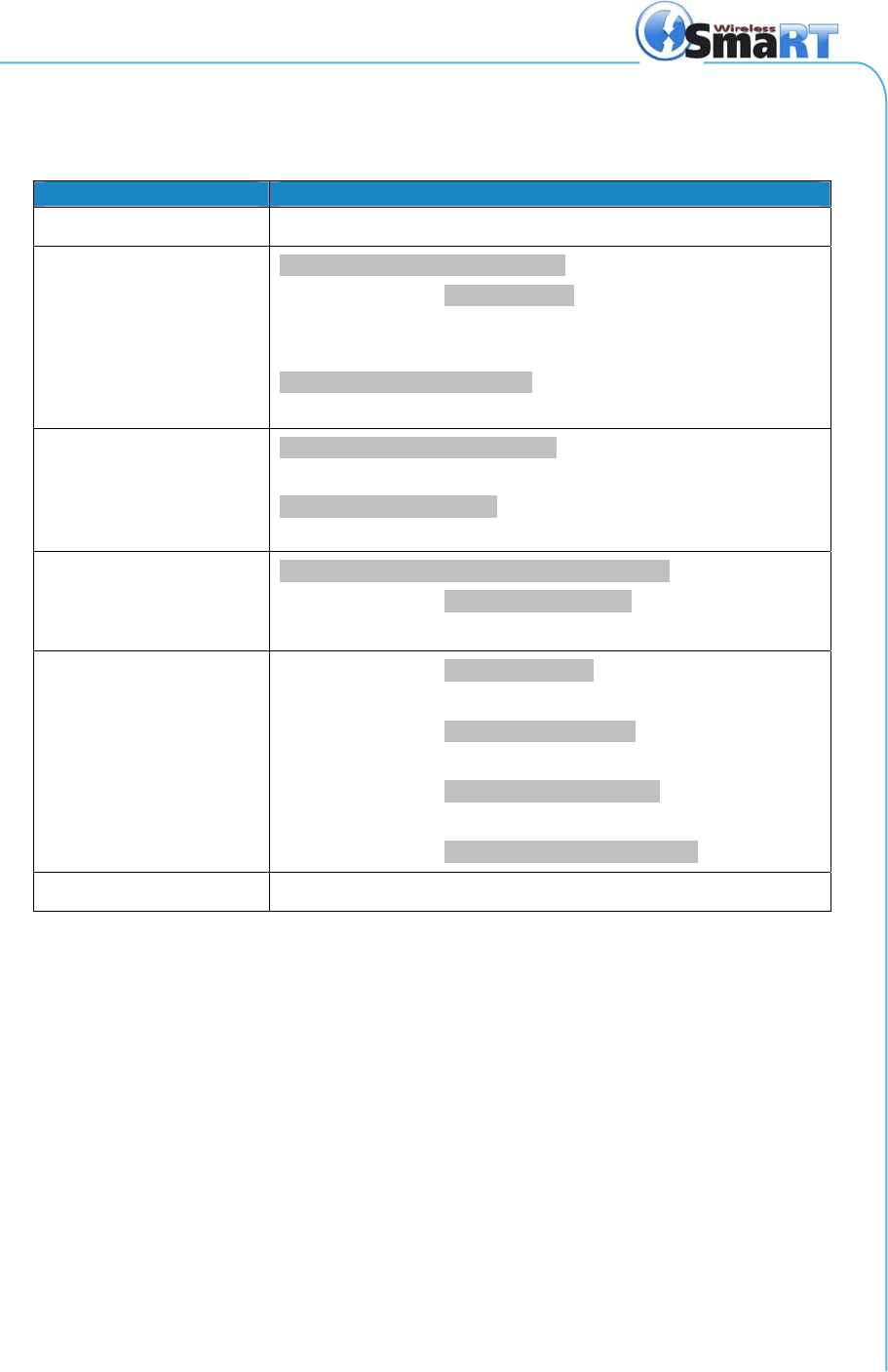
6.2 Base Unit
Table 2 - Base Unit Specifications
Item Description
Power Vin +9VDC to +16VDC
Environment
TOperating -20°C to 70°C
(-4°F to 158°F)
TStorage -40°C to 85°C
(-40°F to 185°F)
Humidity 0 to 100%
Vibration/Shock IEC60068-2-6
Radio Frequency 906-924MHz
License No license required
Modulation DSSS
Antenna Internal
Enclosure Dimensions 119mm x 133mm x 36mm
(5.24” x 4.69” x 1.42”)
Durability High Impact Polymer
Indicators Power Yellow OK
Red/green Fault
TX/RX Green Receive
Red Transmit
Health Green Pulse/Sec. OK
LED1 Green Output 1 Active
LED2 Green Output 2 Active
Outputs FET XVDC 8A max. high-side switching

©2007 Cervis, Inc. U007.0-SmaRT902_system-R
Cervis, Inc.
Visit our Web site at: www.cervisinc.com
The SmaRT Remote Control System is manufactured and distributed by Cervis, Inc.
© 2007 Cervis, Inc. All rights reserved. Content is subject to change without notice.