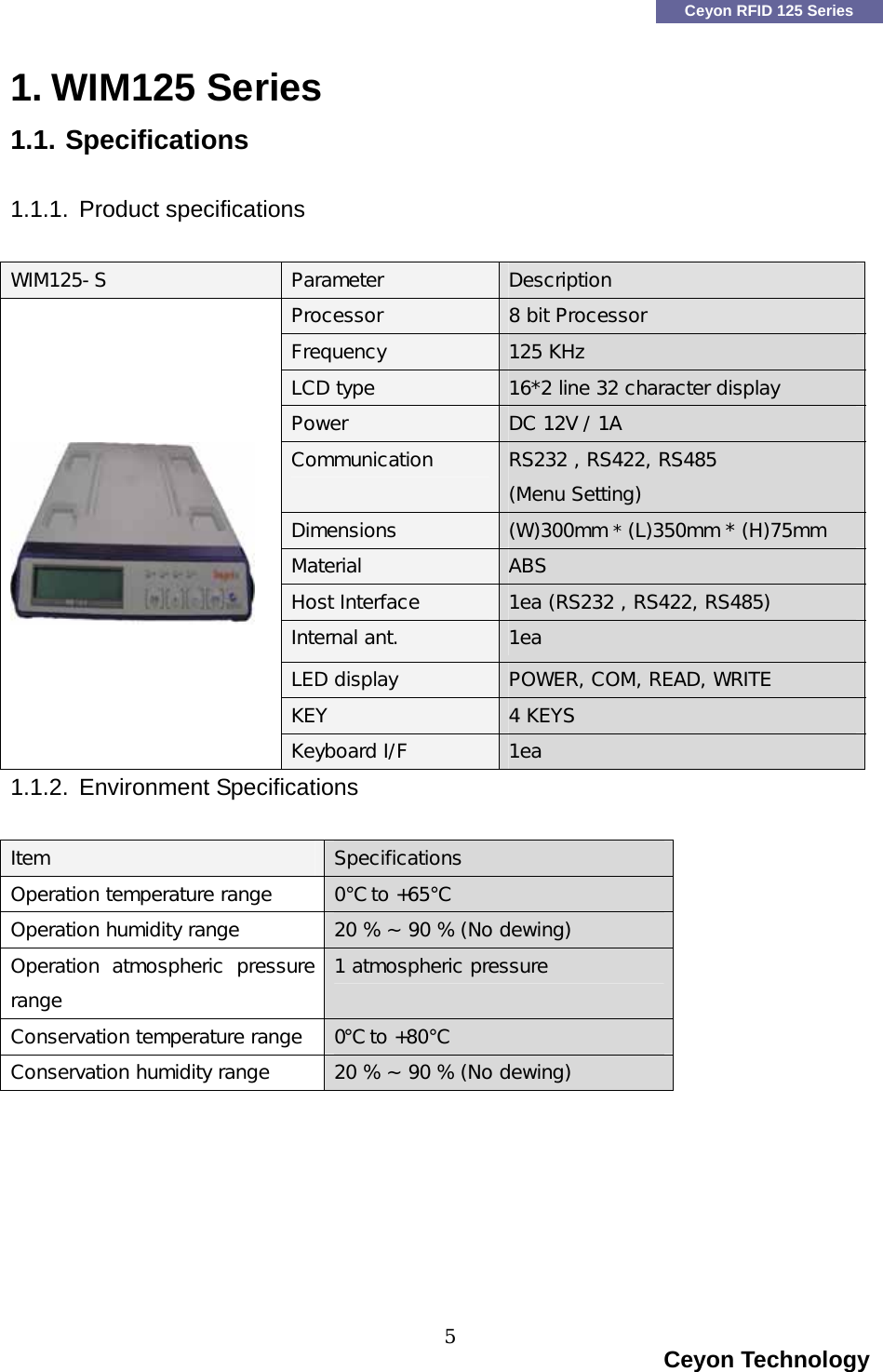
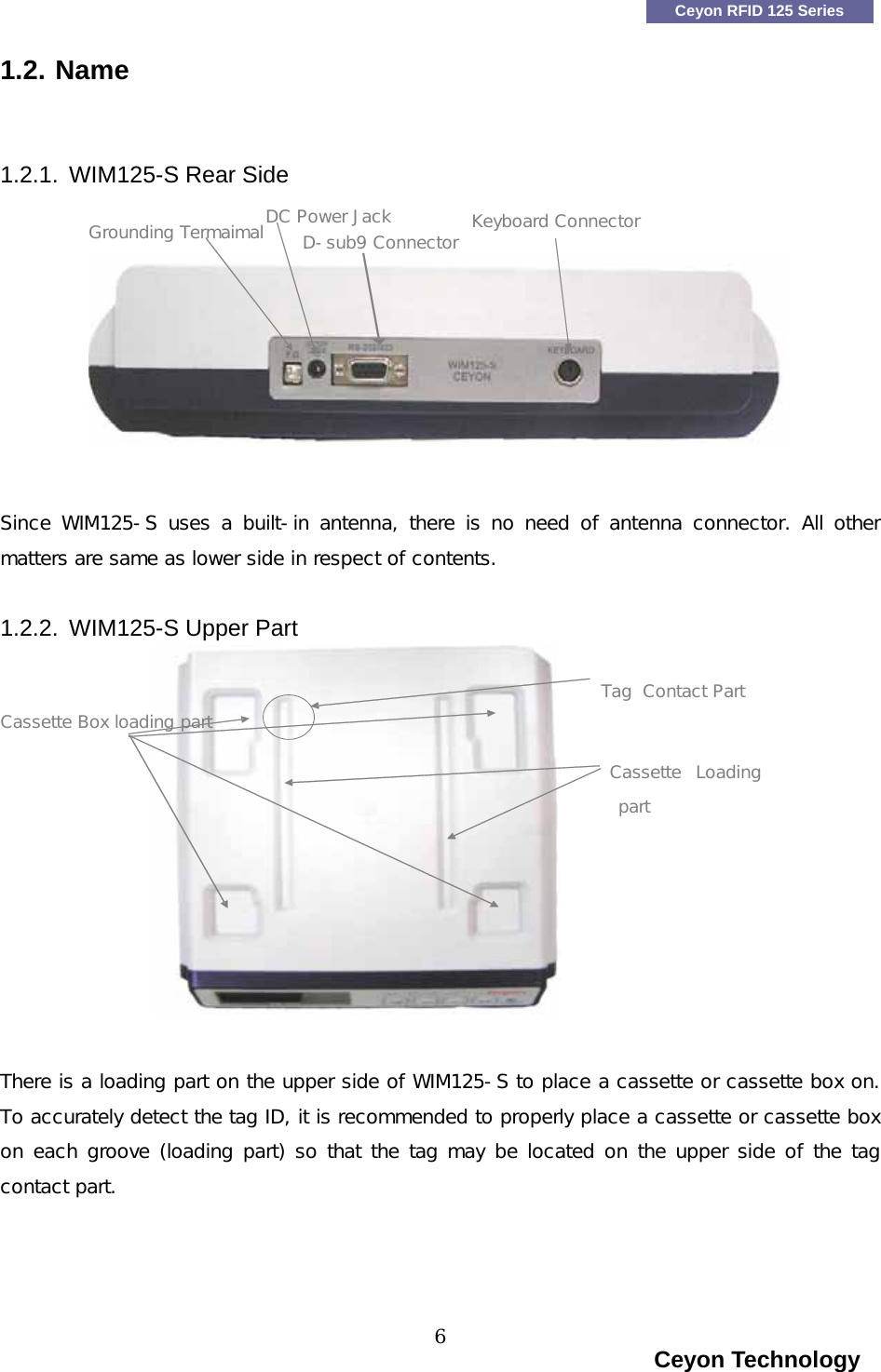
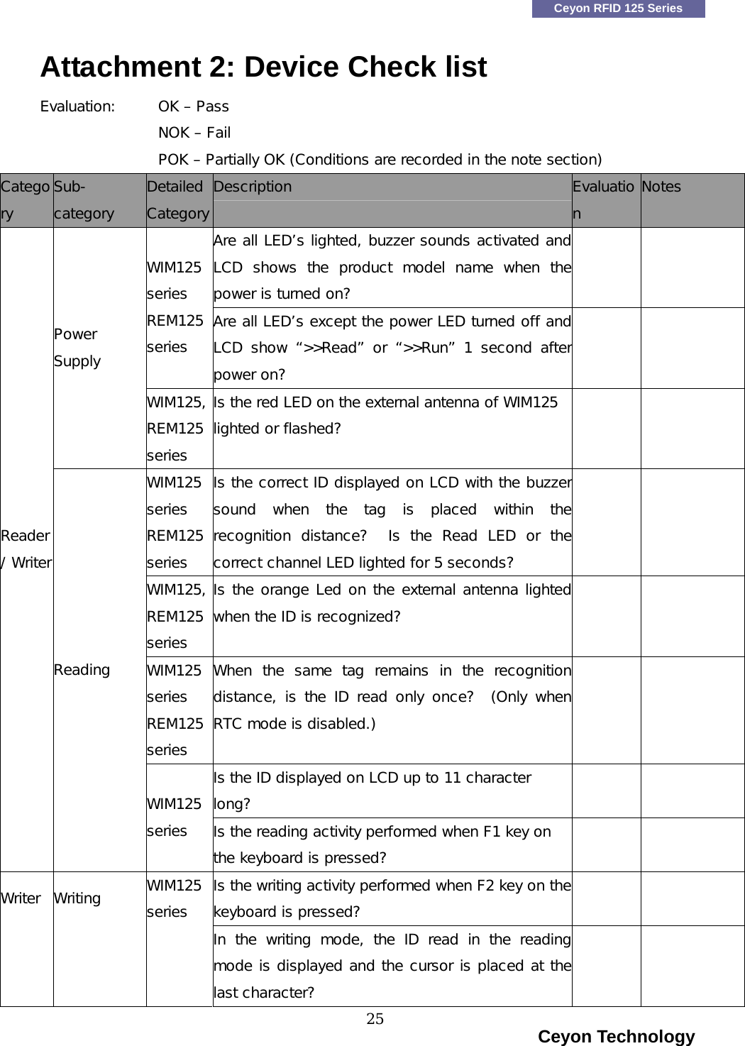
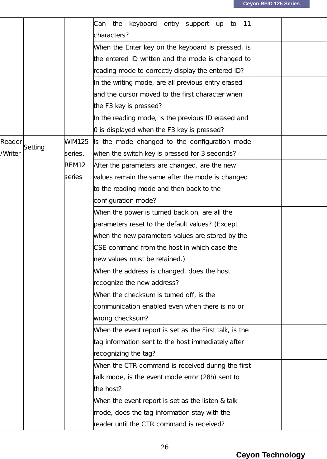
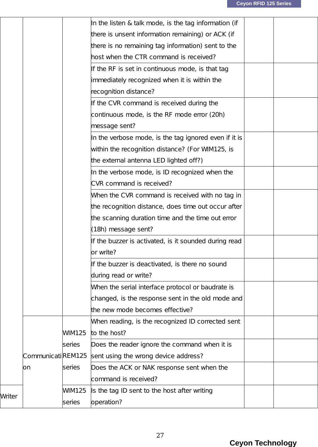
Ceyon Technology WIM125-S RFID Reader/Writer User Manual
Ceyon Technology Co., Ltd. RFID Reader/Writer
UserManual.wiki
>
Ceyon Technology
>
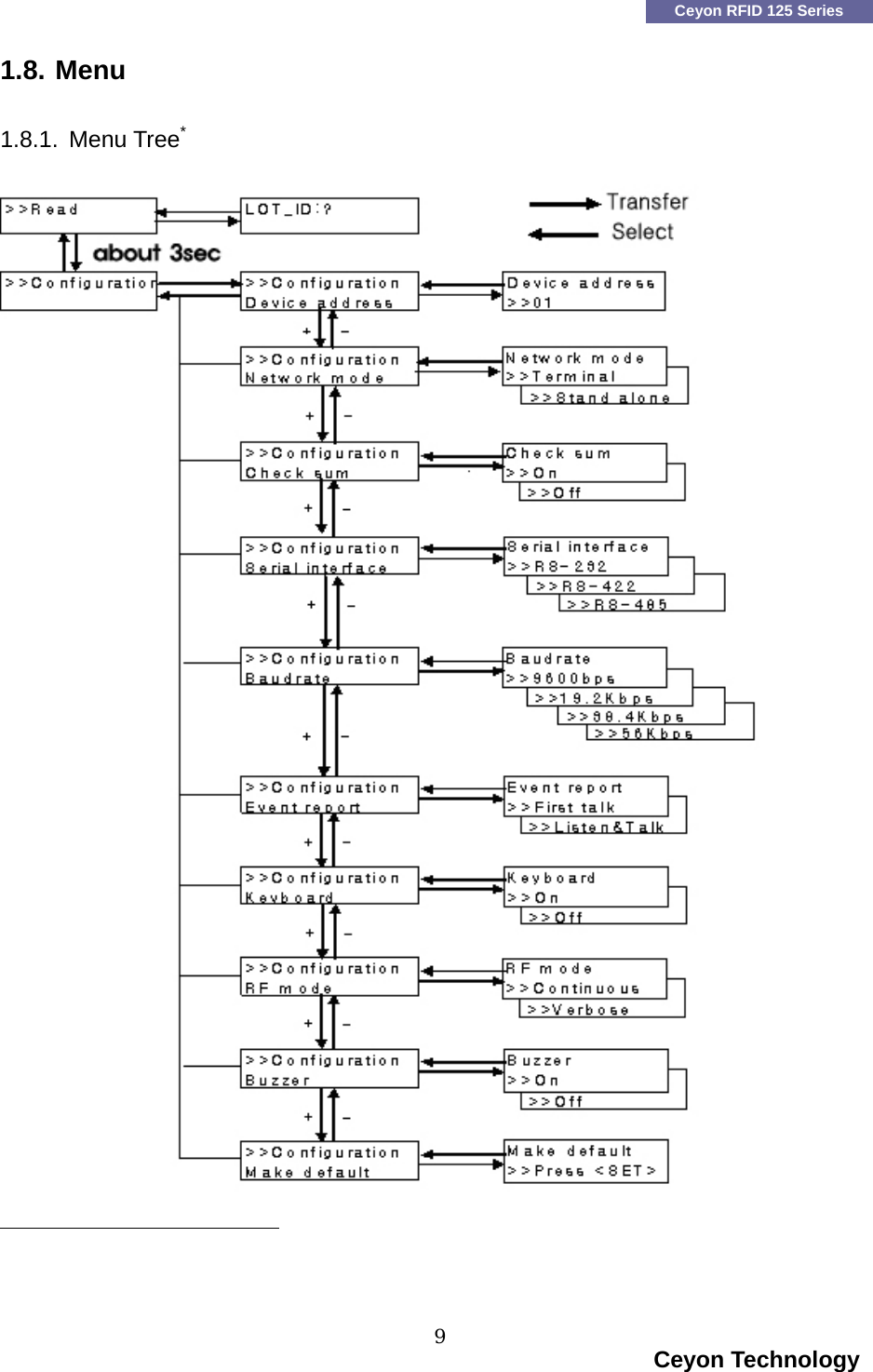
WIM125 S User Manual
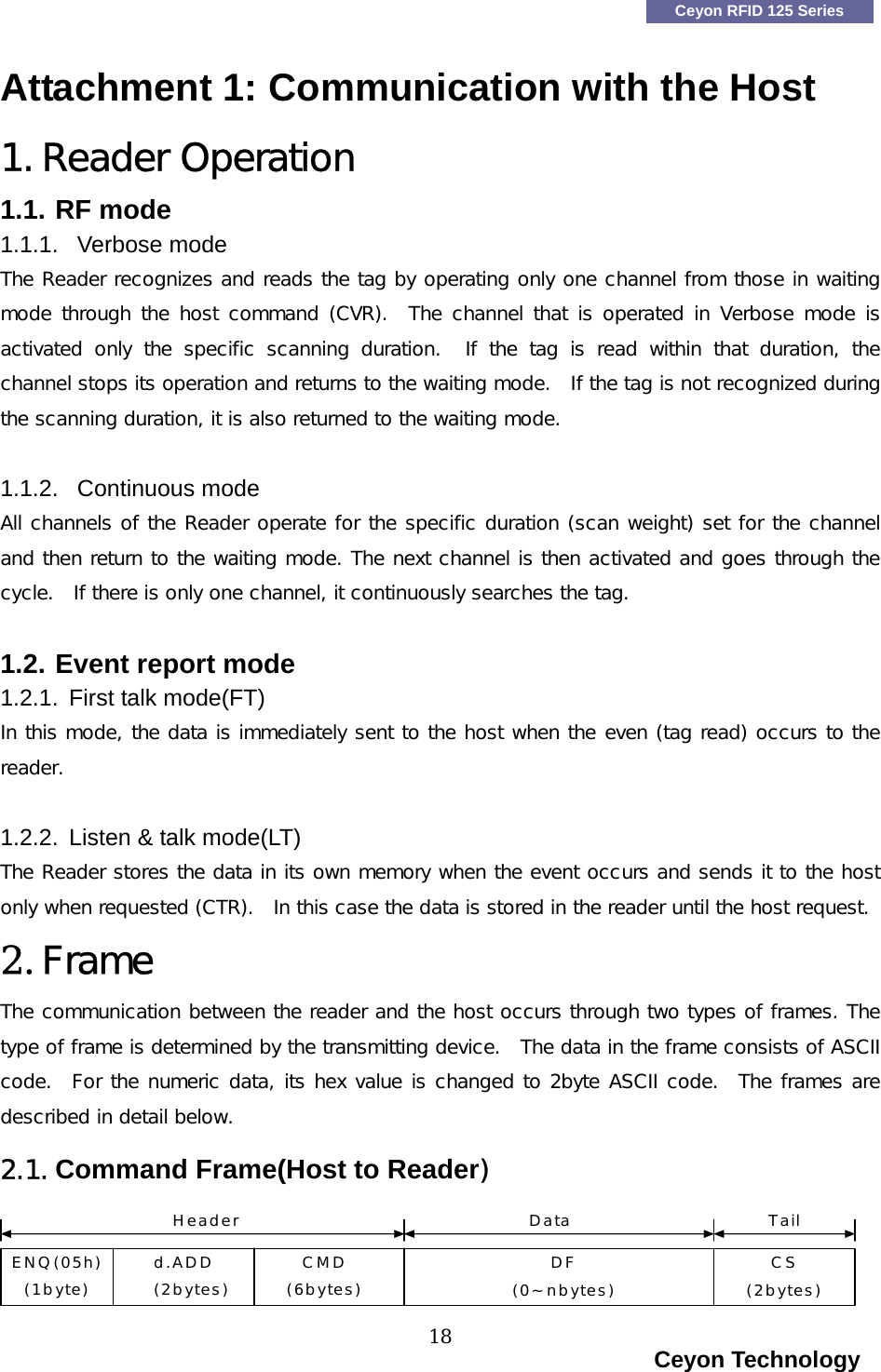
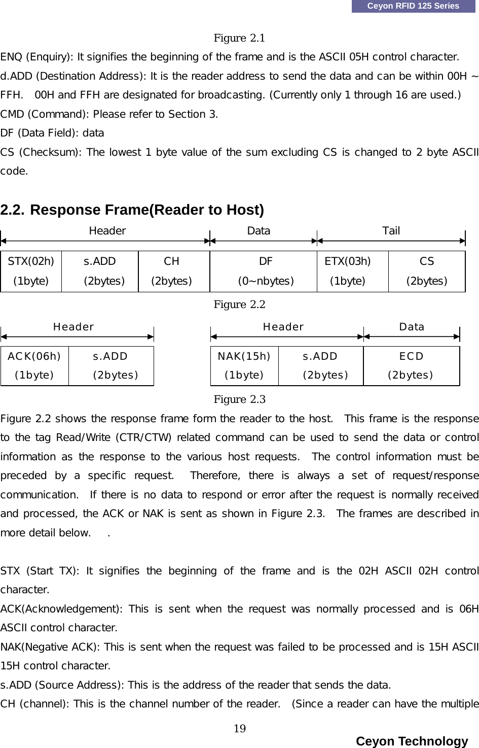
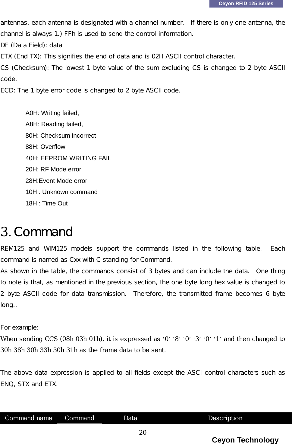
Users Manual
Navigation menu
Upload a User Manual
Namespaces
Wiki Guide
HTML
PDF
Info
Views
User Manual
Discussion / Help
Navigation