Ceyon Technology WIM125-S RFID Reader/Writer User Manual
Ceyon Technology Co., Ltd. RFID Reader/Writer
Users Manual

FCC ID : UDCWIM125-S
HYUNDAI CALIBRATION & CERTIFICATION TECHNOLOGIES CO., LTD.
SAN 136-1, AMI-RI, BUBAL-EUP, ICHEON-SI, KYOUNGKI-DO, 467-701, KOREA
TEL:+82 31 639 8517 FAX:+82 31 639 8525 www.hct.co.kr
Report No. : HCT-F06-1007 1/1
ATTACHMENT E.
- USER’S MANUAL -

CEYON
RF-ID System
MANUAL
Ceyon RFID 125 Series
RF-ID Writer
MANUAL
Ceyon Technology
2

Ceyon RFID 125 Series
Contents
RF-ID Writer MANUAL ........................................................................................................... 2
1. WIM125 Series................................................................................................................. 5
1.1. Specifications................................................................................................................. 5
1.1.1. Product specifications............................................................................................... 5
1.1.2. Environment Specifications ...................................................................................... 5
1.2. Name................................................................................................................................6
1.2.1. WIM125-S Rear Side................................................................................................ 6
1.2.2. WIM125-S Upper Part .............................................................................................. 6
1.3. Installation method ........................................................................................................ 7
1.3.1. Method to install WIM125-S ..................................................................................... 7
1.3.2. Precautions in installing WIM125 Series .................................................................. 7
1.4. Power Connection.......................................................................................................... 7
1.4.1. If power is properly input .......................................................................................... 7
1.4.2. If power is improperly input....................................................................................... 7
1.4.3. Check following points:............................................................................................. 8
1.5. Antenna Connection...................................................................................................... 8
1.6. Connection of Communication Lines .......................................................................... 8
1.7. Connection of Keyboard................................................................................................ 8
1.8. Menu................................................................................................................................9
1.8.1. Menu Tree................................................................................................................. 9
1.8.2. Read Operation (Read Mode) ................................................................................ 10
1.8.3. Write Operation(Write Mode).................................................................................. 10
1.8.4. Configuration Mode .................................................................................................11
1.9. Host Communication................................................................................................... 14
1.10. Checking Points of Unit............................................................................................... 14
1.10.1. Power Application................................................................................................... 14
1.10.2. ID Read/Write ......................................................................................................... 14
1.11. Problems and Troubleshooting .................................................................................. 15
1.11.1. Problems related with power supply....................................................................... 15
1.11.2. Problems related with network access................................................................... 15
1.11.3. Problems related with operation............................................................................. 15
Attachment........................................................................................................................... 17
Ceyon Technology
3

Ceyon RFID 125 Series
Attachment 1: Communication with the Host ................................................................... 18
1. Reader Operation........................................................................................................... 18
1.1. RF mode........................................................................................................................ 18
1.1.1. Verbose mode......................................................................................................... 18
1.1.2. Continuous mode ................................................................................................... 18
1.2. Event report mode........................................................................................................ 18
1.2.1. First talk mode(FT) ................................................................................................. 18
1.2.2. Listen & talk mode(LT)............................................................................................ 18
2. Frame.............................................................................................................................. 18
2.1. Command Frame(Host to Reader).............................................................................. 18
2.2. Response Frame(Reader to Host) .............................................................................. 19
3. Command ....................................................................................................................... 20
4. Frame Communication................................................................................................... 24
4.1. READ Command Format (08h/2nh command).......................................................... 24
4.2. WRITE Command Format (10h/18h/3nh command) ................................................. 24
Attachment 2: Device Check list ........................................................................................ 25
Ceyon Technology
4
Ceyon RFID 125 Series
1. WIM125 Series
1.1. Specifications
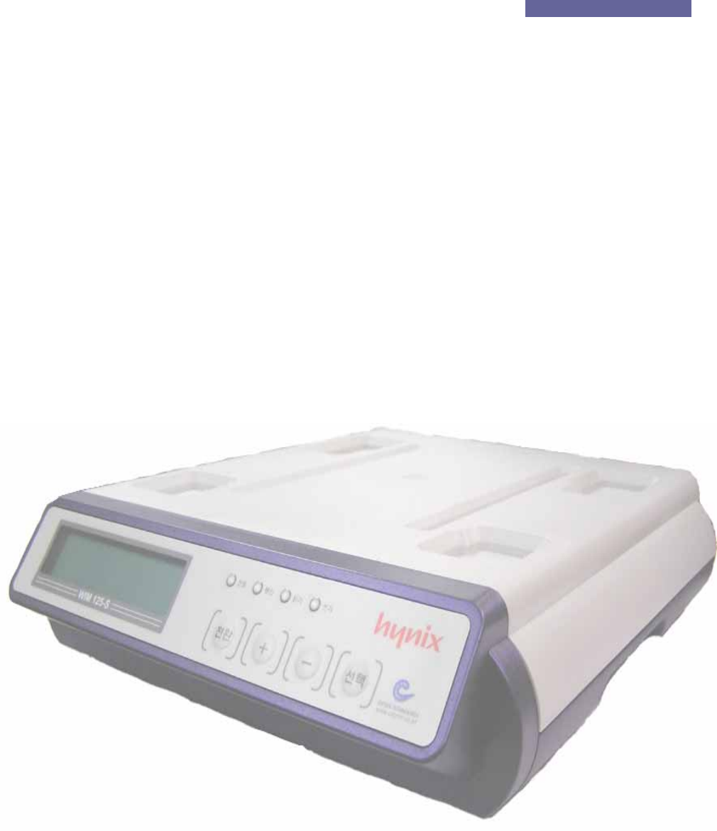
1.1.1. Product specifications
WIM125-S Parameter Description
Processor 8 bit Processor
Frequency 125 KHz
LCD type 16*2 line 32 character display
Power DC 12V / 1A
Communication RS232 , RS422, RS485
(Menu Setting)
Dimensions (W)300mm * (L)350mm * (H)75mm
Material ABS
Host Interface 1ea (RS232 , RS422, RS485)
Internal ant. 1ea
LED display POWER, COM, READ, WRITE
KEY 4 KEYS
Keyboard I/F 1ea
1.1.2. Environment Specifications
Item Specifications
Operation temperature range 0℃ to +65℃
Operation humidity range 20 % ~ 90 % (No dewing)
Operation atmospheric pressure
range
1 atmospheric pressure
Conservation temperature range 0℃ to +80℃
Conservation humidity range 20 % ~ 90 % (No dewing)
Ceyon Technology
5
Ceyon RFID 125 Series
1.2. Name
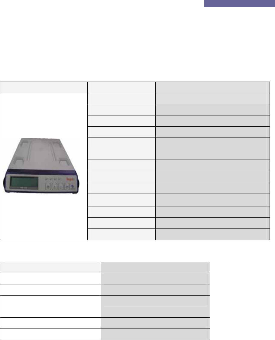
1.2.1. WIM125-S Rear Side
DC Power Jack Ke
y
board Connector
Ceyon Technology
6
Grounding T
Since WIM125-S uses a built-in antenna, there is no need of antenna connector. All other
matters are same as lower side in respect of contents.
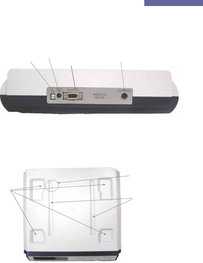
1.2.2. WIM125-S Upper Part
There is a loading part on the upper side of WIM125-S to place a cassette or cassette box on.
To accurately detect the tag ID, it is recommended to properly place a cassette or cassette box
on each groove (loading part) so that the tag may be located on the upper side of the tag
contact part.
D-sub9 Connector
ermaimal
Cassette Box loading
p
art
artContact P
Ta
g
Cassette Loadin
g
part

Ceyon RFID 125 Series
1.3. Installation method
1.3.1. Method to install WIM125-S
WIM125-S should be installed on even surface with sufficient space is obtained, and it is better
to install at appropriate height so that it is easy for worker to operate.
1.3.2. Precautions in installing WIM125 Series
① If difficult to perform drill work on the adhesion surface inevitably, install the WIM125
at a designated location by using a separate bracket.
② Install WIM125 Series at a place where it is easy for worker to operate.
③ Install WIM125 Series at a place where it is easy to supply power or connect
communication lines.
④ Adhesion surface and bracket materials should not be of metal-series (including SUS, AL)
and material to absorb wave (magnet, ferrite, etc) should be avoided. If adhesion surface
and bracket materials are of metal-series or material to absorb wave, a separate
consultation is needed in relation with installation.
⑤ Install antenna at a place possible to read out.
⑥ Installing product around equipment should be avoided where 125KHz and low frequency
occur.
.
1.4. Power Connection
Insert adaptor supplied by our corporation into a DC power jack.
1.4.1. If power is properly input
All LEDs turn on after powering on.
Boozer rings for about 1second.
If fixed time eclipses after LED model name* of WIM125 is displayed on LED, the boozer rings,
all LEDs turn off, only red Power LED turns on, converting to operation mode (read).
1.4.2. If power is improperly input
No LED turns on.
No boozer rings.
No LCD message properly plays.
Ceyon Technology
7

Ceyon RFID 125 Series
1.4.3. Check following points:
For improper operation, check power adaptor.
Check input power is about DC15V in no load condition.
Check power polarity of adapter is proper. (For adapter other than that provided by our
corporation)
1.5. Antenna Connection
Antenna terminal is composed of a 6-pin miniature DIN jack and length of antenna cables is 2M.
In some cases, a flat cable adaptor PCB provided by our corporation may be used for extension
of a flat cable. Maximum 3.5m of flat cable can be used in mixed use of 1.5m. Arbitrary cutting
or modification of cables provided by our corporation should not be used. Since reading
distance may largely differ depending on size antenna and tag, other types of antenna are
variously prepared. Consult technical staff of our corporation considering purpose and
environment to use.
1.6. Connection of Communication Lines
Communication line connection between WIM125 Series and HOST is explained.
Since detailed specification is same as REM125 Series, refer to REM125 Manua.
1.7. Connection of Keyboard
WIM125 Series enables to easily input tag ID by using a keyboard.
All general keyboards used in a computer are supported. It is possible to use only if simply
connecting them to the keyboard connector. ID input using characters, numbers and symbol
keys on the keyboard is allowed. No direction keys (→,←,↑,↓), edit keys (Insert, Delete, Home,
End, PageUp, PageDown) and several special function keys are not used. Convenient short
keys may be used if using the keyboard as follow:
‘F1’: Performs reading operation in the Read Mode.
Perform reading operation after converting from Write Mode to Read Mode.
‘F2’: Converts from Read Mode to Write Mode. In this case, if there is an ID read in the Read
Mode, the cursor is located at the last character of the ID.
‘F3’: Converts from Read Mode to Write Mode, erases all IDs of the tag. Convert to the Read
Mode after inputting ‘0’ into the tag.
Erases all characters input in the Write Mode and then moves the cursor to the original position.
Ceyon Technology
8

Ceyon RFID 125 Series
1.8.2. Read Operation (Read Mode)
“>>Read” is displayed on the LCD window.
Read mode is a mode firstly entering after applying power, and is set to Continuous (RF mode)
and First talk (Event report) in shipment out of factory. Tag ID is detected together with boozer
sound when tag approaches to the antenna and is displayed on LCD (for about 5 seconds and
ID is transmitted to the host at the same time. Maximum character numbers are 11 characters
displayed on LCD.
1.8.2.1. Method to re-detect same Tag ID
If tag falls within the recognition scope of antenna in basic mode, it performs ID detection only
once, and if the same tag continues to fall within the recognition scope of antenna, it performs
detection no longer. In this case, following methods are used when desire to detect ID of the
same tag:
Separate tag from antenna by sufficient distance (about 30cm) and then approach it to antenna
again after waiting for about 1 second.
Enable to detect ID by pressing the F1 key when the keyboard is adhered.
Read operation continues to perform when tag exists within distance of recognizing antenna if
activating RTC by using a CRTC∗(Command of Reset Tag in Continuous mode) in the host in
connection with the host.
1.8.3. Write Operation(Write Mode)
Write Mode is displayed as “LOT_ID :” on the LCD window and the cursor flickers.
This is a mode to input ID into the Tag and can be entered by using a F2 key on the keyboard.
This mode can be converted to Read Mode by pressing ‘Conversion’ key for about 3 seconds or
pressing the F1 key on the keyboard.
1.8.3.1. ID Entry
For ID, up to 1 ~ 23**characters can be entered. In this case, there should be no space
between characters. If reaching to maximum character numbers of entry, entry is done no
∗ If referring to annexed protocol, detailed descriptions for CRTC mode is provided. In addition to
them, refer to protocol for both RF mode and Event report mode related with reading.
** Only LOT_ID up to 11 characters can be entered when entering with the keyboard, and in order
to all 23 characters, CTW commands should be used in the HOST. For further details, refer to
annexed protocol.
Ceyon Technology
10

Ceyon RFID 125 Series
longer and boozer sound informs status that it is impossible to enter whenever pressing the key.
If pressing ‘Enter’ key on the keyboard in order to complete entry, write operation is performed.
Standby status of entry remains in the Write Mode. If Write Mode is completed, boozer sound
rings triple time shortly and the Write Mode is converted to Read Mode.
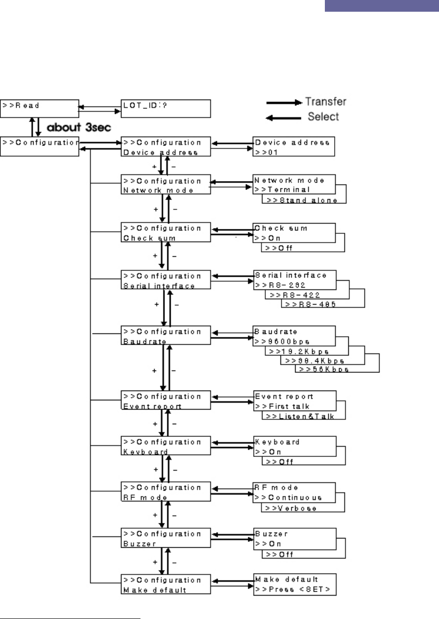
1.8.4. Configuration Mode *
This mode is displayed as “>>Configuration” on the LCD window.
This is mode to change various settings of the unit and can be entered by pressing the
‘Conversion’ key for more than 3 seconds. For detailed setting items, refer to the Menu Tree.
1.8.4.1. Boozer sound
Boozer sound rings whenever changing each of settings and respective meaning is as follow:
Short Beep triple time: Means completed setting or OK.
Short Beep once: Means that setting values change.
1.8.4.2. Key operation
Respective key performs following operation when changing settings by using a key:
FUNC (conversion): Moves to previous menu or upper menu after canceling without selecting
setting values.
SET (Select): Moves upper menu or lower menu after selecting setting values.
INC (+)/DEC(-): Change items.
Automatically return to Read Mode if not pressing the key for 10 seconds after the final key
entry.
1.8.4.3. Addressing
Always designate and use address of the unit if executing multi communication except for
point to point. Up to No 1 ~ 16 can be entered. In shipment, address is set to No. ‘1’.
Since communication with the host is not done in changing unit number, do not change the unit
number unless there is sufficient understanding about use of the unit.
Ceyon Technology
11

Ceyon RFID 125 Series
Sequence Key Entry LCD Message Remarks
1 FUNC
(conversion)
>>Configuration Enter into Configuration mode with a
long beep sound if pressing FUNC
(conversion) key for 3 seconds.
2 SET (selection) >>Configuration
Device address
Setting items
3 SET (selection) Device address
>>01
Displays current setting values
4 INC(+)/DEC(-) Address
increase/decrease
Setting scope: 1 ~ 16
5 SET (selection) >>Configuration
Device address
Addressing is done with a short beep
sound triple times and moves to the
upper mode.
6 FUNC
(conversion)
>>Configuration Moves to upper mode.
7 FUNC >>Read Moves to Read Mode.
1.8.4.4. Network mode
This is mode to set network connection status and the user can control this mode at the host by
connecting (terminal mode) it to the host or directly operate (stand alone) the unit.
Sequence Key Entry LCD Message Remarks
1 FUNC
(conversion)
>>Configuration Enter into Configuration mode with
a long beep sound if pressing
FUNC (conversion) key for 3
seconds.
2 SET (selection) >>Configuration
Device address
Setting item
① INC(+)/DEC(-) >>Configuration
Network mode
Moves to setting item.
3 SET (selection) Network mode
>>Terminal
Displays current setting values.
4 INC(+)/DEC(-) Changes setting
values
5 SET (selection) >>Configuration Addressing is done with a short
Ceyon Technology
12

Ceyon RFID 125 Series
Network mode beep sound triple times and moves
to the upper mode.
6 FUNC
(conversion)
>>Configuration Moves to upper mode.
7 FUNC >>Read Moves to Read Mode.
1.8.4.5. Checksum setting
User can insert or delete checksum information to detect fault operartion when translating
detected tag ID to the host. Menu setting is same as network mode setting.
You can add or remove 2 bytes of checksum information to detect error of data when
transmitting ID detected from the host. As for method to setup menu, you can set it in the same
manner as network mode setting method.
1.8.4.6. Serial interface setting
This is item to set physical communication covenants connected to the host, and supports RS-
232, RS-422 and RS-485.
1.8.4.7. Baud rate setting
You can set communication speed when communicating to the host, and this mode supports
9600bps, 19.2Kbps, 38.4Kbps and 56Kbps.
.
1.8.4.8. Event report setting
This is item to setup method to transmit tag ID read in the Read Mode to the host and for further
details, refer to annexed protocol.
1.8.4.9. Keyboard setting
You can set to on when using the keyboard, and if there is no keyboard, set to Off.
There is no need of changing this keyboard setting when using it as terminal mode since it is
not affected by On/Off setting.
1.8.4.10. RF mode setting
This mode is to set RF operation for Read Mode and for further details that refer to annexed
protocol.
1.8.4.11. Buzzer setting
This is mode used when turning on or off boozer sound generated in detection Tag ID or
Ceyon Technology
13

Ceyon RFID 125 Series
performance of ID writing. In this case, key operation boozer sound also rings in the Off status.
1.8.4.12. Factory setting
This is mode used when restoring to setting value in shipment of factory. Setting is changed to
the first setting value of each menu.
1.9. Host Communication
WIM125 Series communicates with the host by using same protocol as REM125 Series and you
can perform transmission/receipt of ID, setting, etc of the unit at the host. For further details,
refer to annexed protocol.
1.10. Checking Points of Unit
To check normal operation of the unit, refer to following items:
1.10.1. Power Application
① Do All LEDs turn on and boozer sound rings when power is applied, and is model name
of product displayed on LCD?
② Do all LEDs except for power LED turn off after about 1 second from power application
and is “>>Read” displayed on the LCD?
③ For WIM125, does the red LED turn on in the antenna installed outside?
1.10.2. ID Read/Write
① Is a proper ID on the LCD together with boozer sound when placing a tag within
recognition distance? Does the Read LED turn on and continue for about 5 seconds
(For WIM125, does the yellow LED turn on the antenna installed outside?
② When continuously placing same tag within recognition distance of the antenna, does it
detect ID no longer after reading it once? (However, RTC mode must be disabled)
③ Is up to 11 characters of ID displayed on LCD?
④ Is read operation performed when pressing the F1 key of the keyboard?
⑤ Is it converted to Write Mode when pressing F2 of the keyboard?
⑥ For Write Mode, is ID read in Read Mode displayed? Does the cursor locate at the last
character?
⑦ Is up to 11 characters on the keyboard?
⑧ Is entered ID when pressing the Enter key of the keyboard? Is entered ID properly
displayed after converting it to Read Mode?
⑨ Are all entered characters erased when pressing the F3 key of the keyboard in the Write
Ceyon Technology
14

Ceyon RFID 125 Series
Mode? Does the cursor locate at the first?
⑩ Are all previous ID erased when pressing the F3 key of the keyboard in the Read Mode?
Is ‘0’ entered?
Refer to the annexed unit check list for detailed checking points that operate needs other than
above checking points.
1.11. Problems and Troubleshooting
Problems to likely occur by type and are suggested and methods to solve them are introduced.
1.11.1. Problems related with power supply
Q1. No LED turns on when connecting power connector.
A1. Check following points if such problems occur:
Check output of adaptor, a power supply unit comes out (DC12V / 1A)
Remove a DC power jack and then connect and restart it after about 10 seconds.
1.11.2. Problems related with network access
Q1. No host and WIM125 are connected.
A1. Check following points if such problems occur:
Check connection status of various cables connecting host and unit, etc once again.
Also check exclusive cables are connected.
Check operation status both host and machine.
Q2 No WIM125 and antenna are connected.
A2. Check following points if such problems occur:
Check connection status of various cables connecting both WIM125 and antenna once
again.
Also check exclusive cables are connected.
Check operation status both 2WIM125 and antenna.
1.11.3. Problems related with operation
Q1. No operation is done.
A1. Check communication lines of the unit is properly connected.
Check power is properly supplied.
Ceyon Technology
15

Ceyon RFID 125 Series
Q2. No operation even after communication and power lines are entirely connected.
A2. Check exclusive cables provided are used.
Check addressing is properly set.
Supply power again.
Check they are in regulated command format.
Q3. Error occurs even though tag is located within valid distance for reading.
A3. Supply power again.
Check operation mode.
If they are tags that error occurred during write operation, perform proper writing operation
once again.
Q4. Writing fail or Verify fail occurs.
A4. Supply power again.
Check proper reading is performed.
Check that distance between tag and antenna is appropriate.
If problems are not solved in above methods, consult Ceyon Technology Co., Ltd. (+82-31-
267-1163) after immediately removing cables from the power input port.
Ceyon Technology
16

Ceyon RFID 125 Series
Attachment
Ceyon Technology
17

Ceyon RFID 125 Series
Attachment 1: Communication with the Host
1. Reader Operation
1.1. RF mode
1.1.1. Verbose mode
The Reader recognizes and reads the tag by operating only one channel from those in waiting
mode through the host command (CVR). The channel that is operated in Verbose mode is
activated only the specific scanning duration. If the tag is read within that duration, the
channel stops its operation and returns to the waiting mode. If the tag is not recognized during
the scanning duration, it is also returned to the waiting mode.
1.1.2. Continuous mode
All channels of the Reader operate for the specific duration (scan weight) set for the channel
and then return to the waiting mode. The next channel is then activated and goes through the
cycle. If there is only one channel, it continuously searches the tag.
1.2. Event report mode
1.2.1. First talk mode(FT)
In this mode, the data is immediately sent to the host when the even (tag read) occurs to the
reader.
1.2.2. Listen & talk mode(LT)
The Reader stores the data in its own memory when the event occurs and sends it to the host
only when requested (CTR). In this case the data is stored in the reader until the host request.
2. Frame
The communication between the reader and the host occurs through two types of frames. The
type of frame is determined by the transmitting device. The data in the frame consists of ASCII
code. For the numeric data, its hex value is changed to 2byte ASCII code. The frames are
described in detail below.
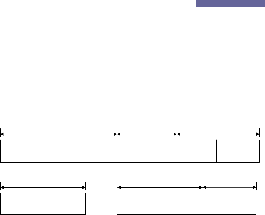
2.1. Command Frame(Host to Reader)
ENQ(05h)
(1byte)
d.ADD
(2bytes)
CMD
(6bytes)
DF
(0~nbytes)
CS
(2bytes)
Header Data Tail
Ceyon Technology
18
Ceyon RFID 125 Series
Figure 2.1
ENQ (Enquiry): It signifies the beginning of the frame and is the ASCII 05H control character.
d.ADD (Destination Address): It is the reader address to send the data and can be within 00H ~
FFH. 00H and FFH are designated for broadcasting. (Currently only 1 through 16 are used.)
CMD (Command): Please refer to Section 3.
DF (Data Field): data
CS (Checksum): The lowest 1 byte value of the sum excluding CS is changed to 2 byte ASCII
code.
2.2. Response Frame(Reader to Host)
STX(02h)
(1byte)
s.ADD
(2bytes)
ETX(03h)
(1byte)
DF
(0~nbytes)
CS
(2bytes)
Header Data Tail
CH
(2bytes)
Figure 2.2
ACK(06h)
(1byte)
s.ADD
(2bytes)
Header
NAK(15h)
(1byte)
s.ADD
(2bytes)
Header
ECD
(2bytes)
Data
Figure 2.3
Figure 2.2 shows the response frame form the reader to the host. This frame is the response
to the tag Read/Write (CTR/CTW) related command can be used to send the data or control
information as the response to the various host requests. The control information must be
preceded by a specific request. Therefore, there is always a set of request/response
communication. If there is no data to respond or error after the request is normally received
and processed, the ACK or NAK is sent as shown in Figure 2.3. The frames are described in
more detail below. .
STX (Start TX): It signifies the beginning of the frame and is the 02H ASCII 02H control
character.
ACK(Acknowledgement): This is sent when the request was normally processed and is 06H
ASCII control character.
NAK(Negative ACK): This is sent when the request was failed to be processed and is 15H ASCII
15H control character.
s.ADD (Source Address): This is the address of the reader that sends the data.
CH (channel): This is the channel number of the reader. (Since a reader can have the multiple
Ceyon Technology
19

Ceyon RFID 125 Series
antennas, each antenna is designated with a channel number. If there is only one antenna, the
channel is always 1.) FFh is used to send the control information.
DF (Data Field): data
ETX (End TX): This signifies the end of data and is 02H ASCII control character.
CS (Checksum): The lowest 1 byte value of the sum excluding CS is changed to 2 byte ASCII
code.
ECD: The 1 byte error code is changed to 2 byte ASCII code.
A0H: Writing failed,
A8H: Reading failed,
80H: Checksum incorrect
88H: Overflow
40H: EEPROM WRITING FAIL
20H: RF Mode error
28H:Event Mode error
10H : Unknown command
18H : Time Out
3. Command
REM125 and WIM125 models support the commands listed in the following table. Each
command is named as Cxx with C standing for Command.
As shown in the table, the commands consist of 3 bytes and can include the data. One thing
to note is that, as mentioned in the previous section, the one byte long hex value is changed to
2 byte ASCII code for data transmission. Therefore, the transmitted frame becomes 6 byte
long..
For example:
When sending CCS (08h 03h 01h), it is expressed as ‘0’ ‘8’ ‘0’ ‘3’ ‘0’ ‘1’ and then changed to
30h 38h 30h 33h 30h 31h as the frame data to be sent.
The above data expression is applied to all fields except the ASCI control characters such as
ENQ, STX and ETX.
Command name Command Data Description
Ceyon Technology
20

Ceyon RFID 125 Series
code
CCS
(Ch. Status)
08h 03h 01h None This CCE related command checks the
enabled ch. The data in the response is 1
byte in the same format as CCE data byte
with the bit position of the enabled ch. set. .
CRA
(Read Address)
08h 17h 01h None It reads the 1 byte address of the reader.
CMI
(Manufacturer
Info.)
08h 20h 08h None It reads the 8 byte manufacturer
information.
CPI
(Protocol ver.
Info.)
08h 28h 08h None It reads the 8 byte protocol version
information.
CFI
(F/W ver. Info)
08h 30h 08h None It reads the 8 byte firmware version
information.
CVM
(Verbose Mode)
10h 0Bh 01h 00h – Continuous
01h- Verbose In the verbose mode, only the channel that
was activated by the CVR command scans
the tag and returns to the waiting mode
after tag reading.
In the continuous mode, the channels
activated by CCE command take the turn to
scan the tag.
CFT
(First Talk)
10h 0Bh 02h 00h –Listen &
talk In the LT mode, the tag information is
stored into the reader memory until the
host requests it through CTR command. In
the FT mode the tag information is
immediately sent to the host.
01h – First talk
CRTC
(Reset Tag in
Continuous mode)
10h 0Bh 03h 00h – Disable
01h - Enable This command is valid only for the
continuous mode.
If RTC is enabled, the same tag data is
continuously sent as long as the tag
remains within the recognition distance. If
it is disabled, the same tag information is
sent only at first.
CVTL
(Verbose Time
Limit)
10h 0Bh 06h 01h –Enable
Time out In the verbose mode, the tag is scanned
when the CVR command is received for the
duration set in the CTT mode. If it is
timed out without tag recognition, time out
error is sent.
CBS
(Buzzer Set)
10h 0Bh 07h 00h – Buzzer off
01h – Buzzer on It activates or deactivates the buzzer
operations for successful tag read or write.
CDC 10h 18h 03h 01h It checks the reader condition according to
Ceyon Technology
21

Ceyon RFID 125 Series
Ceyon Technology
22
(Device Check) ACK, NAK or no response.
CSE
(Save setting to
Eeprom)
10h 18h 05h 01h The reader parameter settings are stored
in EEPROM so that the values remain the
same even when the power is turned off.
Without this command, the parameters are
reset to default values when the power is
turned on.
CGB
(Good Beep)
10h 19h 05h 01h A good beep is activated.
CEB
(Error Beep)
10h 19h 06h 01h An error beep is activated.
CLB
(Long Beep)
10h 19h 07h 01h A long beep is activated.
CCE
(Ch. Enable)
18h 03h 01h 01h(0000 0001)
–
ch1
02h(0000 0010)
–
ch2
04h(0000 0100)
–
ch3
08h(0000 1000)
–
ch4
10h(0001 0000)
–
ch5
Each channel is enabled or disabled.
CSI
(Serial Interface)
18h 0Ch 01h 상위 4bits: type
0 – RS422
1 – RS485
2 – RS232
하위 4bits: BPS
6 – 9600bps
7 – 19.2kbps
8 – 38.4kbps
9 – 56kbps
Set serial interface and transmition speed
between Host and reader.
Changed information will be applied after
sending Ack response .
Ex) RS422, 9600bps
Data – 06h
CTT
(Tag Time)
18h 1Dh 01h 00h – 0초
01h (0.5 second)
~ 0Ah(5 seconds)
It sets the channel scanning duration when
activated by CVR command.
* Increment of 0.5
seconds.
*It is recommended that at least 3 second
duration is set before timeout for data
stability.
CSA
(Set Address)
18h 17h 01h The device
address between
1 and 16
(01h~10h)
It sets the 1 byte device address. The
change is completed after the Ack response
is sent.
CVR
(Verbose ch.
Rd)
18h 19h 01h Channel 1 ~ 5
-00h deactivates
all channels.
It sets the channel to activate for the
verbose mode. The channel must have
been enabled by the CCE command, and

Ceyon RFID 125 Series
Read) only one channel can be activated at a time.
Once the reader receives this command, it
responds with the Ack and then scans the
tag for the scanning duration before
sending the tag information to the host in
response to the CTR command depending
upon FT or LT mode. If the tag is not
recognized within the scanning duration,
the time out error response is sent to the
host, and the channel is turned into the
waiting mode.
CTRn
(n ch Tag data
Read)
2nh 47h 17h None
The tag of the specific channel is read.
This command is valid for only Listen and
Talk mode. The valid range of n is 0 ~ 8.
When n = 0(CTR0, 20h), all channels read
the tag data.
* In case of CTR0, data of all channels
recognizing the tag is sent through one
frame as shown in Figure 3.1
CTWn
(n ch Tag data
Write)
3nh 47h 17h Tag data The valid range of N is 1~8.
As shown in the table, the command that starts with 08h is used to read the specific control
data from the reader. In that case no data field is used. The command that starts with 2nh is
used to read the tag data. In that case the third byte is the length of the tag data and is the
same as the data length of the frame. The command that starts with 10h is used to turn On/Off
the reader parameters. 1 means on and 0 means off. The command that starts with 18h is
used to send the specific data to the reader or tag. The last byte signifies the data length.
The 3nh command is used to write the data to the tag. The tag data length is same as the third
byte of the command. For the data field, the 1 byte hex value is changed to 2 byte ASCII code
like other fields before transmission/reception. In other words, the data length of the actual
frame is twice that of the number of bytes expressed in the last byte of 08h/18h/2n/3n
commands.
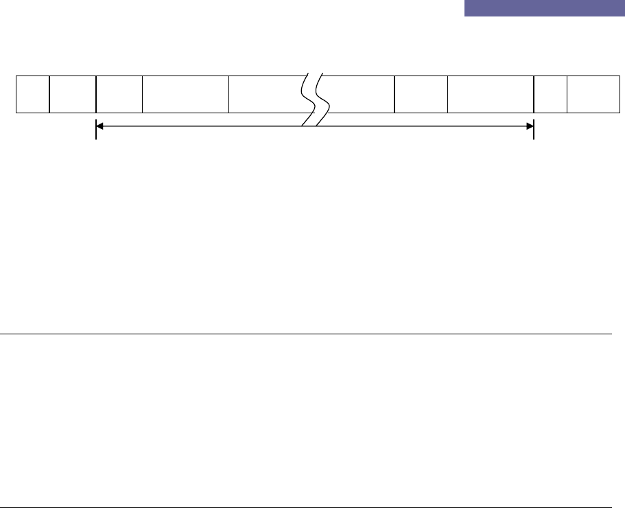
Figure 3.1 shows the response frame of CTR0 command. It is used to send all valid channel
tag data. The channel data format in the frame is same as 2 byte channel information data
Ceyon Technology
23
Ceyon RFID 125 Series
field (DF). The length of DF is same as the last byte of the CTR command.
CH Data
STX s.ADD ETXDF CSCH CH DF
Figure 3.1
4. Frame Communication
The following shows the response of the reader for each command.
4.1. READ Command Format (08h/2nh command)
Host Reader
ENQ d.ADD CMD DF CS ---------Æ
Process successful Å--------- STX s.ADD ch DF ETX CS
Tag data가 없을 때(2nh) Å--------- ACK s.ADD
Process failed Å--------- NAK s.ADD ECD
4.2. WRITE Command Format (10h/18h/3nh command)
Host Reader
ENQ d.ADD CMD DF CS ---------Æ
Process successful Å--------- ACK s.ADD
Process failed Å--------- NAK s.ADD ECD
Ceyon Technology
24

Ceyon RFID 125 Series
Attachment 2: Device Check list
Evaluation: OK – Pass
NOK – Fail
POK – Partially OK (Conditions are recorded in the note section)
Catego
ry
Sub-
category
Detailed
Category
Description Evaluatio
n
Notes
Are all LED’s lighted, buzzer sounds activated and
LCD shows the product model name when the
power is turned on?
WIM125
series
REM125
series
Are all LED’s except the power LED turned off and
LCD show “>>Read” or “>>Run” 1 second after
power on?
Power
Supply
WIM125,
REM125
series
Is the red LED on the external antenna of WIM125
lighted or flashed?
WIM125
series
REM125
series
Is the correct ID displayed on LCD with the buzzer
sound when the tag is placed within the
recognition distance? Is the Read LED or the
correct channel LED lighted for 5 seconds?
WIM125,
REM125
series
Is the orange Led on the external antenna lighted
when the ID is recognized?
WIM125
series
REM125
series
When the same tag remains in the recognition
distance, is the ID read only once? (Only when
RTC mode is disabled.)
Is the ID displayed on LCD up to 11 character
long?
Reader
/ Writer
Reading
WIM125
series Is the reading activity performed when F1 key on
the keyboard is pressed?
Is the writing activity performed when F2 key on the
keyboard is pressed?
Writer Writing WIM125
series
In the writing mode, the ID read in the reading
mode is displayed and the cursor is placed at the
last character?
Ceyon Technology
25

Ceyon RFID 125 Series
Can the keyboard entry support up to 11
characters?
When the Enter key on the keyboard is pressed, is
the entered ID written and the mode is changed to
reading mode to correctly display the entered ID?
In the writing mode, are all previous entry erased
and the cursor moved to the first character when
the F3 key is pressed?
In the reading mode, is the previous ID erased and
0 is displayed when the F3 key is pressed?
Is the mode changed to the configuration mode
when the switch key is pressed for 3 seconds?
After the parameters are changed, are the new
values remain the same after the mode is changed
to the reading mode and then back to the
configuration mode?
When the power is turned back on, are all the
parameters reset to the default values? (Except
when the new parameters values are stored by the
CSE command from the host in which case the
new values must be retained.)
When the address is changed, does the host
recognize the new address?
When the checksum is turned off, is the
communication enabled even when there is no or
wrong checksum?
When the event report is set as the First talk, is the
tag information sent to the host immediately after
recognizing the tag?
When the CTR command is received during the first
talk mode, is the event mode error (28h) sent to
the host?
Reader
/Writer Setting WIM125
series,
REM12
series
When the event report is set as the listen & talk
mode, does the tag information stay with the
reader until the CTR command is received?
Ceyon Technology
26

Ceyon RFID 125 Series
In the listen & talk mode, is the tag information (if
there is unsent information remaining) or ACK (if
there is no remaining tag information) sent to the
host when the CTR command is received?
If the RF is set in continuous mode, is that tag
immediately recognized when it is within the
recognition distance?
If the CVR command is received during the
continuous mode, is the RF mode error (20h)
message sent?
In the verbose mode, is the tag ignored even if it is
within the recognition distance? (For WIM125, is
the external antenna LED lighted off?)
In the verbose mode, is ID recognized when the
CVR command is received?
When the CVR command is received with no tag in
the recognition distance, does time out occur after
the scanning duration time and the time out error
(18h) message sent?
If the buzzer is activated, is it sounded during read
or write?
If the buzzer is deactivated, is there no sound
during read or write?
When the serial interface protocol or baudrate is
changed, is the response sent in the old mode and
the new mode becomes effective?
When reading, is the recognized ID corrected sent
to the host?
Does the reader ignore the command when it is
sent using the wrong device address?
WIM125
series
REM125
series Does the ACK or NAK response sent when the
command is received?
Writer
Communicati
on
WIM125
series
Is the tag ID sent to the host after writing
operation?
Ceyon Technology
27