Chamberlain Group The 1615 Superregenerative Receiver User Manual RAD LM DOM 535LM 535 2LM

Chamberlain Group Inc, The Superregenerative Receiver RAD LM DOM 535LM 535 2LM

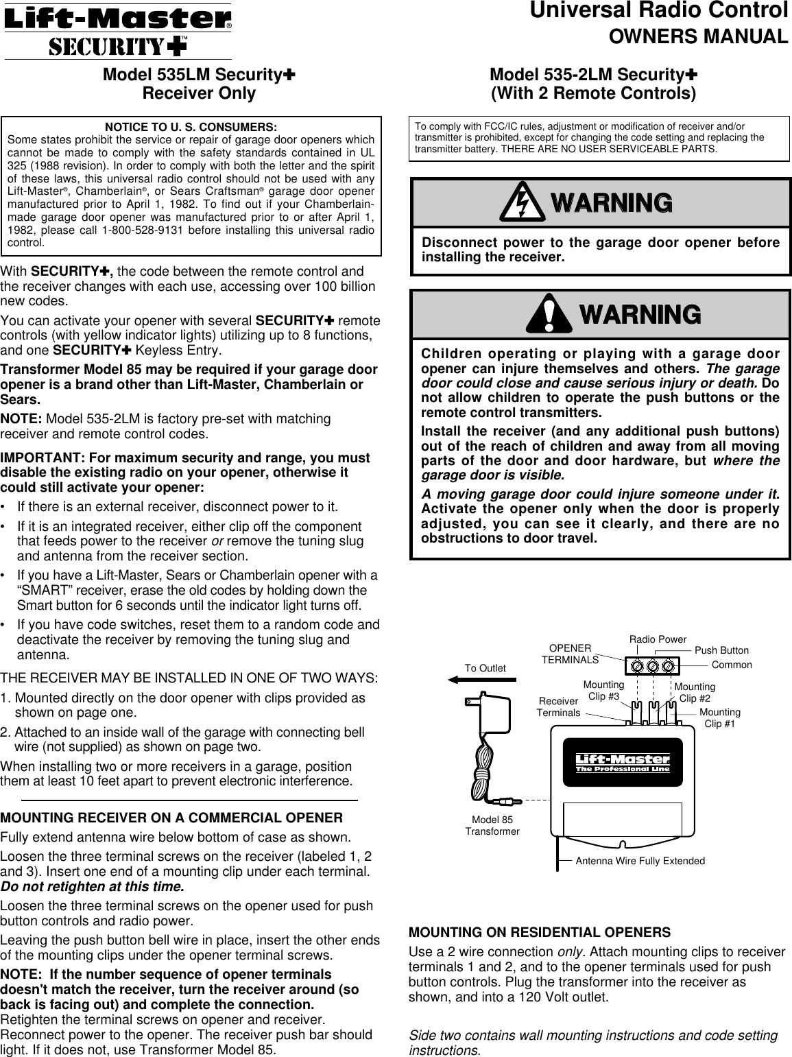
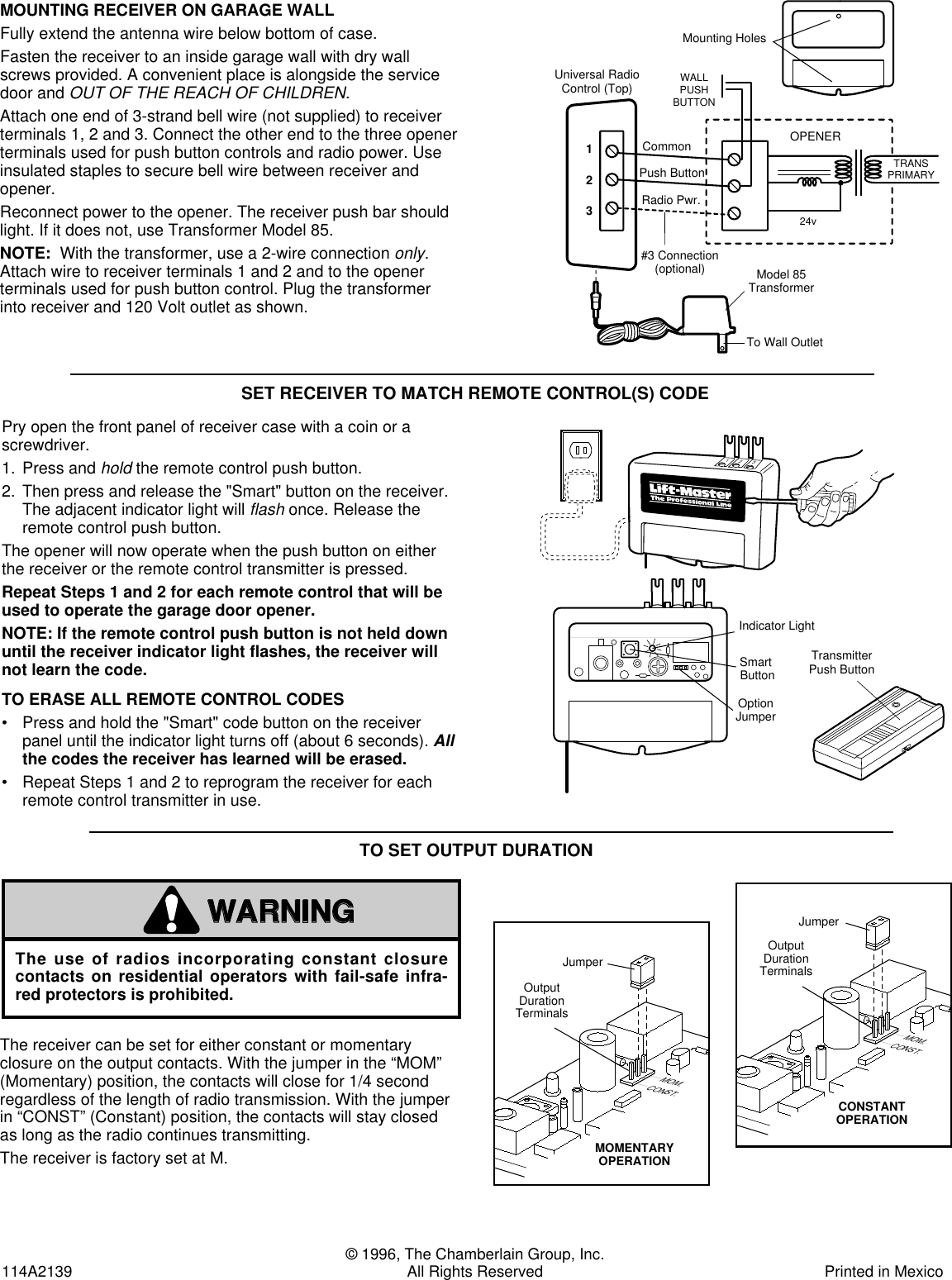
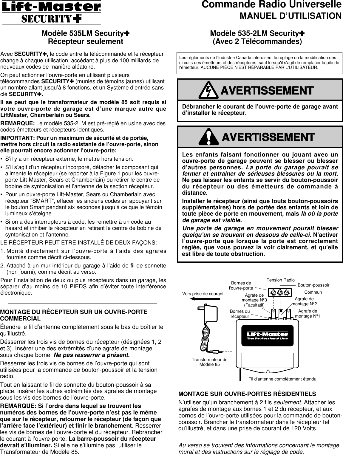
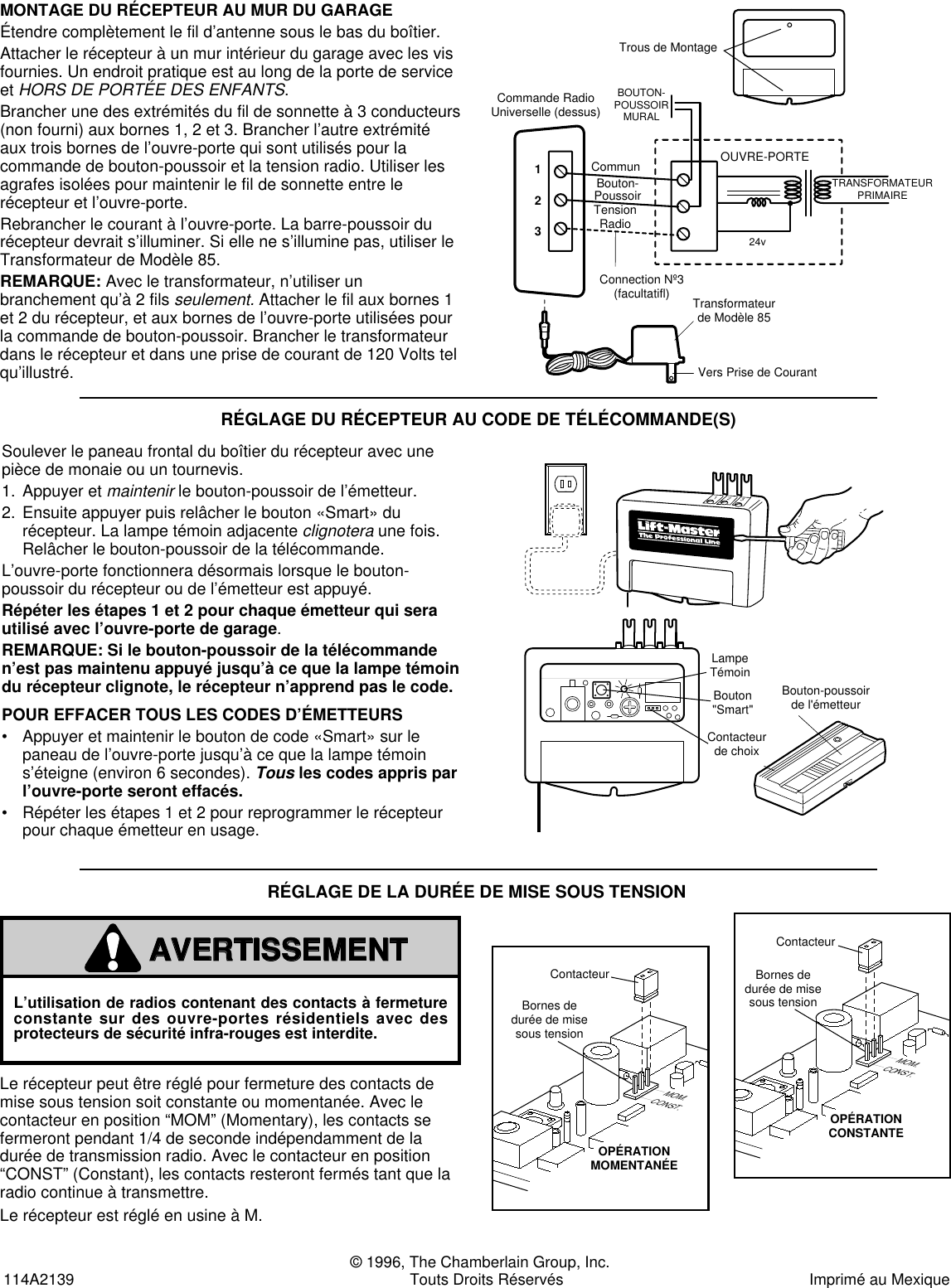
Users Manual for Model 535 315LM Superregenerative Receiver

Universal Radio ControlOWNERS MANUALWith SECURITY ✚, the code between the remote control andthe receiver changes with each use, accessing over 100 billionnew codes.You can activate your opener with several SECURITY✚remotecontrols (with yellow indicator lights) utilizing up to 8 functions,and one SECURITY✚Keyless Entry.Transformer Model 85 may be required if your garage dooropener is a brand other than Lift-Master, Chamberlain orSears.NOTE: Model 535-2LM is factory pre-set with matchingreceiver and remote control codes.IMPORTANT: For maximum security and range, you mustdisable the existing radio on your opener, otherwise itcould still activate your opener:• If there is an external receiver, disconnect power to it.• If it is an integrated receiver, either clip off the componentthat feeds power to the receiver or remove the tuning slugand antenna from the receiver section.•If you have a Lift-Master, Sears or Chamberlain opener with a“SMART” receiver, erase the old codes by holding down theSmart button for 6 seconds until the indicator light turns off.• If you have code switches, reset them to a random code anddeactivate the receiver by removing the tuning slug andantenna.THE RECEIVER MAY BE INSTALLED IN ONE OF TWO WAYS:1. Mounted directly on the door opener with clips provided asshown on page one.2. Attached to an inside wall of the garage with connecting bellwire (not supplied) as shown on page two.When installing two or more receivers in a garage, positionthem at least 10 feet apart to prevent electronic interference.MOUNTING RECEIVER ON A COMMERCIAL OPENERFully extend antenna wire below bottom of case as shown.Loosen the three terminal screws on the receiver (labeled 1, 2and 3). Insert one end of a mounting clip under each terminal.Do not retighten at this time.Loosen the three terminal screws on the opener used for pushbutton controls and radio power.Leaving the push button bell wire in place, insert the other endsof the mounting clips under the opener terminal screws.NOTE:  If the number sequence of opener terminalsdoesn't match the receiver, turn the receiver around (soback is facing out) and complete the connection.Retighten the terminal screws on opener and receiver.Reconnect power to the opener. The receiver push bar shouldlight. If it does not, use Transformer Model 85.Model 535LM Security✚Receiver Only Model 535-2LM Security✚(With 2 Remote Controls)MOUNTING ON RESIDENTIAL OPENERSUse a 2 wire connection only. Attach mounting clips to receiverterminals 1 and 2, and to the opener terminals used for pushbutton controls. Plug the transformer into the receiver asshown, and into a 120 Volt outlet.Side two contains wall mounting instructions and code settinginstructions.Children operating or playing with a garage dooropener can injure themselves and others. The garagedoor could close and cause serious injury or death. Donot allow children to operate the push buttons or theremote control transmitters.Install the receiver (and any additional push buttons)out of the reach of children and away from all movingparts of the door and door hardware, but where thegarage door is visible.A moving garage door could injure someone under it.Activate the opener only when the door is properlyadjusted, you can see it clearly, and there are noobstructions to door travel.WARNINGCAUTIONWARNINGWARNINGAVERTISSEMENTAVERTISSEMENTDisconnect power to the garage door opener beforeinstalling the receiver.WARNINGCAUTIONWARNINGWARNINGAVERTISSEMENTAVERTISSEMENTTo OutletModel 85TransformerOPENERTERMINALSReceiverTerminalsAntenna Wire Fully ExtendedMountingClip #1MountingClip #2MountingClip #3CommonPush ButtonRadio PowerVers prise de courantTransformateur deModèle 85Bornes del'ouvre-porteBornes durécepteurFil d'antenne complètement étenduAgrafe demontage Nº1Agrafe demontage Nº2Agrafe demontage Nº3(Facultatif)©©CommunBouton-poussoirTension RadioTo comply with FCC/IC rules, adjustment or modification of receiver and/ortransmitter is prohibited, except for changing the code setting and replacing thetransmitter battery. THERE ARE NO USER SERVICEABLE PARTS.NOTICE TO U. S. CONSUMERS:Some states prohibit the service or repair of garage door openers whichcannot be made to comply with the safety standards contained in UL325 (1988 revision). In order to comply with both the letter and the spiritof these laws, this universal radio control should not be used with anyLift-Master®, Chamberlain®, or Sears Craftsman®garage door openermanufactured prior to April 1, 1982. To find out if your Chamberlain-made garage door opener was manufactured prior to or after April 1,1982, please call 1-800-528-9131 before installing this universal radiocontrol.
© 1996, The Chamberlain Group, Inc.114A2139 All Rights Reserved Printed in MexicoSET RECEIVER TO MATCH REMOTE CONTROL(S) CODEPry open the front panel of receiver case with a coin or ascrewdriver.1. Press andholdthe remote control push button.2. Then press and release the "Smart" button on the receiver.The adjacent indicator light will flashonce. Release theremote control push button. The opener will now operate when the push button on eitherthe receiver or the remote control transmitter is pressed.Repeat Steps 1 and 2 for each remote control that will beused to operate the garage door opener.NOTE: If the remote control push button is not held downuntil the receiver indicator light flashes, the receiver willnot learn the code.TO ERASE ALL REMOTE CONTROL CODES• Press and hold the "Smart" code button on the receiverpanel until the indicator light turns off (about 6 seconds). Allthe codes the receiver has learned will be erased.• Repeat Steps 1 and 2 to reprogram the receiver for eachremote control transmitter in use.MOUNTING RECEIVER ON GARAGE WALLFully extend the antenna wire below bottom of case.Fasten the receiver to an inside garage wall with dry wallscrews provided. A convenient place is alongside the servicedoor and OUT OF THE REACH OF CHILDREN.Attach one end of 3-strand bell wire (not supplied) to receiverterminals 1, 2 and 3. Connect the other end to the three openerterminals used for push button controls and radio power. Useinsulated staples to secure bell wire between receiver andopener.Reconnect power to the opener. The receiver push bar shouldlight. If it does not, use Transformer Model 85.NOTE:  With the transformer, use a 2-wire connection only.Attach wire to receiver terminals 1 and 2 and to the openerterminals used for push button control. Plug the transformerinto receiver and 120 Volt outlet as shown.To Wall OutletModel 85TransformerOPENERWALLPUSHBUTTONTRANSPRIMARY24v123Universal RadioControl (Top)Mounting HolesCommonPush ButtonRadio Pwr.#3 Connection(optional)Bouton-poussoirde l'émetteurBouton"Smart"Contacteurde choixLampe TémoinTransmitterPush ButtonIndicator LightSmart ButtonOption Jumper123123©©The receiver can be set for either constant or momentaryclosure on the output contacts. With the jumper in the “MOM”(Momentary) position, the contacts will close for 1/4 secondregardless of the length of radio transmission. With the jumperin “CONST” (Constant) position, the contacts will stay closedas long as the radio continues transmitting.The receiver is factory set at M.TO SET OUTPUT DURATIONThe use of radios incorporating constant closurecontacts on residential operators with fail-safe infra-red protectors is prohibited.WARNINGCAUTIONWARNINGAVERTISSEMENTATTENTIONAVERTISSEMENTThe Chamberlain Group, Inc.Output Duration Jumper8/23/94MOM.CONST.OutputDurationTerminalsCircuitBoardJumperCONSTANTOPERATIONMOM.CONST.OutputDurationTerminalsCircuitBoardJumperMOMENTARYOPERATIONMOM.CONST.ContacteurOPÉRATIONCONSTANTEMOM.CONST.Bornes dedurée de misesous tensionCarte decircuit impriméContacteurOPÉRATIONMOMENTANÉEBornes dedurée de misesous tensionCarte decircuit impriméThe Chamberlain Group, Inc.Output Duration Jumper8/23/94MOM.CONST.OutputDurationTerminalsCircuitBoardJumperCONSTANTOPERATIONMOM.CONST.OutputDurationTerminalsCircuitBoardJumperMOMENTARYOPERATIONMOM.CONST.ContacteurOPÉRATIONCONSTANTEMOM.CONST.Bornes dedurée de misesous tensionCarte decircuit impriméContacteurOPÉRATIONMOMENTANÉEBornes dedurée de misesous tensionCarte decircuit imprimé
Commande Radio UniverselleMANUEL D’UTILISATIONAvec SECURITY✚, le code entre la télécommande et le récepteurchange à chaque utilisation, accédant à plus de 100 milliards denouveaux codes de manière aléatoire.On peut actionner l’ouvre-porte en utilisant plusieurstélécommandes SECURITY✚(munies de témoins jaunes) utilisantun nombre allant jusqu’à 8 fonctions, et un Système d’entrée sansclé SECURITY✚.Il se peut que le transformateur de modèle 85 soit requis sivotre ouvre-porte de garage est d’une marque autre queLiftMaster, Chamberlain ou Sears.REMARQUE: Le modèle 535-2LM est pré-réglé en usine avec descodes émetteurs et récepteurs identiques.IMPORTANT: Pour un maximum de sécurité et de portée,mettre hors circuit la radio existante de l’ouvre-porte, sinonelle pourrait encore actionner l’ouvre-porte:• S’il y a un récepteur externe, le mettre hors tension.• S’il s’agit d’un récepteur incorporé, détacher le composant quialimente le récepteur (se reporter à la Figure 1 pour les ouvre-porte Lift-Master, Sears et Chamberlain) ou retirer le centre debobine de syntonisation et l’antenne de la section récepteur.• Pour un ouvre-porte Lift-Master, Sears ou Chamberlain avecrécepteur “SMART”, effacer les anciens codes en appuyant surle bouton Smart pendant six secondes jusqu’à ce que le témoinlumineux s’éteigne.• Si on a des interrupteurs à code, les remettre à un code auhasard et inhiber le récepteur en retirant le centre de bobine desyntonisation et l’antenne.LE RÉCEPTEUR PEUT ETRE INSTALLÉ DE DEUX FAÇONS:1. Monté directement sur l’ouvre-porte à l’aide des agrafesfournies comme décrit ci-dessous.2. Attaché à un mur intérieur du garage à l’aide de fil de sonnette(non fourni), comme décrit au verso.Pour l’installation de deux ou plus récepteurs dans un garage, lesséparer d’au moins de 10 PIEDS afin d’éviter toute interférenceélectronique.MONTAGE DU RÉCEPTEUR SUR UN OUVRE-PORTECOMMERCIALÉtendre le fil d’antenne complètement sous le bas du boîtier telqu’illustré.Désserrer les trois vis de bornes du récepteur (désignées 1, 2et 3). Insérer une des extrémités d’une agrafe de montagesous chaque borne. Ne pas resserrer a présent.Désserrer les trois vis de bornes de l’ouvre-porte qui sontutilisées pour la commande de bouton-poussoir et la tensionradio.Tout en laissant le fil de sonnette du bouton-poussoir à saplace, insérer les autres extrémités des agrafes de montagesous les vis des bornes de l’ouvre-porte.REMARQUE: Si l’ordre dans lequel se trouvent lesnuméros des bornes de l’ouvre-porte n’est pas le mêmeque sur le récepteur, retourner le récepteur (de façon quel’arrière face l’extérieur) et finir le branchement. Resserrerles vis de bornes de l’ouvre-porte et du récepteur. Rebrancherle courant à l’ouvre-porte. La barre-poussoir du récepteurdevrait s’illuminer. Si elle ne s’illumine pas, utiliser leTransformateur de Modèle 85.Modèle 535LM Security✚Récepteur seulement Modèle 535-2LM Security✚(Avec 2 Télécommandes)MONTAGE SUR OUVRE-PORTES RÉSIDENTIELSN’utiliser qu’un branchement à 2 fils seulement. Attacher lesagrafes de montage aux bornes 1 et 2 du récepteur, et auxbornes de l’ouvre-porte utilisées pour la commande de bouton-poussoir. Brancher le transformateur dans le récepteur telqu’illustré, et dans une prise de courant de 120 Volts.Au verso se trouvent des informations concernant le montagemural et des instructions sur le réglage de code.Les enfants faisant fonctionner ou jouant avec unouvre-porte de garage peuvent se blesser ou blesserd’autres personnes. La porte du garage pourait sefermer et entraîner de sérieuses blessures ou la mort.Ne pas laisser les enfants se servir du bouton-poussoirdu récepteur ou des émetteurs de commande àdistance.Installer le récepteur (ainsi que touts bouton-poussoirssupplémentaires) hors de portée des enfants et loin detoute pièce de porte en mouvement, maislà où la portede garage est visible.Une porte de garage en mouvement pourait blesserquelqu’un se trouvant en dessous de celle-ci. N’activerl’ouvre-porte que lorsque la porte est correctementréglée, que vous pouvez la voir clairement, et qu’elleest libre de toute obstruction.WARNINGCAUTIONWARNINGWARNINGAVERTISSEMENTAVERTISSEMENTDébrancher le courant de l’ouvre-porte de garage avantd’installer le récepteur.WARNINGCAUTIONWARNINGWARNINGAVERTISSEMENTAVERTISSEMENTTo OutletModel 85TransformerOPENERTERMINALSReceiverTerminalsAntenna Wire Fully ExtendedMountingClip #1MountingClip #2MountingClip #3CommonPush ButtonRadio PowerVers prise de courantTransformateur deModèle 85Bornes del'ouvre-porteBornes durécepteurFil d'antenne complètement étenduAgrafe demontage Nº1Agrafe demontage Nº2Agrafe demontage Nº3(Facultatif)©©CommunBouton-poussoirTension RadioLes règlements de l’Industrie Canada interdisent le réglage ou la modification descircuits des émetteurs et des récepteurs, sauf lorsqu'il s'agit de remplacer la pile del'émetteur. AUCUNE PIÉCE N'EST RÉPARABLE PAR L'UTILISATEUR.
 © 1996, The Chamberlain Group, Inc.114A2139 Touts Droits Réservés Imprimé au Mexique RÉGLAGE DU RÉCEPTEUR AU CODE DE TÉLÉCOMMANDE(S)Soulever le paneau frontal du boîtier du récepteur avec unepièce de monaie ou un tournevis.1. Appuyer et maintenirle bouton-poussoir de l’émetteur.2. Ensuite appuyer puis relâcher le bouton «Smart» durécepteur. La lampe témoin adjacente clignoteraune fois.Relâcher le bouton-poussoir de la télécommande.L’ouvre-porte fonctionnera désormais lorsque le bouton-poussoir du récepteur ou de l’émetteur est appuyé.Répéter les étapes 1 et 2 pour chaque émetteur qui serautilisé avec l’ouvre-porte de garage.REMARQUE: Si le bouton-poussoir de la télécommanden’est pas maintenu appuyé jusqu’à ce que la lampe témoindu récepteur clignote, le récepteur n’apprend pas le code.POUR EFFACER TOUS LES CODES D’ÉMETTEURS• Appuyer et maintenir le bouton de code «Smart» sur lepaneau de l’ouvre-porte jusqu’à ce que la lampe témoins’éteigne (environ 6 secondes). Tousles codes appris parl’ouvre-porte seront effacés.• Répéter les étapes 1 et 2 pour reprogrammer le récepteurpour chaque émetteur en usage.MONTAGE DU RÉCEPTEUR AU MUR DU GARAGEÉtendre complètement le fil d’antenne sous le bas du boîtier.Attacher le récepteur à un mur intérieur du garage avec les visfournies. Un endroit pratique est au long de la porte de serviceet HORS DE PORTÉE DES ENFANTS.Brancher une des extrémités du fil de sonnette à 3 conducteurs(non fourni) aux bornes 1, 2 et 3. Brancher l’autre extrémitéaux trois bornes de l’ouvre-porte qui sont utilisés pour lacommande de bouton-poussoir et la tension radio. Utiliser lesagrafes isolées pour maintenir le fil de sonnette entre lerécepteur et l’ouvre-porte.Rebrancher le courant à l’ouvre-porte. La barre-poussoir durécepteur devrait s’illuminer. Si elle ne s’illumine pas, utiliser leTransformateur de Modèle 85.REMARQUE: Avec le transformateur, n’utiliser unbranchement qu’à 2 fils seulement. Attacher le fil aux bornes 1et 2 du récepteur, et aux bornes de l’ouvre-porte utilisées pourla commande de bouton-poussoir. Brancher le transformateurdans le récepteur et dans une prise de courant de 120 Volts telqu’illustré.Vers Prise de CourantTransformateurde Modèle 85OUVRE-PORTEBOUTON-POUSSOIRMURALTRANSFORMATEURPRIMAIRE24v123Commande RadioUniverselle (dessus)CommunBouton-PoussoirTensionRadioConnection Nº3(facultatifl)Trous de MontageBouton-poussoirde l'émetteurBouton"Smart"Contacteurde choixLampe TémoinTransmitterPush ButtonIndicator LightSmart ButtonOption Jumper123123©©Le récepteur peut être réglé pour fermeture des contacts demise sous tension soit constante ou momentanée. Avec lecontacteur en position “MOM” (Momentary), les contacts sefermeront pendant 1/4 de seconde indépendamment de ladurée de transmission radio. Avec le contacteur en position“CONST” (Constant), les contacts resteront fermés tant que laradio continue à transmettre.Le récepteur est réglé en usine à M.RÉGLAGE DE LA DURÉE DE MISE SOUS TENSIONL’utilisation de radios contenant des contacts à fermetureconstante sur des ouvre-portes résidentiels avec desprotecteurs de sécurité infra-rouges est interdite.WARNINGCAUTIONWARNINGAVERTISSEMENTATTENTIONAVERTISSEMENTThe Chamberlain Group, Inc.Output Duration Jumper8/23/94MOM.CONST.OutputDurationTerminalsCircuitBoardJumperConstant OperationMOM.CONST.OutputDurationTerminalsCircuitBoardJumperMomentary OperationBornes dedurée de misesous tensionContacteurOPÉRATIONCONSTANTEOPÉRATIONMOMENTANÉEMOM.CONST.MOM.CONST.Carte decircuit impriméContacteurBornes dedurée de misesous tensionCarte decircuit impriméThe Chamberlain Group, Inc.Output Duration Jumper8/23/94MOM.CONST.OutputDurationTerminalsCircuitBoardJumperConstant OperationMOM.CONST.OutputDurationTerminalsCircuitBoardJumperMomentary OperationBornes dedurée de misesous tensionContacteurOPÉRATIONCONSTANTEOPÉRATIONMOMENTANÉEMOM.CONST.MOM.CONST.Carte decircuit impriméContacteurBornes dedurée de misesous tensionCarte decircuit imprimé

Navigation menu