Chamberlain Group The 1615 Superregenerative Receiver User Manual RAD LM DOM 535LM 535 2LM
Chamberlain Group Inc, The Superregenerative Receiver RAD LM DOM 535LM 535 2LM
Users Manual for Model 535 315LM Superregenerative Receiver
Universal Radio Control
OWNERS MANUAL
With SECURITY
✚, the code between the remote control and
the receiver changes with each use, accessing over 100 billion
new codes.
You can activate your opener with several SECURITY✚remote
controls (with yellow indicator lights) utilizing up to 8 functions,
and one SECURITY✚Keyless Entry.
Transformer Model 85 may be required if your garage door
opener is a brand other than Lift-Master, Chamberlain or
Sears.
NOTE: Model 535-2LM is factory pre-set with matching
receiver and remote control codes.
IMPORTANT: For maximum security and range, you must
disable the existing radio on your opener, otherwise it
could still activate your opener:
• If there is an external receiver, disconnect power to it.
• If it is an integrated receiver, either clip off the component
that feeds power to the receiver
or
remove the tuning slug
and antenna from the receiver section.
•If you have a Lift-Master, Sears or Chamberlain opener with a
“SMART” receiver, erase the old codes by holding down the
Smart button for 6 seconds until the indicator light turns off.
• If you have code switches, reset them to a random code and
deactivate the receiver by removing the tuning slug and
antenna.
THE RECEIVER MAY BE INSTALLED IN ONE OF TWO WAYS:
1. Mounted directly on the door opener with clips provided as
shown on page one.
2. Attached to an inside wall of the garage with connecting bell
wire (not supplied) as shown on page two.
When installing two or more receivers in a garage, position
them at least 10 feet apart to prevent electronic interference.
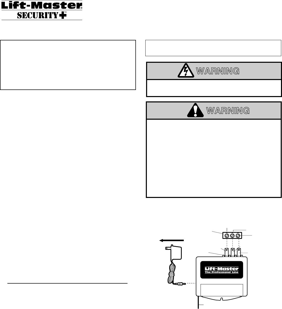
MOUNTING RECEIVER ON A COMMERCIAL OPENER
Fully extend antenna wire below bottom of case as shown.
Loosen the three terminal screws on the receiver (labeled 1, 2
and 3). Insert one end of a mounting clip under each terminal.
Do not retighten at this time.
Loosen the three terminal screws on the opener used for push
button controls and radio power.
Leaving the push button bell wire in place, insert the other ends
of the mounting clips under the opener terminal screws.
NOTE: If the number sequence of opener terminals
doesn't match the receiver, turn the receiver around (so
back is facing out) and complete the connection.
Retighten the terminal screws on opener and receiver.
Reconnect power to the opener. The receiver push bar should
light. If it does not, use Transformer Model 85.
Model 535LM Security✚
Receiver Only Model 535-2LM Security✚
(With 2 Remote Controls)
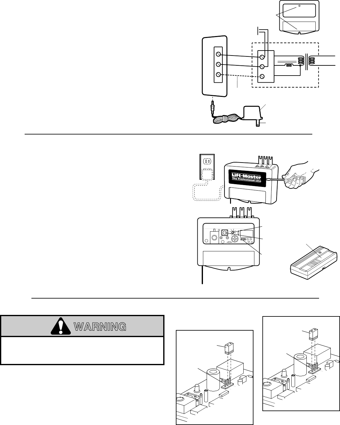
MOUNTING ON RESIDENTIAL OPENERS
Use a 2 wire connection
only.
Attach mounting clips to receiver
terminals 1 and 2, and to the opener terminals used for push
button controls. Plug the transformer into the receiver as
shown, and into a 120 Volt outlet.
Side two contains wall mounting instructions and code setting
instructions.
Children operating or playing with a garage door
opener can injure themselves and others.
The garage
door could close and cause serious injury or death.
Do
not allow children to operate the push buttons or the
remote control transmitters.
Install the receiver (and any additional push buttons)
out of the reach of children and away from all moving
parts of the door and door hardware, but
where the
garage door is visible.
A moving garage door could injure someone under it.
Activate the opener only when the door is properly
adjusted, you can see it clearly, and there are no
obstructions to door travel.
WARNING
CAUTION
WARNING
WARNING
AVERTISSEMENT
AVERTISSEMENT
Disconnect power to the garage door opener before
installing the receiver.
WARNING
CAUTION
WARNING
WARNING
AVERTISSEMENT
AVERTISSEMENT
To Outlet
Model 85
Transformer
OPENER
TERMINALS
Receiver
Terminals
Antenna Wire Fully Extended
Mounting
Clip #1
Mounting
Clip #2
Mounting
Clip #3
Common
Push Button
Radio Power
Vers prise de courant
Transformateur de
Modèle 85
Bornes de
l'ouvre-porte
Bornes du
récepteur
Fil d'antenne complètement étendu
Agrafe de
montage Nº1
Agrafe de
montage Nº2
Agrafe de
montage Nº3
(Facultatif)
©
©
Commun
Bouton-poussoir
Tension Radio
To comply with FCC/IC rules, adjustment or modification of receiver and/or
transmitter is prohibited, except for changing the code setting and replacing the
transmitter battery. THERE ARE NO USER SERVICEABLE PARTS.
NOTICE TO U. S. CONSUMERS:
Some states prohibit the service or repair of garage door openers which
cannot be made to comply with the safety standards contained in UL
325 (1988 revision). In order to comply with both the letter and the spirit
of these laws, this universal radio control should not be used with any
Lift-Master®, Chamberlain®, or Sears Craftsman®garage door opener
manufactured prior to April 1, 1982. To find out if your Chamberlain-
made garage door opener was manufactured prior to or after April 1,
1982, please call 1-800-528-9131 before installing this universal radio
control.
© 1996, The Chamberlain Group, Inc.
114A2139 All Rights Reserved Printed in Mexico
SET RECEIVER TO MATCH REMOTE CONTROL(S) CODE
Pry open the front panel of receiver case with a coin or a
screwdriver.
1. Press and
hold
the remote control push button.
2. Then press and release the "Smart" button on the receiver.
The adjacent indicator light will
flash
once. Release the
remote control push button.
The opener will now operate when the push button on either
the receiver or the remote control transmitter is pressed.
Repeat Steps 1 and 2 for each remote control that will be
used to operate the garage door opener.
NOTE: If the remote control push button is not held down
until the receiver indicator light flashes, the receiver will
not learn the code.
TO ERASE ALL REMOTE CONTROL CODES
• Press and hold the "Smart" code button on the receiver
panel until the indicator light turns off (about 6 seconds).
All
the codes the receiver has learned will be erased.
• Repeat Steps 1 and 2 to reprogram the receiver for each
remote control transmitter in use.
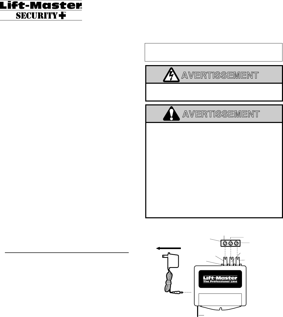
MOUNTING RECEIVER ON GARAGE WALL
Fully extend the antenna wire below bottom of case.
Fasten the receiver to an inside garage wall with dry wall
screws provided. A convenient place is alongside the service
door and
OUT OF THE REACH OF CHILDREN.
Attach one end of 3-strand bell wire (not supplied) to receiver
terminals 1, 2 and 3. Connect the other end to the three opener
terminals used for push button controls and radio power. Use
insulated staples to secure bell wire between receiver and
opener.
Reconnect power to the opener. The receiver push bar should
light. If it does not, use Transformer Model 85.
NOTE: With the transformer, use a 2-wire connection
only.
Attach wire to receiver terminals 1 and 2 and to the opener
terminals used for push button control. Plug the transformer
into receiver and 120 Volt outlet as shown.
To Wall Outlet
Model 85
Transformer
OPENER
WALL
PUSH
BUTTON
TRANS
PRIMARY
24v
1
2
3
Universal Radio
Control (Top)
Mounting Holes
Common
Push Button
Radio Pwr.
#3 Connection
(optional)
Bouton-poussoir
de l'émetteur
Bouton
"Smart"
Contacteur
de choix
Lampe
Témoin
Transmitter
Push Button
Indicator Light
Smart
Button
Option
Jumper
123
123
©
©
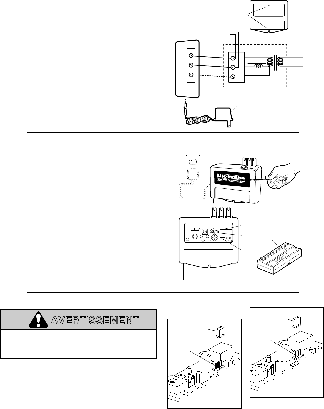
The receiver can be set for either constant or momentary
closure on the output contacts. With the jumper in the “MOM”
(Momentary) position, the contacts will close for 1/4 second
regardless of the length of radio transmission. With the jumper
in “CONST” (Constant) position, the contacts will stay closed
as long as the radio continues transmitting.
The receiver is factory set at M.
TO SET OUTPUT DURATION
The use of radios incorporating constant closure
contacts on residential operators with fail-safe infra-
red protectors is prohibited.
WARNING
CAUTION
WARNING
AVERTISSEMENT
ATTENTION
AVERTISSEMENT
The Chamberlain Group, Inc.
Output Duration Jumper
8/23/94
MOM.
CONST.
Output
Duration
Terminals
Circuit
Board
Jumper
CONSTANT
OPERATION
MOM.
CONST.
Output
Duration
Terminals
Circuit
Board
Jumper
MOMENTARY
OPERATION
MOM.
CONST.
Contacteur
OPÉRATION
CONSTANTE
MOM.
CONST.
Bornes de
durée de mise
sous tension
Carte de
circuit imprimé
Contacteur
OPÉRATION
MOMENTANÉE
Bornes de
durée de mise
sous tension
Carte de
circuit imprimé
Commande Radio Universelle
MANUEL D’UTILISATION
Avec SECURITY✚, le code entre la télécommande et le récepteur
change à chaque utilisation, accédant à plus de 100 milliards de
nouveaux codes de manière aléatoire.
On peut actionner l’ouvre-porte en utilisant plusieurs
télécommandes SECURITY✚(munies de témoins jaunes) utilisant
un nombre allant jusqu’à 8 fonctions, et un Système d’entrée sans
clé SECURITY✚.
Il se peut que le transformateur de modèle 85 soit requis si
votre ouvre-porte de garage est d’une marque autre que
LiftMaster, Chamberlain ou Sears.
REMARQUE: Le modèle 535-2LM est pré-réglé en usine avec des
codes émetteurs et récepteurs identiques.
IMPORTANT: Pour un maximum de sécurité et de portée,
mettre hors circuit la radio existante de l’ouvre-porte, sinon
elle pourrait encore actionner l’ouvre-porte:
• S’il y a un récepteur externe, le mettre hors tension.
• S’il s’agit d’un récepteur incorporé, détacher le composant qui
alimente le récepteur (se reporter à la Figure 1 pour les ouvre-
porte Lift-Master, Sears et Chamberlain) ou retirer le centre de
bobine de syntonisation et l’antenne de la section récepteur.
• Pour un ouvre-porte Lift-Master, Sears ou Chamberlain avec
récepteur “SMART”, effacer les anciens codes en appuyant sur
le bouton Smart pendant six secondes jusqu’à ce que le témoin
lumineux s’éteigne.
• Si on a des interrupteurs à code, les remettre à un code au
hasard et inhiber le récepteur en retirant le centre de bobine de
syntonisation et l’antenne.
LE RÉCEPTEUR PEUT ETRE INSTALLÉ DE DEUX FAÇONS:
1. Monté directement sur l’ouvre-porte à l’aide des agrafes
fournies comme décrit ci-dessous.
2. Attaché à un mur intérieur du garage à l’aide de fil de sonnette
(non fourni), comme décrit au verso.
Pour l’installation de deux ou plus récepteurs dans un garage, les
séparer d’au moins de 10 PIEDS afin d’éviter toute interférence
électronique.
MONTAGE DU RÉCEPTEUR SUR UN OUVRE-PORTE
COMMERCIAL
Étendre le fil d’antenne complètement sous le bas du boîtier tel
qu’illustré.
Désserrer les trois vis de bornes du récepteur (désignées 1, 2
et 3). Insérer une des extrémités d’une agrafe de montage
sous chaque borne.
Ne pas resserrer a présent.
Désserrer les trois vis de bornes de l’ouvre-porte qui sont
utilisées pour la commande de bouton-poussoir et la tension
radio.
Tout en laissant le fil de sonnette du bouton-poussoir à sa
place, insérer les autres extrémités des agrafes de montage
sous les vis des bornes de l’ouvre-porte.
REMARQUE: Si l’ordre dans lequel se trouvent les
numéros des bornes de l’ouvre-porte n’est pas le même
que sur le récepteur, retourner le récepteur (de façon que
l’arrière face l’extérieur) et finir le branchement. Resserrer
les vis de bornes de l’ouvre-porte et du récepteur. Rebrancher
le courant à l’ouvre-porte. La barre-poussoir du récepteur
devrait s’illuminer. Si elle ne s’illumine pas, utiliser le
Transformateur de Modèle 85.
Modèle 535LM Security✚
Récepteur seulement Modèle 535-2LM Security✚
(Avec 2 Télécommandes)
MONTAGE SUR OUVRE-PORTES RÉSIDENTIELS
N’utiliser qu’un branchement à 2 fils
seulement.
Attacher les
agrafes de montage aux bornes 1 et 2 du récepteur, et aux
bornes de l’ouvre-porte utilisées pour la commande de bouton-
poussoir. Brancher le transformateur dans le récepteur tel
qu’illustré, et dans une prise de courant de 120 Volts.
Au verso se trouvent des informations concernant le montage
mural et des instructions sur le réglage de code.
Les enfants faisant fonctionner ou jouant avec un
ouvre-porte de garage peuvent se blesser ou blesser
d’autres personnes.
La porte du garage pourait se
fermer et entraîner de sérieuses blessures ou la mort.
Ne pas laisser les enfants se servir du bouton-poussoir
du récepteur ou des émetteurs de commande à
distance.
Installer le récepteur (ainsi que touts bouton-poussoirs
supplémentaires) hors de portée des enfants et loin de
toute pièce de porte en mouvement, mais
là où la porte
de garage est visible.
Une porte de garage en mouvement pourait blesser
quelqu’un se trouvant en dessous de celle-ci.
N’activer
l’ouvre-porte que lorsque la porte est correctement
réglée, que vous pouvez la voir clairement, et qu’elle
est libre de toute obstruction.
WARNING
CAUTION
WARNING
WARNING
AVERTISSEMENT
AVERTISSEMENT
Débrancher le courant de l’ouvre-porte de garage avant
d’installer le récepteur.
WARNING
CAUTION
WARNING
WARNING
AVERTISSEMENT
AVERTISSEMENT
To Outlet
Model 85
Transformer
OPENER
TERMINALS
Receiver
Terminals
Antenna Wire Fully Extended
Mounting
Clip #1
Mounting
Clip #2
Mounting
Clip #3
Common
Push Button
Radio Power
Vers prise de courant
Transformateur de
Modèle 85
Bornes de
l'ouvre-porte
Bornes du
récepteur
Fil d'antenne complètement étendu
Agrafe de
montage Nº1
Agrafe de
montage Nº2
Agrafe de
montage Nº3
(Facultatif)
©
©
Commun
Bouton-poussoir
Tension Radio
Les règlements de l’Industrie Canada interdisent le réglage ou la modification des
circuits des émetteurs et des récepteurs, sauf lorsqu'il s'agit de remplacer la pile de
l'émetteur. AUCUNE PIÉCE N'EST RÉPARABLE PAR L'UTILISATEUR.
© 1996, The Chamberlain Group, Inc.
114A2139 Touts Droits Réservés Imprimé au Mexique
RÉGLAGE DU RÉCEPTEUR AU CODE DE TÉLÉCOMMANDE(S)
Soulever le paneau frontal du boîtier du récepteur avec une
pièce de monaie ou un tournevis.
1. Appuyer et
maintenir
le bouton-poussoir de l’émetteur.
2. Ensuite appuyer puis relâcher le bouton «Smart» du
récepteur. La lampe témoin adjacente
clignotera
une fois.
Relâcher le bouton-poussoir de la télécommande.
L’ouvre-porte fonctionnera désormais lorsque le bouton-
poussoir du récepteur ou de l’émetteur est appuyé.
Répéter les étapes 1 et 2 pour chaque émetteur qui sera
utilisé avec l’ouvre-porte de garage.
REMARQUE: Si le bouton-poussoir de la télécommande
n’est pas maintenu appuyé jusqu’à ce que la lampe témoin
du récepteur clignote, le récepteur n’apprend pas le code.
POUR EFFACER TOUS LES CODES D’ÉMETTEURS
• Appuyer et maintenir le bouton de code «Smart» sur le
paneau de l’ouvre-porte jusqu’à ce que la lampe témoin
s’éteigne (environ 6 secondes).
Tous
les codes appris par
l’ouvre-porte seront effacés.
• Répéter les étapes 1 et 2 pour reprogrammer le récepteur
pour chaque émetteur en usage.
MONTAGE DU RÉCEPTEUR AU MUR DU GARAGE
Étendre complètement le fil d’antenne sous le bas du boîtier.
Attacher le récepteur à un mur intérieur du garage avec les vis
fournies. Un endroit pratique est au long de la porte de service
et
HORS DE PORTÉE DES ENFANTS
.
Brancher une des extrémités du fil de sonnette à 3 conducteurs
(non fourni) aux bornes 1, 2 et 3. Brancher l’autre extrémité
aux trois bornes de l’ouvre-porte qui sont utilisés pour la
commande de bouton-poussoir et la tension radio. Utiliser les
agrafes isolées pour maintenir le fil de sonnette entre le
récepteur et l’ouvre-porte.
Rebrancher le courant à l’ouvre-porte. La barre-poussoir du
récepteur devrait s’illuminer. Si elle ne s’illumine pas, utiliser le
Transformateur de Modèle 85.
REMARQUE: Avec le transformateur, n’utiliser un
branchement qu’à 2 fils
seulement.
Attacher le fil aux bornes 1
et 2 du récepteur, et aux bornes de l’ouvre-porte utilisées pour
la commande de bouton-poussoir. Brancher le transformateur
dans le récepteur et dans une prise de courant de 120 Volts tel
qu’illustré.
Vers Prise de Courant
Transformateur
de Modèle 85
OUVRE-PORTE
BOUTON-
POUSSOIR
MURAL
TRANSFORMATEUR
PRIMAIRE
24v
1
2
3
Commande Radio
Universelle (dessus)
Commun
Bouton-
Poussoir
Tension
Radio
Connection Nº3
(facultatifl)
Trous de Montage
Bouton-poussoir
de l'émetteur
Bouton
"Smart"
Contacteur
de choix
Lampe
Témoin
Transmitter
Push Button
Indicator Light
Smart
Button
Option
Jumper
123
123
©
©
Le récepteur peut être réglé pour fermeture des contacts de
mise sous tension soit constante ou momentanée. Avec le
contacteur en position “MOM” (Momentary), les contacts se
fermeront pendant 1/4 de seconde indépendamment de la
durée de transmission radio. Avec le contacteur en position
“CONST” (Constant), les contacts resteront fermés tant que la
radio continue à transmettre.
Le récepteur est réglé en usine à M.
RÉGLAGE DE LA DURÉE DE MISE SOUS TENSION
L’utilisation de radios contenant des contacts à fermeture
constante sur des ouvre-portes résidentiels avec des
protecteurs de sécurité infra-rouges est interdite.
WARNING
CAUTION
WARNING
AVERTISSEMENT
ATTENTION
AVERTISSEMENT
The Chamberlain Group, Inc.
Output Duration Jumper
8/23/94
MOM.
CONST.
Output
Duration
Terminals
Circuit
Board
Jumper
Constant Operation
MOM.
CONST.
Output
Duration
Terminals
Circuit
Board
Jumper
Momentary Operation
Bornes de
durée de mise
sous tension
Contacteur
OPÉRATION
CONSTANTE
OPÉRATION
MOMENTANÉE
MOM.
CONST.
MOM.
CONST.
Carte de
circuit imprimé
Contacteur
Bornes de
durée de mise
sous tension
Carte de
circuit imprimé