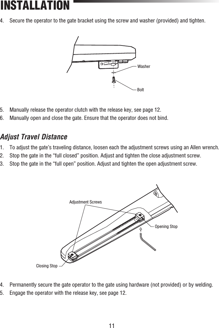
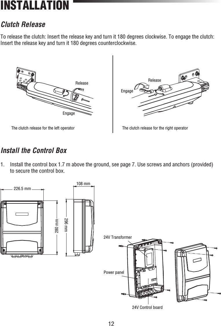
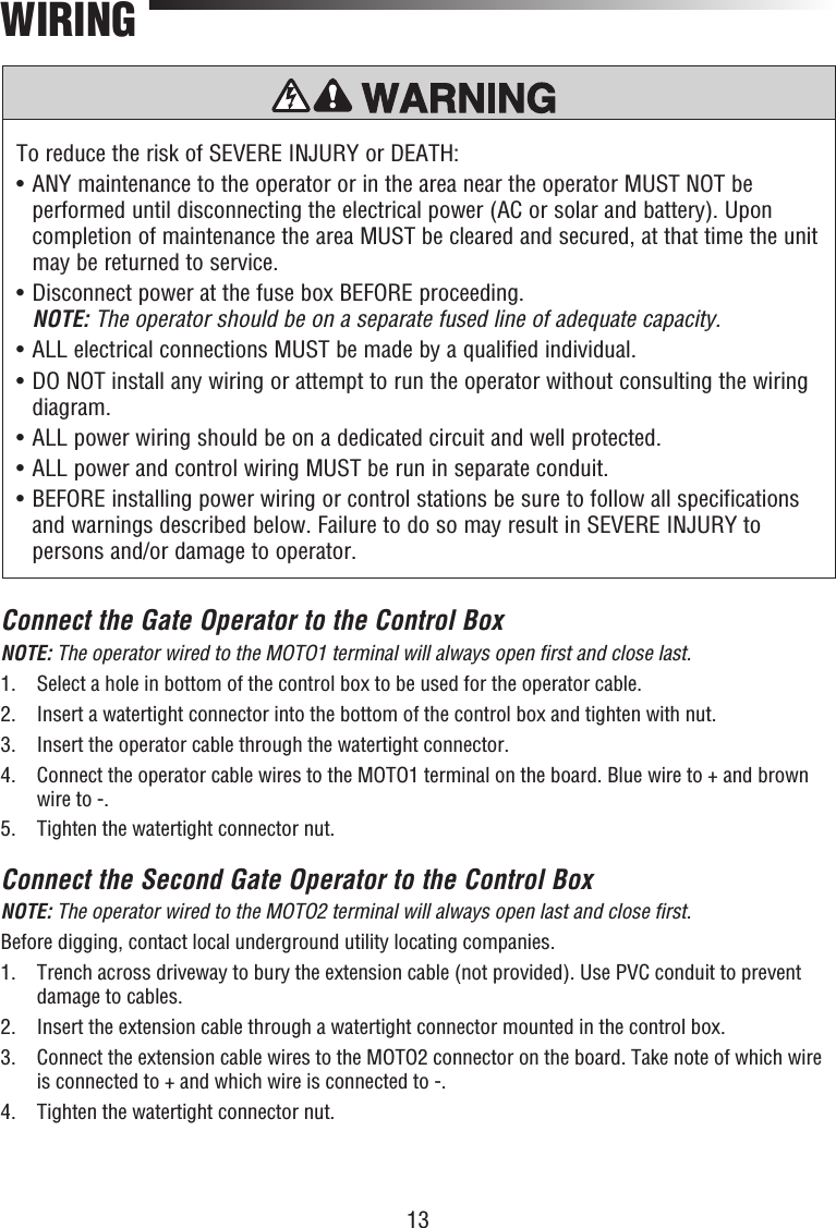
Chamberlain Group The 350 Swing Gate Operator User Manual 01 36883D indd

Chamberlain Group Inc, The Swing Gate Operator 01 36883D indd

Manual

PLEASE READ THE MANUAL CAREFULLY BEFORE INSTALLATION AND OPERATIONTHIS PRODUCT TO BE INSTALLED BY A TRAINED GATE SYSTEMS TECHNICIAN ONLY. LA350SWING GATE OPERATORINSTALLATION MANUAL
2TABLE OF CONTENTSSAFETY ................................................................................................................................................ 3-5INTRODUCTIONSpecifications ...........................................................................................................................................6Carton Inventory ......................................................................................................................................6Tools Needed ...........................................................................................................................................7Overview of Gate Operator and Wiring for Control Box ...........................................................................7INSTALLATIONDetermine the Position of the Post Bracket .............................................................................................8Dimensions of Gate Operator ...................................................................................................................9Determine the Position of the Gate Bracket ..................................................................................... 10-11Adjust Travel Distance ...........................................................................................................................11Clutch Release .......................................................................................................................................12Install the Control Box ...........................................................................................................................12WIRINGConnect the Gate Operator to the Control Box .......................................................................................13Connect the Second Gate Operator to the Control Box ..........................................................................13Voltage Selection ...................................................................................................................................14Power Wiring .........................................................................................................................................14Connect a Battery Backup to the Control Box (Optional) .......................................................................16Wiring Diagram ......................................................................................................................................17TRAVEL LIMIT SETTINGS ...................................................................................................................... 18PROGRAMMINGProgram Remote Control .......................................................................................................................18Erase All Codes ......................................................................................................................................18LiftMaster® Internet Gateway .................................................................................................................19Erase a LiftMaster® Internet Gateway ....................................................................................................19SETTINGSOpening/Closing Delay Time Settings ....................................................................................................20Single Gate Leaf Operation Setting ........................................................................................................20Operation Mode Setting .........................................................................................................................20Auto Closing Setting ..............................................................................................................................20Force Adjustment ...................................................................................................................................21Soft Start and Stop Speed Setting .........................................................................................................21Moving Speed Setting ............................................................................................................................21Operating Time Setting ..........................................................................................................................21Maglock (Optional) ................................................................................................................................22Flashing Light (Optional) .......................................................................................................................22The Photoelectric Sensor (Optional) Connection ...................................................................................22OPERATION AND MAINTENANCE .................................................................................................... 23-25TROUBLESHOOTING .............................................................................................................................26SERVICE KITS ........................................................................................................................................27ACCESSORIES .......................................................................................................................................27
3MECHANICALELECTRICALWhen you see these Safety Symbols and Signal Words on the following pages, they will alert you to the possibility of serious injury or death if you do not comply with the warnings that accompany them. The hazard may come from something mechanical or from electric shock. Read the warnings carefully.When you see this Signal Word on the following pages, it will alert you to the possibility of damage to your gate and/or the gate operator if you do not comply with the cautionary statements that accompany it. Read them carefully.Safety Precautions For Swing and Ornamental Grill Type GatesSAFETYTo prevent SERIOUS INJURY or DEATH from a moving gate:•  Entrapment protection devices MUST be installed to protect anyone who may come near a moving gate.•  Locate entrapment protection devices to protect in BOTH the open and close gate cycles.•  Locate entrapment protection devices to protect between moving gate and RIGID objects, such as posts.• A swinging gate shall NOT open into public access ways.• SAVE THESE INSTRUCTIONS.We recommend to use E-locks/Maglock against vandalism and if gate is installed where strong winds may appear.IMPORTANT NOTE•   BEFORE attempting to install, operate or maintain the operator, you must read and fully understand this manual and follow all safety instructions.•   These instructions are intended to highlight certain safety related issues. These instructions are not intended to be comprehensive. Because each application is unique, it is the responsibility of the purchaser, designer, installer and end user to ensure that the total gate system is safe for its intended use.•  Save These Instructions.
4To reduce the risk of SEVERE INJURY or DEATH from an incorrect installation:1.  Vehicular gate systems provide convenience and security. Gate systems are comprised of many component parts. The gate operator is only one component. Each gate system is specifically designed for an individual application.2.  Gate operating system designers, installers and users must take into account the possible hazards associated with each individual application. Improperly designed, installed or maintained systems can create risks for the user as well as the bystander. Gate systems design and installation must reduce public exposure to potential hazards.3.  A gate operator can create high levels of force in its function as a component part of a gate system. Therefore, safety features must be incorporated into every design. Specific safety features include:  • Gate Edges •  Guards for exposed rollers •  Photoelectric Sensors  • Screen Mesh •  Vertical Posts •  Instructional and Precautionary Signage4.  Install the gate operator only when:  a. The operator is appropriate for the construction and the usage of the gate.  b.  All openings of a horizontal swing gate are guarded or screened from the bottom of the gate to a minimum of 4’ (1.2 m) above the ground to prevent a 2 1/4" (6 cm) diameter sphere from passing through the openings anywhere in the gate, and in that portion of the adjacent fence that the gate covers in the open position.  c.  All exposed pinch points are eliminated or guarded, and guarding is supplied for exposed rollers.5.  The operator is intended for installation on gates used for vehicles. Pedestrians should be supplied with a separate access opening.6.  The gate must be installed in a location so that enough clearance is supplied between the gate and adjacent structures when opening and closing to reduce the risk of entrapment. Swinging gates shall not open into public access areas.7.  The gate must be properly installed and work freely in both directions prior to the installation of the gate operator.8.  Controls must be far enough from the gate so that the user is prevented from coming in contact with the gate while operating the controls.SAFETYIMPORTANT SAFETY INFORMATION
5SAFETY9. For a gate operator utilizing a non-contact sensor:  a.  Reference owner’s manual regarding placement of non-contact sensor for each type of application.  b.  Care shall be exercised to reduce the risk of nuisance tripping, such as when a vehicle trips the sensor while the gate is still moving.  c.  One or more non-contact sensors shall be located where the risk of entrapment or obstruction exists, such as the perimeter reachable by a moving gate or barrier.10. For a gate operator utilizing a contact sensor such as an edge sensor:  a.  A hard wired contact sensor shall be located and its wiring arranged so the communication between the sensor and the gate operator is not subject to mechanical damage.  b.  A wireless contact sensor such as the one that transmits radio frequency (RF) signals to the gate operator for entrapment protection functions shall be located where the transmission of the signals are not obstructed. A wireless contact sensor shall function under the intended end-use conditions.  c.  One or more contact sensors shall be located on the inside and outside leading edge of a swing gate. Additionally, if the bottom edge of a swing gate is greater than 6" (15 cm) above the ground at any point in its arc of travel, one or more contact sensors shall be located on the bottom edge.IMPORTANT SAFETY INFORMATIONIMPORTANT: The MyQ feature and its accessories are not permitted for use in the countries of Peru and Chile.
6SpecificationsINTRODUCTIONCarton InventoryMain AC Supply: 110-127Vac / 220-240Vac; 50/60HzMotor Voltage: 24 VdcInput Power: 100 WAmbient Temperature Range: -25 ~ +50 ˚CMaximum Weight for single Gate Leaf: 350 KgMaximum Width for single Gate Leaf: 1.8 m, 2.5 m (with electric lock)Maximum Open Angle: 120˚Protection Level: IP 44Maximum Travel Distance: 350 mmDaily Cycle Rate: Maximum 50 cycles per dayWeight per Gate Operator: 6 KgInstallation Manual(Not shown)Remote Control (2)Post Mounting Bracket (2) Gate Mounting Bracket (2)Washer and Bolt (attached to the arm)Control BoxRelease Key (3) Hairpin Clip (2)Clevis Pin (2) M8x60 Screws (8)OperatorModel LA350 (2)
7 Overview of Gate Operator and Wiring for Control BoxTools NeededLA350Gate Operatorwith 1000 mmcableCable for Photoelectric Sensor: 4 X O.5 mm2 or 2 X O.5 mm2 (optional)Extension Cables for MOTO2:2 X 1.0 mm2(not supplied)Cable for Flashing Light: 2 X 1.O mm2  (optional)Remote ControlFA42LM Flashing Light (optional)FA70LM Control BoxLA350Gate Operatorwith 1000 mmcablePower Cable: 2 X 1.5 mm2Cables forMOTO1& MOTO2:2 X 1.0 mm2FA31LM Photoelectric Sensor (optional)Cable for PhotoelectricSensor: 4 X O.5 mm2 or 2 X O.5 mm2 (optional)Junction Box(not supplied)FA31LM Photoelectric Sensor (optional)Cables used must meet all National and Local Codes for outdoor use.INTRODUCTION
8Determine the Position of the Post Bracket1.  Measure the Value C.2.  Value D will depend on the position where the post bracket is mounted.3.  Value A is the total length for both C and D.4.   Value B will depend on Value A and the maximum opening angle of the gate. Refer to Table 1 below. NOTE: For optimal mechanical advantage Value B must be close or equal to Value A. 5.   Determine the A and B measurements provided in Table 1 to confi rm the position where the post bracket will be mounted.ABDCGateGate OperatorPost BracketGate BracketGate Post100   110   120   130   140   150   160   170   180   190   200100110120130140150160170180190200Max 120˚Max 110˚Max 100˚Max 90˚ABUnit = mmTable 1 Maximum Gate OpeningINSTALLATION
96.   Using the post bracket as a reference, mark and drill the holes for the post bracket.7.  Attach the post bracket with the M8x60 screws, washers, and nuts.8.   The slots on the post bracket allow for alignment. When the post bracket is level tighten the nuts.Level Drill hole M8x60 screwWashersNut55 mm115.3 mm93.5 mm95 mm835 mm350 mmDimensions of Gate OperatorINSTALLATION
10730 mm38 mmDetermine the Position of the Gate Bracket1.    Position the gate bracket 730 mm from the post bracket and 38 mm lower than the post bracket.2.  Temporarily secure the gate bracket to the gate with a clamp.3.   Align the hole on the operator fork to the post bracket hole. Attach the operator to the post bracket using the clevis pin and secure with a hairpin clip.Level rulerWhen installing the gate bracket, the washer should face downward.INSTALLATION
114.   Secure the operator to the gate bracket using the screw and washer (provided) and tighten.4.   Permanently secure the gate operator to the gate using hardware (not provided) or by welding.5.  Engage the operator with the release key, see page 12.5.  Manually release the operator clutch with the release key, see page 12.6.  Manually open and close the gate. Ensure that the operator does not bind. Adjust Travel Distance 1.   To adjust the gate’s traveling distance, loosen each the adjustment screws using an Allen wrench.2.  Stop the gate in the “full closed” position. Adjust and tighten the close adjustment screw.3.  Stop the gate in the “full open” position. Adjust and tighten the open adjustment screw.Adjustment ScrewsClosing StopOpening StopWasherBoltINSTALLATION
12To release the clutch: Insert the release key and turn it 180 degrees clockwise. To engage the clutch: Insert the release key and turn it 180 degrees counterclockwise. Clutch  ReleaseReleaseEngageReleaseEngageThe clutch release for the left operator The clutch release for the right operatorINSTALLATION1.   Install the control box 1.7 m above the ground, see page 7. Use screws and anchors (provided) to secure the control box.24V Transformer24V Control boardPower panelInstall the Control Box226.5 mm280 mm108 mm296 mm
13To reduce the risk of SEVERE INJURY or DEATH:•  ANY maintenance to the operator or in the area near the operator MUST NOT be performed until disconnecting the electrical power (AC or solar and battery). Upon completion of maintenance the area MUST be cleared and secured, at that time the unit may be returned to service.•  Disconnect power at the fuse box BEFORE proceeding. NOTE: The operator should be on a separate fused line of adequate capacity.•  ALL electrical connections MUST be made by a qualified individual.•   DO NOT install any wiring or attempt to run the operator without consulting the wiring diagram. •   ALL power wiring should be on a dedicated circuit and well protected. •  ALL power and control wiring MUST be run in separate conduit.•   BEFORE installing power wiring or control stations be sure to follow all specifications and warnings described below. Failure to do so may result in SEVERE INJURY to persons and/or damage to operator.WIRINGConnect the Gate Operator to the Control BoxNOTE: The operator wired to the MOTO1 terminal will always open fi rst and close last.1.  Select a hole in bottom of the control box to be used for the operator cable.2.  Insert a watertight connector into the bottom of the control box and tighten with nut.3.  Insert the operator cable through the watertight connector.4.   Connect the operator cable wires to the MOTO1 terminal on the board. Blue wire to + and brown wire to -.5.  Tighten the watertight connector nut.Connect the Second Gate Operator to the Control BoxNOTE: The operator wired to the MOTO2 terminal will always open last and close fi rst. Before digging, contact local underground utility locating companies.1.   Trench across driveway to bury the extension cable (not provided). Use PVC conduit to prevent damage to cables.2.  Insert the extension cable through a watertight connector mounted in the control box.3.   Connect the extension cable wires to the MOTO2 connector on the board. Take note of which wire is connected to + and which wire is connected to -.4.  Tighten the watertight connector nut.
145.   Mount a watertight junction box (not provided) that is able to accommodate two watertight connectors (not provided) within 3 feet (0.9 m) of the second operator.6.  Remove the cover from the watertight junction box and set aside.7.  Route the operator cable through a watertight connector into the junction box.8.  Route the extension cable through a watertight connector into the junction box.9.   Connect the wires from the operator and the extension cable inside the junction box. Connect the blue wire from the operator to the extension cable wire connected to the + terminal on the board. Connect the brown wire from the operator to the extension cable wire connected to the - terminal on the board.10.  Tighten the watertight connector nuts.11.  Reinstall the cover on the watertight junction box.Voltage SelectionThe operator can be wired for either 110-127 Vac or 220-240 Vac through a jumper setting.NOTE: The factory default setting is 220 Vac.For 110-127 Vac installations:1.  Turn off the AC power from the main power source circuit breaker.2.   Place the jumper on J3 and the cover on J2 on the control board.For 220-240 Vac installations:1.  Turn off the AC power from the main power source circuit breaker.2.   Place the jumper on J2 and the cover on J3 on the control board.Power WiringThe operator can be wired for either 110-127 Vac or 220-240 Vac.1.  Turn off the AC power from the main power source circuit breaker.2.  Select a hole in bottom of the control box to be used for the incoming AC power.3.   Insert a watertight connector into the bottom of the control box and tighten with nut.4.  Insert the AC power wires through the watertight connector.5.  Connect the “hot” wire to the L terminal on the board.6.  Connect the neutral wire to the N terminal on the board.7.  Tighten the watertight connector nut.8.  Restore power to the control box.WIRINGTo reduce the risk of SEVERE INJURY or DEATH:• DO NOT TOUCH the unused connections on J2 or J3 as they are energized. • Replace cover before reconnecting or connecting power.
15WIRING110-127 VacOFFONONOFFJ3J2230V127VNPOWER LINEGNDGNDS1COM S2COMIAD:1IAD:2VCCADRP3RP1RP2RP4+++-- -BATAD+24V+3.3V+5VCHARVCC33VPbET-LA350-R  NO.06 2013.9.20432187654321 OFFON-BATTERY+24V AC INCharging+MOTO2- Gate1Gate2GNDIR2IR1GNDIR.V+GNDDC.L+Lock++MOTO1-Transformer InNLSBCLEARNFORCERV LVTIMERSBC1SBCIR2IR1220-240 VacIndicatorJ3J2R78R77R80IC6VT2-BVT1-BQ18RP3C30D33SW1D8R75R72R70R73R71R68Q15Q17Q14LED2LED3LED1SW3C32C1C2C5C6C7C8C9C10C11C12C13C14C17C19C20C21C22C23C24C25C29C31C33C35C36C37C38C39C40C41C42C43CON1CON2CON5CON6CON7D1D2D3D4D5D6D7 D9D10D11D12D13D14D15D16D17D18D19D20D21D22D23D24D25D26D27D36D29D30D31D32D34D35DB1DZ2DZ1IC1IC2IC3IC4IC5J1K1K2K3K4L1LED4LED5LED6LED7LED8Q1Q2 Q3Q4Q5Q6Q7 Q8Q9Q12Q11Q13Q16Q19R1R2R3R4R5R6R7R8R9R10R11R12R13R14R15R16R17R18R19 R20R21R22R23R24R25R26R27R28R29R30R31R32R33R34R35R36R37R38R39 R40R41R43R44R45R46R47R48R49R50R51R52R53R54R55R56R57 R58R59R60R62R61R64R63R65R66 R67R69R74R76RF1RP1RP2RP4S1 S2U1VT1VT2C18CON4RV1CON3DZ3R10011MMLNPOWER IN24V DC Motor LOCK  DC LampIR TX IR RX1,2Gate1,224V Battery24V TransformerBrownBlueBrownBlue
16WIRINGCONTROL BOARD Jumper with10A/250V in-line fuse(not supplied) Connect a Battery Backup to the Control Box (Optional)The batteries are charged in the circuit by the integrated transformer. Recommended items for a battery backup application (not provided):  •  Two 12V 4Ah batteries (McNair Model RB-FM-12V-4AH)   •  Battery box (Attwood Model 9069-1)  •  3 x 18 AWG (1.00 mm) VM-1 105°C 600V, 1 wire must have a 10A/250V in-line fuse1.  Disconnect/turn OFF AC power to the operator.2.   Select a hole in the bottom of the control box to be used for the battery backup cable (not provided).3.   Insert a watertight connector (not provided) into the bottom of the control box and tighten with nut.4.   Insert the battery cable through the watertight connector mounted in the bottom of the control box.5.  Connect the battery cable to the BATTERY terminal on the control board.6.  Tighten the watertight connector nut.7.  Install battery box in desired location (no further than 10’ away).9.  Place the batteries in the battery box. 10.   Connect a jumper with an in-line fuse between the positive (+) terminal on one battery and the negative (-) terminal on the other battery.11.  Connect the positive battery cable wire to the positive (+) terminal on the battery.12.  Connect the negative battery cable wire to the negative (-) terminal on the other battery.13.  Reconnect/turn ON AC power to the operator.
17110-127 VacOFFONONOFFJ3J2230V127VNPOWER LINEGNDGNDS1COM S2COMIAD:1IAD:2VCCADRP3RP1RP2RP4+++-- -BATAD+24V+3.3V+5VCHARVCC33VPbET-LA350-R  NO.06 2013.9.20432187654321 OFFON-BATTERY+24V AC INCharging+MOTO2-Gate1Gate2GNDIR2IR1GNDIR.V+GNDDC.L+Lock++MOTO1-Transformer InNLSBCLEARNFORCERV LVTIMERSBC1SBCIR2IR1220-240 VacIndicatorJ3J2R78R77R80IC6VT2-BVT1-BQ18RP3C30D33SW1D8R75R72R70R73R71R68Q15Q17Q14LED2LED3LED1SW3C32C1C2C5C6C7C8C9C10C11C12C13C14C17C19C20C21C22C23C24C25C29C31C33C35C36C37C38C39C40C41C42C43CON1CON2CON5CON6CON7D1D2D3D4D5D6D7 D9D10D11D12D13D14D15D16D17D18D19D20D21D22D23D24D25D26D27D36D29D30D31D32D34D35DB1DZ2DZ1IC1IC2IC3IC4IC5J1K1K2K3K4L1LED4LED5LED6LED7LED8Q1Q2 Q3Q4Q5Q6Q7 Q8Q9Q12Q11Q13Q16Q19R1R2R3R4R5R6R7R8R9R10R11R12R13R14R15R16R17R18R19 R20R21R22R23R24R25R26R27R28R29R30R31R32R33R34R35R36R37R38R39 R40R41R43R44R45R46R47R48R49R50R51R52R53R54R55R56R57 R58R59R60R62R61R64R63R65R66 R67R69R74R76RF1RP1RP2RP4S1 S2U1VT1VT2C18CON4RV1CON3DZ3R10011MMLNPOWER IN24V DC Motor LOCK  DC LampIR TX IR RX1,2 Gate1,224V Battery24V TransformerBrownBlueBrownBlueWIRING Wiring  DiagramSBC is an open/close command for a single gate.NOTE: SBC is also used for the travel limit setting in conjunction with the S1 No. 8 in the ON position.
181.   Release the clutch on both operators with the release key. Open both gates completely, then engage the clutches. 2.  Set DIP switch S1 No. 8 to ON position.3.  Press button          on the control board, both    gate leaves will close completely.4.  Press button          again, both gate leaves will open completely.5.  Set DIP switch S1 No. 8 to OFF position.ONOFF1   2   3   4   5   6   7   8S1SBCSBCTRAVEL LIMIT SETTINGSPROGRAMMINGNOTICE: Operation is subject to the following two conditions: (1) this device may not cause harmful interference, and (2) this device must accept any interference received, including interference that may cause undesired operation.Any changes or modifi cations not expressly approved by the party responsible for this product could void the user’s authority to operate the equipment.This device is designed to provide reasonable protection against harmful interference in a residential installation. This equipment generates, uses and can radiate radio frequency energy and, if not installed and used in accordance with the instructions, may cause harmful interference to radio communications. However, there is no guarantee that interference will not occur in a particular installation. If this equipment does cause harmful interference to radio or television reception, which can be determined by turning the equipment off and on, the user is encouraged to:- Connect the equipment into an outlet on a circuit different from that to which the receiver is connected.- Consult the dealer or an experienced radio/TV technician for help. Program Remote Control1.  Press and release the LEARN button          , LED1 will light. 2.  Press the desired button on the remote control to program it to the operator. The operator will automatically exit learn mode (LED1 will fl ash and go out) if programming is successful. To program additional Security✚ 2.0™ remote controls or remote control buttons, repeat the programming steps above. Press the LEARN button a second time to exit programming at any time.LEARNErase All Codes1.  Press and hold the LEARN button          , LED1 will light. 2.   Hold the LEARN button for approximately 6 seconds. LED1 will go out and all remote control codes are now erased.LEARNThe antenna(s) used for this must be installed to provide a separation distance of at least 20 cm from all persons and must not be collocated The antenna(s) used for this must be installed to provide a separation distance of at least 20 cmfrom all persons and must not be collocated or operatingor operating in conjunction with any other antenna or transmitter, except in accordance with FCC multi-transmitter product procedures.
19PROGRAMMINGLiftMaster® Internet GatewayTo program the operator to the LiftMaster® Internet Gateway:1.  Connect the Ethernet cable to the LiftMaster® Internet Gateway and the router.2.  Connect power to the LiftMaster® Internet Gateway.3.  Create an online account by visiting www.myliftmaster.com.4.  Register the LiftMaster® Internet Gateway.5.   Use an internet enabled computer or smartphone to add devices. The LiftMaster® Internet Gateway will stay in learn mode for three minutes.6.   Press the LEARN button on the operator (LED1 will light as it enters learn mode). The LiftMaster® Internet Gateway will pair to the operator if it is within range and LED1 will fl ash and go out if programming is successful.Erase a LiftMaster® Internet Gateway1.  Press and hold the LEARN button          , LED1 will light. 2.   Hold the LEARN button for approximately 6 seconds. LED1 will go out and all remote control codes are now erased.3.  Press and hold the LEARN button a second time, LED1 will light again.4.   Hold the LEARN button for approximately 6 seconds. LED1 will go out and all gateways are now erased.LEARN
20Opening/Closing Delay Time Setting  Factory default is set at 2 seconds.   The Open/Closing Delay times can be individually set from 1-4 seconds. Opening Delay:  1 OFF and 2 OFF = 1 second  1 ON and 2 OFF = 2 seconds  1 OFF and 2 ON = 3 seconds  1 ON and 2 ON = 4 seconds  The minimum delay time is 1 second. Closing Delay:  3 OFF and 4 OFF = 1 second  3 ON and 4 OFF = 2 seconds  3 OFF and 4 ON = 3 seconds  3 ON and 4 ON = 4 seconds  The minimum delay time is 1 second.Single Gate Leaf Operation Setting  5 ON = Only MOTO1 operator is available.  5 OFF = Both MOTO1 and MOTO2 operators are available.Operation Mode Setting  6 ON =  The operation mode is :OPEN-STOP-CLOSE-OPEN  6 OFF =  The operation mode is:OPEN-STOP-CLOSE-STOP-OPEN Auto Close Time Setting  Factory default for this function is OFF. The time can be set   from 0-105 seconds.  1 = 15s     2 = 30s     3 = 60s   If all the DIP switches are set to the ON position, the auto closing time is 105 seconds. If all the DIP switches are set to the OFF position, the gate leaf will not close automatically.ONOFF1   2   3   4   5   6   7   8S1Opening Delay set for 4 secondsSETTINGSMOTO1 onlyOPEN - STOP - CLOSE - OPEN  ONOFFS21    2    3   4ONOFF1   2   3   4   5   6   7   8S1ONOFF1   2   3   4   5   6   7   8S1ONOFF1   2   3   4   5   6   7   8S1ONOFF1   2   3   4   5   6   7   8S1Closing Delay set for 4 seconds
21Force Adjustment   Turn the FORCE button clockwise to make the driving force of the gate stronger. Turn the FORCE button counterclockwise to make the driving force of the gate weaker.Soft Start and Stop Speed Setting   Turn the LV button clockwise to increase the speed. Turn the LV button counterclockwise to decrease the speed. Moving Speed Setting   Turn RV button clockwise to increase the speed of the gate. Turn the RV button counterclockwise to decrease the speed of the gate. Operating Time Setting   Turn the TIMER button clockwise for longer operating time. Turn TIMER button counterclockwise, for shorter operating time. The time can be set from a maximum of 60 seconds to a minimum of 30 seconds.WeakerStrongerLVRV FORCETIMERLVRV FORCETIMERLVRV FORCETIMERSlowerFasterSlowerFasterSETTINGSShorterLongerLVRV FORCETIMER
22Maglock (Optional)   The LOCK and GND connectors on the board are for the MG1300 MAGLOCK (24V/250 mA). When the maglock is connected, the lock will disengage before the gate opens.Flashing Light (Optional)   The DCL and GND connectors on the board are for the FA42LM fl ashing light. The fl ashing light will turn on before the gate opens.The Photoelectric Sensor (Optional) Connection   The connection for the photoelectric sensor is a normal closed. If the operator is installed without photoelectric sensors, connect the IR1 terminal to the GND terminal with a jumper and connect the IR2 terminal to the GND terminal with a jumper, otherwise the operator will not function properly. The jumpers are installed from the factory. If IR1 or IR2 is used, leave the other pair of terminals connected with a jumper.   When the beam of a photoelectric sensor IR1 is interrupted by obstacles, the gate will stop and reverse during closing or stop during opening. IR1 LED on the control board will turn off. When the beam of a photoelectric sensor IR2 is interrupted by obstacles, the gate leaf will stop in either direction. IR2 LED on the control board will turn off.SETTINGS
23OPERATION AND MAINTENANCE•  READ AND FOLLOW ALL INSTRUCTIONS.•  NEVER let children operate or play with gate controls. Keep the remote control away from children.•  ALWAYS keep people and objects away from the gate. NO ONE SHOULD CROSS THE PATH OF THE MOVING GATE.•  Test the gate operator monthly. The gate MUST reverse on contact with a rigid object or stop when an object activates the non-contact sensors. After adjusting the force or the limit of travel, retest the gate operator. Failure to adjust and retest the gate operator properly can increase the risk of INJURY or DEATH.•  Use the emergency release ONLY when the gate is not moving.•  KEEP GATES PROPERLY MAINTAINED. Read the owner’s manual. Have a qualified service person make repairs to gate hardware.•  The entrance/exit is intended for vehicles. Pedestrians should be supplied with a separate access opening.•  Activate gate ONLY when it can be seen clearly, is properly adjusted and there are no obstructions to gate travel.•  Locate entrapment protection devices to protect in BOTH the open and close gate cycles. •  SAVE THESE INSTRUCTIONS.IMPORTANT SAFETY INSTRUCTIONS
24To reduce the risk of SEVERE INJURY or DEATH:•  Disconnect ALL power BEFORE performing ANY maintenance.• ALL maintenance MUST be performed by a LiftMaster® professional.•  ALWAYS wear protective gloves and eye protection when changing the battery or working around the battery compartment.MaintenanceOPERATION AND MAINTENANCECHECK AT LEAST ONCE EVERYDESCRIPTION TASK MONTH 3 MONTHS 6 MONTHS 12 MONTHSExternal entrapment protection systemsCheck for proper operation •Complete Check OutGate warning signs Make sure they are present •Manual release Check and operate •Gate Inspect for wear or damage •Accessories Check all for proper operation •Electrical Inspect all wire connections •Total unit Inspect for wear or damage •Maintenance Chart
25OPERATION AND MAINTENANCEThere are different kinds of materials in a gate operator. Some can be recycled, such as aluminum, iron, plastic, wires etc., not all materials are recyclable.1.  Completely disconnect all power to the operator.2.  Disassemble all the equipment and accessories.3.  Remove the backup battery in the control box and the battery in the remote control.4.  Take out the control board.5.  Recyclable materials should be handled by the local qualifi ed company.6.   Backup battery, battery from remote control and control board, etc. with harmful substances should be handled by the local qualifi ed company to prevent environmental pollution.Lead-acid backup battery and some electronic material are harmful substances. In order not to get the environment polluted, they should be recycled or discarded according to requirements of the local law regulation.Recycling
26Trouble Cause SolutionThe operator doesn’t work. 1.  The plug is not securely connected. 1.  Have the power supply connected securely by a qualifi ed technician.The operator will not work from the remote control.1.  The remote control has not been programmed.2.  The remote control battery needs to be replaced.3.  The clutch is disengaged.1.  Program the Remote, see page 18.2. Replace the battery.3.  Engage the clutch with the release key.The remote control distance is short. The remote control battery needs to be replaced. Replace with a new battery of the same type.The moving speed of the gate leaf is slow. 1.  The gate was not installed properly.2.  The moving speed of the operator is not adjusted properly.1.   Release the operator and move the gate leaf by hand to see if it can move smoothly.2.  Set the moving speed, see Moving Speed Setting on page 21.The gate leaf will not open or close completely or it does not move.1.  The photoelectric sensor is shielded.2.  The operating time of the operator is not adjusted properly.1.  Check and make sure the photoelectric sensor is not shielded. 2.  Set the operating time, see Operating Time Setting on page 21.The gate leaf will not close automatically. 1.  The auto closing function is set OFF.2.  The operator wires are not connected properly.1.  Set the auto closing time, see Auto Closing Setting on page 20.2.  Connect the wires, see Wiring Diagram on page 17.TROUBLESHOOTING
27SERVICE KITSK80-36930  LA350 Bracket KitK80-36931  LA350 Hardware KitFA42LM Flashing Light FA31LM  Photoelectric SensorMG1300 MaglockACCESSORIESFor support contact:americalatina@chamberlain.comK2A1832  LA350 Control BoardFA70LM  LA350 Control Box  TX4UNI  4 Channel EVO Transmitter
28Notes:
LEA ATENTAMENTE EL MANUAL ANTES DE PROCEDER CON LA INSTALACIÓN Y EL USOESTE PRODUCTO DEBE SER INSTALADO POR UN TÉCNICO PROFESIONAL EN SISTEMAS PARA PORTONES. LA350OPERADOR DE PORTÓN BATIENTEMANUAL DE INSTALACIÓN
2CONTENIDOSEGURIDAD ......................................................................................................................................... 3-5INTRODUCCIÓNEspecificaciones técnicas .........................................................................................................................6Contenido de la caja .................................................................................................................................6Herramientas necesarias ..........................................................................................................................7Vista general del operador de portón y cableado a la caja de control ......................................................7INSTALACIÓNDeterminar la posición del soporte de columna ......................................................................................8Dimensiones del operador de portón .......................................................................................................9Determinar la posición del soporte de portón.................................................................................. 10-11Regular la distancia de desplazamiento .................................................................................................11Liberación del embrague .......................................................................................................................12Instalar la caja de control .......................................................................................................................12CONEXIONESConectar el operador de portón a la caja de control ..............................................................................13Conectar el segundo operador de portón a la caja de control ...............................................................13Elección de voltaje .................................................................................................................................14Conexión de alimentación eléctrica ........................................................................................................14Conectar a la caja de control la línea de reserva de batería (opcional) ..................................................16Diagrama de conexiones ........................................................................................................................17CALIBRACIÓN DEL LÍMITE DE DESPLAZAMIENTO ...............................................................................18PROGRAMACIÓNProgramar el control remoto .................................................................................................................18Borrar todos los códigos .......................................................................................................................18LiftMaster® Internet Gateway .................................................................................................................19Borrar un LiftMaster® Internet Gateway .................................................................................................19CONFIGURACIÓNRetardo de apertura y cierre ..................................................................................................................20Programación para portón de una sola hoja ..........................................................................................20Programación del modo de funcionamiento ..........................................................................................20Cierre automático ...................................................................................................................................20Regulación de la fuerza ..........................................................................................................................21Calibración de arranque lento y velocidad de parada .............................................................................21Calibración de la velocidad de movimiento ............................................................................................21Calibración del tiempo de funcionamiento .............................................................................................21Cerradura magnética (opcional) .............................................................................................................22Luz intermitente (opcional) ....................................................................................................................22Conexión del sensor fotoeléctrico (opcional) .........................................................................................22USO Y MANTENIMIENTO ................................................................................................................. 23-25DIAGNÓSTICO DE FALLAS ....................................................................................................................26JUEGOS DE REPUESTO .........................................................................................................................27ACCESORIOS .........................................................................................................................................27
3PRECAUCIÓN ADVERTENCIAADVERTENCIAADVERTENCIAADVERTENCIAPRECAUCIÓN ADVERTENCIAADVERTENCIAADVERTENCIAADVERTENCIAPRECAUCIÓNPRECAUCIÓNADVERTENCIAADVERTENCIAADVERTENCIAMECÁNICAELECTRICIDADEstas advertencias y/o símbolos de seguridad que aparecen a lo largo de este manual le alertarán de la existencia de riesgo de una lesión seria o de muerte si no se siguen las instrucciones correspondientes. El peligro puede ser eléctrico (electrocución) o mecánico. Lea atentamente las advertencias.Cuando vea esta palabra y/o símbolo de seguridad a lo largo de este manual le alertará de que existe el riesgo de dañar el portón y/o el operador del mismo si no se siguen las instrucciones correspondientes. Léalas detenidamente.Medidas de seguridad para portones batientes y de reja ornamentalSEGURIDADPara evitar LESIONES GRAVES o la MUERTE por accidentes con el portón en movimiento:•  INSTALAR dispositivos de protección contra atrapamiento por la seguridad de personas que se acerquen a un portón en movimiento.•  Usar dispositivos de seguridad tanto para apertura como para cierre.•  Instalar protección contra atrapamiento para cubrir los espacios entre el portón y objetos RÍGIDOS, tales como columnas y postes.• Un portón batiente NO debe abrirse hacia lugares de acceso público.• CONSERVAR ESTAS INSTRUCCIONES.PRECAUCIÓN ADVERTENCIAADVERTENCIAADVERTENCIAADVERTENCIAEs recomendable usar cerraduras electrónicas/magnéticas por seguridad y donde pueda haber vientos fuertes.PRECAUCIÓNPRECAUCIÓNADVERTENCIAADVERTENCIAADVERTENCIANOTA IMPORTANTE:•   ANTES de instalar, usar o reparar el operador, debe leer y comprender totalmente este manual y seguir todas las instrucciones de seguridad.•   Estas instrucciones destacan temas importantes de seguridad. Estas instrucciones no son de aplicación general para todos los casos. Como cada instalación tiene sus propias características, la seguridad y aptitud de funcionamiento del portón es responsabilidad del comprador, del técnico de instalación y del usuario fi nal.•  Conserve estas instrucciones.
4Para reducir el riesgo de LESIONES GRAVES o la MUERTE por defectos de instalación:1.  Los sistemas de control de paso vehicular son prácticos y seguros. Los sistemas operadores de portones tienen varios componentes. La unidad operadora es uno de esos componentes. Cada sistema está diseñado específicamente para una aplicación individual.2.  Los diseñadores, instaladores y usuarios del sistema de operación deben tener en cuenta los posibles peligros relacionados con cada aplicación individual. Los sistemas incorrectamente diseñados, instalados o mantenidos pueden crear riesgos para el usuario y los transeúntes. El diseño y la instalación de los sistemas abre-puertas deben minimizar los potenciales peligros para el público.3.  El operador puede crear fuerzas de magnitud como componente del sistema. Por lo tanto, todo diseño debe incluir funciones de seguridad. Entre estas funciones de seguridad pueden mencionarse:  • Bordes especiales •  Protección de rodillos •  Sensores fotoeléctricos  • Mallas •  Columnas •  Carteles de instrucciones y seguridad4.  Instalar el operador sólo cuando:  a. El operador es apropiado para la construcción y el uso de la puerta.  b.  Todas las aberturas de un portón batiente horizontal estén protegidas o cubiertas por una malla desde la parte inferior hasta un mínimo de 1.2 m sobre el nivel del suelo para impedir que una esfera de 6 cm de diámetro atraviese cualquiera de las aberturas, y en aquella parte de la cerca adyacente que cubra el portón en posición abierta.  c.  Se hayan eliminado o protegido todos los puntos de presión expuestos, y se hayan colocado protecciones para los rodillos que quedan expuestos.5.  El operador debe usarse únicamente con portones para paso de vehículos. Los peatones deben ser provistos de una vía de acceso independiente.6.  El portón debe instalarse en un lugar de modo que haya suficiente espacio libre entre el portón y las estructuras adyacentes al abrirse y cerrarse, para reducir el riesgo de quedar atrapado. Los portones batientes no deben abrirse hacia espacios de acceso público.7.  Antes de instalar el operador, el portón debe estar instalado y debe moverse libremente en ambas direcciones.8.  Los controles deben estar alejados del portón, a una distancia que impida que el usuario entre en contacto con el portón cuando usa los controles.PRECAUCIÓN ADVERTENCIAADVERTENCIAADVERTENCIAADVERTENCIASEGURIDADINFORMACIÓN IMPORTANTE DE SEGURIDAD
5SEGURIDAD  9. Para un operador de portón con sensor sin contacto:  a.  Consultar el manual del instrucciones para determinar el lugar de montaje del sensor para cada tipo de aplicación.  b.  Tomar precauciones para reducir el riesgo de tropiezos cuando un vehículo activa un sensor cuando el portón todavía está en movimiento.  c.  Donde haya riesgo de atrapamiento u obstrucción, tal como el perímetro de movimiento del portón o la barrera, es necesario instalar uno o más sensores sin contacto.10. Para un operador con sensor de contacto, tal como un sensor de borde:  a.  El montaje y las conexiones del sensor de contacto con el operador deben ubicarse de manera que haya riesgo de daños accidentales.  b.  Un sensor de contacto inalámbrico, como el que transmite señales de frecuencia  de radio (RF) al operador del portón para las funciones de protección de atrapamiento estará ubicados donde no esté obstruidas la transmisión de las señales. Un sensor de contacto inalámbrico debe funcionar según las condiciones estipuladas de uso.  c.  En un portón batiente deben instalarse sensores de contacto del lado interno y externo del borde. Además, si el borde inferior de un portón batiente está a más de 15 cm sobre el nivel del suelo en cualquier punto de su arco de desplazamiento, deben instalarse uno o más sensores de contacto en el borde inferior.INFORMACIÓN IMPORTANTE DE SEGURIDADPRECAUCIÓN ADVERTENCIAADVERTENCIAADVERTENCIAADVERTENCIAIMPORTANTE: La función MyQ y sus accesorios no están permitidos para uso en los países de Perú y Chile.
6Especificaciones técnicasINTRODUCCIÓNContenido de la cajaAlimentación principal de CA: 110-127 VCA / 220-240VCA; 50/60 HzVoltaje del motor: 24 VCCPotencia: 100 WRango de temperatura ambiente: -25 ~ +50 ˚CPeso máximo de una hoja del portón: 350 KgAncho máximo de una hoja del portón: 1.8 m, 2.5 m (con cerradura eléctrica)Ángulo máximo de apertura: 120˚Clasifi cación de protección: IP 44Distancia máxima de desplazamiento: 350 mmCiclos diarios de funcionamiento: Máximo de 50 ciclos por díaPeso del operador: 6 KgManual de instalación(no mostrado)Control remoto (2)Soporte de montaje para columna (2)Soporte de montaje para portón (2)Arandela y perno (fi jados al brazo)Caja de controlLlave de acople (3) Chaveta pasante (2)Pasador (2) Tornillos M8x60 (8)OperadorModelo LA350 (2)
7Vista general del operador de portón y cableado a la caja de controlHerramientas necesariasLA350 Operador de portón con cable de 1000 mmCable desensor fotoeléctrico:4 X 0.5 mm2 o2 X 0.5 mm2 (opcional)Cable de extensión por MOTO2:2 X 1.0 mm2(no suministrada)Cable de luz intermitente:2 X 1 mm2(opcional)Control remotoFA42LM Luz intermitente(opcional)FA70LM Caja de controlCable de alimentación:2 X 1.5 mm2Cables deMOTO1Y MOTO22 X 1.0 mm2FA31LM Sensor fotoeléctrico (opcional)Cable desensor fotoeléctrico:4 X 0.5 mm2o 2 X 0.5 mm2(opcional)Caja deempalmes(no suministrada)FA31LM Sensor fotoeléctrico (opcional)LA350 Operador de portón con cable de 1000 mmLos cables deben cumplir con todos los códigos locales y nacionales para el uso al aire libre.INTRODUCCIÓN
8Determinar la posición del soporte de columna1.  Medir la distancia C.2.  La distancia D dependerá del lugar de montaje del soporte de columna.3.  La distancia A es la suma de C y D.4.   La distancia B dependerá de A y del ángulo máximo de apertura del portón. Consultar la Tabla 1 a continuación. NOTA: Para obtener óptimo funcionamiento mecánico, la distancia B debe ser cercana o igual a la distancia A. 5.   Con los valores de A y B, confi rmar en la Tabla 1 la posición de montaje del soporte de columna.ABDCPortónOperador de portónSoporte de columnaSoporte de   portónColumna del portón100   110   120   130   140   150   160   170   180   190   200100110120130140150160170180190200Máx. 120˚Máx. 110˚Máx. 100˚Máx. 90˚ABUnidad = mmTabla 1 Apertura máxima del portónINSTALACIÓN
96.  Usando el mismo soporte como plantilla, marcar los agujeros de montaje.7.  Fijar el soporte de columna con tornillos M8x60, arandelas y tuercas.8.   Las ranuras del soporte ayudan a alinearlo durante el montaje. Ajustar las tuercas una vez que el soporte de columna esté bien alineado.NivelAgujero Tornillo M8x60ArandelasTuerca55 mm115.3 mm93.5 mm95 mm835 mm350 mmDimensiones del operador de portónINSTALACIÓN
10730 mm38 mmDeterminar la posición del soporte del portón1.    Colocar el soporte del portón a 730 mm del soporte de columna y a 38 mm por debajo del mismo.2.  Fijar provisoriamente el soporte del portón con una abrazadera.3.   Alinear el orifi cio de la horquilla del operador con el orifi cio del soporte de columna. Fijar el operador al soporte de columna con el pasador y la chaveta pasante.NivelPara instalar el soporte del portón, la arandela debe quedar orientada hacia abajo.INSTALACIÓN
114.   Fijar y ajustar con tornillo y arandela (suministrados) el operador al soporte del portón.4.   Montar la unidad operadora en el portón con ferretería o soldadura (accesorios de fi jación no suministrados).5.  Acoplar el embrague del operador con la llave correspondiente. Véase la página 12. 5.  Liberar manualmente el embrague del operador con la llave correspondiente. Véase la página 12. 6.  Abrir y cerrar el portón manualmente. Verifi car que el portón no se atasque. Regular la distancia de desplazamiento 1.   Para regular la distancia de desplazamiento afl ojar cada tornillo de regulación con una llave Allen.2.  Detener el portón en la posición de totalmente cerrado. Ajustar el tornillo de regulación de cierre.3.  Detener el portón en la posición de totalmente abierto. Ajustar el tornillo de regulación de apertura.Tornillos de regulaciónTope de cierreTope de aperturaArandelaPernoINSTALACIÓN
12Para liberar el embrague: Introducir la llave y hacerla girar 180 grados en sentido horario. Para acoplar el embrague: Introducir la llave y hacerla girar 180 grados en sentido antihorario. Liberación del embragueLiberaciónAcopleLiberaciónAcopleLiberación del embrague para el operador izquierdo. Liberación del embrague para el operador derecho.INSTALACIÓN1.   Instalar la caja de control a 1.7 m sobre el nivel de piso. Véase la página 7. Fijar la caja de control con los tornillos y tarugos suministrados.Transformador de 24 VTarjeta de control de 24 V Panel de alimentaciónInstalar la caja de control226.5 mm280 mm108 mm296 mm
13Para reducir el riesgo de LESIONES GRAVES o la MUERTE:•   No realizar mantenimiento en el operador ni en el área cercana al mismo sin cortar la alimentación eléctrica (CA, solar y batería). Al terminar el mantenimiento, limpiar y asegurar el área antes de que el portón vuelva a entrar en servicio.•   Desconectar la alimentación eléctrica en la caja de fusibles ANTES de continuar. NOTA: La alimentación eléctrica del operador debe originarse en una línea independiente con fusibles propios.•  Un técnico profesional DEBE realizar la instalación eléctrica.•   NO haga conexiones ni ponga en funcionamiento el operador sin consultar el esquema de conexiones y cableado. •   La alimentación eléctrica DEBE estar en un circuito independiente y con protección apropiada. •  El cableado de alimentación y de control DEBE estar en conductos separados.•   ANTES de instalar el cableado el alimentación y control verificar que se cumplan las especificaciones e instrucciones siguientes. Esto es para evitar GRAVES ACCIDENTES LESIVOS y daños materiales.PRECAUCIÓN ADVERTENCIAADVERTENCIAADVERTENCIACONEXIONESConectar el operador de portón a la caja de controlNOTA: El operador conectado al terminal MOTO1 siempre abrirá primero y cerrará último.1.  Determinar qué orifi cio del fondo del tablero se usará para el cable de la unidad operadora.2.  Introducir el conector hermético en el fondo del tablero y ajustar la tuerca.3.  Pasar el cable del operador por el conector hermético.4.   Conectar los conductores del cable al terminal MOTO1 del tablero. Cable azul al + y marrón al -.5.  Ajustar bien la tuerca del conector pasante.Conectar el segundo operador de portón a la caja de controlNOTA: El operador conectado al terminal MOTO2 siempre abrirá último y cerrará primero. Antes de hacer una excavación comunicarse con la compañía local de servicios para determinar la ubicación de las líneas de servicio.1.   Instalar el cable de extensión (no suministrado) por debajo de la entrada de vehículos. Usar conducto de PVC para proteger los cables.2.  Pasar el cable de prolongación por un conector hermético en la caja de control.3.   Conectar los conductores del cable al terminal MOTO2 del tablero. Prestar atención a los conductores que se conecten al positivo y al negativo.
144.  Ajustar bien la tuerca del conector pasante.5.   Montar una caja de empalmes hermética (no suministrada) apta para dos conectores herméticos (no suministrados) a una distancia de 0.9 m del segundo operador.6.  Quitar la tapa de la caja de empalmes.7.  Pasar el cable del operador por uno de los conectores herméticos de la caja de empalmes.8.  Pasar el cable de prolongación por uno de los conectores herméticos de la caja de empalmes.9.   Conectar los cables del operador y el cable de prolongación dentro de la caja de empalmes. Conectar el cable azul del operador al cable de prolongación conectado al terminal positivo de la tarjeta. Conectar el cable marrón del operador al cable de prolongación conectado al terminal negativo de la tarjeta.10.  Ajustar bien las tuercas de los conectores pasantes.11.  Volver a colocar la tapa de la caja de empalmes.Elección de voltajeEl operador puede utilizarse con 110-127 VCA o 220-240 VCA, de acuerdo con la posición de un puente.NOTA: El ajuste de fábrica es de 220 Vca.Para instalaciones de 110-127 V ca: 1. Desconecte la alimentación de CA del interruptor principal fuente de energía. 2. Coloque el puente en J3 y la cubierta de J2 en la tarjeta de control. Para instalaciones de 220-240 V ca: 1. Desconecte la alimentación de CA del interruptor principal fuente de energía. 2. Coloque el puente en J2 y J3 en la cubierta de la placa de control.Conexión de alimentación eléctricaEl operador puede conectarse a 110-127 VCA o 220-240 VCA.1.  Cortar la alimentación eléctrica con el interruptor principal del circuito.2.   Determinar qué orifi cio del fondo del tablero de control se usará para el cable de alimentación eléctrica.3.  Introducir el conector hermético en el fondo del tablero y ajustar la tuerca.4.  Pasar los cables de alimentación eléctrica de CA por el conector hermético.5.  Conectar la fase de alimentación al terminal L de la tarjeta.6.  Conectar el neutro al terminal N de la tarjeta.7.  Ajustar bien la tuerca del conector pasante.8.  Conectar la alimentación a la caja de control.CONEXIONESPara reducir el riesgo de LESIONES GRAVES o la MUERTE:• NO TOQUE las conexiones no utilizadas en J2 o J3, ya que están energizados. •  Colocar la tapa antes de conectar o volver a conectar la alimentación eléctrica.PRECAUCIÓN ADVERTENCIAADVERTENCIAADVERTENCIA
15CONEXIONES110-127 VacOFFONONOFFJ3J2230V127VNPOWER LINEGNDGNDS1COM S2COMIAD:1IAD:2VCCADRP3RP1RP2RP4+++-- -BATAD+24V+3.3V+5VCHARVCC33VPbET-LA350-R  NO.06 2013.9.20432187654321 OFFON-BATTERY+24V AC INCharging+MOTO2- Gate1Gate2GNDIR2IR1GNDIR.V+GNDDC.L+Lock++MOTO1-Transformer InNLSBCLEARNFORCERV LVTIMERSBC1SBCIR2IR1220-240 VacIndicatorJ3J2R78R77R80IC6VT2-BVT1-BQ18RP3C30D33SW1D8R75R72R70R73R71R68Q15Q17Q14LED2LED3LED1SW3C32C1C2C5C6C7C8C9C10C11C12C13C14C17C19C20C21C22C23C24C25C29C31C33C35C36C37C38C39C40C41C42C43CON1CON2CON5CON6CON7D1D2D3D4D5D6D7 D9D10D11D12D13D14D15D16D17D18D19D20D21D22D23D24D25D26D27D36D29D30D31D32D34D35DB1DZ2DZ1IC1IC2IC3IC4IC5J1K1K2K3K4L1LED4LED5LED6LED7LED8Q1Q2 Q3Q4Q5Q6Q7 Q8Q9Q12Q11Q13Q16Q19R1R2R3R4R5R6R7R8R9R10R11R12R13R14R15R16R17R18R19 R20R21R22R23R24R25R26R27R28R29R30R31R32R33R34R35R36R37R38R39 R40R41R43R44R45R46R47R48R49R50R51R52R53R54R55R56R57 R58R59R60R62R61R64R63R65R66 R67R69R74R76RF1RP1RP2RP4S1 S2U1VT1VT2C18CON4RV1CON3DZ3R10011MMLNALIMENTACIÓN ELÉCTRICAMotor de 24 VCC CERRA-DURALámpara de CC IR TX IR RX1,2 Puerta1,2Batería de 24 V Transformador de 24 V AzulMarrónAzulMarrón
16CONEXIONESConectar a la caja de control la línea de reserva de batería (opcional)Las baterías se cargan a través del circuito con el transformador. Elementos recomendados para uso con una batería de reserva (no suministrados):  •  Dos baterías de 12 V, 4 A-H (McNair Modelo RB-FM-12V-4AH)   •  Caja de batería (Attwood Modelo 9069-1)  •  3 x 18 AWG (1.00 mm) VM-1 105°C 600 V, 1 cable debe tener fusible de 10 A/250 V1.  Desconectar la alimentación eléctrica al operador.2.   Determinar qué orifi cio del fondo del tablero se usará para el cable de la batería (no suministrado).3.   Introducir el conector hermético (no suministrado) en el fondo del tablero y ajustar la tuerca.4.   Pasar el cable de la batería por el conector hermético instalado en el fondo del tablero.5.  Conectar el cable de la batería al terminal BATTERY de la tarjeta de control.6.  Ajustar bien la tuerca del conector pasante.7.  Instalar la caja de la batería (a no más de 3 m de distancia).9.  Colocar las baterías en la caja. 10  Conectar un puente con fusible entre el positivo (+) de una batería y el negativo (-) de la otra.11.  Conectar el cable del positivo de batería al terminal positivo (+) de la batería.12.  Conectar el cable del negativo de batería al terminal negativo (-) de la otra batería.13.  Conectar la alimentación eléctrica al operador.TARJETA DE CONTROL Puente con fusible de 10 A/250 V (no suministrado)
17CONEXIONES Diagrama de conexionesSBC es un comando de apertura/cierre para portón de una sola hoja.NOTA: SBC también se utiliza para calibrar el límite de desplazamiento junto con en N° 8 de S1 en la posición ON.110-127 VacOFFONONOFFJ3J2230V127VNPOWER LINEGNDGNDS1COM S2COMIAD:1IAD:2VCCADRP3RP1RP2RP4+++-- -BATAD+24V+3.3V+5VCHARVCC33VPbET-LA350-R  NO.06 2013.9.20432187654321 OFFON-BATTERY+24V AC INCharging+MOTO2-Gate1Gate2GNDIR2IR1GNDIR.V+GNDDC.L+Lock++MOTO1-Transformer InNLSBCLEARNFORCERV LVTIMERSBC1SBCIR2IR1220-240 VacIndicatorJ3J2R78R77R80IC6VT2-BVT1-BQ18RP3C30D33SW1D8R75R72R70R73R71R68Q15Q17Q14LED2LED3LED1SW3C32C1C2C5C6C7C8C9C10C11C12C13C14C17C19C20C21C22C23C24C25C29C31C33C35C36C37C38C39C40C41C42C43CON1CON2CON5CON6CON7D1D2D3D4D5D6D7 D9D10D11D12D13D14D15D16D17D18D19D20D21D22D23D24D25D26D27D36D29D30D31D32D34D35DB1DZ2DZ1IC1IC2IC3IC4IC5J1K1K2K3K4L1LED4LED5LED6LED7LED8Q1Q2 Q3Q4Q5Q6Q7 Q8Q9Q12Q11Q13Q16Q19R1R2R3R4R5R6R7R8R9R10R11R12R13R14R15R16R17R18R19 R20R21R22R23R24R25R26R27R28R29R30R31R32R33R34R35R36R37R38R39 R40R41R43R44R45R46R47R48R49R50R51R52R53R54R55R56R57 R58R59R60R62R61R64R63R65R66 R67R69R74R76RF1RP1RP2RP4S1 S2U1VT1VT2C18CON4RV1CON3DZ3R10011MMLNALIMENTACIÓN ELÉCTRICAMotor de 24 VCC CERRA-DURALámpara de CC IR TX IR RX1,2 Puerto1,2Batería de 24 V Transformador de 24 V AzulMarrónAzulMarrón
181.   Liberar el embrague de ambos operadores con la llave correspondiente. Abrir totalmente ambas hojas del portón y acoplar los respectivos embragues. 2.  Poner el microselector N° 8 en la posición ON.3.  Pulsar el botón          en la tarjeta de control y ambas    hojas del portón se cerrarán totalmente.4.  Pulsar el botón          nuevamente y ambas hojas del portón se abrirán totalmente.5.  Poner el microselector N° 8 en la posición OFF.ONOFF1   2   3   4   5   6   7   8S1SBCSBCCALIBRACIÓN DE LÍMITES DE DESPLAZAMIENTOPROGRAMACIÓNNOTIFICACIÓN: El uso está sujeto a las siguientes condiciones: (1) Este dispositivo no debe causar interferencia perjudicial, y (2) este dispositivo debe poder recibir interferencia, incluso interferencia que pueda afectar su funcionamiento.Cualquier cambio o modifi cación no aprobados explícitamente por la parte responsable del cumplimiento, podría anular la autoridad del usurario para operar el equipo.Este dispositivo está diseñado para proporcionar una protección razonable contra las interferencias dañinas en una instalación residencial.Este equipo genera, usa y puede emitir energía de radiofrecuencia. Si no se instala y utiliza de acuerdo con las instrucciones podrá causar interferencia con comunicaciones radiales. Aun así, no hay garantía de que no se produzcan interferencias en una instalación particular. Si este equipo produce interferencia en la recepción de radio o televisión, lo cual puede determinarse apagando y encendiendo la unidad, el usuario es alentado a:- Conectar el equipo a un tomacorriente de un circuito eléctrico diferente al que esté conectado el receptor.- Consultar al distribuidor del producto o a un técnico idóneo de radio y televisión. Programar el control remoto1.  Oprimir y soltar el botón LEARN (aprendizaje)           (se encenderá el LED1). 2.  Pulsar el botón del control remoto que se desea programar con el operador. El operador saldrá automáticamente del modo de aprendizaje cuando haya fi nalizado la programación (el LED1 parpadeará y se apagará). Para programar otros controles remotos Security✚ 2.0™ repetir los pasos anterior de programación. Pulsar otra vez el botón LEARN (aprendizaje) para salir del modo de programación en cualquier momento.LEARNBorrar todos los códigos1.  Mantener oprimido el botón LEARN (aprendizaje)            (se encenderá el LED1). 2.   Mantenerlo oprimido durante aproximadamente 6 segundos. El LED1 se apagará y se borrarán los códigos del control remoto.LEARN
19PROGRAMACIÓNLiftMaster® Internet GatewayPara programar el operador con el LiftMaster® Internet Gateway:1.  Conectar el cable de Ethernet al LiftMaster® Internet Gateway y al router.2.  Conectar la alimentación eléctrica al LiftMaster® Internet Gateway.3.  Crear una cuenta por Internet en el sitio www.myliftmaster.com.4.  Registrar el LiftMaster® Internet Gateway.5.   Agregue dispositivos con una computadora o un teléfono inteligente vía Internet. El LiftMaster® Internet Gateway permanecerá en modo de aprendizaje durante tres minutos.6.   Pulse el botón LEARN (aprendizaje) en el operador (el LED1 se encenderá en modo de aprendizaje). El LiftMaster® Internet Gateway se conectará al operador si la distancia es adecuada, y el LED1 parpadeará y se apagará si la programación se hubiera realizado.Borrar la memoria de un LiftMaster® Internet Gateway1.  Mantener oprimido el botón LEARN (aprendizaje)           (se encenderá el LED1). 2.   Mantenerlo oprimido durante aproximadamente 6 segundos. El LED1 se apagará y se borrarán los códigos del control remoto.3.  Mantener oprimido el botón LEARN (aprendizaje) por segunda vez (se encenderá otra vez el LED1).4.   Mantenerlo oprimido durante aproximadamente 6 segundos. El LED1 se apagará y se borrarán los códigos Gateway.LEARN
20Calibración del retardo de apertura y cierre  La calibración de fábrica es de 2 segundos.  Las demoras de apertura y cierre pueden programarse individualmente entre 1 y 4 segundos. Demora de apertura:  1 OFF y 2 OFF = 1 segundo 1 ON y 2 OFF = 2 segundos  1 OFF y 2 ON = 3 segundos  1 ON y 2 ON = 4 segundos  El retardo mínimo es 1 segundo. Demora de cierre:  3 OFF y 4 OFF = 1 segundo 3 ON y 4 OFF = 2 segundos  3 OFF y 4 ON = 3 segundos  3 ON y 4 ON = 4 segundos  El retardo mínimo es 1 segundo.Programación para portón de una sola hoja  5 ON = Operador MOTO1 es el único disponible.  5 OFF = Operadores MOTO1 y MOTO2 disponibles.Programación del modo de funcionamiento   6 ON =  Modo de funcionamiento es:ABRE-PARADA-CIERRA-ABRE  6 OFF =  Modo de funcionamiento es:ABRE-PARADA-CIERRA-PARADA-ABREAjuste de cierre automático de tiempo    La posición preasignada de esta función es desactivada (OFF). El tiempo puede calibrarse de 0 a 105 segundos.  1 = 15 s     2 = 30 s     3 = 60 s   Si todos los microselectores están en posición ON, el tiempo de cierre automático es de 105 segundos. Si todos los microselectores están en la posición OFF, la hoja del portón no se cerrará automáticamente.ONOFF1   2   3   4   5   6   7   8S1Demora de apertura programada en 4 segundosCONFIGURACIÓNÚnicamente MOTO1  ONOFFS21    2    3   4ONOFF1   2   3   4   5   6   7   8S1ONOFF1   2   3   4   5   6   7   8S1ONOFF1   2   3   4   5   6   7   8S1ONOFF1   2   3   4   5   6   7   8S1ABRE-PARADA-CIERRA-ABREDemora de cierre programada en 4 segundos
21Regulación de la fuerza   Girar el botón de FUERZA en sentido horario para incrementar la fuerza del portón. Girar el botón de FUERZA en sentido antihorario para disminuir la fuerza del portón.Calibración de arranque lento y velocidad de parada   Girar el botón LV en sentido horario para aumentar la velocidad. Girar el botón LV en sentido antihorario para disminuir la velocidad. Calibración de la velocidad de movimiento   Girar el botón RV en sentido horario para aumentar la velocidad del portón en movimiento. Girar el botón RV en sentido antihorario para disminuir la velocidad del portón en movimiento. Calibración del tiempo de funcionamiento   Girar el botón del TEMPORIZADOR en sentido horario para aumentar el tiempo de funcionamiento. Girar el botón del TEMPORIZADOR en sentido antihorario para disminuir el tiempo de funcionamiento. El tiempo puede calibrarse entre un máximo de 60 segundos y un mínimo de 30 segundos.Menos fuerzaMás fuerzaLVRV FORCETIMERLVRV FORCETIMERLVRV FORCETIMERMás lentoMás rápidoMás lentoMás rápidoCONFIGURACIÓNMenos tiempoMás tiempoLVRV FORCETIMER
22Cerradura magnética (opcional)   Los conectores LOCK y GND en la tarjeta corresponden al MG1300 MAGLOCK (24 V/250 mA). Al conectarse la maglock, la cerradura se abrirá antes de que el portón se abra.Luz intermitente (opcional)   Los conectores DCL y GND en la tarjeta corresponden a la luz intermitente FA42LM.  La luz intermitente se encenderá antes de que el portón se abra.Conexión del sensor fotoeléctrico (opcional)   El contacto del sensor fotoeléctrico es normalmente cerrado. Si no se instalan los sensores fotoeléctricos, conectar el terminal IR1 al terminal GND con un puente y el terminal IR2 al terminal GND con otro puente para que el operador funcione correctamente. Los puentes vienen instalados de fábrica. Si se usa IR1 o IR2, dejar el otro par de terminales conectados con un puente.   Cuando el haz de un sensor fotoeléctrico IR1 es interrumpida por obstáculos, la portón se detendrá e invertir durante el cierre o parada durante la apertura. IR1 LED en el panel de control se apagará. Cuando el haz de un sensor fotoeléctrico IR2 es interrumpida por obstáculos, la hoja de portón se detendrá en cualquier dirección. IR2 LED en el panel de control se apagará.CONFIGURACIÓN
23USO Y MANTENIMIENTO•   LEA Y CUMPLA TODAS LAS INSTRUCCIONES.•   NO permita que los niños usen ni jueguen con los controles de un portón. Mantenga el control remoto alejado de los niños.•   Mantenga SIEMPRE a la gente y los objetos alejados del portón. NADIE DEBE ATRAVESAR EL RECORRIDO DEL PORTÓN EN MOVIMIENTO.•   Probar el funcionamiento del operador del portón una vez por mes. El portón DEBE invertir su dirección al entrar en contacto con un objeto rígido o detenerse cuando se activan los sensores sin contacto. Probar el sistema después de regular la fuerza o el límite de desplazamiento del operador. Si el operador de portón no se regula correctamente ni se prueba, habrá más riesgo de accidentes con GRAVES LESIONES e INCLUSO FATALES.•   Usar el desacople de emergencia ÚNICAMENTE si el portón no está en movimiento.•   MANTENGA EL PORTÓN EN BUENAS CONDICIONES DE USO. Consultar el manual de instrucciones. Use los servicios de un técnico profesional para reparar el portón.•   La entrada / salida está adaptado para vehículos. Los peatones deben ser provistos de una vía de acceso independiente.•   Haga funcionar el portón SOLAMENTE si lo puede ver claramente, si está correctamente calibrado y si no hay ninguna obstrucción en su recorrido.•   Usar dispositivos de seguridad tanto para apertura como para cierre. •   CONSERVAR ESTAS INSTRUCCIONES.PRECAUCIÓN ADVERTENCIAADVERTENCIAADVERTENCIAINSTRUCCIONES IMPORTANTES DE SEGURIDAD
24Para reducir el riesgo de LESIONES GRAVES o la MUERTE:•  Desconectar la alimentación eléctrica ANTES de hacer mantenimiento.• El mantenimiento DEBE ser realizado por un técnico profesional de LiftMaster®.•  Usar SIEMPRE guantes y gafas de seguridad para trabajar con la batería.PRECAUCIÓN ADVERTENCIAADVERTENCIAADVERTENCIAMantenimientoUSO Y MANTENIMIENTOINSPECCIONAR AL MENOS UNA VEZ CADADESCRIPCIÓN TAREA MES 3 MESES 6 MESES 12 MESESSistemas de protección contra atrapamiento externoProbar el funcionamiento •Inspección completaLetreros de seguridad Verifi car que no falte ninguno •Liberación manual Probar el funcionamiento •Portón Verifi car que no haya desgaste ni averías •Accesorios Probar el funcionamiento de todos•Instalación eléctrica Inspeccionar todas las conexiones •Unidad completa Verifi car que no haya desgaste ni averías •Cuadro de mantenimiento
25USO Y MANTENIMIENTOUn operador de portón tiene diferentes materiales. Algunos de ellos pueden reciclarse, tales como aluminio, hierro, plástico, cables, etc., pero no todos son reciclables.1.  Desconectar la alimentación eléctrica del operador.2.  Desarmar el equipo y los accesorios.3.  Quitar la batería de reserva en la caja de control y la batería del control remoto.4.  Desmontar la caja de control.5.  Entregar los materiales reciclables a una compañía local de desecho.6.   La batería de reserva y del control remoto, la caja de control, etc. deben entregarse a una compañía de reciclaje para evitar la contaminación ambiental.Las baterías de plomo-ácido y ciertos materiales de electrónica son materiales perjudiciales. Para evitar la contaminación ambiental deben desecharse y reciclarse según las normas vigentes locales.PRECAUCIÓN ADVERTENCIAADVERTENCIAADVERTENCIAReciclaje
26Problema Causa SoluciónEl operador no funciona. 1.  El enchufe no está bien conectado. 1.  Pedir a un técnico profesional que conecte la alimentación eléctrica.El operador no funciona con el control remoto. 1.  El control remoto no se ha programado.2.  Cambiar la batería del control remoto.3.  El embrague está desacoplado.1.  Programar el control remoto. Véase la página 18.2. Cambiar las pilas.3.  Acoplar el embrague con la llave correspondiente.La distancia del control remoto es corta. Cambiar la batería del control remoto. Cambiar la batería con una del mismo tipo.El portón se mueve muy despacio. 1.  El portón no se instaló correctamente.2.  La velocidad de movimiento no está calibrada correctamente.1.   Liberar el embrague y mover a mano el portón para verifi car que se mueva normalmente.2.  Calibrar la velocidad de movimiento según las instrucciones de la página 21.La hoja del portón no abre ni cierra completamente, o no se mueve.1.  El sensor fotoeléctrico está obstruido.2.  El tiempo de funcionamiento del operador no está calibrado correctamente.1.  Verifi car que el sensor fotoeléctrico no esté obstruido. 2.  Calibrar el tiempo de funcionamiento según las instrucciones de la página 21.El portón no se cierra automáticamente. 1.  La función de cierre automático está desactivada.2.  Las conexiones no fueron realizadas correctamente.1.  Programar el tiempo de cierre automático según las instrucciones de la página 20.2.  Revisar las conexiones según el esquema de la página 17.DIAGNÓSTICO DE FALLAS
27JUEGOS DE REPUESTOK80-36930  Juego de soportes LA350K80-36931  Ferretería de LA350FA42LM Luz intermitente FA31LM  Sensor fotoeléctricoMG1300 Cerradura magnéticaACCESORIOSApoyo técnico:americalatina@chamberlain.comK2A1832  Tabla de control LA350FA70LM  Caja de control LA350TX4UNI  Transmisor de cuatro canales  EVO
  © 2014, The Chamberlain Group Inc.  All Rights Reserved01-36883D Todos los Derechos Reservados

Navigation menu