Chamberlain Group The 6761 Gate Operator Ebox Assembly User Manual
Chamberlain Group Inc, The Gate Operator Ebox Assembly
Contents
- 1. User Manual SL3000 English Manual for FCC 01-37920 Pt1a
- 2. User Manual SL3000 English Manual for FCC 01-37920 Pt1
- 3. User Manual SL3000 English Manual for FCC 01-37920 Pt2
User Manual SL3000 English Manual for FCC 01-37920 Pt1a
• THIS PRODUCT IS TO BE INSTALLED AND SERVICED BY A TRAINED GATE
SYSTEMS TECHNICIAN ONLY.
• This model is for use on vehicular passage gates ONLY and not intended for
use on pedestrian passage gates.
• This model is intended for use in Class I, II, III and IV vehicular slide gate
applications.
• Visit LiftMaster.com to locate a professional installing dealer in your area.
• This gate operator is compatible with MyQ® and Security+ 2.0™ accessories.
ELITE SERIES COMMERCIAL HIGH-TRAFFIC
AC SLIDE GATE OPERATOR
INSTALLATION MANUAL
LiftMaster
845 Larch Avenue
Elmhurst, IL 60126-1196
SL3000101U
1 HP Single Phase
SL3000501U
1/2 HP Single Phase
Model SL3000U
OPERATOR
REQUIRES EXTERNAL
MONITORED ENTRAPMENT
PROTECTION DEVICE

TABLE OF CONTENTS
SAFETY 1
SAFETY SYMBOL AND SIGNAL WORD REVIEW ..................................1
USAGE CLASS .......................................................................................2
UL325 ENTRAPMENT PROTECTION REQUIREMENTS ..........................2
SAFETY INSTALLATION INFORMATION ................................................3
GATE CONSTRUCTION INFORMATION ..................................................4
INTRODUCTION 5
CARTON INVENTORY ............................................................................5
TOOLS NEEDED .....................................................................................5
OPERATOR SPECIFICATIONS ................................................................6
SITE PREPARATION ..............................................................................7
OVERVIEW OF TYPICAL INSTALLATION ...............................................8
INSTALLATION 9
TYPES OF INSTALLATIONS ...................................................................9
INSTALLATION 10
DETERMINE LOCATION FOR CONCRETE PAD AND OPERATOR .........10
INSTALL THE OPERATOR ....................................................................11
ATTACH THE CHAIN ............................................................................12
INSTALL ENTRAPMENT PROTECTION ................................................13
EARTH GROUND ROD .........................................................................15
POWER WIRING ..................................................................................15
DUAL GATES ONLY .............................................................................17
INSTALL THE COVER ...........................................................................18
ADJUST THE HANDING AND LIMITS ..................................................19
OBSTRUCTION TEST ...........................................................................20
OPERATOR OVERVIEW 21
CONTROL BOARD OVERVIEW 22
CONTROL BOARD REFERENCE ...........................................................22
LEARN BUTTON ...................................................................................23
DIAGNOSTIC DISPLAY ........................................................................23
HANDING BUTTONS ............................................................................23
BIPART DELAY ....................................................................................23
TIMER-TO-CLOSE (TTC) .....................................................................23
FORCE DIAL .........................................................................................24
TEST BUTTONS ...................................................................................24
STATUS LEDS ......................................................................................24
WIRE ACCESSORIES TO CONTROL BOARD 25
THREE BUTTON CONTROL STATION ..................................................25
FIRE DEPARTMENT .............................................................................25
LOOPS .................................................................................................25
PHOTOELECTRIC SENSORS AND EDGE SENSORS .............................26
LOCKS .................................................................................................26
EXPANSION BOARD OVERVIEW 27
EXIT FAIL SWITCH ...............................................................................27
AC FAIL SWITCH .................................................................................27
ANTI TAIL SWITCH ..............................................................................27
QUICK CLOSE SWITCH ........................................................................27
AUXILIARY RELAY 1 AND 2 ................................................................28
WIRE ACCESSORIES TO EXPANSION BOARD 29
PHOTOELECTRIC SENSORS AND EDGE SENSORS .............................29
CONTROL STATION .............................................................................29
LOOPS .................................................................................................30
ADDITIONAL WIRING 30
SAMS WIRING WITH RELAYS NOT ENERGIZED .................................30
FIELD WIRING .....................................................................................31
PROGRAMMING 32
REMOTE CONTROLS (NOT PROVIDED) ..............................................32
LIFTMASTER INTERNET GATEWAY (NOT PROVIDED) .......................33
ERASE ALL CODES ..............................................................................33
TO REMOVE AND ERASE ALL MONITORED ENTRAPMENT PROTECTION
DEVICES ..............................................................................................33
SETTINGS 34
GATE OPERATOR SETUP EXAMPLES .................................................34
DUAL GATE SETTINGS ........................................................................35
MAINTENANCE 36
IMPORTANT SAFETY INFORMATION ..................................................36
MAINTENANCE ....................................................................................36
TROUBLESHOOTING 37
DIAGNOSTIC CODES ...........................................................................37
OPERATOR ALARM .............................................................................40
TROUBLESHOOTING CHART ...............................................................41
ACCESSORIES 43
REPAIR PARTS 44
WARRANTY 45

1
SAFETY
MECHANICAL
ELECTRICAL
SAFETY SYMBOL AND SIGNAL WORD
REVIEW
When you see these Safety Symbols and Signal Words on the following
pages, they will alert you to the possibility of
Serious Injury or Death
if
you do not comply with the warnings that accompany them. The hazard
may come from something mechanical or from electric shock. Read the
warnings carefully.
When you see this Signal Word on the following pages, it will alert you
to the possibility of damage to your gate and/or the gate operator if you
do not comply with the cautionary statements that accompany it. Read
them carefully.
IMPORTANT NOTE:
• BEFORE attempting to install, operate or maintain the operator, you
must read and fully understand this manual and follow all safety
instructions.
• DO NOT attempt repair or service of your gate operator unless you
are an Authorized Service Technician.
2
USAGE CLASS
SAFETY
UL325 ENTRAPMENT PROTECTION REQUIREMENTS
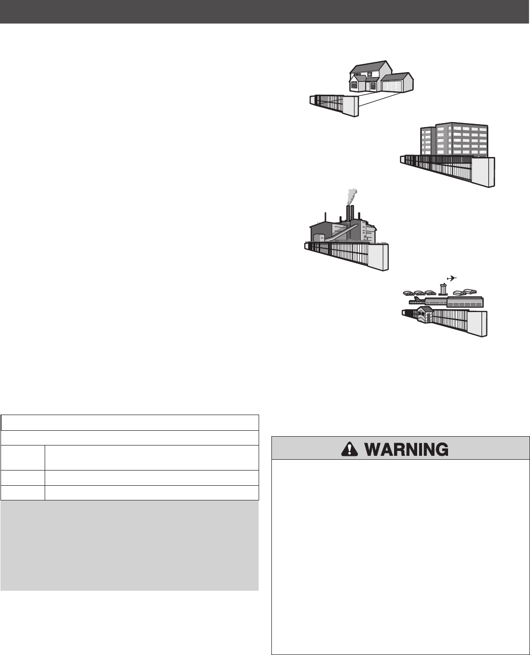
CLASS I – RESIDENTIAL VEHICULAR GATE
OPERATOR
A vehicular gate operator (or system) intended for use in garages or
parking areas associated with a residence of one-to four single families.
CLASS II – COMMERCIAL/GENERAL ACCESS
VEHICULAR GATE OPERATOR
A vehicular gate operator (or system) intended for use in a commercial
location or building such as a multi-family housing unit (five or more
single family units), hotel, garages, retail store, or other buildings
accessible by or servicing the general public.
CLASS III – INDUSTRIAL/LIMITED ACCESS
VEHICULAR GATE OPERATOR
A vehicular gate operator (or system) intended for use in an industrial
location or building such as a factory or loading dock area or other
locations not accessible by or intended to service the general public.
CLASS IV– RESTRICTED ACCESS VEHICULAR GATE
OPERATOR
A vehicular gate operator (or system) intended for use in a guarded
industrial location or building such as an airport security area or other
restricted access locations not servicing the general public, in which
unauthorized access is prevented via supervision by security personnel.
IV
I
II
III
The same type of device shall not be used for both entrapment
protection means. Use of a single device to cover both the opening
and closing directions is in accordance with the requirement;
however, a single device is not required to cover both directions.
This operator is provided with Type A. The installer is required to
install additional entrapment protection devices in each entrapment
zone.
HORIZONTAL SLIDE AND SWING GATE OPERATOR
GATE OPERATOR ENTRAPMENT PROTECTION TYPES
Type A Inherent (built into the operator) entrapment
protection system
Type B1 Non-contact sensors such as photoelectric sensors
Type B2 Contact sensors such as edge sensors
This vehicular gate operator must be installed with at least two independent entrapment protection means as specified in the table below.
To reduce the risk of INJURY or DEATH:
• READ AND FOLLOW ALL INSTRUCTIONS.
• NEVER let children operate or play with gate controls. Keep the
remote control away from children.
• ALWAYS keep people and objects away from the gate. NO ONE
SHOULD CROSS THE PATH OF THE MOVING GATE.
• Test the gate operator monthly. The gate MUST reverse on contact
with a rigid object or reverse when an object activates the non-
contact sensors. After adjusting the force or the limit of travel,
retest the gate operator. Failure to adjust and retest the gate
operator properly can increase the risk of INJURY or DEATH.
• Use the emergency release ONLY when the gate is not moving.
• KEEP GATES PROPERLY MAINTAINED. Read the owner’s manual.
Have a qualified service person make repairs to gate hardware.
• The entrance is for vehicles ONLY. Pedestrians MUST use separate
entrance.
• SAVE THESE INSTRUCTIONS.
IMPORTANT SAFETY INFORMATION

3
SAFETY INSTALLATION INFORMATION
SAFETY
1. Vehicular gate systems provide convenience and security. Gate
systems are comprised of many component parts. The gate
operator is only one component. Each gate system is specifically
designed for an individual application.
2. Gate operating system designers, installers and users must take
into account the possible hazards associated with each individual
application. Improperly designed, installed or maintained systems
can create risks for the user as well as the bystander. Gate systems
design and installation must reduce public exposure to potential
hazards.
3. A gate operator can create high levels of force in its function as a
component part of a gate system. Therefore, safety features must
be incorporated into every design. Specific safety features include:
• Edges Sensors (contact) • Guards for Exposed Rollers
• Photoelectric Sensors • Screen Mesh
• Vertical Posts • Instructional and Precautionary Signage
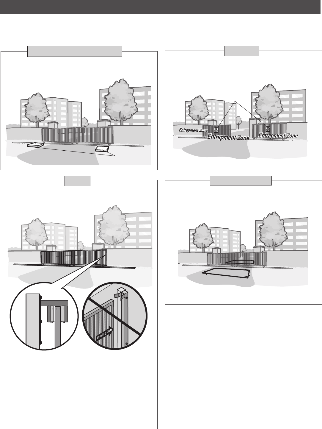
4. Install the gate operator only when:
a. The operator is appropriate for the construction and the usage
class of the gate.
b. All openings of a horizontal slide gate are guarded or screened
from the bottom of the gate to a minimum of 6 feet (1.8 m)
above the ground to prevent a 2-1/4 inches (6 cm) diameter
sphere from passing through the openings anywhere in the gate,
and in that portion of the adjacent fence that the gate covers in
the open position.
c. All exposed pinch points are eliminated or guarded, and guarding
is supplied for exposed rollers.
5. The operator is intended for installation only on gates used for
vehicles. Pedestrians must be supplied with a separate access
opening. The pedestrian access opening shall be designed to
promote pedestrian usage. Locate the gate such that persons will
not come in contact with the vehicular gate during the entire path of
travel of the vehicular gate.
6. The gate must be installed in a location so that enough clearance is
supplied between the gate and adjacent structures when opening
and closing to reduce the risk of entrapment. Swinging gates shall
not open into public access areas.
7. The gate must be properly installed and work freely in both
directions prior to the installation of the gate operator.
8. Controls intended for user activation must be located at least 6 feet
(1.8 m) away from any moving part of the gate and where the user
is prevented from reaching over, under, around or through the gate
to operate the controls. Outdoor or easily accessible controls shall
have a security feature to prevent unauthorized use.
Exception: Emergency access controls only accessible by authorized
personnel (e.g. fire, police) may be placed at any location in the
line-of-sight of the gate.
9. The Stop and/or Reset (if provided separately) must be located in
the line-of-sight of the gate. Activation of the reset control shall not
cause the operator to start.
10. A minimum of two (2) WARNING SIGNS shall be installed, one on
each side of the gate where easily visible.
11. For a gate operator utilizing a non-contact sensor:
a. Reference owner’s manual regarding placement of non-contact
sensor for each type of application. See
Install Entrapment
Protection
section.
b. Care shall be exercised to reduce the risk of nuisance tripping,
such as when a vehicle trips the sensor while the gate is still
moving.
c. One or more non-contact sensors shall be located where the risk
of entrapment or obstruction exists, such as the perimeter
reachable by a moving gate or barrier.
12. For a gate operator utilizing a contact sensor such as an edge
sensor:
a. One or more contact sensors shall be located where the risk of
entrapment or obstruction exists, such as at the leading edge,
trailing edge and post mounted both inside and outside of a
vehicular horizontal slide gate.
b. A hard wired contact sensor shall be located and its wiring
arranged so the communication between the sensor and the gate
operator is not subject to mechanical damage.
c. A wireless device such as one that transmits radio frequency (RF)
signals to the gate operator for entrapment protection functions
shall be located where the transmission of the signals are not
obstructed or impeded by building structures, natural
landscaping or similar obstruction. A wireless device shall
function under the intended end-use conditions.
d. One or more contact sensors shall be located on the inside and
outside leading edge of a swing gate. Additionally, if the bottom
edge of a swing gate is greater than 6 inches (152 mm) above
the ground at any point in its arc of travel, one or more contact
sensors shall be located on the bottom edge.
e. One or more contact sensors shall be located at the bottom edge
of a vertical barrier (arm).

4
GATE CONSTRUCTION INFORMATION
SAFETY
1. GENERAL REQUIREMENTS
1.1 Gates shall be constructed in accordance with the provisions
given for the appropriate gate type listed, refer to ASTM F2200 for
additional gate types.
1.2 Gates shall be designed, constructed and installed to not fall over
more than 45 degrees from the vertical plane, when a gate is
detached from the supporting hardware.
1.3 Gates shall have smooth bottom edges, with vertical bottom
edged protrusions not exceeding 0.50 inches (12.7 mm) when
other than the exceptions listed in ASTM F2200.
1.4 The minimum height for barbed tape shall not be less than 8 feet
(2.44 m) above grade and for barbed wire shall not be less than 6
feet (1.83 m) above grade.
1.5 An existing gate latch shall be disabled when a manually operated
gate is retrofitted with a powered gate operator.
1.6 A gate latch shall not be installed on an automatically operated
gate.
1.7 Protrusions shall not be permitted on any gate, refer to ASTM
F2200 for Exceptions.
1.8 Gates shall be designed, constructed and installed such that their
movement shall not be initiated by gravity when an automatic
operator is disconnected, in accordance with the following.
1.8.1 Vehicular horizontal slide gate. Shall not result in continuous,
unimpeded movement in either lineal direction of its travel.
1.8.2 Vehicular horizontal swing gate. Shall not result in continuous,
unimpeded movement in either direction along the arc of its path
of travel.
1.9 For pedestrian access in the vicinity of an automated vehicular
gate, a separate pedestrian gate shall be provided. The pedestrian
gate shall be installed in a location such that a pedestrian shall
not come in contact with a moving vehicular access gate. A
pedestrian gate shall not be incorporated into an automated
vehicular gate panel.
2. SPECIFIC APPLICATIONS
2.1 Any non-automated gate that is to be automated shall be
upgraded to conform to the provisions of this specification.
2.2 This specification shall not apply to gates generally used for
pedestrian access and to vehicular gates not to be automated.
2.3 Any existing automated gate, when the operator requires
replacement, shall be upgraded to conform to the provisions of
this specification in effect at that time.
3. VEHICULAR HORIZONTAL SLIDE GATES
3.1 The following provisions shall apply to Class I, Class II and Class
III vehicular horizontal slide gates:
3.1.1 All weight bearing exposed rollers 8 feet (2.44 m), or less, above
grade shall be guarded or covered.
Vehicular gates should be installed in accordance with ASTM F2200: Standard Specification for Automated Vehicular Gate Construction. For a copy,
contact ASTM directly at 610-832-9585 or www.astm.org.
3.1.2 All openings shall be designed, guarded, or screened from the
bottom of the gate to the top of the gate or a minimum of 72 in.
(1.83 m) above grade, whichever is less, to prevent a 2 1⁄4 in.
(57 mm) diameter sphere from passing through the openings
anywhere in the gate, and in that portion of the adjacent fence
that the gate covers in the open position. The gate panel shall
include the entire section of the moving gate,including any back
frame or counterbalance portion of the gate.
3.1.3 A gap, measured in the horizontal plane parallel to the roadway,
between a fixed stationary object nearest the roadway, (such as a
gate support post) and the gate frame when the gate is in either
the fully open position or the fully closed position, shall not
exceed 2 1/4 inches (57 mm), refer to ASTM F2200 for Exception.
3.1.4 Positive stops shall be required to limit travel to the designed fully
open and fully closed positions. These stops shall be installed at
either the top of the gate, or at the bottom of the gate where such
stops shall horizontally or vertically project no more than is
required to perform their intended function.
3.1.5 All gates shall be designed with sufficient lateral stability to
assure that the gate will enter a receiver guide, refer to ASTM
F2200 for panel types.
3.2 The following provisions shall apply to Class IV vehicular
horizontal slide gates:
3.2.1 All weight bearing exposed rollers 8 feet (2.44 m), or less, above
grade shall be guarded or covered.
3.2.2 Positive stops shall be required to limit travel to the designed fully
open and fully closed positions. These stops shall be installed at
either the top of the gate, or at the bottom of the gate where such
stops shall horizontally or vertically project no more than is
required to perform their intended function.
4. VEHICULAR HORIZONTAL SWING GATES
4.1 The following provisions shall apply to Class I, Class II and Class
III vehicular horizontal swing gates:
4.1.1 Gates shall be designed, constructed and installed so as not to
create an entrapment area between the gate and the supporting
structure or other fixed object when the gate moves toward the
fully open position, subject to the provisions in 4.1.1.1 and
4.1.1.2.
4.1.1.1 The width of an object (such as a wall, pillar or column) covered
by a swing gate when in the open position shall not exceed 4
inches (102 mm), measured from the center line of the pivot
point of the gate, refer to ASTM F2200 for exception.
4.1.1.2 Except for the zone specified in Section 4.1.1.1, the distance
between a fixed object such as a wall, pillar or column, and a
swing gate when in the open position shall not be less than 16
inches (406 mm), refer to ASTM F2200 for exception.
4.2 Class IV vehicular horizontal swing gates shall be designed,
constructed and installed in accordance with security related
parameters specific to the application in question.
5
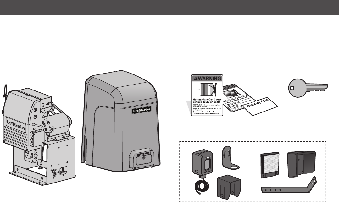
Operator
Cover
Key (2)
Warning Signs (2) and Warranty Card
CARTON INVENTORY
NOT SHOWN: Documentation Packet, Chain #41 - 30 feet, Eye Bolt Kit
INTRODUCTION
TOOLS NEEDED
• 1/2" wrench for cover screw 5/16"
• 3/4" wrench for 1/2" concrete anchors
• Screwdrivers (phillips head and flat head)
• Cable cutters and strippers
LiftMaster Monitored Retro-Reflective Photoelectric Sensor
6
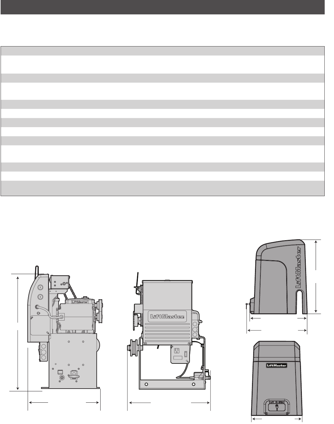
OPERATOR SPECIFICATIONS
This model is intended for use in vehicular slide gate applications:
INTRODUCTION
15.1" (38.4 cm)
Usage Classification Class I, II, III, & IV
Main AC Supply
Model SL3000501U 1/2 HP:
120 Vac, 6 Amps (12 Amps including accessory outlets)
Model SL3000101U 1 HP:
120 Vac, 12 Amps (18 Amps including accessory outlets)
Accessory Power 24 Vac, 500 mA max. for ON + SW (switched)
Maximum Gate Weight
Model SL3000501U 1/2 HP:
1000 lbs. (453.6 kg)
Model SL3000101U 1 HP:
2000 lbs. (907.2 kg)
Minimum Gate Travel Distance 4 feet (1.2 m)
Maximum Gate Travel Distance 52 feet (15.85 m)
Maximum Gate Travel Speed 1 foot/second
Maximum Daily Cycle Rate Continuous
Maximum Duty Cycle Continuous
Operating Temperature Without Heater: -20°C to 60°C (-4°F to 140°F)
With Optional Heater: -40°C to 60°C (-40°F to 140°F)
Expansion Board Provided
Inherent Entrapment Protection (Type A) RPM
External Entrapment Protection (Type B1 and/or
Type B2)
3 inputs per board - any combination of up to 3 photoelectric sensors and up to 2 edge sensors
18.3" (46.5 cm)
24" (61 cm)
18.1" (46 cm)
21.6" (54.9 cm)
21.5" (52.1 cm)
26.5"
(67.3 cm)
7
Gate must be constructed and installed according to ASTM F2200
standards (refer to page 4). Gate must fit specifications of operator
(refer to specifications).
GATE
Install catch rollers with safety
covers on the side of a post or
wall with a minimal distance of
half an inch between the rollers
and gate.
DO NOT use a gate catch post.
Because the coasting distance
may vary due to changes in
temperature, it is NOT
recommended to install a stop
or catch post in front of the
gate's path. To do so will cause
the gate to hit the post in certain
instances.
SAFETY CATCH ROLLERS
SITE PREPARATION
Check the national and local building codes BEFORE installation.
INTRODUCTION
Conduit must be UL approved for low and high voltage. Consider
the operator placement BEFORE installing the pad or post.
Concrete Pads
CONDUIT & CONCRETE PAD
Entrapment protection devices are required to protect against any
entrapment or safety conditions encountered in your gate
application. Install warning signs on both sides of the gate.
Warning Signs
SAFETY
VEHICLE LOOPS
The vehicle loops allow the gate to stay open when vehicles are
obstructing the gate path. Suggested for vehicles 14 feet (4.27 m)
or longer. Vehicle loops are not required but are recommended.
(Inside Property)
8
INTRODUCTION
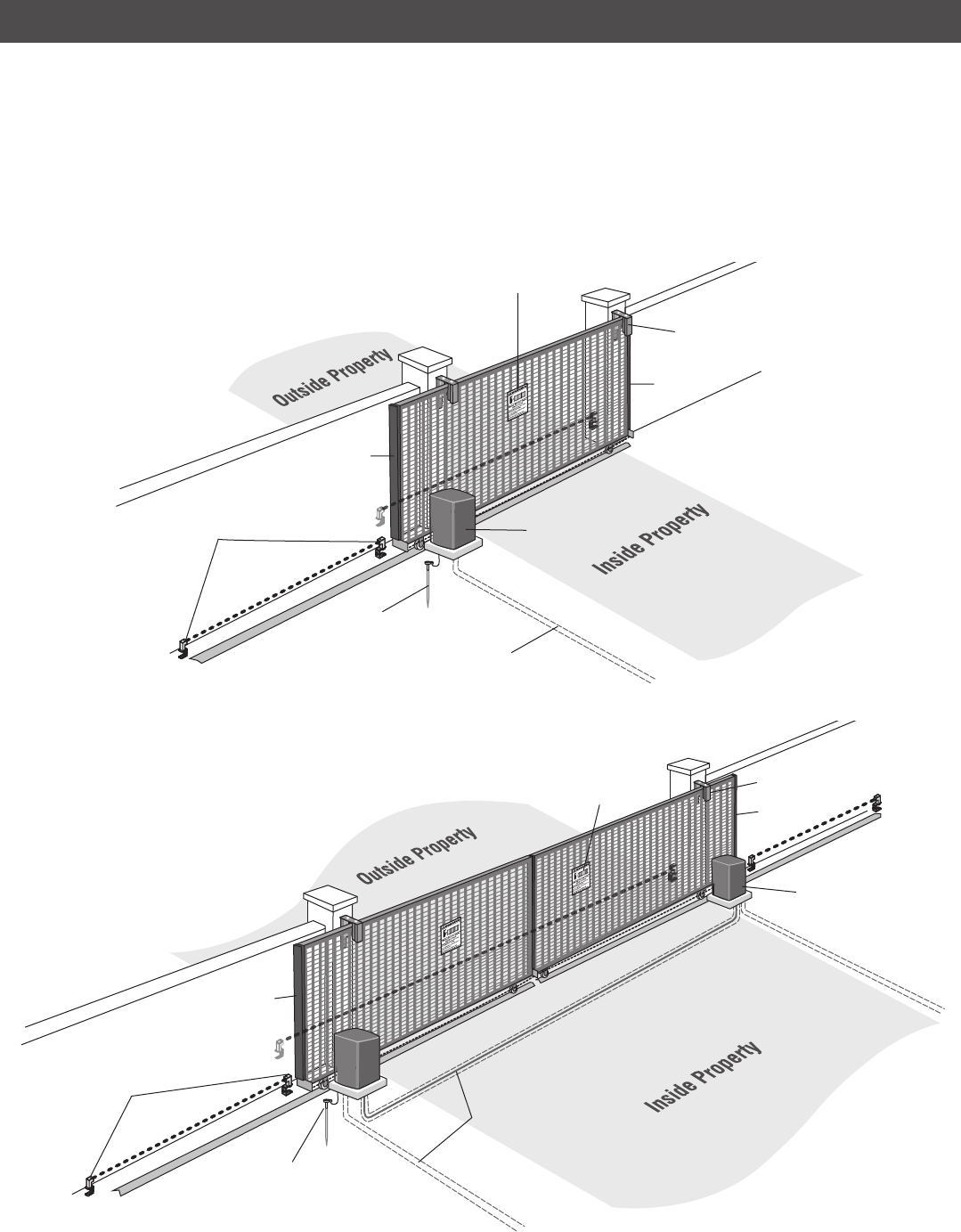
OVERVIEW OF TYPICAL INSTALLATION
IMPORTANT SAFETY INFORMATION: One or more external monitored entrapment protection sensors shall be located where the risk of entrapment or
obstruction exists at either the opening or closing direction. Any gap larger than 2-1/4 inches between the gate and a fixed object such as a wall, pillar,
column, or operator must be filled.
SINGLE GATE
DUAL GATE
Operator
Water Tight Conduit
(Not provided)
NOTE: Power and control wiring
MUST be run in separate conduits.
Earth Ground Rod
Check national and local
codes for proper depth
Warning Sign
Photoelectric
Sensors
Safety Catch
Roller
Operator
Water Tight Conduit
(Not provided)
NOTE: Power and
control wiring MUST be
run in separate
conduits.
Earth Ground Rod
Check national and local
codes for proper depth
Warning Sign
Photoelectric
Sensors
Safety Catch Roller
Edge Sensor
Edge Sensor
Edge Sensor
Edge Sensor
9
INSTALLATION
• To AVOID damaging gas, power or other underground utility lines,
contact underground utility locating companies BEFORE digging
more than 18 inches (46 cm) deep.
• DO NOT touch the heater when switch is on, heater may be hot.
(Inside Property) (Inside Property)
Gate Rail Stop
Gate Rail Stop
Gate Rail Stop
Gate Rail Stop
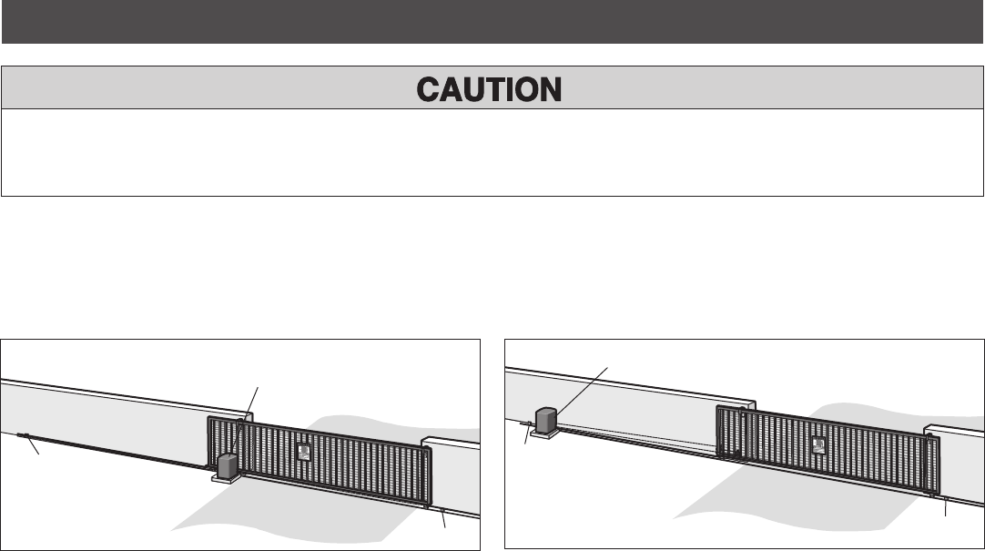
TYPES OF INSTALLATIONS
STANDARD INSTALLATION REAR INSTALLATION
Operator
Operator
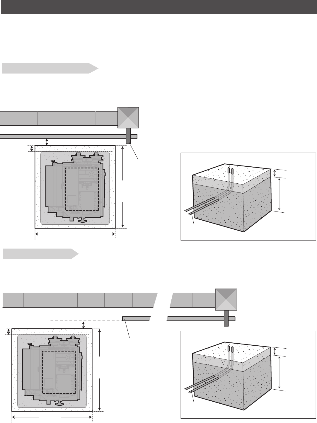
10
INSTALLATION
1/2" (1.8 cm)
24" (61 cm)
STEP 1
DETERMINE LOCATION FOR CONCRETE PAD AND OPERATOR
Check the national and local building codes before installation.
1" - 2" (2.5 - 5.1 cm)
(conduit location)
Front gate roller
REAR INSTALLATION
1. The gate operator should be installed near the back of the gate in the OPEN position. Lay out the concrete pad.
2. Install the electrical conduit.
3. Pour a concrete pad (reinforced concrete is recommended).
(Gate)
(Gate in open position)
Back of gate
1/2" (1.8 cm)
24" (61 cm)
1"-2" (2.5-5.1 cm)
(conduit location)
(Pad)
(Pad)
Below the frost
line. Check all
national and local
codes.
6" Above Ground
(conduit)
Below the frost
line. Check all
national and local
codes.
6" Above Ground
(conduit)
STANDARD INSTALLATION
1. The gate operator should be installed near the front roller of the gate. Lay out the concrete pad.
2. Install the electrical conduit.
3. Pour a concrete pad (reinforced concrete is recommended).
24" (61 cm)
24" (61 cm)