Chamberlain Group The 6761 Gate Operator Ebox Assembly User Manual

Chamberlain Group Inc, The Gate Operator Ebox Assembly

User Manual SL3000 English Manual for FCC 01-37920 Pt2
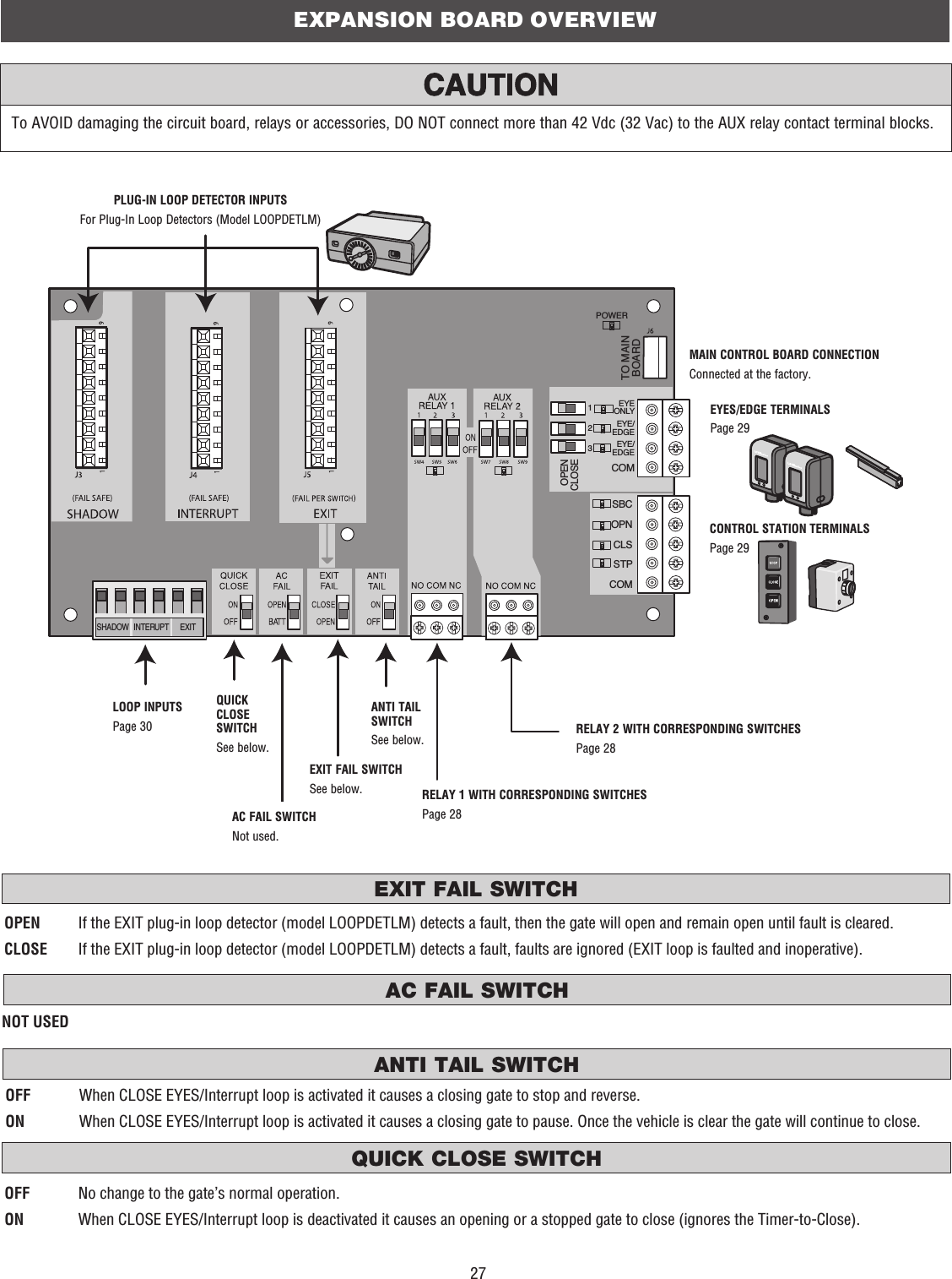
23BIPART DELAYTIMER-TO-CLOSE (TTC) LEARN BUTTONDIAGNOSTIC DISPLAYCONTROL BOARD OVERVIEWThe diagnostic display will show the operator type, firmware version, and codes. The operator type will display as “SL” followed by a “30” which indicates the operator type as SL3000U. The firmware version will show after the operator type, example “1.2”. For more information about the codes refer to the Troubleshooting section.HANDING BUTTONSThe TTC is factory set to OFF (0). Rotate the TIMER-TO-CLOSE dial to the desired setting (0 to 180 seconds). Any radio command, single button control, or CLOSE command on the control board prior to the TTC expiring will close the gate. The TTC is reset by any signals from the open controls, loops, close edges, and close photoelectric sensors.0 seconds (OFF)  The gate will remain open until the operator receives another command from a control.1-180 seconds (ON)  The gate will automatically close after the specified time period.Used in dual gate applications where a maglock, solenoid lock, or decorative overlay would require one gate to close before the other. The BIPART DELAY is also used in applications where one gate travels a longer distance than the other.ON  The operator with the BIPART DELAY dial ON will delay from the close limit when opening and be the first to close from the open limit.OFF  No affect.BIPARTDELAY2468The handing buttons are used to determine which direction the gate will open and they are also used to set the limits (refer to the Adjustment section).OPEN RIGHT   If the operator is installed on the right side of the drive when looking out of the property, a swing gate will swing to the right (turn counter clockwise) when opening and a slide gate will slide to the right when opening. OPEN LEFT   If the operator is mounted on the left side of the drive when looking out of the property, a swing gate will swing to the left (turn clockwise) when opening and a slide gate will slide to the left when opening. NOTE: For gates installed on the outside of the property, the setting will be opposite. Determine the direction by looking towards the property from the outside.HANDINGOPENLEFTOPENRIGHTThe LEARN button is used for programming (refer to Programming).
24LED STATE DEFINITIONINPUT POWER OFF OFF stateON AC power availableTIMER OFF The timer is disabledON The timer is enabled1 blink/second The timer is running2 blinks/second The timer is paused8 blinks/second The timer is cancelledGATE MOVING OFF The gate is stoppedON The gate is opening or closing1 blink/second E1 (single entrapment)8 blinks/second E2 (double entrapment)ACC PWR OVLD OFF OFF stateON Accessory overload protector openedSTATUS LEDSTEST BUTTONSCONTROL BOARD OVERVIEWFORCE DIAL12345678910The force setting should be high enough that the gate will not reverse by itself nor cause nuisance interruptions, but low enough to prevent serious injury to a person. The force setting is the same for both the open and close gate directions.Settings 1-3: Fixed force settings (the force will not adjust due to gate wear or temperature changes)Settings 4-10: Automatically increase the force due to gate wear or temperature changesADJUST THE FORCE1.   Open and close the gate with the TEST BUTTONS, ensuring that the gate is stopping at the proper open and close limit positions. If the gate is not stopping at the proper limits, adjust the force dial accordingly.2.   Place a solid object between the open gate and a rigid structure. Ensure that the gate, the solid object, and the rigid structure can withstand the forces generated during this obstruction test.3.   Run the gate in the close direction. The gate should stop and reverse upon contact with the solid object. If the gate does not reverse off the solid object, reduce the force setting by turning the force control slightly counter-clockwise. The gate should have enough force to reach both the open and close limits, but MUST reverse after contact with a solid object.4.  Repeat the test for the open direction.Used to operate the gate (OPEN, STOP and CLOSE). Also used to view the code history (refer to the Troubleshooting section).
25TERMINALS FUNCTION WIRING EXAMPLEOPEN and COMM Opens a closed gate. Hard open (maintained switch overrides external safeties and resets alarm condition). If maintained, pauses Timer-to-Close at OPEN limit. Opens a closing gate and holds open an open gate (within line-of-sight).CLOSE and COMM Closes an open gate. Hard close (maintained switch overrides external safeties and resets alarm condition within line-of-sight)STOP and COMM Stops a moving gate. Hard stop (maintained switch overrides Open and Close commands and resets alarm condition). If maintained, cancels Timer-to-Close at OPEN limit. Overrides Open and Close commands (within line-of-sight).+++N.C.–TERMINALS FUNCTION WIRING EXAMPLEFIRE DEPT (-) and OPEN (+)FIRE DEPT and OPEN terminals act as a hard open. Maintained input overrides (ignores) external safeties (photoelectric sensor and edge), pauses Timer-to-Close momentary input logic as single button control and safeties remain active, re-enables Timer-to-Close.+–The Loop terminals are used for connecting loops and various control devices such as telephone entry keypads, vehicle probes, etc. Connect the accessory to the terminals based on how the accessory should function.TERMINALS FUNCTION WIRING EXAMPLEEXIT and COM This input is a soft open command (maintained switch does not override external safeties and does not reset alarm condition). Used for exit probe, telephone entry, external exit loop detector, or any device that would command the gate to open.•   Opens a closing gate and holds open an open gate, if maintained, pauses Timer-to-Close at OPEN limit.+++–––SHADOW and COM This input is used for external shadow loop detector when loop is positioned under the swing of the gate.•  Holds open gate at open limit•   Only active when the gate is at the OPEN limit, disregarded at all other times•  Pauses Timer-to-Close at OPEN limitINTERRUPT and COM This input is used for photoelectric sensors and external interrupt loop detector when loop is on the outside of the gate.•  Holds open gate at open limit•  Stops and reverses a closing gate to open limit•   Pauses Timer-to-Close at OPEN limit, activates quick close and anti-tailgate features when enabled on the expansion boardWIRE ACCESSORIES TO CONTROL BOARDLOOPSFIRE DEPARTMENTTHREE BUTTON CONTROL STATION
26MAGLOCK WIRINGTERMINALS FUNCTION WIRING EXAMPLENC and COM Normally Closed (N.C.) output for maglocks. Relay activates prior to motor activation and during motor run. Relay is off when motor is off.COLBPLYAX-+SOLENOID LOCK WIRINGNO and COM Normally Open (N.O.) output for solenoid locks. Relay activates prior to motor activation and during motor run. Relay is off when motor is off.COLBPLYAX-+The EYES/EDGE terminals are used for connecting entrapment protection devices. At least one external monitored entrapment protection device is required prior to gate movement. Monitored entrapment protection devices should have been installed with the operator at the time of installation. Only ONE monitored device may be connected to each input. A monitored device sends a pulsed signal to the operator so the operator is aware of the device. If the operator does not receive the signal from the device indicating it is working properly, it will not run in that direction.TERMINALS FUNCTION WIRING EXAMPLECLOSE EYES/INTERRUPTThe CLOSE EYES/INTERRUPT input is for close direction photoelectric sensors. When an obstruction is sensed during gate closing the gate will open to the full open position. This input will be disregarded during gate opening and resets the Timer-to-Close.+++–––MKACLOSE EDGE The CLOSE EDGE input is for the close direction edge sensors. When an obstruction is sensed during gate closing the gate will reverse to the full open position, disengaging the Timer-to-Close. This input will be disregarded during gate opening.OPEN EYES/EDGEThe OPEN EYES/EDGE input is for open direction photoelectric sensors or edge sensors. When an obstruction is sensed during gate opening the gate will reverse for 4 seconds then stop. This input will be disregarded during gate closing.LOCKSPHOTOELECTRIC SENSORS AND EDGE SENSORSWIRE ACCESSORIES TO CONTROL BOARD
27SHADOW   INTERUPT      EXITSBCOPNCLSSTPCOMEYEONLYEYE/EDGEEYE/EDGECOM123OPENCLOSETO MAINBOARDPOWEREXPANSION BOARD OVERVIEWTo AVOID damaging the circuit board, relays or accessories, DO NOT connect more than 42 Vdc (32 Vac) to the AUX relay contact terminal blocks.PLUG-IN LOOP DETECTOR INPUTSFor Plug-In Loop Detectors (Model LOOPDETLM)MAIN CONTROL BOARD CONNECTIONConnected at the factory.LOOP INPUTSPage 30QUICK CLOSE SWITCHAC FAIL SWITCHEXIT FAIL SWITCHANTI TAIL SWITCHQUICK CLOSE SWITCHSee below.AC FAIL SWITCHNot used.EXIT FAIL SWITCHSee below.ANTI TAIL SWITCHSee below.RELAY 1 WITH CORRESPONDING SWITCHESPage 28RELAY 2 WITH CORRESPONDING SWITCHESPage 28EYES/EDGE TERMINALSPage 29CONTROL STATION TERMINALSPage 29NOT USEDOPEN  If the EXIT plug-in loop detector (model LOOPDETLM) detects a fault, then the gate will open and remain open until fault is cleared.CLOSE  If the EXIT plug-in loop detector (model LOOPDETLM) detects a fault, faults are ignored (EXIT loop is faulted and inoperative).OFF  When CLOSE EYES/Interrupt loop is activated it causes a closing gate to stop and reverse.ON  When CLOSE EYES/Interrupt loop is activated it causes a closing gate to pause. Once the vehicle is clear the gate will continue to close.OFF  No change to the gate’s normal operation.ON  When CLOSE EYES/Interrupt loop is deactivated it causes an opening or a stopped gate to close (ignores the Timer-to-Close).
28EXPANSION BOARD OVERVIEWAUXILIARY RELAY 1 AND 2RELAY SETTING SWITCH SETTINGS AUX RELAY 1 AUX RELAY 2123Off (no feature selected)OFF OFF OFF Relay always off.Open Limit Switch OFF OFF ON Energizes at open limit. Use with SAMS (Sequenced Access Management System, jointly with barrier gate).Close Limit Switch OFF ON OFF Energizes when not at close limit. For an additional audible or visual display, connect an external light (low voltage).Gate Motion OFF ON ON Energizes when motor is on (gate in motion). For an additional audible or visual display, connect an external buzzer or light (low voltage).Pre-Motion Delay ON OFF OFF Energizes 3 seconds before gate motion and remains energized during gate motion. The onboard alarm will sound. For an additional audible or visual display, connect an external buzzer or light (low voltage).Energizes 3 seconds before gate motion and remains energized during gate motion. For an additional audible or visual display, connect an external buzzer or light (low voltage).Power ON ON OFF Not used.Tamper ON OFF ON Energizes if gate is manually tampered with by being pushed off of close limit. For an additional audible or visual display, connect an external buzzer or light (low voltage).Cycle Quantity Feedback*ON ON ON The 1, 2, and 3 LEDs will blink out the cycle count (cycle count is stored on the control board). See below.Not used.SHADOW   INTERUPT      EXITSBCOPNCLSSTPCOMCOMOPENCLOSEAUX RELAY 1 AUX RELAY 2AUX Relay 2 N.C.ComAUX Relay 2 N.O.AUX Relay 1 N.C.ComAUX Relay 1 N.O.+–Traffic LightClass 2 Power Source(42 Vdc [34 Vac], 5 A maximum)Normally Open (N.O.) and Normally Closed (N.C.) relay contacts to control external devices, for connection of Class 2, low voltage (42 Vdc [34 Vac] max 5 Amps) power sources only. Function of relay contact activation determined by switch settings.CYCLE COUNT*  First, note the current Aux Relay switch positions. To determine the actual cycles that the gate operator has run (in thousands), set all three Aux Relay switches to the ON setting for Aux Relay 1. The Expansion Board’s 1, 2, and 3 LEDs will blink out the cycle count, with 1 LED blinking 1000’s, 2 LED blinking 10,000’s, 3 LED blinking 100,000’s, and simultaneously all three LED’s blink 1,000,000’s (e.g. 1 LED blinks 3 times, 2 LED blinks 6 times, and 3 LED blinks once. Cycle count is 163,000.). Cycle count displayed is between 1,000 and 9,999,000 cycles. After servicing, set Aux Relay switches back to their appropriate positions. Cycle count cannot be reset or changed. If under 1,000 cycles the 1, 2, and 3 LEDs will turn on for 10 seconds, then turn off.NOTE: The expansion board will flash the cycle count 3 times then all the LEDs will turn on solid for 10 seconds then turn off.AUXILIARY RELAY WIRING EXAMPLERED/GREEN LIGHT FUNCTIONALITYRed light wired to AUX RELAY 1. Green light wired to AUX RELAY 2.GATE STATE AUX RELAY 1 SWITCHES AUX RELAY 2 SWITCHES1 OFF 2 OFF 3 OFF 1 ON 2 ON 3 ONClosed Red light OFF*  Green light OFFOpening Red light ON/Flash Green light OFFOpen Red light OFF Green light ONClosing Red light ON/Flash Green light OFFDefined Mid Stop n/a n/aUndefined Mid Stop Red light ON Green light OFFTimer more than 5 seconds Red light OFF Green light ONTimer less than 5 seconds Red light ON/Flash Green light OFF* For red light ON when gate is closed, set switch 1 on AUX RELAY 1 to ON
29TERMINALS FUNCTIONALITY WIRING EXAMPLESBC and COM •  Gate command sequence - Open, Stop, Close, Stop, ...•   Soft Open ,Soft Close, Soft Stop (maintained switch does not override external safeties and does not reset alarm condition)OPEN and COM •  Open command - opens a closed gate•   Soft open (maintained switch does not override external safeties and does not reset alarm condition)•  If maintained, pauses Timer-to-Close at OPEN limit•  Opens a closing gate and holds open an open gateCLOSE and COM •  Close command - closes an open gate•   Soft close (maintained switch does not override external safeties and does not reset alarm condition)STOP and COM •  Stop command - stops a moving gate•   Hard stop (maintained switch overrides Open and Close commands and resets alarm condition)•  If maintained, pauses Timer-to-Close at OPEN limit•  Overrides an Open or Close commandSBCOPNCLSSTPCOMCOMOCLOSEThe EYES/EDGE terminals are used for connecting entrapment protection devices. At least one external monitored entrapment protection device is required prior to gate movement. Monitored entrapment protection devices should have been installed with the operator at the time of installation. Only ONE monitored device may be connected to each input. A monitored device sends a pulsed signal to the operator so the operator is aware of the device. If the operator does not receive the signal from the device indicating it is working properly, it will not run in that direction.TERMINALS FUNCTIONALITY WIRING EXAMPLEEYE ONLY and COM Open or Close Direction Photoelectric Sensors, the functionality is based on the switch settings (located next to the terminals) Switch set to CLOSE: gate reverses fully when an obstruction is sensedSwitch set to OPEN: gate reverses 4 seconds when an obstruction is sensedEYE/EDGE and COM Open or Close Direction Photoelectric Sensors or Edge Sensor, the functionality is based on the switch settings (located next to the terminals) Switch set to CLOSE: gate reverses fully when an obstruction is sensedSwitch set to OPEN: gate reverses 4 seconds when an obstruction is sensedEYE/EDGE and COM Open or Close Direction Photoelectric Sensors or Edge Sensor, the functionality is based on the switch settings (located next to the terminals) Switch set to CLOSE: gate reverses fully when an obstruction is sensedSwitch set to OPEN: gate reverses 4 seconds when an obstruction is sensedSBCEYEONLYEYE/EDGEEYE/EDGECOM123OPENCLOSETSBCEYEONLYEYE/EDGEEYE/EDGECOM123OPENCLOSESBCEYEONLYEYE/EDGEEYE/EDGECOM123OPENCLOSETWIRE ACCESSORIES TO EXPANSION BOARDCONTROL STATIONPHOTOELECTRIC SENSORS AND EDGE SENSORS
30INPUTS FUNCTIONALITY WIRING EXAMPLEEXIT Loop wire connection for plug-in loop detector when loop is inside secured area near gate.•  Open command - opens a closed gate•   Soft open (maintained switch does not override external safeties and does not reset alarm condition)•  If maintained, pauses Timer-to-Close at OPEN limit•  Opens a closing gate and holds open an open gateSHADOW Loop wire connection for plug-in loop detector when loop is positioned under the gate.•  Holds open gate at open limit•  Disregarded during gate motion •  Pauses Timer-to-Close at Open LimitINTERRUPT Loop wire connection for plug-in loop detector when loop is on the outside of the gate.•  Holds open gate at open limit•  Stops and reverses a closing gate•  Pauses Timer-to-Close at Open LimitSHADOW   INTERUPT      EXITExit LoopInterrupt LoopShadow LoopWIRE ACCESSORIES TO EXPANSION BOARDLOOPSSAMS WIRING WITH RELAYS NOT ENERGIZEDADDITIONAL WIRINGCOMMLINKBABIPARTDELAY2468HANDINGOPENLEFTOPENRIGHTANTENNA CURRENT SENSORMOTOR DRIVE RPM & LIMITS ALARM EXP.BOARD24 VAC INCLASS 2 SUPPLY24 VAC500 mA MAXID RESETGNDSHADOW   INTERUPT      EXITSBCOPNCLSSTPCOMEYEONLYEYE/EDGEEYE/EDGECOM123OPENCLOSEDEVICE INPUTSTO MAINBOARDPOWERAccess DeviceExit InputShadow InputAUX Relay 1CNOAuxiliary CommandDipswitch settings for AUX Relay 1: 1-OFF, 2-OFF, 3-ONControl BoardExpansion BoardBarrier Arm Operator
31N.O.COMN.C.N.O.COMN.C.–+++–++++SHADOW   INTERUPT      EXITSBCOPNCLSSTPCOMEYEONLYEYE/EDGEEYE/EDGECOM123OPENCLOSETO MAINBOARDPOWERN.C.N.O.COM–++++++++++–––––––COMMLINKBABIPARTDELAY2468HANDINGOPENLEFTOPENRIGHTANTENNA CURRENT SENSORMOTOR DRIVE RPM & LIMITS ALARM EXP.BOARD24 VAC INCLASS 2 SUPPLY24 VAC500 mA MAXID RESETGND  Maglock (Optional)Solenoid Lock (Optional)ORShielded Twisted Pair Cable (Primary/Secondary link to other gate operator) Ground the shield of the cable to the chassis ground of each operator.ACCESSORY POWER24 Vac 500 mA Maximum(Not Provided)(Not Provided)N.C.INTERRUPT LOOP or PHOTOELECTRIC SENSORS for CLOSE cycleEDGE SENSOR for CLOSE cycleEDGE SENSOR or PHOTOELECTRIC SENSORS for OPEN cycleSHADOW LOOPEXIT LOOPFIRE DEPARTMENT3-BUTTON CONTROL STATIONCONTROL BOARDHEATERSHADOW LOOPEXIT LOOPINTERRUPT LOOPAUXILIARY RELAY 2AUXILIARY RELAY 1SINGLE BUTTON CONTROL STATION3-BUTTON CONTROL STATIONPHOTOELECTRIC SENSORSPHOTOELECTRIC SENSORS or EDGE SENSORSNOTE: These switches determine if the corresponding photoelectric sensor or edge sensor will function for the OPEN or CLOSE cycle.PLUG-IN LOOP DETECTORModel LOOPDETLMNOTE: These switches control how the Auxiliary Relays will function.EXPANSION BOARDJUNCTION BOXLNGNDIncoming PowerN.C.To protect against fire and electrocution:•   DISCONNECT power BEFORE installing or servicing operator.For continued protection against fire:•  Replace ONLY with fuse of same type and rating.ADDITIONAL WIRINGFIELD WIRING
32PROGRAMMING REMOTE CONTROLS (NOT PROVIDED)OPTION DESCRIPTION PROGRAMMING STEPSSingle button as OPEN onlyProgram a single button on the remote control for open only. The Timer-to-Close can be set to close the gate.1.   Press and release the LEARN button (operator will beep and green XMITTER LED will light). NOTE: The operator will time out of programming mode after 30 seconds.2.  Press the OPEN button.3.   Press the remote control button that you would like to program. Single button (SBC) as OPEN, CLOSE, and STOPProgram one remote control button as an open, close, and stop. 1.   Press and release the LEARN button (operator will beep and green XMITTER LED will light). NOTE: The operator will time out of programming mode after 30 seconds.2.   Press the remote control button that you would like to program. Three separate buttons as OPEN, CLOSE, and STOPProgram each remote control button as an open, close, and stop. 1.   Press and release the LEARN button (operator will beep and green XMITTER LED will light). NOTE: The operator will time out of programming mode after 30 seconds.2.   Press the OPEN, CLOSE, or STOP button, depending on the desired function.3.   Press the remote control button that you would like to program. NOTICE: This device complies with part 15 of the FCC rules and Industry Canada (IC) licence-exempt RSS standard(s). Operation is subject to the following two conditions: (1) this device may not cause harmful interference, and (2) this device must accept any interference received, including interference that may cause undesired operation.Any changes or modifications not expressly approved by the party responsible for compliance could void the user’s authority to operate the equipment.This Class B digital apparatus complies with Canadian ICES-003.This device has been tested and found to comply with the limits for a Class B digital device, pursuant to part 15 of the FCC rules. These limits are designed to provide reasonable protection against harmful interference in a residential installation. This equipment generates, uses and can radiate radio frequency energy and, if not installed and used in accordance with the instructions, may cause harmful interference to radio communications. However, there is no guarantee that interference will not occur in a particular installation. If this equipment does cause harmful interference to radio or television reception, which can be determined by turning the equipment off and on, the user is encouraged to try to correct the interference by one or more of the following measures:- Reorient or relocate the receiving antenna.- Increase the separation between the equipment and receiver.- Connect the equipment into an outlet on a circuit different from that to which the receiver is connected.- Consult the dealer or an experienced radio/TV technician for help.A total of 50 Security+ 2.0™ remote controls and 2 keyless entries (1 PIN for each keyless entry) can be programmed to the operator. When programming a third keyless entry to the operator, the first keyless entry will be erased to allow the third keyless entry to be programmed. When the operator’s memory is full it will exit the programming mode and the remote control will not be programmed. The memory will need to be erased before programming any additional remote controls. NOTE: If installing an 86LM to extend the range of the remote controls DO NOT straighten the antenna.There are 3 different options for programming the remote control depending on how you would like the remote control to function. Choose a programming option:The operator will automatically exit learn mode (operator will beep and green XMITTER LED will go out) if programming is successful. To program additional Security+ 2.0™ remote controls or remote control buttons, repeat the programming steps above.Once the remote control has been programmed the operator will operate as follows:When gate is in the closed position, activation of the remote control button will open the gate. During the open cycle another activation of the remote control will stop the gate and the next activation of the remote control will close the gate. When the gate is in the open position, activation of the remote control button will close the gate. If the remote control is activated while the gate is closing, the gate will stop and the next activation will open the gate.
33PROGRAMMINGERASE ALL CODESTO REMOVE AND ERASE ALL MONITORED ENTRAPMENT PROTECTION DEVICESLIFTMASTER INTERNET GATEWAY (NOT PROVIDED)Program using the learn button on the operator's control board: Program using the reset button on the operator:1.   Connect the ethernet cable to the LiftMaster Internet Gateway and the router.2.   Connect power to the LiftMaster Internet Gateway.3.   Create an online account by visiting www.myliftmaster.com.4.   Register the LiftMaster Internet Gateway.5.   Use an internet enabled computer or smartphone to add devices. The LiftMaster Internet Gateway will stay in learn mode for three minutes.6.   Press the Learn button twice on the primary operator (the operator will beep as it enters learn mode). The LiftMaster Internet Gateway will pair to the operator if it is within range and the operator will beep if programming is successful.1.   Connect the ethernet cable to the LiftMaster Internet Gateway and the router.2.   Connect power to the LiftMaster Internet Gateway.3.   Create an online account by visiting www.myliftmaster.com.4.   Register the LiftMaster Internet Gateway.5.   Use an internet enabled computer or smartphone to add devices. The LiftMaster Internet Gateway will stay in learn mode for three minutes.6.   Ensure gate is closed.7.   Give the operator an OPEN command.8.   Within 30 seconds, when the gate is at the open limit press and release the reset button 3 times (on primary gate) to put primary operator into High Band Learn Mode (the operator will beep as it enters learn mode). The LiftMaster Internet Gateway will pair to the operator if it is within range and the operator will beep if programming is successful.To program the operator to the LiftMaster Internet Gateway:The status as shown by the LiftMaster Internet Gateway app will be either “open” or “closed”. The gate operator can then be controlled through the LiftMaster Internet Gateway app.1.   Press and release the LEARN button (operator will beep and green XMITTER LED will light).2.   Press and hold the LEARN button again until the green XMITTER LED flashes and then release the button (approximately 6 seconds). All remote control codes are now erased.1.   Remove the entrapment protection device wires from the terminal block.2.   Press and release the OPEN LEFT and OPEN RIGHT buttons simultaneously. The handing direction LED will remain solid. The other direction LED will begin flashing (entering setup mode).3.   Press the OPEN LEFT and OPEN RIGHT buttons simultaneously to exit.
34SETTINGSGATE OPERATOR SETUP EXAMPLESSetting RESIDENTIAL COMMERCIAL/GENERAL ACCESSCOMMERCIAL INDUSTRIALQuick Close switch settingNormally set to OFF. Normal gate close (timer or control).Normally set to OFF. Normal gate close (timer or control).Normally set to OFF. Normal gate close (timer or control).Set to ON, so that gate closes immediately after vehicle passes CLOSE EYES/Interrupt loop.Anti-Tail switch setting Normally set to OFF. CLOSE EYES/Interrupt loop reverses a closing gate.Normally set to OFF. CLOSE EYES/Interrupt loop reverses a closing gate.Set to ON. In attempt to prevent vehicle tail-gating, CLOSE EYES/Interrupt loop pauses a closing gate.Set to ON. In attempt to prevent vehicle tail-gating, CLOSE EYES/Interrupt loop pauses a closing gate.Bipart Delay switch settingFor DUAL-GATE site, set to ON for gate that delays upon opening.For DUAL-GATE site, set to ON for gate that delays upon opening.For DUAL-GATE site, set to ON for gate that delays upon opening.For DUAL-GATE site, set to ON for gate that delays upon opening.Aux Relay Out – Open Limit SwitchTypically not required. Use with SAMS (Sequence Access Management System).1)  Use with SAMS (Sequence Access Management System).2)  Connect “Gate Open” indicator (e.g. light).1)  Use with SAMS (Sequence Access Management System).2)  Connect “Gate Open” indicator (e.g. light).Aux Relay Out – Close Limit SwitchTypically not required. Typically not required. Connect “Gate Close/Secure” indicator (e.g. light).Connect “Gate Close/Secure” indicator (e.g. light).Aux Relay Out – Gate MotionAttach alert signal (audible or visual alert system).Attach alert signal (audible or visual alert system).Attach alert signal (audible or visual alert system).Attach alert signal (audible or visual alert system).Aux Relay Out – Pre-Motion DelayAttach alert signal (audible or visual alert system).Attach alert signal (audible or visual alert system).Attach alert signal (audible or visual alert system).Attach alert signal (audible or visual alert system).Aux Relay Out – Tamper(Slide Gates Only)Attach alert signal (audible or visual alert system) to indicate if gate is manually tampered with by being pushed off of close limit.Attach alert signal (audible or visual alert system) to indicate if gate is manually tampered with by being pushed off of close limit.Attach alert signal (audible or visual alert system) to indicate if gate is manually tampered with by being pushed off of close limit.Attach alert signal (audible or visual alert system) to indicate if gate is manually tampered with by being pushed off of close limit.Cycle Quantity Feedback Use during servicing only to determine operator cycles.Use during servicing only to determine operator cycles.Use during servicing only to determine operator cycles.Use during servicing only to determine operator cycles.Fire Dept Open input Typically not required. Connect emergency access system (Knox box switch, SOS system, etc.).Typically not required. Typically not required.Heater Accessory(Model HTRNB)The heater keeps the gearbox and batteries at a suitable temperature when the outside temperature is below -4°F. The thermostat MUST be set between 45°F and 60°F to ensure proper gate operation.The heater keeps the gearbox and batteries at a suitable temperature when the outside temperature is below -4°F. The thermostat MUST be set between 45°F and 60°F to ensure proper gate operation.The heater keeps the gearbox and batteries at a suitable temperature when the outside temperature is below -4°F. The thermostat MUST be set between 45°F and 60°F to ensure proper gate operation.The heater keeps the gearbox and batteries at a suitable temperature when the outside temperature is below -4°F. The thermostat MUST be set between 45°F and 60°F to ensure proper gate operation.The following are example setups for the gate operator. Your specific site requirements may be different. Always setup the operator system to the site requirements, including all necessary entrapment protection devices. RESIDENTIAL: One to four residential homes sharing a gated entrance/exit, allowing vehicle access trumps security concerns  COMMERCIAL/GENERAL ACCESS: A residential community (more than four homes) having one or more gated entrances/exits, allowing vehicle access trumps security concerns COMMERCIAL: Business site where security (gate closed) is important INDUSTRIAL: Large business site where security is required
35SETTINGSDUAL GATE SETTINGSFEATURE PRIMARY OPERATOR SECONDARY OPERATORQUICK CLOSE Switch ON OFFANTI-TAIL Switch ON OFFEXPANSION BOARDFEATURE PRIMARY OPERATOR SECONDARY OPERATORTimer-to-Close Set the TTC dial to desired setting OFFBi-Part Delay Switch Bi-Part Delay: ON (will open last and close first)Tandem Mode: OFFBi-Part Delay: OFF (will open first and close last)Tandem Mode: OFFNOTE: We recommend that all accessories and board configurations are set on the primary operator.MAIN CONTROL BOARDACCESSORY PRIMARY OPERATOR SECONDARY OPERATORRemote Controls Program remote controls 1 to 50 to the primary operator. Program remote controls 51 to 100 to the secondary operatorLiftMaster Internet GatewayProgram to primary operator.Garage and Gate MonitorProgram to primary operator.
36NOTES:•   Severe or high cycle usage will require more frequent maintenance checks.•   Limits may have to be reset after any major drive chain adjustments.•   If lubricating chain, use only lithium spray. Never use grease or silicone spray. •   Over time, the drive chain on the operator will stretch and need to be tightened. To tighten the drive chain adjust either of the two chain eye bolts. The chain should have no more than 1 inch of sag for every 10 feet of chain length.•   It is suggested that while at the site voltage readings be taken at the operator. Using a digital voltmeter, verify that the incoming voltage to the operator is within ten percent of the operator’s rating.MAINTENANCEDisconnect all power to the operator before servicing.DESCRIPTION TASKCHECK AT LEAST ONCE EVERYMONTH 6 MONTHSEntrapment Protection Devices Check and test for proper operation XWarning Signs Make sure they are present XManual Disconnect Check and test for proper operation XDrive Chain and Sprockets Check for excessive slack and lubricate XBelt and Pulley Check for excessive slack, wear or damage XGate Inspect for wear or damage XAccessories Check all for proper operation XElectrical Inspect all wire connections XChassis Mounting Bolts Check for tightness XOperator Inspect for wear or damage XMAINTENANCETo reduce the risk of SEVERE INJURY or DEATH:•   READ AND FOLLOW ALL INSTRUCTIONS.•   ANY maintenance to the operator or in the area near the operator MUST NOT be performed until disconnecting the electrical power (AC or solar and battery) and locking-out the power via the operator power switch. Upon completion of maintenance the area MUST be cleared and secured, at that time the unit may be returned to service.•   Disconnect power at the fuse box BEFORE proceeding. Operator MUST be properly grounded and connected in accordance with national and local electrical codes. NOTE: The operator should be on a separate fused line of adequate capacity.•   NEVER let children operate or play with gate controls. Keep the remote control away from children.•   ALWAYS keep people and objects away from the gate. NO ONE SHOULD CROSS THE PATH OF THE MOVING GATE.•   The entrance is for vehicles ONLY. Pedestrians MUST use separate entrance.•   Test the gate operator monthly. The gate MUST reverse on contact with a rigid object or reverse when an object activates the non-contact sensors. After adjusting the force or the limit of travel, retest the gate operator. Failure to adjust and retest the gate operator properly can increase the risk of INJURY or DEATH.•   Use the manual disconnect release ONLY when the gate is NOT moving.•   KEEP GATES PROPERLY MAINTAINED. Read the owner’s manual. Have a qualified service person make repairs to gate hardware.•   ALL maintenance MUST be performed by a LiftMaster professional.•   Activate gate ONLY when it can be seen clearly, is properly adjusted and there are no obstructions to gate travel.•   SAVE THESE INSTRUCTIONS.IMPORTANT SAFETY INFORMATIONTo protect against fire and electrocution:•   DISCONNECT power (AC or solar and battery) BEFORE installing or servicing operator.For continued protection against fire:•  Replace ONLY with fuse of same type and rating.
37TROUBLESHOOTINGDIAGNOSTIC CODESPress and hold the STOP button......then press and hold the CLOSE button...TO VIEW THE CODESThe codes will show on the diagnostic display.TO SCROLL THROUGH THE SAVED CODESPress the OPEN button to cycle to the most recent code ("01").Press the CLOSE button to cycle to the oldest code (up to "20").A SECOND LATER....The operator will only keep track of up to 20 codes, then will start saving over the oldest codes as new codes occur. The operator will show the code sequence number followed by the code number:COMMLINKBABIPARTDELAY2468HANDINGOPENLEFTOPENRIGHTANTENNA CURRENT SENSORMOTOR DRIVE RPM & LIMITS ALARM EXP.BOARD24 VAC INCLASS 2 SUPPLY24 VAC500 mA MAXID RESETGNDDIAGNOSTICS DISPLAYOPEN, CLOSE, & STOP BUTTONS...then press and hold the OPEN button until "Er" shows on the display.CODE NUMBERThe second number shown after the code sequence number is the code itself (31-99, example" "31"). Refer to the chart on the following page for an explanation of each code.CODE SEQUENCE NUMBERThe first number shown is the most recent code (example: "01"). The display will show the sequence of codes that occurred starting with "01" and going up to code "20". TO EXITPress and release the STOP button to exit. The display will also time out after two minutes of inactivity.TO RESET THE CODE HISTORY1.   Press and hold the STOP button for six seconds. The display will show "Er" then "CL" alternately for six seconds.2.   Release the STOP button. The code history has now been reset and the display will show "- -" until a new code occurs.3.  Press and release the STOP button to exit.To protect against fire and electrocution:•   DISCONNECT power (AC or solar and battery) BEFORE installing or servicing operator.For continued protection against fire:•  Replace ONLY with fuse of same type and rating.
38DIAGNOSTIC CODES continued...TROUBLESHOOTINGSome codes are saved in the code history and some are not. If a code is not saved it will briefly appear on the display as it occurs, then disappear.Code Meaning Solution Saved31 Main control board has experienced an internal failure.Disconnect all power, wait 15 seconds, then reconnect power (reboot). If issue continues, replace main control board.NO35 Max-Run-Time Exceeded Error Attempt to run and review for duration and obstructions. Max-Run-Time can be re-measured by saving one or both of the limits again.YES36Product ID Error Was the control board just replaced? If so, erase limits, enter limit setup mode and set limits. If not, disconnect all power, wait 15 seconds, then reconnect power before changing product ID harness.YES37Product ID Failure Unplug product ID harness then plug back in. Disconnect all power, wait 15 seconds, then reconnect power before replacing product ID harness.YES43 Loop Error - Failure or missing exit loop (SHORT or OPEN - LiftMaster Plug-in Loop Detector only)Check loop wiring throughout connection. May be a short in the loop, or an open connection in the loop.YES44Loop Error - Failure or missing shadow loop (SHORT or OPEN - LiftMaster Plug-in Loop Detector only)Check loop wiring throughout connection. May be a short in the loop, or an open connection in the loop.YES45Loop Error - Failure or missing interrupt loop (SHORT or OPEN - LiftMaster Plug-in Loop Detector only)Check loop wiring throughout connection. May be a short in the loop, or an open connection in the loop.YES46 Wireless edge battery low Replace batteries in wireless edge. YES47 Motor control board fault Relay fault detected in the motor control board. Replace the motor control board.YES50Run-Distance Error The limits are less than the minimum requirement or longer than what was learned. Check limit positions and proper switch function. Run-distance can be re-learned by setting the handing again.YES53Brownout occurred AC/DC board supply dipped below allowable level. Review power supply and wiring. If rebooting, ensure enough time for discharge of power to force a fresh boot.YES54Wireless Second Operator Communication Error Check the second operator for power. If OFF, restore power and try to run the system. If powered, deactivate the wireless feature and then re-learn the second operator.YES55 System AC Overvoltage Call utility. YES56 System AC Undervoltage Check wiring and wire gauge to operator. YES57 Limit Error - Stuck Switch Check switch for proper operation. Check harness for shorts. Replace if defective.YES58 Limit Error - Wrong Switch Check motor wiring. YES59 Missing Power Board Check harness for shorts. Check for presence of power board.  YES60 Minimum number of monitored entrapment protection devices (one) not installed. Review monitored entrapment protection device connections. NO61 CLOSE EYE/INTERRUPT held more than 3 minutes (main board)Check CLOSE EYE/INTERRUPT input on main board; check for alignment or obstruction.YES62 CLOSE EDGE held more than 3 minutes (main board)Check CLOSE EDGE input on main board; check for alignment or obstruction.YES63 OPEN EYE/EDGE held more than 3 minutes (main board)Check OPEN EYE/EDGE input on main board; check for alignment or obstruction.YES64 CLOSE EYE/INTERRUPT held more than 3 minutes (expansion board)Check wired input on expansion board; check for alignment or obstruction.YES65 CLOSE EYE/EDGE held more than 3 minutes (expansion board)Check wired input on expansion board; check for alignment or obstruction.YESLiftMaster System Installed System Informational External Entrapment ProtectionInherent Entrapment Protection
39DIAGNOSTIC CODES continued...TROUBLESHOOTINGSome codes are saved in the code history and some are not. If a code is not saved it will briefly appear on the display as it occurs, then disappear.Code Meaning Solution Saved66 OPEN EYE/EDGE held more than 3 minutes (expansion board)Check wired input on expansion board; check for alignment or obstruction.YES67 Wireless edge triggered more than 3 minutes Check wired input for wiring issue or obstruction. YES68 Wireless edge loss of monitoring Check wireless edge inputs. YES69 Wireless edge triggered IF an obstruction occurred, no action required. If an obstruction did NOT occur, check inputs and wiring.NO70CLOSE EYE/INTERRUPT triggered, causing reversal, preventing close, or resetting TTC (main board)IF an obstruction occurred, no action required. If an obstruction did NOT occur, check alignment, inputs, and wiring.NO71 CLOSE EDGE triggered, causing reversal, preventing close, or canceling TTC (main board)IF an obstruction occurred, no action required. If an obstruction did NOT occur, check alignment, inputs, and wiring.NO72 OPEN EYE/EDGE triggered, causing reversal or preventing opening (main board)IF an obstruction occurred, no action required. If an obstruction did NOT occur, check alignment, inputs, and wiring.NO73CLOSE EYE/INTERRUPT triggered, causing reversal, preventing close, or resetting TTC (expansion board)IF an obstruction occurred, no action required. If an obstruction did NOT occur, check alignment, inputs, and wiring.NO74CLOSE EYE/EDGE triggered, causing reversal and preventing close or canceling TTC (expansion board)IF an obstruction occurred, no action required. If an obstruction did NOT occur, check alignment, inputs, and wiring.NO75 OPEN EYE/EDGE triggered, causing reversal or preventing opening (expansion board)IF an obstruction occurred, no action required. If an obstruction did NOT occur, check alignment, inputs, and wiring.NO80Close input (EYE/EDGE) communication fault from other operatorCheck inputs and communication method between operators, either wired bus or radio. Ensure operator is powered. May have to erase the wireless communication and reprogram the two operators.YES81Open input (EYE/EDGE) communication fault from other operatorCheck inputs and communication method between operators, either wired bus or radio. Ensure operator is powered. May have to erase the wireless communication and reprogram the two operators.YES82 Close input (EYE/EDGE) communication fault (expansion board)Check the connections between the main board and the expansion board. YES83 Open input (EYE/EDGE) communication fault (expansion board)Check the connections between the main board and the expansion board. YES91Force Reversal Look for obstruction, if no obstruction, check that the mechanical assembly is engaged and free to move.  See section on Limit and Force Adjustment, and Obstruction Test.YES93RPM / STALL Reversal Check for obstruction. If no obstruction, check the operator cable wiring and that the operator arm is engaged and free to move. Replace RPM assembly.YES95AC motor no start condition Motor start sequence failed. If the gate and motor are NOT moving, or moving too slow, check for an obstructed gate, binding in the mechanism, and relay board and start capacitor connections. If the gate and motor ARE moving, failure is due to loss of the encoder signal. Check the encoder cup and sensor on the limit shaft, and wiring.YES99 Normal Operation No action required YESLiftMaster System Installed System Informational External Entrapment ProtectionInherent Entrapment Protection
40OPERATOR ALARMIf a contact sensor detects an obstruction twice consecutively the alarm will sound (up to 5 minutes) and the operator will need to be reset. If a command is given after the initial 5 minutes the operator will beep.When the inherent force of the operator (RPM/current sensor) detects the following (twice consecutively) the alarm will sound (up to 5 minutes) and the operator will need to be reset:A.  The gate is hitting a wall or vehicle.B.  The gate does not meet specifications.C.  Debris is on the gate's track such as mud, rocks, dirt, etc.D.  The gate has one or more broken axles or wheels.E.  The gate wheel is off the gate rail. Remove any obstructions. Press the reset button to shut off the alarm and reset the operator. After the operator is reset, normal functions will resume. ABCDETROUBLESHOOTING
41TROUBLESHOOTING CHARTTROUBLESHOOTINGSYMPTOM POSSIBLE CAUSES SOLUTIONSOperator does not run and diagnostics display not on.a) No power to control boardb) Open fusec) Defective control boarda) Check AC powerb) Check fusesc) Replace defective control boardControl board powers up, but motor does not run.a) Reset switch is stuck b)  Stop button active or jumper not in place for stop circuitc) Open or Close input actived) Entrapment Protection Device activee) Vehicle loop detector or probe activef) Defective control boarda) Check reset switchb)  Check Stop button is not “stuck on”, or verify that the stop button is a normally closed circuit, or put a jumper on the stop circuit. c) Check all Open and Close inputs for a “stuck on” input d) Check all Entrapment Protection Device inputs for a “stuck on” sensore) Check all vehicle detector inputs for a “stuck on” detectorf) Replace defective control boardGate moves, but cannot set correct limits.a) Gate does not move to a limit positionb) Gate is too difficult to movec)  Limits are set too close (slide gate applications only)a)  Use manual disconnect, manually move gate, and ensure gate moves easily limit to limit. Repair gate as needed.b)  Gate must move easily and freely through its entire range, limit to limit. Repair gate as needed.c)  Ensure the gate moves at least four feet between the OPEN limit and the CLOSE limit.Gate does not fully open or fully close when setting limits.a) Gate does not move to a limit positionb) Gate is too difficult to movea)  Use manual disconnect, manually move gate, and ensure gate moves easily limit to limit. Repair gate as needed.b)  Gate must move easily and freely through its entire range, limit to limit. Repair gate as needed.Operator does not respond to a wired control/command (example: Open, Close, SBC, etc.)a)  Check Open and Close command input LEDsb) Stop button is activec)  Reset button is stuckd) Entrapment Protection Device activee)  Vehicle loop detector or vehicle probe activea) Check all Open and Close inputs for a “stuck on” input b) Check Stop button is not “stuck on”c) Check Reset buttond) Check all Entrapment Protection Device inputs for a “stuck on” sensore) Check all vehicle detector inputs for a “stuck on” detectorOperator does not respond to a wireless control or transmittera)  Check XMITTER LED when wireless control is activeb) Stop button is activec) Reset button is stuckd) Poor radio receptiona)  Activate wireless control and check XMITTER LED is on. Re-learn wireless control/transmitter to control board. Replace wireless control as needed.b) Check Stop button is not “stuck on”c) Check Reset buttond)  Check if similar wired control operates correctly. Check if wireless controls works properly when within a few feet of operator. Check operator’s antenna and antenna wire. Check other wireless controls or devices.Gate stops during travel and reverses immediately.a) Control (Open, Close) becoming activeb) Vehicle loop detector activea) Check all Open and Close inputs for an active input b) Check all vehicle detector inputs for an active detectorGate opens, but will not close with transmitter or Timer-to-Close.a) Open control activeb) Vehicle loop detector activec)  Fire Dept input actived)  Timer-to-Close not sete)  Close Entrapment Protection Device activea) Check all Open inputs for an active input b) Check all vehicle detector inputs for an active detectorc)  Check Fire Dept inputd)  Check Timer-to-Close (TTC) settinge)  Check all Entrapment Protection Device inputs for an active sensorGate closes, but will not open.a) Vehicle loop detector active a) Check all vehicle detector inputs for an active detectorExit loop activation does not cause gate to open.a) Exit vehicle detector setup incorrectlyb) Defective Exit loop detectora) Review Exit loop detector settings. Adjust settings as needed.b) Replace defective Exit loop detector.Interrupt loop does not cause gate to stop and reverse.a) Vehicle detector setup incorrectlyb) Defective vehicle loop detectora) Review Interrupt loop detector settings. Adjust settings as needed.b) Replace defective Interrupt loop detector.
42TROUBLESHOOTINGTROUBLESHOOTING CHART continued...SYMPTOM POSSIBLE CAUSES SOLUTIONSShadow loop does not keep gate at open limit.a) Vehicle detector setup incorrectlyb) Defective vehicle loop detectora) Review Shadow loop detector settings. Adjust settings as needed.b) Replace defective Shadow loop detector.Obstruction in gate's path does not cause gate to stop and reversea) Force adjustment needed a)  Refer to the Adjustment section to conduct the obstruction test and perform the proper force adjustment that is needed.Photoelectric sensor does not stop or reverse gate.a) Incorrect photoelectric sensor wiring b) Defective photoelectric sensora)  Check photoelectric sensor wiring. Retest that obstructing photoelectric sensor causes moving gate to stop, and may reverse direction.b)  Replace defective photoelectric sensor. Retest that obstructing photoelectric sensor causes moving gate to stop, and may reverse direction.Edge Sensor does not stop or reverse gate.a) Incorrect edge sensor wiring b) Defective edge sensora)  Check edge sensor wiring. Retest that activating edge sensor causes moving gate to stop and reverse direction.b)  Replace defective edge sensor. Retest that activating edge sensor causes moving gate to stop and reverse direction.Alarm sounds for 5 minutes or alarm sounds with a command.a)  Double entrapment occurred (two obstructions within a single activation)a)  Check for cause of entrapment (obstruction) detection and correct. Press the reset button to shut off alarm and reset the operator.On dual-gate system, incorrect gate opens first or closes first.a) Incorrect Bipart switch setting a)  Change setting of both operator’s Bipart switch settings. One operator should have Bipart switch ON (operator that opens second) and the other operator should have Bipart switch OFF (operator that opens first)Alarm beeps when running.a)  Expansion board settingb)  Constant pressure to open or close is givena)  Pre-warning is set to "ON"b)  Constant pressure to open or closed is givenExpansion board function not controlling gate.a)  Defective main board to expansion board wiringb)  Incorrect input wiring to expansion boardc)  Defective expansion board or defective main boarda)  Check main board to expansion board wiring. If required, replace wire cable.b) Check wiring to all inputs on expansion board. c) Replace defective expansion board or defective main boardMaglock not working correctly.a) Maglock wired incorrectly a)  Check that Maglock is wired to N.C. and COM terminals. Check that Maglock has power (do not power maglock from control board accessory power terminals). If shorting lock’s NO and COM wires does not activate Maglock, then replace Maglock or Maglock wiring (refer to Wiring Diagrams). Solenoid lock not working correctly.a) Solenoid wired incorrectly a)  Check that Solenoid is wired to N.O. and COM terminals. Check that Solenoid has power (do not power solenoid from control board accessory power terminals). If shorting lock’s NC and COM wires does not activate Solenoid, then replace Solenoid lock or Solenoid wiring (refer to Wiring Diagrams).Quick Close not working correctly.a) Quick Close setting incorrectb)  Interrupt loop detectorc) Defective Expansion boarda) Check that Quick Close setting is ONb) Check operation of Interrupt Loop detectorc) Replace defective Expansion boardAnti-Tailgating not working correctly.a) Anti-Tail setting incorrectb)  Interrupt loop detectorc) Defective Expansion boarda) Check that Anti-Tail setting is ONb) Check operation of Interrupt Loop detectorc) Replace defective Expansion boardAUX Relay not working correctly.a) AUX Relay setting incorrectb) AUX Relay wiring incorrectc) Defective Expansion boarda) Check AUX Relay switches settingsb) Check that wiring is connected to either N.O. and COM or to N.C. and COM.c)  Set AUX Relay to another setting and test. Replace defective expansion board.
43ACCESSORIESPLUG IN LOOP DETECTORLOOPDETLMSECURITY+ 2.0™ LEARNING REMOTE CONTROLS 892LT 894LTUNIVERSAL REMOTE CONTROLS813LM811LMVGROOVE POWER WHEELSSTOP BUTTONAEXITP02-1033 BUTTON CONTROL STATIONLIFTMASTER INTERNET GATEWAY828LMINTERNET PROTOCOL ACCESS CONTROLIPACModel 829LMLIFTMASTER DOOR AND GATE MONITORLIFTMASTER ELITE SERIES MAGLOCK PACKAGEMG1300RLYPKGMSELSTEEL STAND FOR MOUNTING TO CONCRETE PADPLATE FOR POST MOUNTING OPERATORMPELHTRNBHEATER KIT ACCESSORY AC/DCLONG GATE KIT (NOT SHOWN)Adjusts gate travel up to 51 feetQ160ENTRAPMENT PROTECTIONLiftMaster Monitored Through Beam Photoelectric Sensor (LMTBU)LiftMaster Monitored Retro Reflective Photoelectric Sensor (LMRRU)LiftMaster Monitored Wireless Edge Kit (Transmitter and Receiver) (LMWEKITU)LiftMaster Monitored Wireless Edge Transmitter (LMWETXU)Large Profile Monitored Edge (L50)*Large Profile Ends Kit (pair) (L50E)**Large Profile Channel - PVC (8 ft) (L50CHP)**Large Profile Channel - Aluminum (8 ft) (L50CHAL)**Small Profile Monitored Edge (S50)*Small Profile Ends Kit (pair) (S50E)*Small Profile Channel - PVC (8 ft) (S50CHP)**  Available November 2015** Available early 2016Small Profile Channel - Aluminum (8 ft) (S50CHAL)*Edge Cutting Tool (ETOOL)**Wraparound Square Monitored Edge (4 ft) (WS4)**Wraparound Square Monitored Edge (5 ft) (WS5)**Wraparound Square Monitored Edge (6 ft) (WS6)**Wraparound Round Monitored Edge (4 ft) (WR4)**Wraparound Round Monitored Edge (5 ft) (WR5)**Wraparound Round Monitored Edge (6 ft) (WR6)**
44CoverK77-37708Junction Box with On/Off Switch and ReceptacleK77-37709Main Control BoardK1D6761-1CCGear Reducer and BrakeK32-37349Alarm K94-37461Antenna and Coaxial CableK77-37638Dust GuardK13-34729Power Board,1 PhaseK1D8402-1CCExpansion BoardK1D8387-1CCMotorK20-1050B-1RSXBrake AssemblyK77-37710Drive BeltK16-4L230Electrical Box AssemblyK75-37300-1ChassisK73-37199Motor PulleyK17-50098Limit Switch ChainK19-35056Drive SprocketK15-41B25LGHTransformer K21-14182Limit SwitchK23-50099Limit Switch SprocketK15-35B13AXRLimit Switch AssemblyK76-37306RPM CUPK13-32087RPM Encoder BoardK2A0878Limit Switch Drive SprocketK15-35B17LGFREPAIR PARTSNOT SHOWN#41 Chain (10 feet) 19-41240D#40 Chain (10 feet) 19-40240D#41 Chain (Nickel Plated) 19-41240D-NP#41 Master Link 19-50307#40 Master Link 19-50310Plastic Standoffs for main control board (10 per bag) K77-37683Wire Harnesses (main board to power board, main board to ground, main board to transformer, and power board to transformer)K77-37693Wire Harness (main board to expansion board) K94-34778Reset Switch with ID K94-37468Hardware Kit (chain bolt and chain bracket) K77-36764Chain Bolt K07-50637Idler Pulley AssemblyK75-50090CapacitorK29C-65AU2415MotorK20-1050B-1RSXDrive BeltK16-4L3601 HP ONLY1/2 HP ONLY1 HP ONLYGear PulleyK17-50095
457 YEAR RESIDENTIAL / 5 YEAR COMMERCIAL LIMITED WARRANTYLiftMaster (“Seller”) warrants to the first purchaser of this product, for the structure in which this product is originally installed, that it is free from defect in materials and/or workmanship for a period of 7 year residential/ 5 year commercial from the date of purchase [and that the SL3000U is free from defect in materials and/or workmanship for a period of 7 year residential/ 5 year commercial from the date of purchase]. The proper operation of this product is dependent on your compliance with the instructions regarding installation, operation, maintenance and testing. Failure to comply strictly with those instructions will void this limited warranty in its entirety.If, during the limited warranty period, this product appears to contain a defect covered by this limited warranty, call 1-800-528-2806, toll free, before dismantling this product. Then send this product, pre-paid and insured, to our service center for warranty repair. You will be advised of shipping instructions when you call. Please include a brief description of the problem and a dated proof-of-purchase receipt with any product returned for warranty repair. Products returned to Seller for warranty repair, which upon receipt by Seller are confirmed to be defective and covered by this limited warranty, will be repaired or replaced (at Seller’s sole option) at no cost to you and returned pre-paid. Defective parts will be repaired or replaced with new or factory-rebuilt parts at Seller’s sole option.ALL IMPLIED WARRANTIES FOR THE PRODUCT, INCLUDING BUT NOT LIMITED TO ANY IMPLIED WARRANTIES OF MERCHANTABILITY AND FITNESS FOR A PARTICULAR PURPOSE, ARE LIMITED IN DURATION TO THE 7 YEAR RESIDENTIAL/ 5 YEAR COMMERCIAL LIMITED WARRANTY PERIOD SET FORTH ABOVE [EXCEPT THE IMPLIED WARRANTIES WITH RESPECT TO THE SL3000U, WHICH ARE LIMITED IN DURATION TO THE 7 YEAR RESIDENTIAL/ 5 YEAR COMMERCIAL LIMITED WARRANTY PERIOD FOR THE SL3000U], AND NO IMPLIED WARRANTIES WILL EXIST OR APPLY AFTER SUCH PERIOD. Some states do not allow limitations on how long an implied warranty lasts, so the above limitation may not apply to you. THIS LIMITED WARRANTY DOES NOT COVER NON-DEFECT DAMAGE, DAMAGE CAUSED BY IMPROPER INSTALLATION, OPERATION OR CARE (INCLUDING, BUT NOT LIMITED TO ABUSE, MISUSE, FAILURE TO PROVIDE REASONABLE AND NECESSARY MAINTENANCE, UNAUTHORIZED REPAIRS OR ANY ALTERATIONS TO THIS PRODUCT), LABOR CHARGES FOR REINSTALLING A REPAIRED OR REPLACED UNIT, OR REPLACEMENT OF BATTERIES.THIS LIMITED WARRANTY DOES NOT COVER ANY PROBLEMS WITH, OR RELATING TO, THE GATE OR GATE HARDWARE, INCLUDING BUT NOT LIMITED TO THE GATE SPRINGS, GATE ROLLERS, GATE ALIGNMENT OR HINGES. THIS LIMITED WARRANTY ALSO DOES NOT COVER ANY PROBLEMS CAUSED BY INTERFERENCE. ANY SERVICE CALL THAT DETERMINES THE PROBLEM HAS BEEN CAUSED BY ANY OF THESE ITEMS COULD RESULT IN A FEE TO YOU. UNDER NO CIRCUMSTANCES SHALL SELLER BE LIABLE FOR CONSEQUENTIAL, INCIDENTAL OR SPECIAL DAMAGES ARISING IN CONNECTION WITH USE, OR INABILITY TO USE, THIS PRODUCT. IN NO EVENT SHALL SELLER’S LIABILITY FOR BREACH OF WARRANTY, BREACH OF CONTRACT, NEGLIGENCE OR STRICT LIABILITY EXCEED THE COST OF THE PRODUCT COVERED HEREBY. NO PERSON IS AUTHORIZED TO ASSUME FOR US ANY OTHER LIABILITY IN CONNECTION WITH THE SALE OF THIS PRODUCT.Some states do not allow the exclusion or limitation of consequential, incidental or special damages, so the above limitation or exclusion may not apply to you. This limited warranty gives you specific legal rights, and you may also have other rights which vary from state to state.WARRANTY
01-37920   © 2015, LiftMaster – All Rights Reserved845 Larch AvenueElmhurst, Illinois 60126-1196LiftMaster.com

Navigation menu