Chamberlain Group The 6761 Gate Operator Ebox Assembly User Manual

Chamberlain Group Inc, The Gate Operator Ebox Assembly

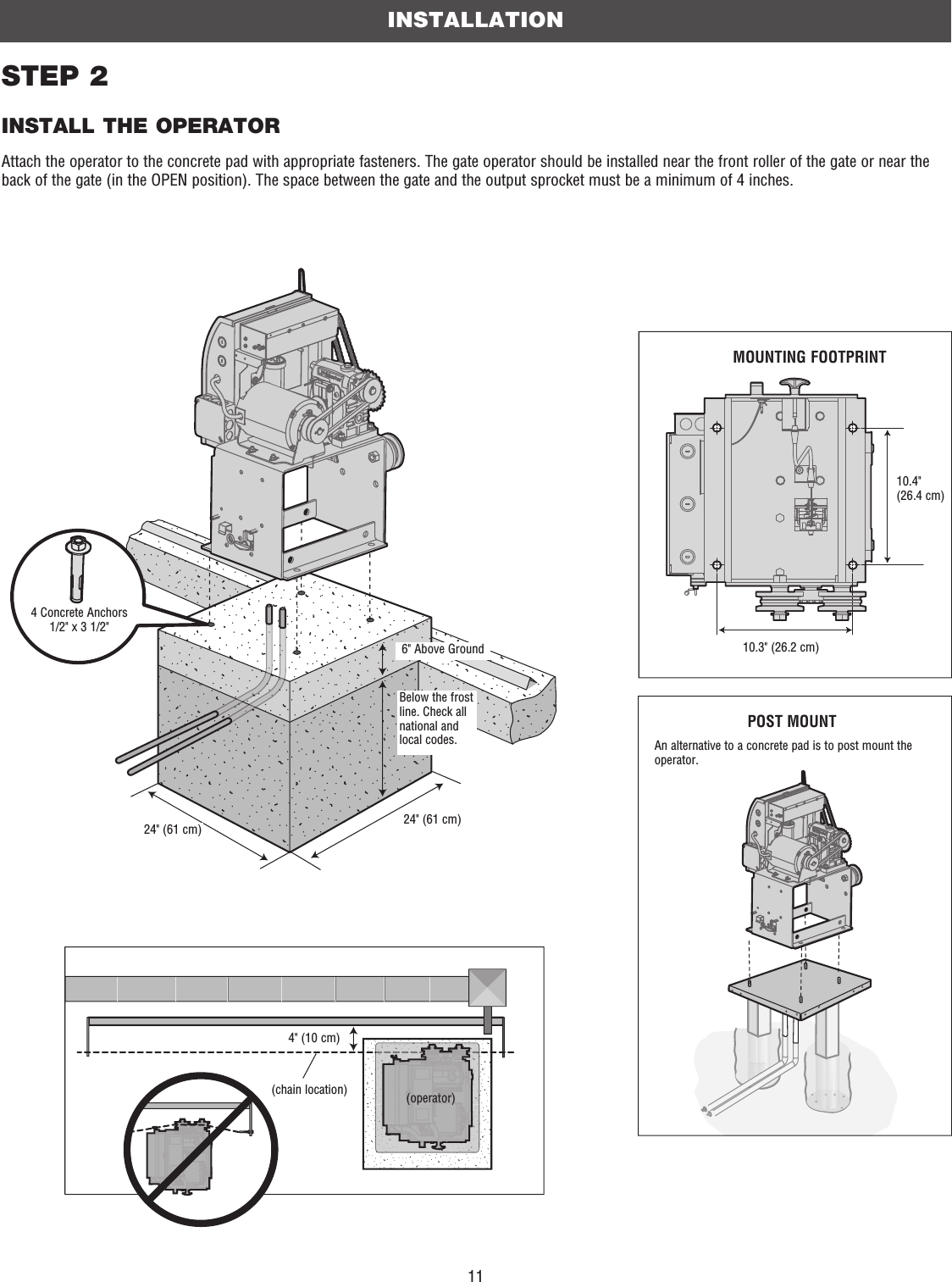
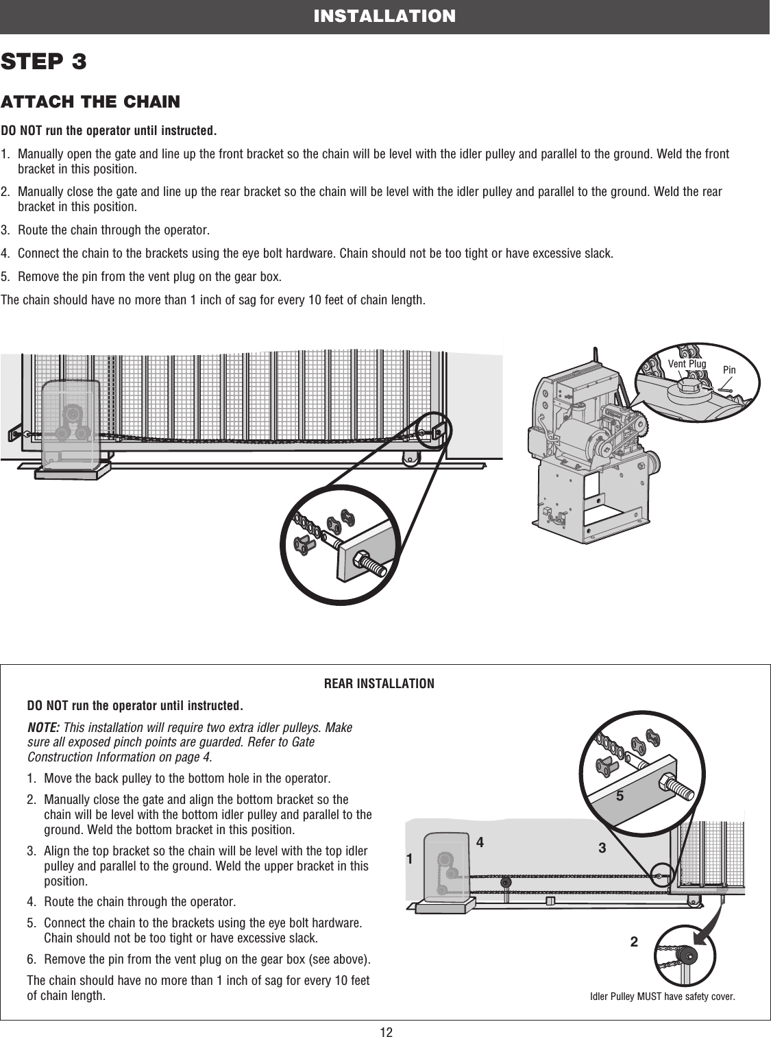
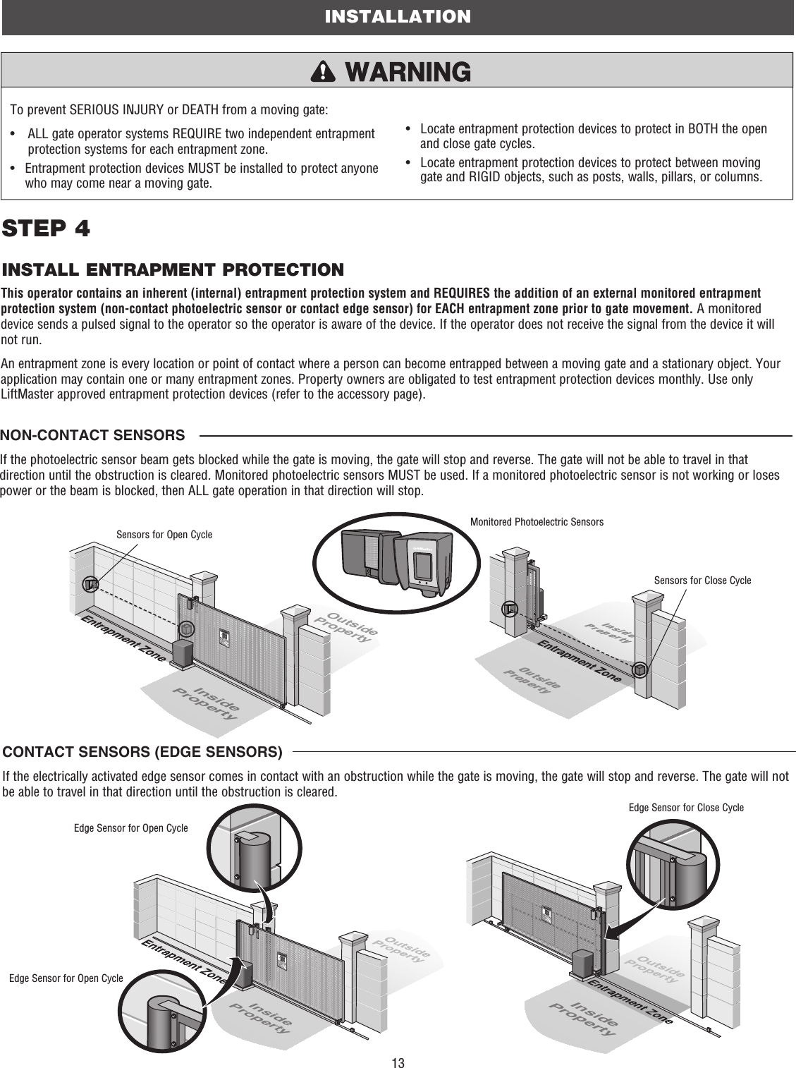
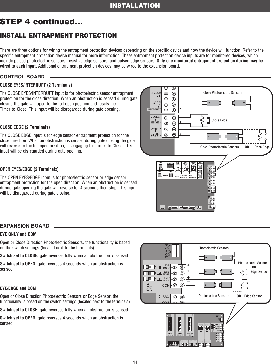
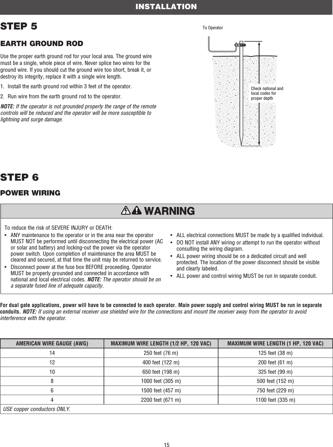
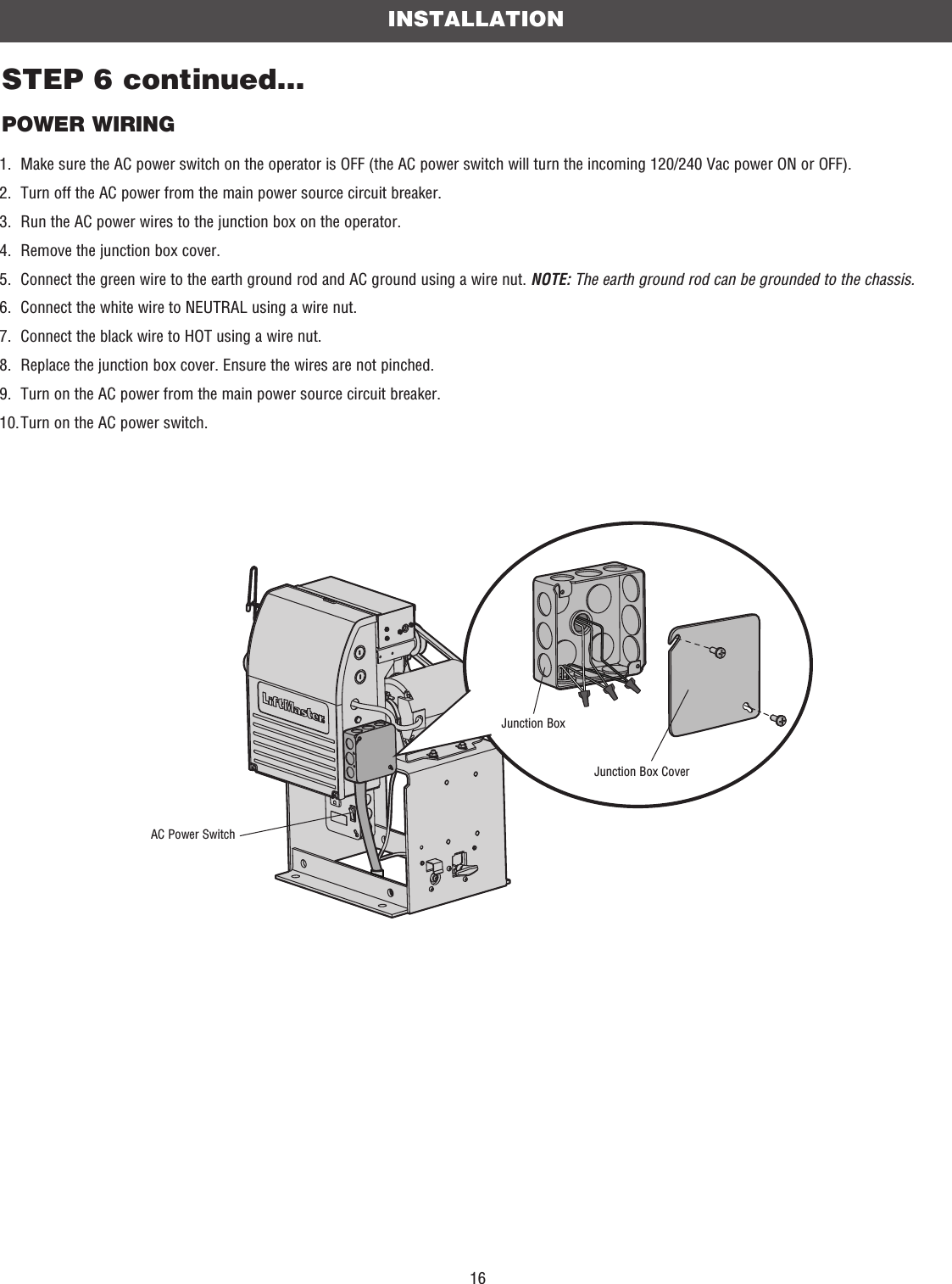
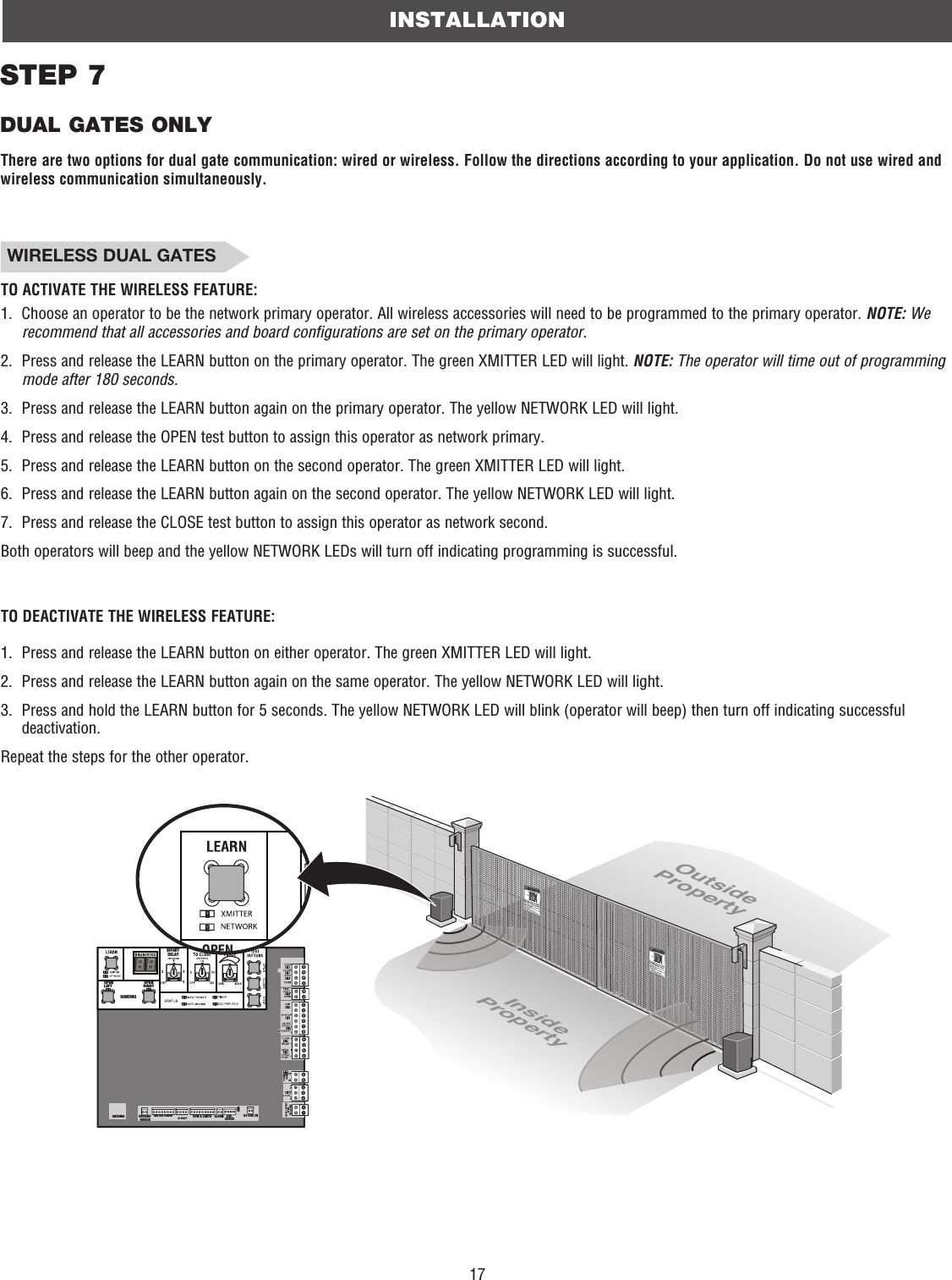
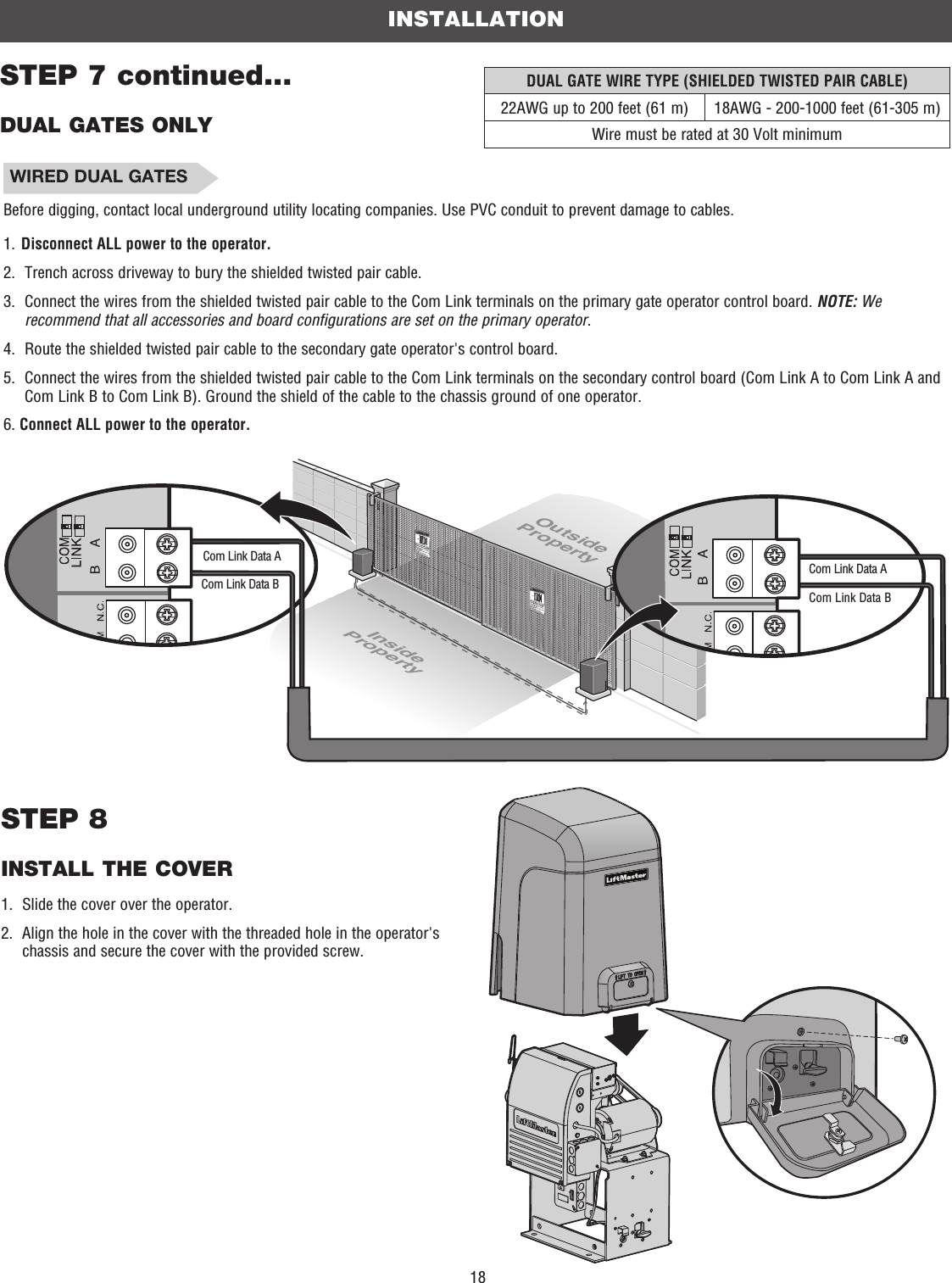
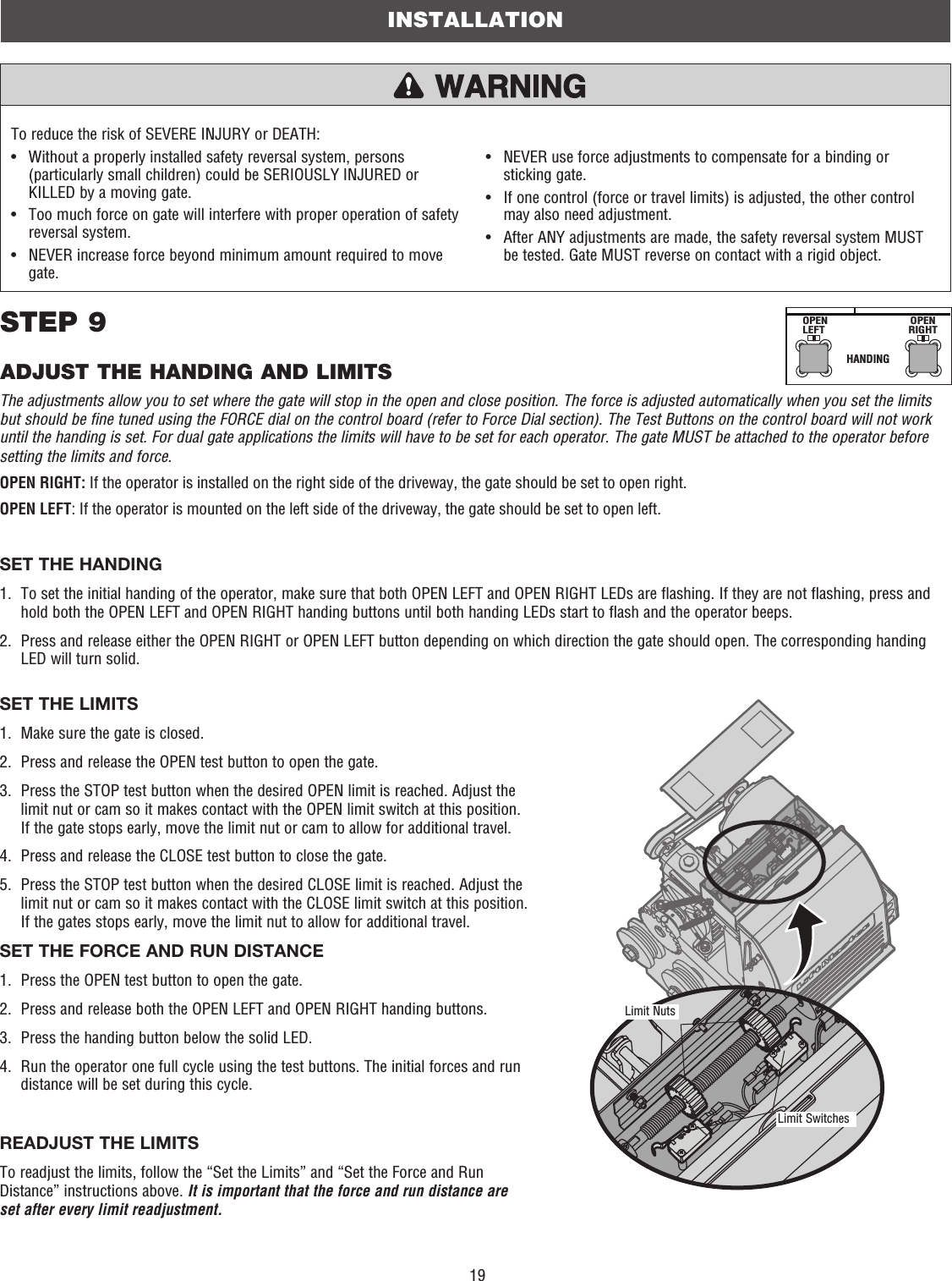
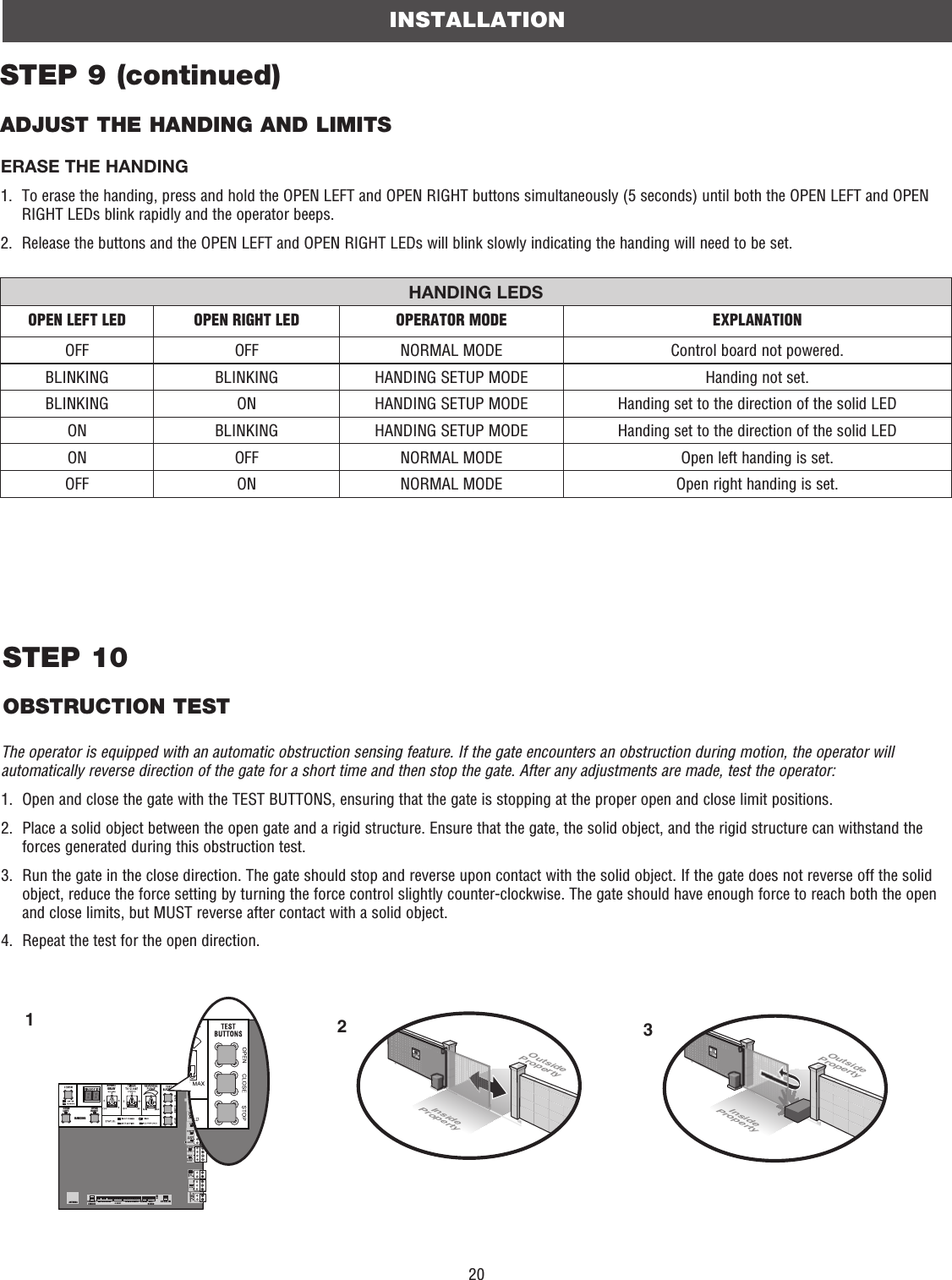
User Manual SL3000 English Manual for FCC 01-37920 Pt1

11STEP 2INSTALL THE OPERATORAttach the operator to the concrete pad with appropriate fasteners. The gate operator should be installed near the front roller of the gate or near the back of the gate (in the OPEN position). The space between the gate and the output sprocket must be a minimum of 4 inches. 4 Concrete Anchors1/2" x 3 1/2"Below the frost line. Check all national and local codes.6" Above Ground24" (61 cm)24" (61 cm)INSTALLATIONMOUNTING FOOTPRINT10.4"(26.4 cm)10.3" (26.2 cm)POST MOUNTAn alternative to a concrete pad is to post mount the operator.4" (10 cm)(chain location) (operator)
12STEP 3ATTACH THE CHAINDO NOT run the operator until instructed.1.   Manually open the gate and line up the front bracket so the chain will be level with the idler pulley and parallel to the ground. Weld the front bracket in this position.2.   Manually close the gate and line up the rear bracket so the chain will be level with the idler pulley and parallel to the ground. Weld the rear bracket in this position.3.   Route the chain through the operator.4.   Connect the chain to the brackets using the eye bolt hardware. Chain should not be too tight or have excessive slack.5.   Remove the pin from the vent plug on the gear box.The chain should have no more than 1 inch of sag for every 10 feet of chain length.INSTALLATION23145REAR INSTALLATIONDO NOT run the operator until instructed.NOTE: This installation will require two extra idler pulleys. Make sure all exposed pinch points are guarded. Refer to Gate Construction Information on page 4.1.   Move the back pulley to the bottom hole in the operator.2.   Manually close the gate and align the bottom bracket so the chain will be level with the bottom idler pulley and parallel to the ground. Weld the bottom bracket in this position. 3.   Align the top bracket so the chain will be level with the top idler pulley and parallel to the ground. Weld the upper bracket in this position.4.   Route the chain through the operator. 5.   Connect the chain to the brackets using the eye bolt hardware. Chain should not be too tight or have excessive slack.6.   Remove the pin from the vent plug on the gear box (see above).The chain should have no more than 1 inch of sag for every 10 feet of chain length.PinVent PlugIdler Pulley MUST have safety cover.
13To prevent SERIOUS INJURY or DEATH from a moving gate:•   ALL gate operator systems REQUIRE two independent entrapment protection systems for each entrapment zone.•   Entrapment protection devices MUST be installed to protect anyone who may come near a moving gate.•   Locate entrapment protection devices to protect in BOTH the open and close gate cycles.•   Locate entrapment protection devices to protect between moving gate and RIGID objects, such as posts, walls, pillars, or columns.NON-CONTACT SENSORSIf the photoelectric sensor beam gets blocked while the gate is moving, the gate will stop and reverse. The gate will not be able to travel in that direction until the obstruction is cleared. Monitored photoelectric sensors MUST be used. If a monitored photoelectric sensor is not working or loses power or the beam is blocked, then ALL gate operation in that direction will stop. This operator contains an inherent (internal) entrapment protection system and REQUIRES the addition of an external monitored entrapment protection system (non-contact photoelectric sensor or contact edge sensor) for EACH entrapment zone prior to gate movement. A monitored device sends a pulsed signal to the operator so the operator is aware of the device. If the operator does not receive the signal from the device it will not run.An entrapment zone is every location or point of contact where a person can become entrapped between a moving gate and a stationary object. Your application may contain one or many entrapment zones. Property owners are obligated to test entrapment protection devices monthly. Use only LiftMaster approved entrapment protection devices (refer to the accessory page).CONTACT SENSORS (EDGE SENSORS)If the electrically activated edge sensor comes in contact with an obstruction while the gate is moving, the gate will stop and reverse. The gate will not be able to travel in that direction until the obstruction is cleared.INSTALLATIONSTEP 4INSTALL ENTRAPMENT PROTECTIONOutsidePropertyInsidePropertyInsidePropertyOutsidePropertyMonitored Photoelectric SensorsSensors for Open CycleSensors for Close CycleInsidePropertyInsidePropertyEdge Sensor for Open CycleEdge Sensor for Open CycleEdge Sensor for Close Cycle
14INSTALLATIONSTEP 4 continued...INSTALL ENTRAPMENT PROTECTIONThere are three options for wiring the entrapment protection devices depending on the specific device and how the device will function. Refer to the specific entrapment protection device manual for more information. These entrapment protection device inputs are for monitored devices, which include pulsed photoelectric sensors, resistive edge sensors, and pulsed edge sensors. Only one monitored entrapment protection device may be wired to each input. Additional entrapment protection devices may be wired to the expansion board.CONTROL BOARDCLOSE EYES/INTERRUPT (2 Terminals)The CLOSE EYES/INTERRUPT input is for photoelectric sensor entrapment protection for the close direction. When an obstruction is sensed during gate closing the gate will open to the full open position and resets the Timer-to-Close. This input will be disregarded during gate opening.CLOSE EDGE (2 Terminals)The CLOSE EDGE input is for edge sensor entrapment protection for the close direction. When an obstruction is sensed during gate closing the gate will reverse to the full open position, disengaging the Timer-to-Close. This input will be disregarded during gate opening.OPEN EYES/EDGE (2 Terminals)The OPEN EYES/EDGE input is for photoelectric sensor or edge sensor entrapment protection for the open direction. When an obstruction is sensed during gate opening the gate will reverse for 4 seconds then stop. This input will be disregarded during gate closing.EXPANSION BOARDEYE ONLY and COMOpen or Close Direction Photoelectric Sensors, the functionality is based on the switch settings (located next to the terminals) Switch set to CLOSE: gate reverses fully when an obstruction is sensedSwitch set to OPEN: gate reverses 4 seconds when an obstruction is sensedEYE/EDGE and COMOpen or Close Direction Photoelectric Sensors or Edge Sensor, the functionality is based on the switch settings (located next to the terminals) Switch set to CLOSE: gate reverses fully when an obstruction is sensedSwitch set to OPEN: gate reverses 4 seconds when an obstruction is sensedCOMMLINKBABIPARTDELAY2468HANDINGOPENLEFTOPENRIGHTANTENNA CURRENT SENSORMOTOR DRIVE RPM & LIMITS ALARM EXP.BOARD24 VAC INCLASS 2 SUPPLY24 VAC500 mA MAXID RESETGNDClose Photoelectric SensorsClose EdgeOpen EdgeOpen Photoelectric Sensors ORSHADOW   INTERUPT      EXITSBCOPNCLSSTPCOMEYEONLYEYE/EDGEEYE/EDGECOM123OPENCLOSETO MAINBOARDPOWER–+++SBCOPNEYEONLYEYE/EDGEEYE/EDGECOM123OPENCLOSETO MAINBOARDPhotoelectric SensorsEdge SensorPhotoelectric Sensors ORPhotoelectric SensorsOREdge Sensor
15For dual gate applications, power will have to be connected to each operator. Main power supply and control wiring MUST be run in separate conduits. NOTE: If using an external receiver use shielded wire for the connections and mount the receiver away from the operator to avoid interference with the operator.INSTALLATIONTo reduce the risk of SEVERE INJURY or DEATH:•   ANY maintenance to the operator or in the area near the operator MUST NOT be performed until disconnecting the electrical power (AC or solar and battery) and locking-out the power via the operator power switch. Upon completion of maintenance the area MUST be cleared and secured, at that time the unit may be returned to service.•   Disconnect power at the fuse box BEFORE proceeding. Operator MUST be properly grounded and connected in accordance with national and local electrical codes. NOTE: The operator should be on a separate fused line of adequate capacity.•   ALL electrical connections MUST be made by a qualified individual.•   DO NOT install ANY wiring or attempt to run the operator without consulting the wiring diagram. •   ALL power wiring should be on a dedicated circuit and well protected. The location of the power disconnect should be visible and clearly labeled.•  ALL power and control wiring MUST be run in separate conduit.STEP 5EARTH GROUND RODUse the proper earth ground rod for your local area. The ground wire must be a single, whole piece of wire. Never splice two wires for the ground wire. If you should cut the ground wire too short, break it, or destroy its integrity, replace it with a single wire length. 1.  Install the earth ground rod within 3 feet of the operator.2.  Run wire from the earth ground rod to the operator.NOTE: If the operator is not grounded properly the range of the remote controls will be reduced and the operator will be more susceptible to lightning and surge damage.Check national and local codes for proper depthTo OperatorSTEP 6 POWER WIRINGAMERICAN WIRE GAUGE (AWG) MAXIMUM WIRE LENGTH (1/2 HP, 120 VAC) MAXIMUM WIRE LENGTH (1 HP, 120 VAC)14  250 feet (76 m) 125 feet (38 m)12 400 feet (122 m) 200 feet (61 m)10 650 feet (198 m) 325 feet (99 m)8 1000 feet (305 m) 500 feet (152 m)6 1500 feet (457 m) 750 feet (229 m)4 2200 feet (671 m) 1100 feet (335 m)USE copper conductors ONLY.
16Junction Box CoverSTEP 6 continued...POWER WIRINGINSTALLATIONJunction Box1.  Make sure the AC power switch on the operator is OFF (the AC power switch will turn the incoming 120/240 Vac power ON or OFF).2.  Turn off the AC power from the main power source circuit breaker.3.  Run the AC power wires to the junction box on the operator.4.  Remove the junction box cover.5.   Connect the green wire to the earth ground rod and AC ground using a wire nut. NOTE: The earth ground rod can be grounded to the chassis.6.  Connect the white wire to NEUTRAL using a wire nut.7.  Connect the black wire to HOT using a wire nut.8.  Replace the junction box cover. Ensure the wires are not pinched.9.  Turn on the AC power from the main power source circuit breaker.10. Turn on the AC power switch.AC Power Switch
17INSTALLATIONSTEP 7DUAL GATES ONLYCOMMLINKBABIPARTDELAY2468HANDINGOPENLEFTOPENRIGHTANTENNA CURRENT SENSORMOTOR DRIVE RPM & LIMITS ALARM EXP.BOARD24 VAC INCLASS 2 SUPPLY24 VAC500 mA MAXID RESETGNDOPENOutsidePropertyInsideProperty WIRELESS DUAL GATESTO ACTIVATE THE WIRELESS FEATURE:1.   Choose an operator to be the network primary operator. All wireless accessories will need to be programmed to the primary operator. NOTE: We recommend that all accessories and board configurations are set on the primary operator.2.   Press and release the LEARN button on the primary operator. The green XMITTER LED will light. NOTE: The operator will time out of programming mode after 180 seconds.3.   Press and release the LEARN button again on the primary operator. The yellow NETWORK LED will light.4.   Press and release the OPEN test button to assign this operator as network primary.5.   Press and release the LEARN button on the second operator. The green XMITTER LED will light.6.   Press and release the LEARN button again on the second operator. The yellow NETWORK LED will light.7.   Press and release the CLOSE test button to assign this operator as network second.Both operators will beep and the yellow NETWORK LEDs will turn off indicating programming is successful.TO DEACTIVATE THE WIRELESS FEATURE:1.   Press and release the LEARN button on either operator. The green XMITTER LED will light.2.   Press and release the LEARN button again on the same operator. The yellow NETWORK LED will light.3.   Press and hold the LEARN button for 5 seconds. The yellow NETWORK LED will blink (operator will beep) then turn off indicating successful deactivation.Repeat the steps for the other operator.There are two options for dual gate communication: wired or wireless. Follow the directions according to your application. Do not use wired and wireless communication simultaneously.
18OutsidePropertyInsidePropertyCom Link Data ACom Link Data BCom Link Data ACom Link Data BDUAL GATE WIRE TYPE (SHIELDED TWISTED PAIR CABLE)22AWG up to 200 feet (61 m) 18AWG - 200-1000 feet (61-305 m)Wire must be rated at 30 Volt minimumINSTALLATIONSTEP 7 continued...DUAL GATES ONLYSTEP 8INSTALL THE COVER1.  Slide the cover over the operator.2.   Align the hole in the cover with the threaded hole in the operator's chassis and secure the cover with the provided screw. WIRED DUAL GATESBefore digging, contact local underground utility locating companies. Use PVC conduit to prevent damage to cables. 1.  Disconnect ALL power to the operator.2.  Trench across driveway to bury the shielded twisted pair cable.3.   Connect the wires from the shielded twisted pair cable to the Com Link terminals on the primary gate operator control board. NOTE: We recommend that all accessories and board configurations are set on the primary operator.4.   Route the shielded twisted pair cable to the secondary gate operator's control board.5.   Connect the wires from the shielded twisted pair cable to the Com Link terminals on the secondary control board (Com Link A to Com Link A and Com Link B to Com Link B). Ground the shield of the cable to the chassis ground of one operator.6. Connect ALL power to the operator.
19The adjustments allow you to set where the gate will stop in the open and close position. The force is adjusted automatically when you set the limits but should be fine tuned using the FORCE dial on the control board (refer to Force Dial section). The Test Buttons on the control board will not work until the handing is set. For dual gate applications the limits will have to be set for each operator. The gate MUST be attached to the operator before setting the limits and force. OPEN RIGHT: If the operator is installed on the right side of the driveway, the gate should be set to open right.OPEN LEFT: If the operator is mounted on the left side of the driveway, the gate should be set to open left.SET THE HANDING1.   To set the initial handing of the operator, make sure that both OPEN LEFT and OPEN RIGHT LEDs are flashing. If they are not flashing, press and hold both the OPEN LEFT and OPEN RIGHT handing buttons until both handing LEDs start to flash and the operator beeps.2.   Press and release either the OPEN RIGHT or OPEN LEFT button depending on which direction the gate should open. The corresponding handing LED will turn solid.To reduce the risk of SEVERE INJURY or DEATH: •   Without a properly installed safety reversal system, persons (particularly small children) could be SERIOUSLY INJURED or KILLED by a moving gate.•   Too much force on gate will interfere with proper operation of safety reversal system.•   NEVER increase force beyond minimum amount required to move gate.•   NEVER use force adjustments to compensate for a binding or sticking gate.•   If one control (force or travel limits) is adjusted, the other control may also need adjustment.•   After ANY adjustments are made, the safety reversal system MUST be tested. Gate MUST reverse on contact with a rigid object.HANDINGOPENLEFTOPENRIGHTSET THE LIMITS1.  Make sure the gate is closed.2.   Press and release the OPEN test button to open the gate.3.   Press the STOP test button when the desired OPEN limit is reached. Adjust the limit nut or cam so it makes contact with the OPEN limit switch at this position. If the gate stops early, move the limit nut or cam to allow for additional travel.4.   Press and release the CLOSE test button to close the gate.5.   Press the STOP test button when the desired CLOSE limit is reached. Adjust the limit nut or cam so it makes contact with the CLOSE limit switch at this position. If the gates stops early, move the limit nut to allow for additional travel.SET THE FORCE AND RUN DISTANCE1.   Press the OPEN test button to open the gate.2.   Press and release both the OPEN LEFT and OPEN RIGHT handing buttons.3.  Press the handing button below the solid LED.4.   Run the operator one full cycle using the test buttons. The initial forces and run distance will be set during this cycle.READJUST THE LIMITSTo readjust the limits, follow the “Set the Limits” and “Set the Force and Run Distance” instructions above. It is important that the force and run distance are set after every limit readjustment. INSTALLATIONSTEP 9ADJUST THE HANDING AND LIMITSLimit NutsLimit Switches
20OutsidePropertyInsidePropertyOutsidePropertyInsideProperty23COMMLINKBABIPARTDELAY2468HANDINGOPENLEFTOPENRIGHTANTENNA CURRENT SENSORMOTOR DRIVE RPM & LIMITS ALARM EXP.BOARD24 VAC INCLASS 2 SUPPLY24 VAC500 mA MAXID RESETGND1INSTALLATIONSTEP 10OBSTRUCTION TESTSTEP 9 (continued)ADJUST THE HANDING AND LIMITSThe operator is equipped with an automatic obstruction sensing feature. If the gate encounters an obstruction during motion, the operator will automatically reverse direction of the gate for a short time and then stop the gate. After any adjustments are made, test the operator:1.   Open and close the gate with the TEST BUTTONS, ensuring that the gate is stopping at the proper open and close limit positions.2.   Place a solid object between the open gate and a rigid structure. Ensure that the gate, the solid object, and the rigid structure can withstand the forces generated during this obstruction test.3.   Run the gate in the close direction. The gate should stop and reverse upon contact with the solid object. If the gate does not reverse off the solid object, reduce the force setting by turning the force control slightly counter-clockwise. The gate should have enough force to reach both the open and close limits, but MUST reverse after contact with a solid object.4.  Repeat the test for the open direction.ERASE THE HANDING1.   To erase the handing, press and hold the OPEN LEFT and OPEN RIGHT buttons simultaneously (5 seconds) until both the OPEN LEFT and OPEN RIGHT LEDs blink rapidly and the operator beeps.2.   Release the buttons and the OPEN LEFT and OPEN RIGHT LEDs will blink slowly indicating the handing will need to be set.HANDING LEDSOPEN LEFT LED OPEN RIGHT LED  OPERATOR MODE EXPLANATIONOFF OFF NORMAL MODE Control board not powered.BLINKING BLINKING HANDING SETUP MODE Handing not set.BLINKING ON HANDING SETUP MODE Handing set to the direction of the solid LEDON BLINKING HANDING SETUP MODE Handing set to the direction of the solid LEDON OFF NORMAL MODE Open left handing is set.OFF ON NORMAL MODE Open right handing is set.
21OPERATOR OVERVIEWMANUAL RELEASE HANDLEPull the manual release handle to manually open and close the gate.JUNCTION BOXPage 31ACCESSORY POWER OUTLETEXPANSION BOARDPages 27-30AC POWER SWITCHThe AC Power switch on the operator will turn the incoming 120 Vac power ON or OFF. CONTROL BOARDPages 22-26DUST GUARDCOVERANTENNARESET BUTTON•   Press the reset button to stop a moving gate during a normal open/close cycle, like a stop button. •   Press the reset button once while the gate is in open position to disable the Timer-to-Close. The gate will stay in the open position. To restart the Timer-to-Close either press the reset button or activate the gate with a programmed remote control.•   Press the reset button to shut off the alarm and reset the operator.LIMIT SWITCHESPage 191 HP OPERATOR
22CONTROL BOARD OVERVIEWCOMMLINKBABIPARTDELAY2468HANDINGOPENLEFTOPENRIGHTANTENNA CURRENT SENSORMOTOR DRIVE RPM & LIMITS ALARM EXP.BOARD24 VAC INCLASS 2 SUPPLY24 VAC500 mA MAXID RESETGNDHANDING BUTTONSPages 19, 23BIPART DELAYPage 23LEARN BUTTONPages 23, 32-33TEST BUTTONSPages 24, 37CONTROL STATION TERMINALSPage 25EXPANSION BOARD CONNECTIONFactory installed.ACCESSORY POWER TERMINALSLOCK TERMINALSPage 26DUAL GATE TERMINALSFor dual gate connection.EYES/EDGE TERMINALSPage 26LOOP TERMINALSPage 25FIRE DEPARTMENT TERMINALSPage 25DIAGNOSTIC DISPLAY Pages 23, 37-39TIMER-TO-CLOSEPage 23FORCE DIALPage 24STATUS LEDSPage 24GROUNDPOWERALARMFactory installed.RPM SENSOR AND LIMITSFactory installed.MOTORFactory installed.PRODUCT ID AND RESETFactory installed.CONTROL BOARD REFERENCECURRENT SENSORFactory installed

Navigation menu