Chamberlain Group The 7545 Linear gate operator w/ 900MHz FHSS transceiver User Manual Part 1
Chamberlain Group Inc, The Linear gate operator w/ 900MHz FHSS transceiver Part 1
Contents
- 1. User Manual Part 1
- 2. User Manual Part 2
User Manual Part 1
LA500 &
LA500-S
VEHICULAR SWING GATE OPERATOR
INSTALLATION MANUAL
UL325
compliant
UL991
compliant
This model is for use on vehicular
passage gates ONLY and not
intended for use on pedestrian
passage gates.
This model is intended for use in
Class I, II, III and IV vehicular swing
gate applications.
THIS PRODUCT IS TO BE
INSTALLED AND SERVICED BY
A TRAINED GATE SYSTEMS
TECHNICIAN ONLY.
Visit www.liftmaster.com to
locate a professional installing
dealer in your area.
Your model may look different than the model illustrated in this manual.

1
When you see these Safety Symbols and Signal Words on the following pages, they
will alert you to the possibility of serious injury or death if you do not comply with
the warnings that accompany them. The hazard may come from something
mechanical or from electric shock. Read the warnings carefully.
When you see this Signal Word on the following pages, it will alert you to the
possibility of damage to your gate and/or the gate operator if you do not comply
with the cautionary statements that accompany it. Read them carefully.
IMPORTANT NOTE
• BEFORE attempting to install, operate or maintain the operator, you must read
and fully understand this manual and follow all safety instructions.
• DO NOT attempt repair or service of your gate operator unless you are an
Authorized Service Technician.
MECHANICAL
ELECTRICAL
SAFETY 1-7
Safety Symbol and Signal Word Review . . . . . . . . . . . . . . . . . . . . . . . . . . . . . . . 1
UL325 Model Classifications . . . . . . . . . . . . . . . . . . . . . . . . . . . . . . . . . . . . . . . . 2
Safety Installation Information . . . . . . . . . . . . . . . . . . . . . . . . . . . . . . . . . . . . . . 3
Gate Construction Information . . . . . . . . . . . . . . . . . . . . . . . . . . . . . . . . . . . . . . 4
Required Entrapment Protection Devices . . . . . . . . . . . . . . . . . . . . . . . . . . . . . . . 5
Important Safety Information . . . . . . . . . . . . . . . . . . . . . . . . . . . . . . . . . . . . .6-7
INTRODUCTION 8-9
Operator Specifications . . . . . . . . . . . . . . . . . . . . . . . . . . . . . . . . . . . . . . . . . . . 8
Carton Inventory & Operator Dimensions . . . . . . . . . . . . . . . . . . . . . . . . . . . . . . 8
Features . . . . . . . . . . . . . . . . . . . . . . . . . . . . . . . . . . . . . . . . . . . . . . . . . . . . . . 9
PREPARATION 10-12
Site Preparation . . . . . . . . . . . . . . . . . . . . . . . . . . . . . . . . . . . . . . . . . . . . .10-11
Mounting Options . . . . . . . . . . . . . . . . . . . . . . . . . . . . . . . . . . . . . . . . . . . . . . 12
INSTALLATION 13-17
Manual Release . . . . . . . . . . . . . . . . . . . . . . . . . . . . . . . . . . . . . . . . . . . . . . . . 13
Determine the Position of the Post Bracket . . . . . . . . . . . . . . . . . . . . . . . . . . . . 13
Determine the Position of the Gate Bracket . . . . . . . . . . . . . . . . . . . . . . . . . . . 14
Weld the Brackets . . . . . . . . . . . . . . . . . . . . . . . . . . . . . . . . . . . . . . . . . . . . . . 14
Attach the Operator to the Brackets . . . . . . . . . . . . . . . . . . . . . . . . . . . . . . . . . 15
Standard Control Box. . . . . . . . . . . . . . . . . . . . . . . . . . . . . . . . . . . . . . . . . . . . 16
Large Metal Control Box (XLM) . . . . . . . . . . . . . . . . . . . . . . . . . . . . . . . . . . . . 17
WIRING 18-24
Wire the Entrapment Protection Devices . . . . . . . . . . . . . . . . . . . . . . . . . . . . . . 18
Earth Ground Rod . . . . . . . . . . . . . . . . . . . . . . . . . . . . . . . . . . . . . . . . . . . . . . 18
Wire the Operator Arm to the Control Board . . . . . . . . . . . . . . . . . . . . . . . . . . . 19
Dual Gates Only . . . . . . . . . . . . . . . . . . . . . . . . . . . . . . . . . . . . . . . . . . . . .20-21
Power Wiring . . . . . . . . . . . . . . . . . . . . . . . . . . . . . . . . . . . . . . . . . . . . . . . .22-23
Connect Batteries . . . . . . . . . . . . . . . . . . . . . . . . . . . . . . . . . . . . . . . . . . . . .23-24
Engage the Operator . . . . . . . . . . . . . . . . . . . . . . . . . . . . . . . . . . . . . . . . . . . . 24
ADJUSTMENT 25-26
Limit and Force Adjustment . . . . . . . . . . . . . . . . . . . . . . . . . . . . . . . . . . . . .25-26
Obstruction Test . . . . . . . . . . . . . . . . . . . . . . . . . . . . . . . . . . . . . . . . . . . . . . . . 26
PROGRAMMING 27
Remote Controls . . . . . . . . . . . . . . . . . . . . . . . . . . . . . . . . . . . . . . . . . . . . . . . 27
Erase All Codes . . . . . . . . . . . . . . . . . . . . . . . . . . . . . . . . . . . . . . . . . . . . . . . . 27
OPERATION 28
Manual Release . . . . . . . . . . . . . . . . . . . . . . . . . . . . . . . . . . . . . . . . . . . . . . . . 28
Reset Button . . . . . . . . . . . . . . . . . . . . . . . . . . . . . . . . . . . . . . . . . . . . . . . . . . 28
Remote Control . . . . . . . . . . . . . . . . . . . . . . . . . . . . . . . . . . . . . . . . . . . . . . . . 28
Party Mode . . . . . . . . . . . . . . . . . . . . . . . . . . . . . . . . . . . . . . . . . . . . . . . . . . . 28
MAINTENANCE 29
Maintenance Chart . . . . . . . . . . . . . . . . . . . . . . . . . . . . . . . . . . . . . . . . . . . . . . 29
Batteries . . . . . . . . . . . . . . . . . . . . . . . . . . . . . . . . . . . . . . . . . . . . . . . . . . . . . 29
ADDITIONAL FEATURES 30-35
Control Board Overview . . . . . . . . . . . . . . . . . . . . . . . . . . . . . . . . . . . . . . . . . . 30
Accessory Features on Control Board . . . . . . . . . . . . . . . . . . . . . . . . . . . . . . . . 31
Expansion Board Overview . . . . . . . . . . . . . . . . . . . . . . . . . . . . . . . . . . . . . . . 32
Accessory Features on Expansion Board . . . . . . . . . . . . . . . . . . . . . . . . . . . . . . 33
Gate Operator Setup Examples . . . . . . . . . . . . . . . . . . . . . . . . . . . . . . . . . . . . 34
Limit Setup with a Remote Control . . . . . . . . . . . . . . . . . . . . . . . . . . . . . . . . . . 35
TROUBLESHOOTING 36-41
Control Board LEDs . . . . . . . . . . . . . . . . . . . . . . . . . . . . . . . . . . . . . . . . . . .36-37
Troubleshooting Chart . . . . . . . . . . . . . . . . . . . . . . . . . . . . . . . . . . . . . . . . .38-41
WIRING DIAGRAMS 42-43
Standard Control Box. . . . . . . . . . . . . . . . . . . . . . . . . . . . . . . . . . . . . . . . . . . . 42
Large Metal Control Box (XLM) . . . . . . . . . . . . . . . . . . . . . . . . . . . . . . . . . . . . 43
ACCESSORIES 44
WARRANTY 45
TABLE OF CONTENTS
SAFETY SYMBOL AND SIGNAL WORD REVIEW
SAFETY
2
In order to complete a proper installation you must satisfy the entrapment
protection chart shown. That means that the installation must have one primary
means of entrapment protection and one independent secondary means of
entrapment protection. Both primary and secondary entrapment protection
methods must be designed, arranged or configured to protect against
entrapments in both the open and close directions of gate travel.
For Example: For a gate system that is installed on a single-family residence
(UL325 Class I) you must provide the following: As your primary type of
entrapment protection you must provide
• Type A - Inherent (built into the operator) entrapment sensing and at
least one of the following as your secondary entrapment
protection:
• Type B1 - Non-contact sensors such as photoelectric sensors,
• Type B2 - Contact sensors such as gate edges
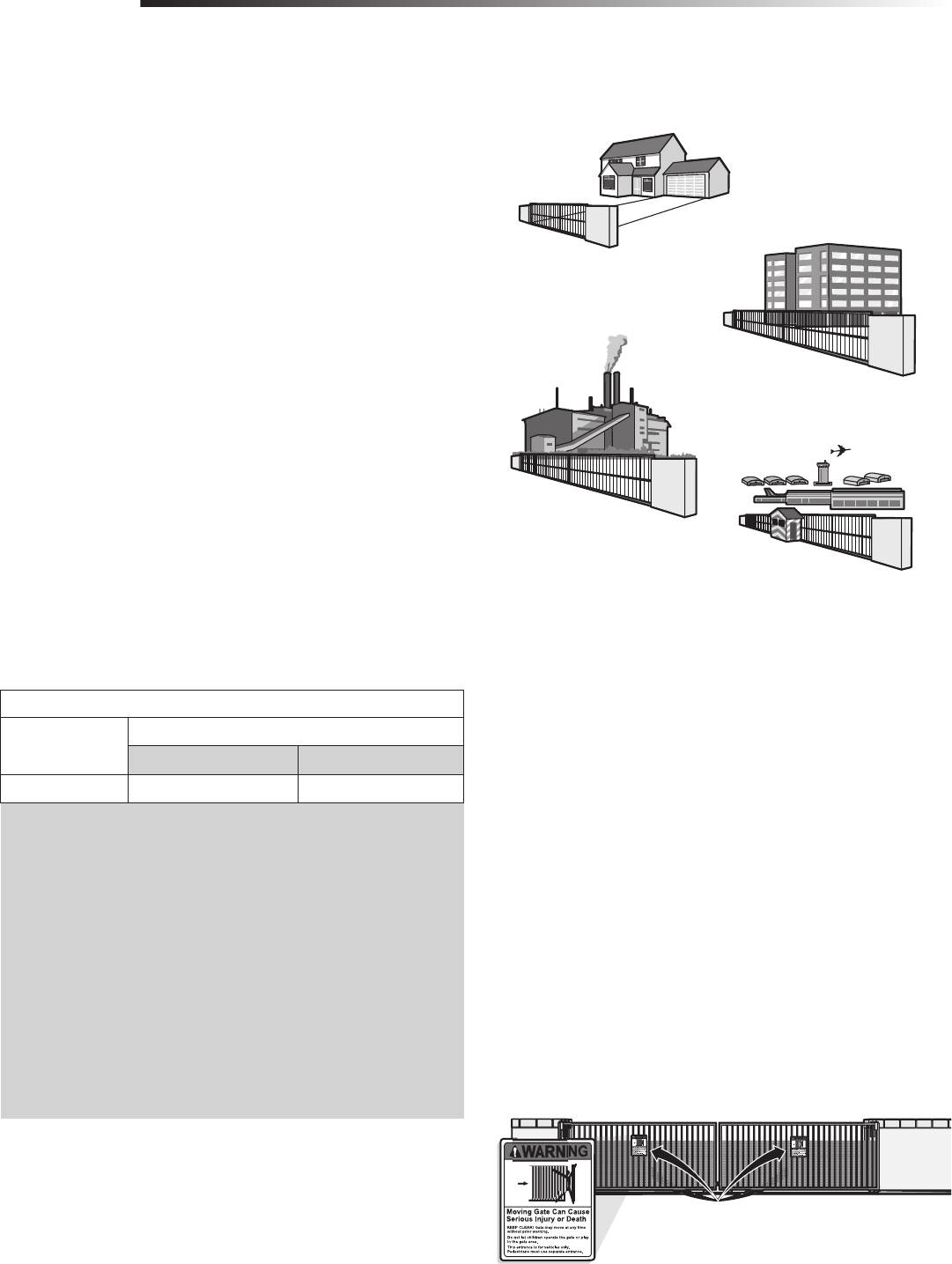
CLASS I – RESIDENTIAL VEHICULAR GATE OPERATOR
A vehicular gate operator (or system) intended for use in a home of one-to four
single family dwellings, or a garage or parking area associated therewith.
CLASS II – COMMERCIAL/GENERAL ACCESS VEHICULAR
GATE OPERATOR
A vehicular gate operator (or system) intended for use in a commercial location or
building such as a multi-family housing unit (five or more single family units) hotel,
garage, retail store or other building servicing the general public.
CLASS III – INDUSTRIAL/LIMITED ACCESS VEHICULAR
GATE OPERATOR
A vehicular gate operator (or system) intended for use in a industrial location or
building such as a factory or loading dock area or other location not intended to
service the general public.
CLASS IV– RESTRICTED ACCESS VEHICULAR GATE
OPERATOR
A vehicular gate operator (or system) intended for use in a guarded industrial
location or building such as an airport security area or other restricted access
locations not servicing the general public, in which unauthorized access is prevented
via supervision by security personnel.
UL325 ENTRAPMENT PROTECTION REQUIREMENTS
This chart illustrates the entrapment protection requirements for the UL325 classes.
NOTE: UL requires that all installations must have warning signs placed in plain
view on both sides of the gate to warn pedestrians of the dangers of motorized gate
systems.
I
II
III
IV
UL325 MODEL CLASSIFICATIONS
SAFETY
UL325 MODEL CLASSIFICATIONS
GATE OPERATOR ENTRAPMENT PROTECTION
UL325 Classification Swing Gate Operator
Primary Type Secondary Type
CLASS I-CLASS IV A B1 or B2
3
1. Vehicular gate systems provide convenience and security. Gate systems are
comprised of many component parts. The gate operator is only one
component. Each gate system is specifically designed for an individual
application.
2. Gate operating system designers, installers and users must take into account
the possible hazards associated with each individual application. Improperly
designed, installed or maintained systems can create risks for the user as
well as the bystander. Gate systems design and installation must reduce
public exposure to potential hazards.
3. A gate operator can create high levels of force in its function as a component
part of a gate system. Therefore, safety features must be incorporated into
every design. Specific safety features include:
• Gate Edges • Guards for Exposed Rollers
• Photoelectric Sensors • Screen Mesh
• Vertical Posts • Instructional and Precautionary Signage
4. Install the gate operator only when:
a. The operator is appropriate for the construction and the usage class of the
gate.
b. All openings of a horizontal slide gate are guarded or screened from the
bottom of the gate to a minimum of 4 feet (1.2 m) above the ground to
prevent a 2-1/4 inches (6 cm) diameter sphere from passing through the
openings anywhere in the gate, and in that portion of the adjacent fence
that the gate covers in the open position.
c. All exposed pinch points are eliminated or guarded, and guarding is
supplied for exposed rollers.
5. The operator is intended for installation only on gates used for vehicles.
Pedestrians must be supplied with a separate access opening. The pedestrian
access opening shall be designed to promote pedestrian usage. Locate the
gate such that persons will not come in contact with the vehicular gate during
the entire path of travel of the vehicular gate.
6. The gate must be installed in a location so that enough clearance is supplied
between the gate and adjacent structures when opening and closing to reduce
the risk of entrapment. Swinging gates shall not open into public access
areas.
7. The gate must be properly installed and work freely in both directions prior
to the installation of the gate operator.
8. Controls intended for user activation must be located at least 6 feet (1.8 m)
away from any moving part of the gate and where the user is prevented
from reaching over, under, around or through the gate to operate the
controls. Outdoor or easily accessible controls shall have a security feature to
prevent unauthorized use.
9. The Stop and/or Reset (if provided separately) must be located in the
line-of-sight of the gate. Activation of the reset control shall not cause the
operator to start.
10. A minimum of two (2) WARNING SIGNS shall be installed, one on each side
of the gate where easily visible.
11. For a gate operator utilizing a non-contact sensor:
a. Reference owner’s manual regarding placement of non-contact sensor for
each type of application.
b. Care shall be exercised to reduce the risk of nuisance tripping, such as
when a vehicle trips the sensor while the gate is still moving.
c. One or more non-contact sensors shall be located where the risk of
entrapment or obstruction exists, such as the perimeter reachable by a
moving gate or barrier.
12. For a gate operator utilizing a contact sensor such as an edge sensor:
a. One or more contact sensors shall be located where the risk of
entrapment or obstruction exists, such as at the leading edge, trailing
edge and post mounted both inside and outside of a vehicular horizontal
slide gate.
b. One or more contact sensors shall be located at the bottom edge of a
vehicular vertical lift gate.
c. A hard wired contact sensor shall be located and its wiring arranged so
the communication between the sensor and the gate operator is not
subject to mechanical damage.
d. A wireless contact sensor such as the one that transmits radio frequency
(RF) signals to the gate operator for entrapment protection functions shall
be located where the transmission of the signals are not obstructed or
impeded by building structures, natural landscaping or similar obstruction.
A wireless contact sensor shall function under the intended end-use
conditions.
e. One or more contact sensors shall be located on the inside and outside
leading edge of a swing gate. Additionally, if the bottom edge of a swing
gate is greater than 6 inches (152 mm) above the ground at any point in
its arc of travel, one or more contact sensors shall be located on the
bottom edge.
f. One or more contact sensors shall be located at the bottom edge of a
vertical barrier (arm).
SAFETY INSTALLATION INFORMATION
SAFETY
SAFETY INSTALLATION INFORMATION
4
1. GENERAL REQUIREMENTS
1.1 Gates shall be constructed in accordance with the provisions given for the
appropriate gate type listed, refer to ASTM F2200 for additional gate types.
1.2 Gates shall be designed, constructed and installed to not fall over more than
45 degrees from the vertical plane, when a gate is detached from the
supporting hardware.
1.3 Gates shall have smooth bottom edges, with vertical bottom edged
protrusions not exceeding 0.50 inches (12.7 mm) when other than the
exceptions listed in ASTM F2200.
1.4 The minimum height for barbed tape shall not be less than 8 feet (2.44 m)
above grade and for barbed wire shall not be less than 6 feet (1.83 m)
above grade.
1.5 An existing gate latch shall be disabled when a manually operated gate is
retrofitted with a powered gate operator.
1.6 A gate latch shall not be installed on an automatically operated gate.
1.7 Protrusions shall not be permitted on any gate, refer to ASTM F2200 for
Exceptions.
1.8 Gates shall be designed, constructed and installed such that their movement
shall not be initiated by gravity when an automatic operator is disconnected.
1.9 A pedestrian gate shall not be incorporated into a vehicular gate panel or
that portion of the adjacent fence that the gate covers in the open position.
2. SPECIFIC APPLICATIONS
2.1 Any non-automated gate that is to be automated shall be upgraded to
conform to the provisions of this specification.
2.2 This specification shall not apply to gates generally used for pedestrian
access and to vehicular gates not to be automated.
2.3 Any existing automated gate, when the operator requires replacement, shall
be upgraded to conform to the provisions of this specification in effect at
that time.
3. VEHICULAR HORIZONTAL SLIDE GATES
3.1 The following provisions shall apply to Class I, Class II and Class III vehicular
horizontal slide gates:
3.1.1 All weight bearing exposed rollers 8 feet (2.44 m), or less, above grade
shall be guarded or covered.
3.1.2 All openings located between 48 inches (1.22 m) and 72 inches (1.83 m)
above grade shall be designed, guarded or screened to prevent a 4 inch
(102 mm) diameter sphere from passing through the openings anywhere in
the gate, and in that portion of the adjacent fence that covers in the open
position.
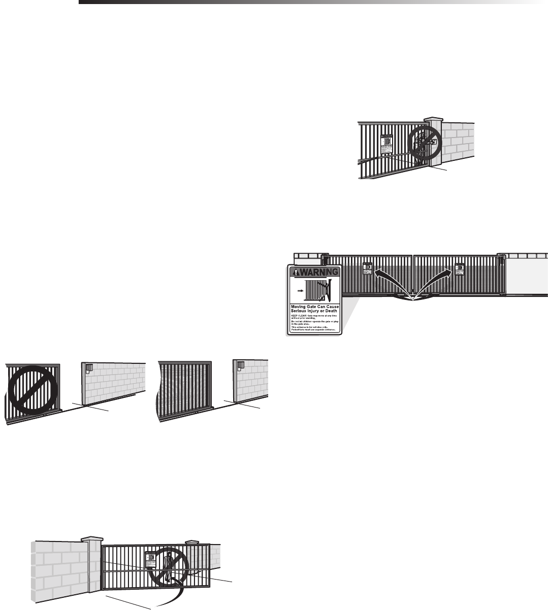
4. VEHICULAR HORIZONTAL SWING GATES
4.1 The following provisions shall apply to Class 1, Class II and Class III vehicular
horizontal swing gates:
4.1.1 Gates shall be designed, constructed and installed so as not to create an
entrapment area between the gate and the supporting structure or other
fixed object when the gate moves toward the fully open position, subject to
the provisions in the 4.1.1.1 and 4.1.1.2.
4.1.1.1 The width of an object (such as a wall, pillar or column) covered by a swing
gate when in the open position shall not exceed 4 inches (102 mm),
measured from the centerline of the pivot point of the gate, refer to ASTM
F2200 for exception.
4.1.1.2 Except for the zone specified in Section 4.1.1.1, the distance between a
fixed object such as a wall, pillar or column, and a swing gate when in the
open position shall not be less than 16 inches (406 mm), refer to ASTM
F2200 for exception.
4.2 Class IV vehicular horizontal swing gates shall be designed, constructed and
installed in accordance with security related parameters specific to the
application in question.
GATE CONSTRUCTION INFORMATION
SAFETY
GATE CONSTRUCTION INFORMATION
Vehicular gates should be installed in accordance with ASTM F2200: Standard Specification for Automated Vehicular Gate Construction. For a copy, contact ASTM directly at
610-832-9585 or www.astm.org.
3.1.3 A gap, measured in the horizontal plane parallel to the roadway, between a
fixed stationary object nearest the roadway, (such as a gate support post)
and the gate frame when the gate is in either the fully open position or the
fully closed position, shall not exceed 2 1/4 inches (57 mm), refer to ASTM
F2200 for Exception.
3.1.4 Positive stops shall be required to limit travel to the designed fully open and
fully closed positions. These stops shall be installed at either the top of the
gate, or at the bottom of the gate where such stops shall horizontally or
vertically project no more than is required to perform their intended
function.
3.1.5 All gates shall be designed with sufficient lateral stability to assure that the
gate will enter a receiver guide, refer to ASTM F2200 for panel types.
3.2 The following provisions shall apply to Class IV vehicular horizontal slide
gates:
3.2.1 All weight bearing exposed rollers 8 feet (2.44 m), or less, above grade
shall be guarded or covered.
3.2.2 Positive stops shall be required to limit travel to the designed fully open and
fully closed positions. These stops shall be installed at either the top of the
gate, or at the bottom of the gate where such stops shall horizontally or
vertically project no more than is required to perform their intended
function.
5
To prevent SERIOUS INJURY or DEATH from a moving gate:
• Entrapment protection devices MUST be installed to protect anyone who may
come near a moving gate.
• Locate entrapment protection devices to protect in BOTH the open and close
gate cycles.
• Locate entrapment protection devices to protect between moving gate and
RIGID objects, such as posts or walls.
NON-CONTACT SENSORS
If the photoelectric sensor beam gets blocked while the gate is moving, the gate will stop and reverse. The gate will not be able to travel in that direction until the obstruction
is cleared. It is best to use monitored photoelectric sensors, model CPS-UN4. If a monitored photoelectric sensor is not working or loses power or the beam is blocked, then ALL
gate operation in that direction will stop. Unmonitored photoelectric sensor models AOMRON and RETROAB are also acceptable.
CONTACT SENSORS (EDGE SENSORS)
If the electrically activated edge sensor comes in contact with an obstruction while the gate is moving, the gate will stop and reverse. The gate will not be able to travel in that
direction until the obstruction is cleared. Use non monitored edge sensor models G65MG0204, G65MGR020, or G65MGS020.
REQUIRED ENTRAPMENT PROTECTION DEVICES
SAFETY
REQUIRED ENTRAPMENT PROTECTION DEVICES
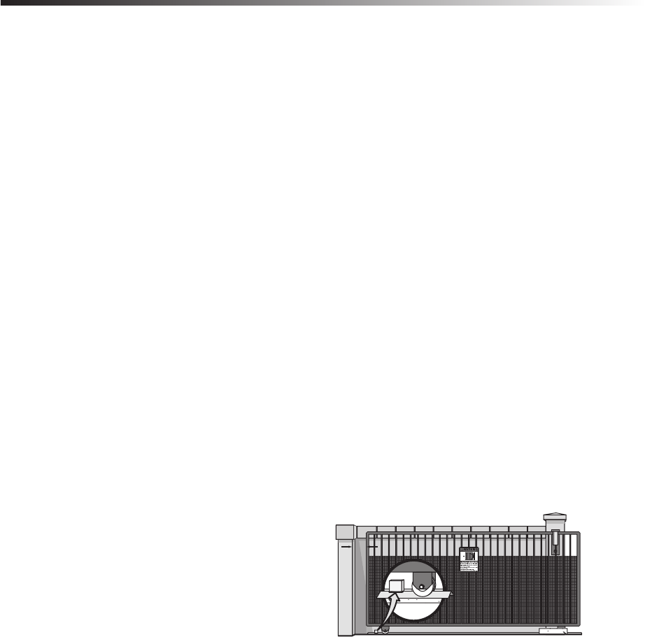
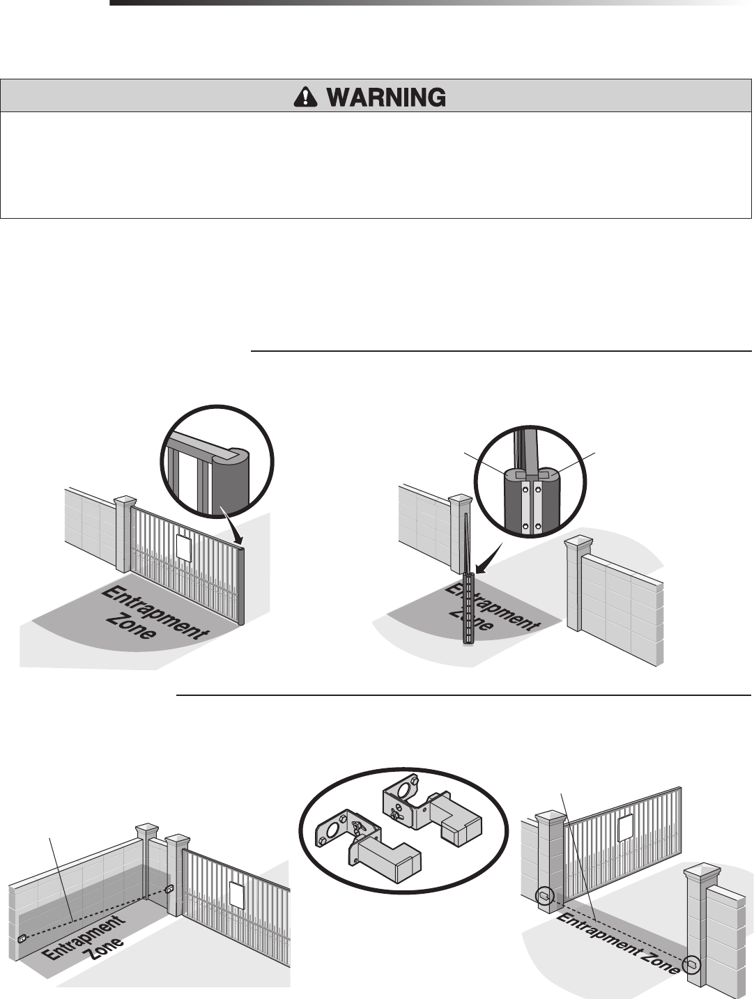
An entrapment zone is every location or point of contact where a person can become entrapped between a moving gate and a stationary object. All gate operator systems
REQUIRE two independent entrapment protection systems for each entrapment zone. This operator contains an inherent (internal) entrapment protection system (the primary
entrapment protection system) and REQUIRES the addition of an external entrapment protection system (non-contact photoelectric sensor or contact safety edge sensor) for
EACH entrapment zone.
Your application may contain one or many entrapment zones. Property owners are obligated to test entrapment protection devices monthly.
Edge Sensor for Open Cycle Edge Sensor for Close Cycle
3 Edge Contact Sensor
Safety Non-Contact Sensor
Sensor for Open Cycle
Sensor for Close Cycle
6
INSTALLATION
To prevent SERIOUS INJURY or DEATH from a moving gate:
• Pinch points must be guarded at all times. Install enclosed-style gate tracks and
roller guards.
• Place screen mesh 4 feet (1.2 m) high on the gate to prevent access through
openings anywhere the gate may travel.
• Mount controls at least 6 feet (1.8 m) from the gate or ANY moving part of the
gate.
• Install Warning signs on EACH side of gate in PLAIN VIEW. Permanently secure
each Warning sign in a suitable manner using fastening holes.
• This operator is intended for vehicular use only. To prevent INJURY to
pedestrians, a separate pedestrian access should be supplied, visible from the
gate. Locate the pedestrian access where there is not a chance of INJURY at any
point during full movement of the gate.
• Contact sensors MUST be located at the leading and trailing edges, and post
mounted both inside and outside a horizontal swing gate. Non-contact sensors
such as photo eyes MUST be mounted across the gate opening and operate
during BOTH the open and close cycles.
• Entrapment protection devices MUST be installed to protect anyone who may
come near a moving gate.
• Locate entrapment protection devices to protect in BOTH the open and close
gate cycles.
• Locate entrapment protection devices to protect between moving gate and RIGID
objects, such as posts or walls.
• Too much force on gate will interfere with proper operation of safety reversal
system.
• NEVER increase force beyond minimum amount required to move gate.
• NEVER use force adjustments to compensate for a binding or sticking gate.
• If one control (force or travel limits) is adjusted, the other control may also
need adjustment.
• After ANY adjustments are made, the safety reversal system MUST be tested.
Gate MUST reverse on contact with a rigid object.
• DO NOT touch the heater when switch is on, heater may be hot.
• To AVOID damaging gas, power or other underground utility lines, contact
underground utility locating companies BEFORE digging more than 18 inches
(46 cm) deep.
• ALWAYS wear protective gloves and eye protection when changing the battery
or working around the battery compartment.
To reduce the risk of SEVERE INJURY or DEATH:
• ANY maintenance to the operator or in the area near the operator MUST NOT
be performed until disconnecting the electrical power (AC or solar and battery)
and locking-out the power via the operator power switch. Upon completion of
maintenance the area MUST be cleared and secured, at that time the unit may
be returned to service.
• Disconnect power at the fuse box BEFORE proceeding. Operator MUST be
properly grounded and connected in accordance with national and local
electrical codes. NOTE: The operator should be on a separate fused line of
adequate capacity.
• ALL electrical connections MUST be made by a qualified individual.
• DO NOT install ANY wiring or attempt to run the operator without consulting the
wiring diagram. We recommend that you install an edge sensor BEFORE
proceeding with the control station installation.
• ALL power wiring should be on a dedicated circuit and well protected. The
location of the power disconnect should be visible and clearly labeled.
• ALL power and control wiring MUST be run in separate conduit.
WIRING
To reduce the risk of SEVERE INJURY or DEATH:
• Without a properly installed safety reversal system, persons (particularly small
children) could be SERIOUSLY INJURED or KILLED by a moving gate.
• Too much force on gate will interfere with proper operation of safety reversal
system.
• NEVER increase force beyond minimum amount required to move gate.
• NEVER use force adjustments to compensate for a binding or sticking gate.
• If one control (force or travel limits) is adjusted, the other control may also
need adjustment.
• After ANY adjustments are made, the safety reversal system MUST be tested.
Gate MUST reverse on contact with a rigid object.
ADJUSTMENT
IMPORTANT SAFETY INFORMATION
SAFETY
IMPORTANT SAFETY INFORMATION
7
To prevent SERIOUS INJURY or DEATH from a moving gate:
• Entrapment protection devices MUST be installed to protect anyone who may
come near a moving gate.
• Locate entrapment protection devices to protect in BOTH the open and close
gate cycles.
• Locate entrapment protection devices to protect between moving gate and RIGID
objects, such as posts or walls.
ADDITIONAL FEATURES
To reduce the risk of SEVERE INJURY or DEATH:
• READ AND FOLLOW ALL INSTRUCTIONS.
• ANY maintenance to the operator or in the area near the operator MUST NOT
be performed until disconnecting the electrical power (AC or solar and battery)
and locking-out the power via the operator power switch. Upon completion of
maintenance the area MUST be cleared and secured, at that time the unit may
be returned to service.
• Disconnect power at the fuse box BEFORE proceeding. Operator MUST be
properly grounded and connected in accordance with national and local
electrical codes. NOTE: The operator should be on a separate fused line of
adequate capacity.
• NEVER let children operate or play with gate controls. Keep the remote control
away from children.
• ALWAYS keep people and objects away from the gate. NO ONE SHOULD CROSS
THE PATH OF THE MOVING GATE.
• Test the gate operator monthly. The gate MUST reverse on contact with a rigid
object or reverse when an object activates the non-contact sensors. After
adjusting the force or the limit of travel, retest the gate operator. Failure to
adjust and retest the gate operator properly can increase the risk of INJURY or
DEATH.
• Use the manual disconnect release ONLY when the gate is not moving.
• KEEP GATES PROPERLY MAINTAINED. Read the owner’s manual. Have a
qualified service person make repairs to gate hardware.
• ALL maintenance MUST be performed by a LiftMaster professional.
• Activate gate ONLY when it can be seen clearly, is properly adjusted and there
are no obstructions to gate travel.
• To reduce the risk of FIRE or INJURY to persons use ONLY LiftMaster part
29-NP712 for replacement batteries.
• SAVE THESE INSTRUCTIONS.
MAINTENANCE AND OPERATION
To protect against fire and electrocution:
• DISCONNECT power (AC or solar and battery) BEFORE installing or servicing
operator.
For continued protection against fire:
• Replace ONLY with fuse of same type and rating.
TROUBLESHOOTING
• ALWAYS wear protective gloves and eye protection when changing the battery
or working around the battery compartment.
IMPORTANT SAFETY INFORMATION
SAFETY
IMPORTANT SAFETY INFORMATION
8
This model is intended for use in vehicular swing gate applications:
OPERATOR SPECIFICATIONS + CARTON INVENTORY & OPERATOR DIMENSIONS
INTRODUCTION
OPERATOR SPECIFICATIONS
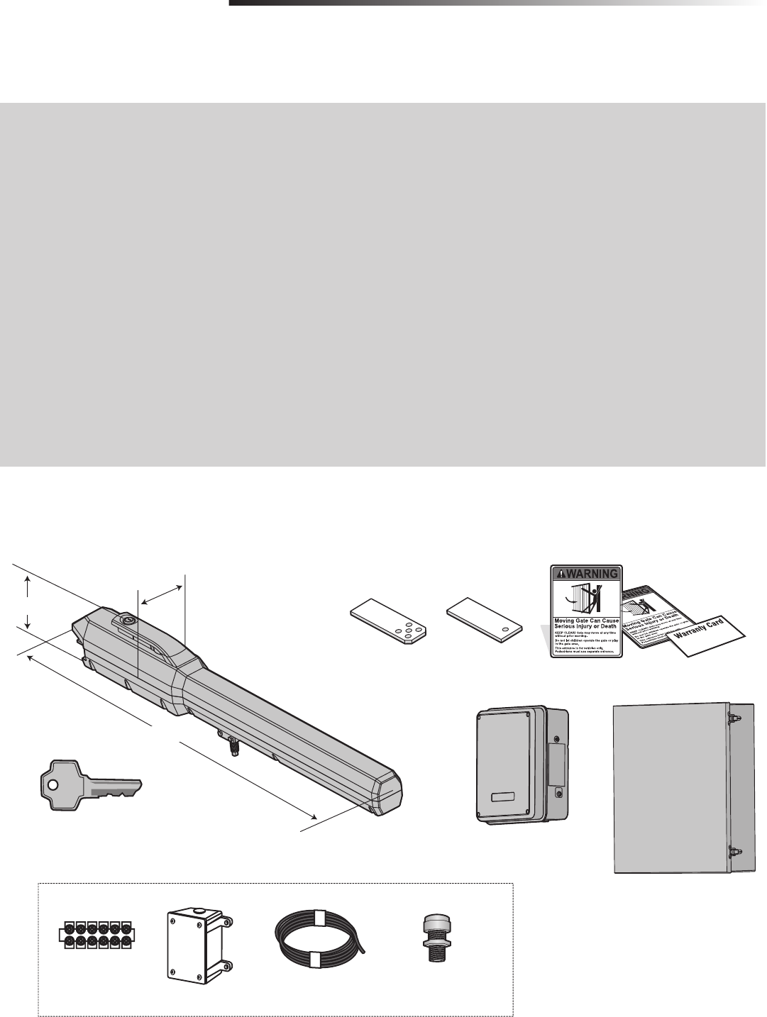
CARTON INVENTORY & OPERATOR DIMENSIONS
NOT SHOWN: Documentation Packet, Hardware Bag
Key (2)
Warning Signs (2) and Warranty Card
Standard Control Box with
Batteries 12 Vdc 7AH (2)
Operator
Model LA500 (1)
Model LA500-S (2)
5.83" (14.8 cm)
Gate Classifications: CLASS I, II, III, & IV
Main AC Supply: 120 Vac or 240 Vac
Solar Power Max: 24 Vdc at 50 watts max.
Input Rating: 8 Amps at 120 Vac or 1 Amp at 240 Vac
Input Rating Excluding Accessory Outlets: 2 Amps at 120 Vac or 1
Amp at 240 Vac
*Input Rating of Accessory Outlets: 6 Amps at 120 Vac
*NOTE: The accessory outlets are not connected for the 240 Vac rating.
Main Supply (Motor): 24 Vdc
Accessory Power: 24 Vdc nominal Class II battery voltage source is
limited to:
• Accessory wire up to 50 feet - 500 mA
• Accessory wire 50 feet up to 250 feet - 250 mA
• Accessory wire 250 feet up to 1000 feet - 100 mA
NOTE: Increased accessory power drawn from the operator will shorten the
battery life (solar applications ONLY).
Full Cycle Time: 32 seconds (90 degree opening)
Maximum Travel Range: 115 degrees
Maximum Gate Weight/Length:
• 1600 lbs./8 foot
• 800 lbs./16 foot
• 600 lbs./18 foot
Ambient Temperature: -40°C to 60°C (-40°F to 140°F)
Fuse Protection Battery: 30 Amp
Fuse Protection DC Power: 30 Amp
Daily cycle rate for direct plug-in transformer power:
300 cycles/day
Daily Cycle Rate for toroid transformer (accessory) power:
300 cycles/day semi-continuous duty
4.21" (10.7 cm)
40.35" (102.5 cm)
Large Metal Control Box (XLM),
ordered separately (batteries
not included)
OR
Post Bracket Gate Bracket
MODEL LA500-S ONLY
Terminal Block
Connector
Junction Box Extension Cable Watertight Connector (2)

9
FEATURES
INTRODUCTION
FEATURES
OPERATOR FEATURES
CONTROL BOARD FEATURES
EXPANSION BOARD FEATURES
• Advanced “Centerpiece” Control Board
• EMI AC Power Surge Protection and Filter Board
- Main AC voltage input selection: 120 Vac (factory setting) or 240 Vac (field
change)
• DC motor with extended brush life
• AC powered with integrated EverCharge® Power Management System
• 24 Vdc accessory power
• Programmable with up to 50 remote controls and 2 keyless entries. Compatible
with MyQ™ devices and Security✚ 2.0™ codes at either 310, 315, 390 MHz, or
433 MHz
• Manual - Secure power failure selection
• SAMS compatible
• Slow-start and slow-stop gate motion
• Reset Button
• Audible Alarm
• Standard Control box has integrated internal antenna with external antenna
option. Large Metal Control Box (XLM) has external antenna.
• Electronic limit adjustment and control from the remote control
• Wireless primary/secondary (refer to pages 20 and 21)
• Electronic Limit adjustment and control
• Adjustable reversal force
• Adjustable Timer-to-Close (TTC)
• Maximum Run Timer
• Bipart Delay switch (dual gate applications)
• Feedback and Diagnostic LEDs
• Integrated Radio Receiver, Single Button Control (SBC) and 3-Button Station
control, three radio frequencies supporting Security✚ 2.0™
• COMMANDS:
- OPEN, CLOSE, or STOP: accessory connection and on-board button
- Single Button Close (SBC): accessory connection
- FIRE DEPARTMENT OPEN: accessory connection
- INTEGRATED RADIO RECEIVER:
• LOOPS:
- EXIT, SHADOW, or INTERRUPT LOOP: accessory connection
• Plug-in Loop Detector Connectors (Model LOOPDETLM Loop Detector)
- SHADOW
- INTERRUPT
- EXIT, with Fail Open/Fail Close selection
• Quick-Close ON/OFF selection switch
• AC Fail Open/Battery selection switch
• Low Battery Open/Close selection switch
• Anti-Tail ON/OFF selection switch
• Single Button Control (SBC) accessory connection
• 3-Button station accessory connection
• AUX Relays (2) each independently selectable operation:
- OPEN LIMIT: ON at open limit switch
- CLOSE LIMIT: OFF at close limit switch
- GATE MOVING: ON with gate moving
- PRE-ALERT DELAY: ON 3 seconds before gate motion
- TAMPER: ON when gate manually pulled from close limit
- POWER: ON with AC or Solar power available
- CYCLE QUANTITY: LEDs blink operational cycle count
10
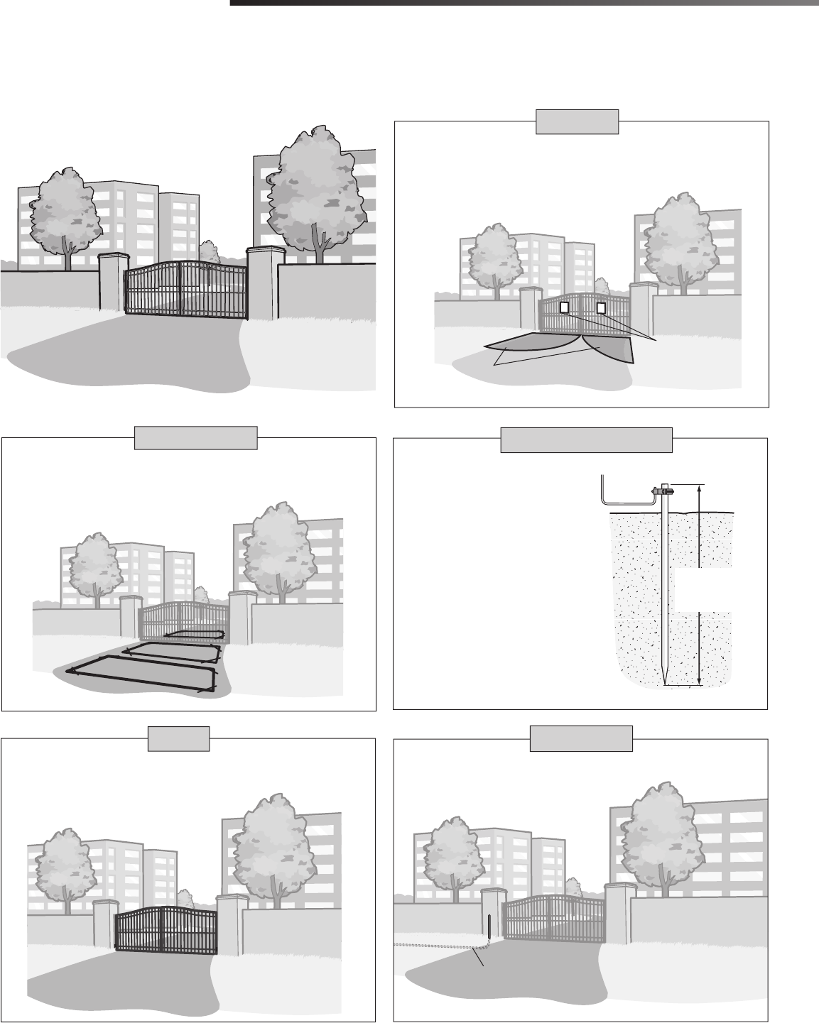
PREPARATION
VEHICLE LOOPS
The vehicle loops allow the gate to stay open when vehicles are obstructing the
gate path. Suggested for vehicles 14 feet (4.27 m) or longer. Vehicle loops are
not required but are recommended.
!
!
Entrapment protection devices are required to protect against any entrapment
or safety conditions encountered in your gate application (refer to page 5 for
more details). Install warning signs on both sides of the gate.
Gate must be constructed and installed according to ASTM F2200 standards
(refer to page 4). Gate must fit specifications of operator (refer to
specifications).
Proper grounding gives an electrical
charge, such as from an electrical
static discharge or a near lightning
strike, a path from which to dissipate
its energy safely into the earth.
Without this path, the intense energy
generated by lightning could be
directed towards the gate operator.
Although nothing can absorb the
tremendous power of a direct lightning
strike, proper grounding can protect
the gate operator in most cases.
(Inside Property)
Entrapment Danger
Warning Signs
Check national and local
codes for proper depth
SAFETY
GATE
EARTH GROUND ROD
SITE PREPARATION
Check the national and local building codes BEFORE installation.
Conduit must be UL approved for low and high voltage.
CONDUIT
Conduit
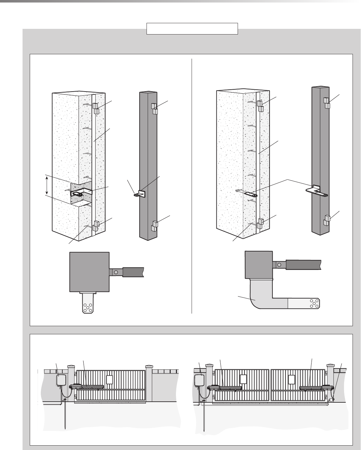
11
SITE PREPARATION
INSTALLATION TYPES
PULL-TO-OPEN PUSH-TO-OPEN
Top View
Heavy Steel Plate for
Reinforcement (Not provided)
Back Steel Bracket
(Reinforce if necessary)
NOTE: Weld Re Bar
Behind Gate Hinges for
Maximum Strength.
Gate Hinge
Top View
10"
Minimum
Heavy Steel
Bracket
(Reinforce if
necessary) Back Steel Plates
for Reinforcement
(Not provided)
SINGLE GATE
!!!
DUAL GATE
Water Tight Conduit (Not provided) Shielded low
voltage wires.
Earth Ground Rod
Primary Operator Secondary Operator Junction Box
Control Box
Control Box
Earth Ground Rod
Operator
Water Tight Conduit
(Not provided)
Identify your installation type. The installation steps in this manual will show a typical Pull-to-Open application.
Gate Hinge
Gate Hinge
Gate Hinge Gate Hinge
Gate Hinge
Gate Hinge
Gate Hinge
Heavy Steel Plate
for Reinforcement
(Not provided)
Back Steel
Bracket
(Reinforce if
necessary)
Heavy Steel Plate
for Reinforcement
(Not provided)
Post Install
Column Install Post Install
Column Install
NOTE: Weld Re Bar
Behind Gate Hinges for
Maximum Strength.
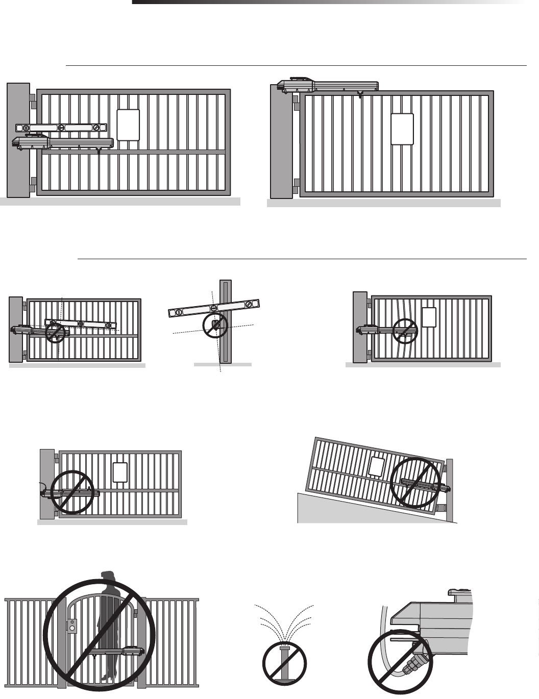
12
MOUNTING OPTIONS
PREPARATION
!
!!
!
!
DO NOT weld the crossbar on just a few pickets, or they could bend.
An off-level installation may cause the gate or operator to fail prematurely.
The operator can be mounted on top of the gate frame.
MOUNTING OPTIONS
DO NOT install upside down.
DO NOT install on ANY pedestrian passageways, doorways, or gates.
DO NOT install on uphill or downhill gates.
DO NOT install next to sprinklers
or any area that may expose
the bottom of operator to water. DO NOT over-bend the cord from the operator.
Doing this will cause the wires to eventually break.
Weld a horizontal bar across entire gate on any installation for strength.
Make sure that the operator is mounted level or it will not function properly.
MOUNTING DOs
MOUNTING DON'Ts
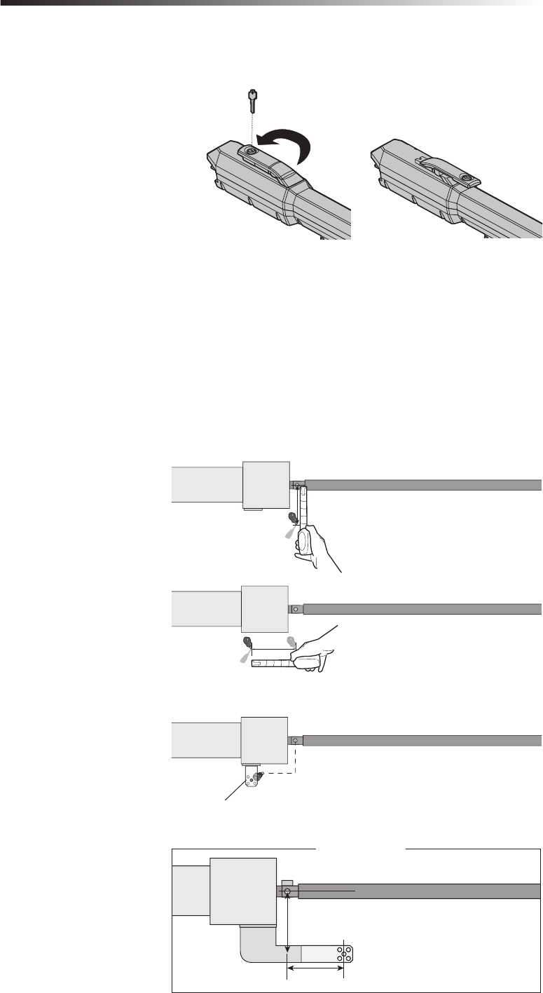
13
MANUAL RELEASE + DETERMINE THE POSITION OF THE POST BRACKET
INSTALLATION
MANUAL RELEASE
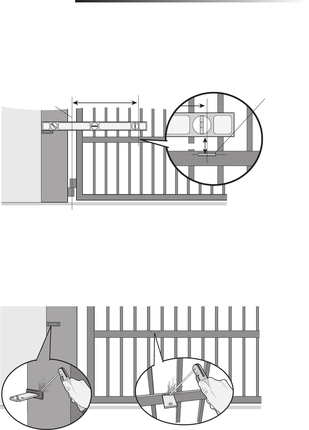
DETERMINE THE POSITION OF THE POST BRACKET
Insert the key into the lock and turn it 180 degrees counterclockwise.
Turn the release lever 180 degrees counterclockwise. The operator is now in
manual mode.
1
2
Close the gate.
Choose a vertical mounting location for the post bracket.
Place a measuring tape under the center of the gate hinge point and measure
out 7.75 inches.
Use a screwdriver or dowel rod to temporarily mark the location of the first
measurement.
Measure 8.5 inches from the previous mark.
Use a screwdriver to mark the location of the second measurement.
Align the post bracket as close as possible above the screwdriver or dowel rod
and tack weld the post bracket in the desired vertical position.
1
2
3
4
5
6
7
7.75"
8.5"
7.75"
8.5"
Post Bracket Location
If this operator is a replacement for a Miracle-One™ operator, use the existing post bracket and gate bracket. Remove the Miracle-One™ operator
from the brackets and proceed to page 15.
7.75"
8.5"
PUSH-TO-OPEN
If your application is Push-to-Open, refer to the illustration to the right.
14
DETERMINE THE POSITION OF THE GATE BRACKET + WELD THE BRACKETS
INSTALLATION
DETERMINE THE POSITION OF THE GATE BRACKET
WELD THE BRACKETS
Position the operator on the brackets and make sure the operator is level and
positioned correctly on the gate.
Remove the operator from the gate.
Completely weld around the post bracket and gate bracket.
1
2
The gate bracket MUST be installed in an area that can withstand heavy forces.
Additional reinforcement steel plates may be necessary for mounting.
Position a level on the post bracket and measure 27.75 inches over from the
gate hinge point and mark the location on the gate.
Measure 2.25 inches down from the previous mark and tack weld the gate
bracket in this position.
1
2
3
27.75"
2.25"
Gate Bracket Location
Gate Hinge Point
15
ATTACH THE OPERATOR TO THE BRACKETS
INSTALLATION
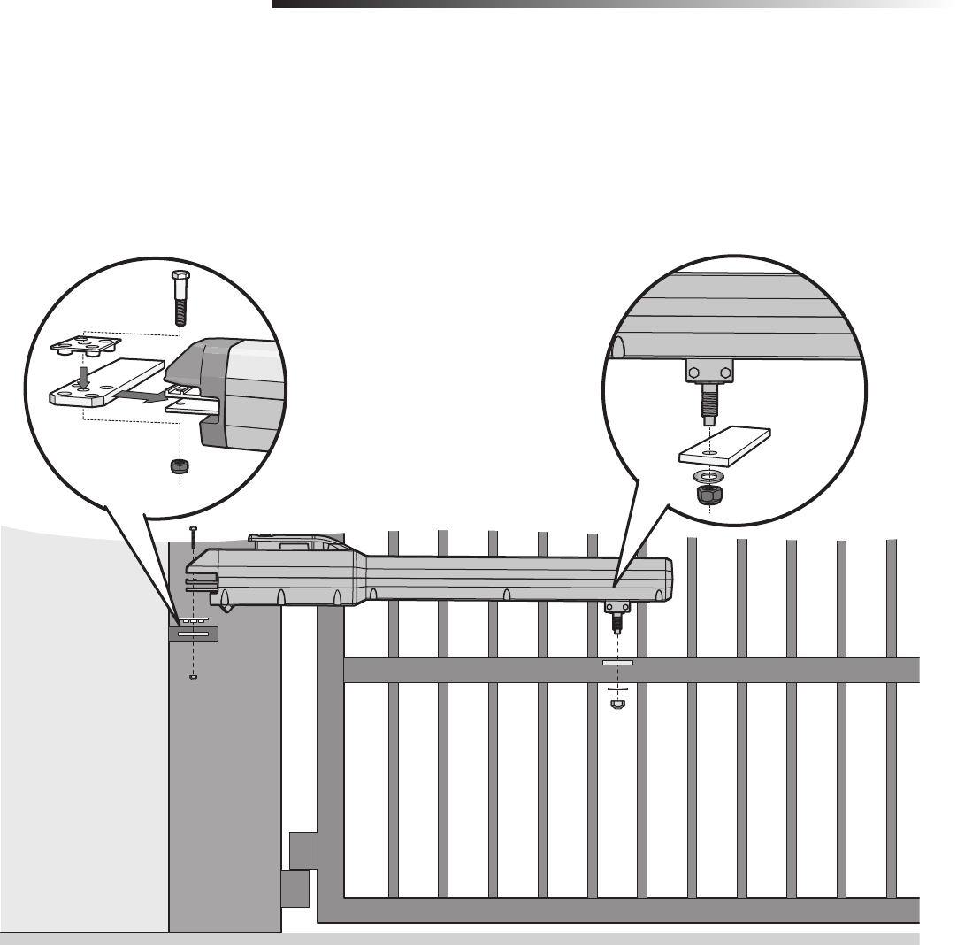
ATTACH THE OPERATOR TO THE BRACKETS
Attach the operator to the post bracket with the bolt, mounting plate, and nut
as shown.
Attach the operator to the gate bracket with the bolt, washer, and nut as shown.
Tighten the nut until it reaches the bottom of the gate bracket, then turn the
nut a half turn, making sure not to overtighten.
1
2
Post Bracket
Gate Bracket
For dual gate applications, repeat the previous installation steps to install the second operator.
16
STANDARD CONTROL BOX
INSTALLATION
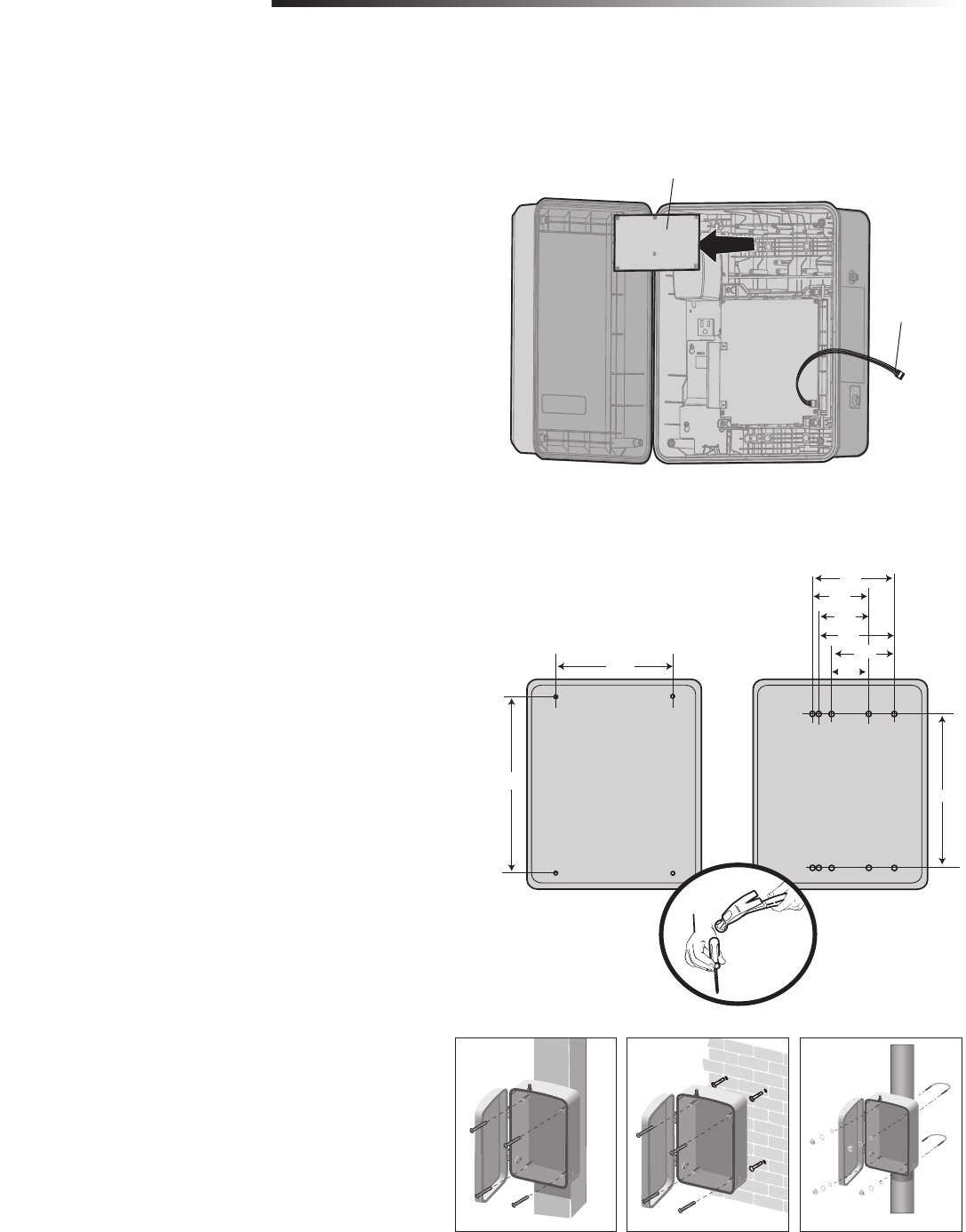
STANDARD CONTROL BOX
For Large Metal Control Box installation, refer to the following page.
ABC
MOUNT THE CONTROL BOX
The control box MUST be mounted within 5 feet (1.52 m) of the gate operator.
Mount the control box as high as possible for best radio reception. Make sure the
control box is level.
Remove the screws and open the control box.
Disconnect the connector labeled "Main Board" on the expansion board.
Remove the expansion board by removing the screws.
Select the mounting holes and remove the knockouts using a screwdriver and
hammer.
Secure the control box to mounting surface.
A. Column: Use the provided screws (4).
B. Wall: Use the provided screws (4).
C. Post: Use U-bolts and rubber washers (not provided) to ensure a watertight
seal. Make sure the U-bolts do not protrude more than 3/4 inch from the
control box because this can short the control board.
Reinstall the expansion board and connect the "Main Board" connector to the
expansion board.
1
2
3
4
5
6
"Main Board" Connector
Expansion Board
WALL OR COLUMN MOUNT
POST MOUNT
13.75"
9.13"
6.36"
4.38"
5.88"
3.88"
4.88"
2.88"
12.06"
17
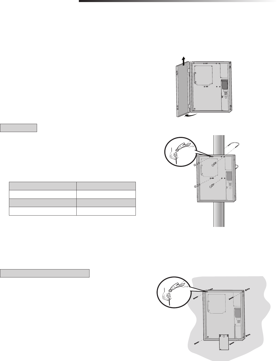
The control box can be mounted to a post with 'U' bolts (refer to chart). The
knock out will accommodate a 3/8" diameter 'U' bolt. Select center mounting
holes (top and bottom) and knock out using a screwdriver and hammer.
Secure the control box to mounting surface with U-bolts and rubber washers
(not provided) to ensure a watertight seal.
LARGE METAL CONTROL BOX (XLM)
INSTALLATION
LARGE METAL CONTROL BOX (XLM)
Open the control box. The control box door may be removed by opening the
door 90°. Lift the door from the hinges and set aside until the installation is
complete.
1
2
2
1
3
2
Remove the electrical outlet cover by loosening the screws and sliding the
cover up.
Use knock outs located at the 4 corners of the control box and knock out using
a screwdriver and hammer.
Secure the control box to mounting surface using the provided screws (4).
TYPE AND SIZE 'U' BOLT OPENING
Standard 3" Round Pipe 3-1/2"
Standard 4" Square Post 4"
Standard 6" Square Post 6"
3
MOUNT THE CONTROL BOX (XLM)
The control box MUST be mounted within 5 feet (1.52 m) of the gate operator. Mount the control box as high as possible for best radio reception. Make sure the control box
is level.
POST MOUNT
WALL OR COLUMN MOUNT
3
4
90°
3
2
4
18
SET PEN SET CL SE
M E
GATE
FF
5
10
60
180 M N M X
E N S
FF N
CL SE ST P
INPUT POWER
ATT CHARGING
T MER
ATE MO ING
ATT LOW
ACC PWR O L
AGNOSTIC
CO ES
STATUS:
“FIRE
EPT ”
OPEN
XIT
SHADOW
CLOSE
EYES/
NTERRUPT
LOCK
N.O. N C.
+ -
+ -
ACCESSORY
POWER
ON SW.
EXP.
BOAR
RESS &
REL ASE
TO BEG N
ETUP
LA S 2 U P Y
4 V L S
1
LMT
2
- + + -
J5
+
SOLAR /
CHARGER
J15
+ -
BATT - +
DC
POWER
ID RESET ALARM
GROUND
BR GRN WT YE BLU RED BR GRN WT YE BLU RED
SHADOW
CLOSE
EYES/
INTERRUPT
- + + -
WIRE THE ENTRAPMENT PROTECTION DEVICES + EARTH GROUND ROD
WIRING
To prevent SERIOUS INJURY or DEATH from a moving gate:
• Entrapment protection devices MUST be installed to protect anyone who may
come near a moving gate.
• Locate entrapment protection devices to protect in BOTH the open and close
gate cycles.
• Locate entrapment protection devices to protect between moving gate and
RIGID objects, such as posts or walls.
WIRE THE ENTRAPMENT PROTECTION DEVICES
Entrapment protection devices are required. Refer to page 5 for more information regarding application.
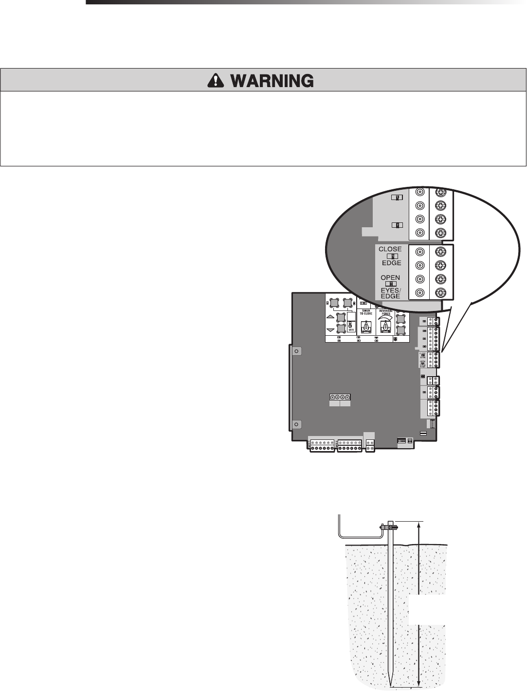
EARTH GROUND ROD
Use the proper earth ground rod for your local area. The ground wire must be a
single, whole piece of wire. Never splice two wires for the ground wire. If you should
cut the ground wire too short, break it, or destroy its integrity, replace it with a single
wire length.
Install the earth ground rod within 3 feet of the control box.
Run wire from the earth ground rod to the control box.
NOTE: If the operator is not grounded properly the range of the remote controls will
be reduced.
1
2
Check national and local
codes for proper depth
To Control Box
Connect the entrapment protection device to the EYES EDGE terminal on the
control board. These inputs are for pulsed photoelectric sensors and dry contact
edges.
• Close Photoelectric Sensor Entrapment Protection: Connect wires from the
photoelectric sensors to the Inputs on the CLOSE EYES/INTERRUPT terminal.
• Close Edge Entrapment Protection: Connect wires from the entrapment
protection device to the Inputs on the CLOSE EDGE terminal.
• Open Entrapment Protection: Connect wires from the entrapment protection
device to the Inputs on the OPEN EYES/EDGE terminal.
NOTE: Refer to the “Accessory Features on the Control Board” section on
page 31.
1
TO ERASE LEARNED MONITORED PHOTOELECTRIC
SENSORS
1 Remove the photoelectric sensor wires from the terminal block.
2 Press the SET OPEN and SET CLOSE buttons simultaneously until the SET OPEN
and SET CLOSE LEDs turn on.
3 Press both SET OPEN and SET CLOSE buttons again to turn off the SET OPEN
and SET CLOSE LEDs.
NOTE: For dual gate applications repeat the steps above on the other operator.