Chamberlain Group The 7545 Linear gate operator w/ 900MHz FHSS transceiver User Manual Part 2
Chamberlain Group Inc, The Linear gate operator w/ 900MHz FHSS transceiver Part 2
Contents
- 1. User Manual Part 1
- 2. User Manual Part 2
User Manual Part 2
19
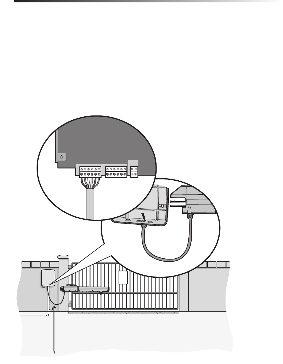
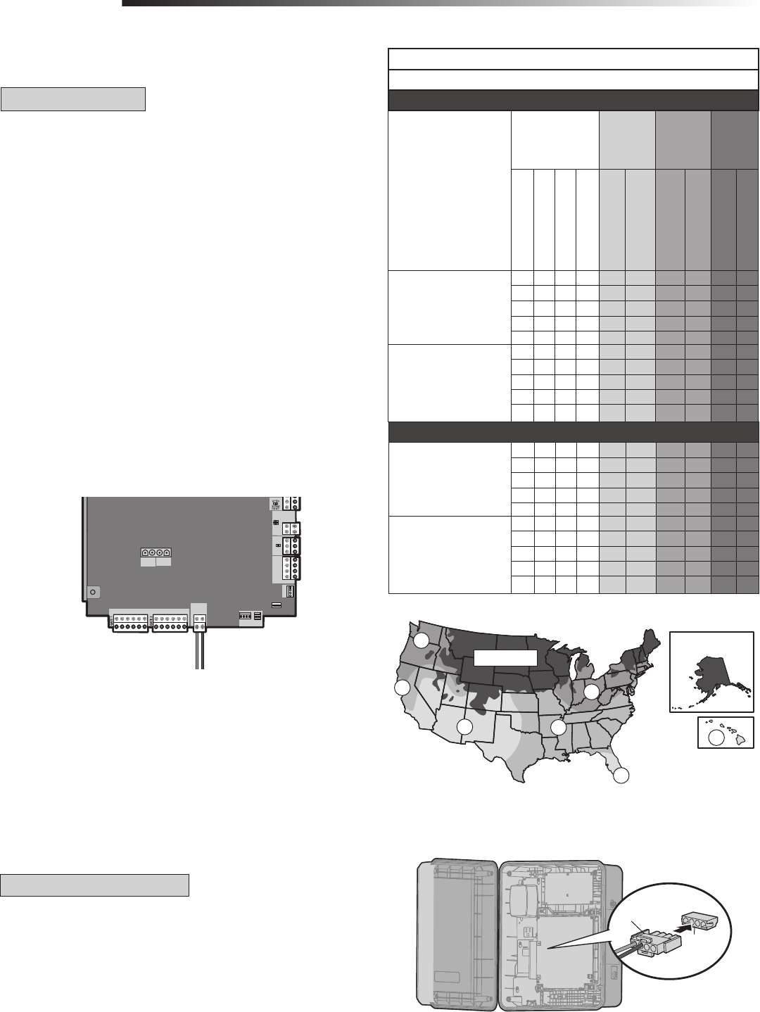
Insert the operator cable through the watertight connector mounted in the
bottom of the control box.
Extend the operator cable and wires to the Gate 1 connector and connect
as shown.
Tighten watertight connector nut.
WIRE THE OPERATOR ARM TO THE CONTROL BOARD
1
2
3
If installing one operator, proceed to page 22. If installing two operators, continue to the next page.
WIRE THE OPERATOR TO THE CONTROL BOARD
WIRING
!
GATE 1
BR GRN WHT YEL BLU RE
GATE 2
BR RN WHT YEL BLU RE
+ -
S LAR /
HARGER
20
DUAL GATES ONLY
DUAL GATES ONLY
WIRING
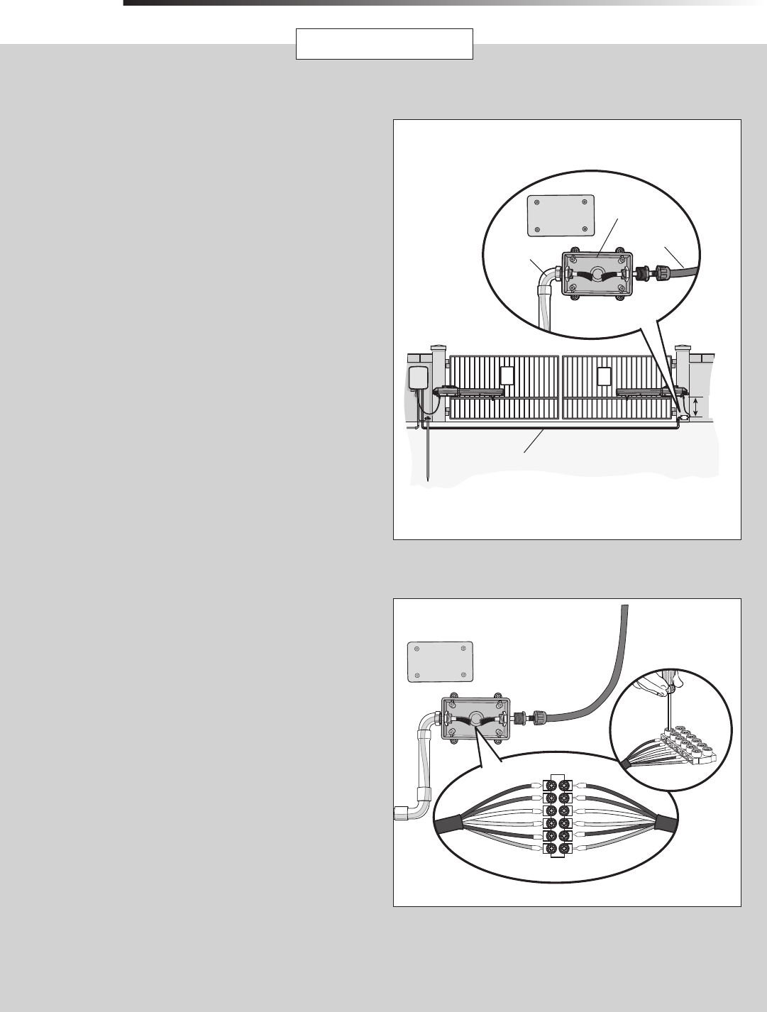
Before digging, contact local underground utility locating companies. The
following items are required to complete the junction box installation:
• 4 x 4 Junction Box with 3/4" NPT threaded port holes
• Screws
• PVC Conduit
Trench across driveway to bury the extension cable. Use PVC conduit to
prevent damage to cables.
Open the junction box by removing screws (4) and set aside.
Mount the junction box within 3 feet (0.9 m) of second operator.
Route operator cable and extension cable through watertight connector
nut and watertight connector.
Insert cables and watertight connectors into the holes in the bottom of the
junction box (not provided).
Feed extension cable through PVC conduit and secure with nut.
INSTALL THE EXTENSION CABLE AND JUNCTION BOX
1
2
4
5
6
3
!!
PVC Conduit
Junction Box
Extension Cable
Operator Cable
Within
3 feet
Insert wires from extension cable and operator cable into the terminal
block connector as shown (like-colored wires must face each other).
Put wires inside of junction box.
Secure operator and extension cables with watertight connector nut.
Reinstall cover.
1
2
3
4
WIRE THE EXTENSION CABLE TO THE SECONDARY OPERATOR
Terminal Block Connector
Extension Cable Operator Cable
21
DUAL GATES ONLY
WIRING
DUAL GATES ONLY
SET OPEN SET C OSE
MO E
G TE
F
5
10
0
80
( E ON S)
O F ON
OSE STOP
NP T POWER
B TT C ARGNG
MER
ATE M V NG
B TT L W
ACC WR VL
I GNOS I
CO ES
STATUS
EX T
S AD W
C OSE
E
NTE RUP
LOCK
NO
M
NC
+
+
AC ESS RY
OWER
ON SW
XP
B ARD
M T ER
R S &
L A E
T BG N
MIT
2
+ +
J5
+
OL R /
HAR ER
15
+
A T +
DC
POW R
ID R SET AL RM
BR GRN WT E B U ED BR GRN WT E LU R D
LOSE
OFF ON
BIPART
DELAY
L
TIMER
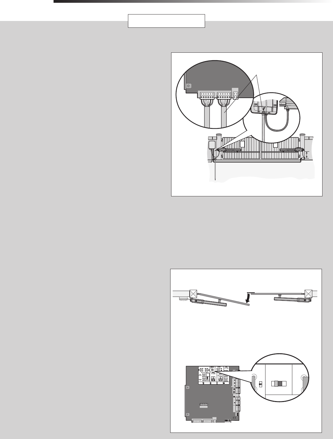
SET THE BIPART DELAY
Occasionally in dual gate installations, one gate will need to open first and close
second. This would happen if there was an ornamental overhang on one gate or
if using a solenoid lock, for example. This gate is called the Primary gate and
needs to be connected to Gate 1 connections on the control board. Thus, it is
preferred that the control box be installed on the same side as this gate. If
there is no appropriate location on that side for the control box, then mount the
control box on the opposite side, but connect the operator closest to the control
box to the Gate 2 connector and the operator on the opposite side to the Gate 1
connector.
NOTE: The gate with the longer travel span (opening) must be set as the
primary gate (GATE 1).
The BIPART DELAY switch on the control board needs to be set to the ON
position.
The following illustration shows a dual gate configuration with a decorative
overlapping piece on the outside of the gate.
If a solenoid lock is being used on a gate, the gate with the lock attached to it
is the primary gate.
Primary Gate - Connect to Gate 1 Connector on Control Board.
Primary Gate
OUTSIDE PROPERTY
1
Choose a knockout in the bottom of the control box.
Insert a watertight connector through the knockout and tighten with nut.
Insert the extension cable through watertight connector.
Extend the cable and wires to Gate 2 connector on the control board.
Connect wires as shown.
Tighten the watertight connector nut to secure extension cable to control
box.
1
2
3
WIRE THE EXTENSION CABLE TO THE CONTROL BOARD
!!
GATE 1
BRO GRN HT YEL BLU RED
GATE 2
BRO GRN WHT YEL BLU RED
+
SOLAR /
CHARGER
Extension Cable
4
5
22
POWER WIRING
WIRING
POWER WIRING
This operator can be wired for either 120 Vac or a solar panel (not
provided). Follow the directions according to your application. For dual
gate applications, power will have to be connected to each operator.
Main power supply and control wiring MUST be run in separate
conduits.
AMERICAN WIRE
GAUGE (AWG)
MAXIMUM WIRE
LENGTH (120 VAC)
MAXIMUM WIRE
LENGTH (240 VAC)
14 130 feet 260 feet
12 205 feet 410 feet
10 325 feet 650 feet
8 520 feet 1040 feet
6 825 feet 1650 feet
4 1312 feet 2624 feet
NUMBER OF CYCLES PER DAY
Swing Gate Installation (6 ft. 1200 lb. gate/ 19 ft. 500 lb. gate)
CONFIGURATION SINGLE GATE DUAL GATE
Solenoid Lock
50 mA
100 mA
300 mA
7AH
Batteries
(standard)
33AH Batteries
(optional for
Large Metal
Control Box)
7AH
Batteries
(standard)
33AH Batteries
(optional for
Large Metal
Control Box)
TOROID
POWERED
Continuous Continuous Continuous Continuous
✔Continuous Continuous 2059 2056
✔Continuous Continuous Continuous Continuous
✔Continuous Continuous Continuous Continuous
✔Continuous Continuous Continuous Continuous
BATTERY
POWERED
215 1202 98 612
✔122 763 71 443
✔207 1292 96 600
✔200 1249 94 590
✔178 1111 88 554
TRANSFORMER
POWERED
1726 1720 1347 1340
✔1359 1352 1147 1140
✔1670 1663 1301 1293
✔1615 1607 1257 1248
✔1391 1380 1075 1064
120 VAC
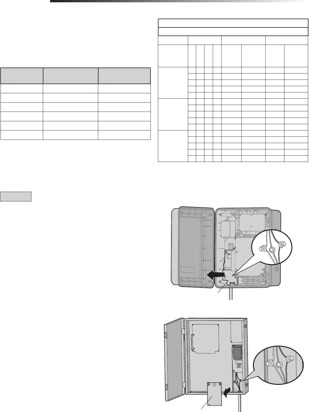
Turn off the AC power from the main power source circuit breaker.
Run the AC power wires to the control box.
Remove the junction box cover.
Connect the green wire to the earth ground rod wire using a wire nut.
Connect the white wire to NEUTRAL using a wire nut.
Connect the black wire to HOT using a wire nut.
Replace the junction box cover. Ensure the wires are not pinched.
1
2
3
4
5
6
7
NOTE: Use copper conductors ONLY.
Junction
Box Cover
Junction
Box Cover
STANDARD CONTROL BOX
LARGE METAL CONTROL BOX (XLM)
23
POWER WIRING CONTINUED...
POWER WIRING + CONNECT BATTERIES
WIRING
NOT PROVIDED. SEE ACCESSORIES.
The solar panel(s) must be located in an open area clear of obstructions and shading
for the entire day. The gate operator is not supported in northern climates where
temperatures reach below -4˚F. This is due to cold weather and a reduced number of
hours of sunlight during the winter months. Cycle rate may vary from solar chart for
areas that reach below 32˚F. Solar panels should be cleaned on a regular basis for
best performance to ensure proper operation. For solar applications, a minimum of
two 10W solar panels in series and two 7AH batteries are recommended. For Zone 3
cold weather sites, two 33AH batteries are recommended (for Large Metal Control
Box (XLM) ONLY). We recommend LiftMaster low power draw accessories to minimize
power draw, refer to accessory page.
SOLAR PANEL(S)
NOT AVAILABLE
NOT AVAILABLE
11
1
2
3
3
2
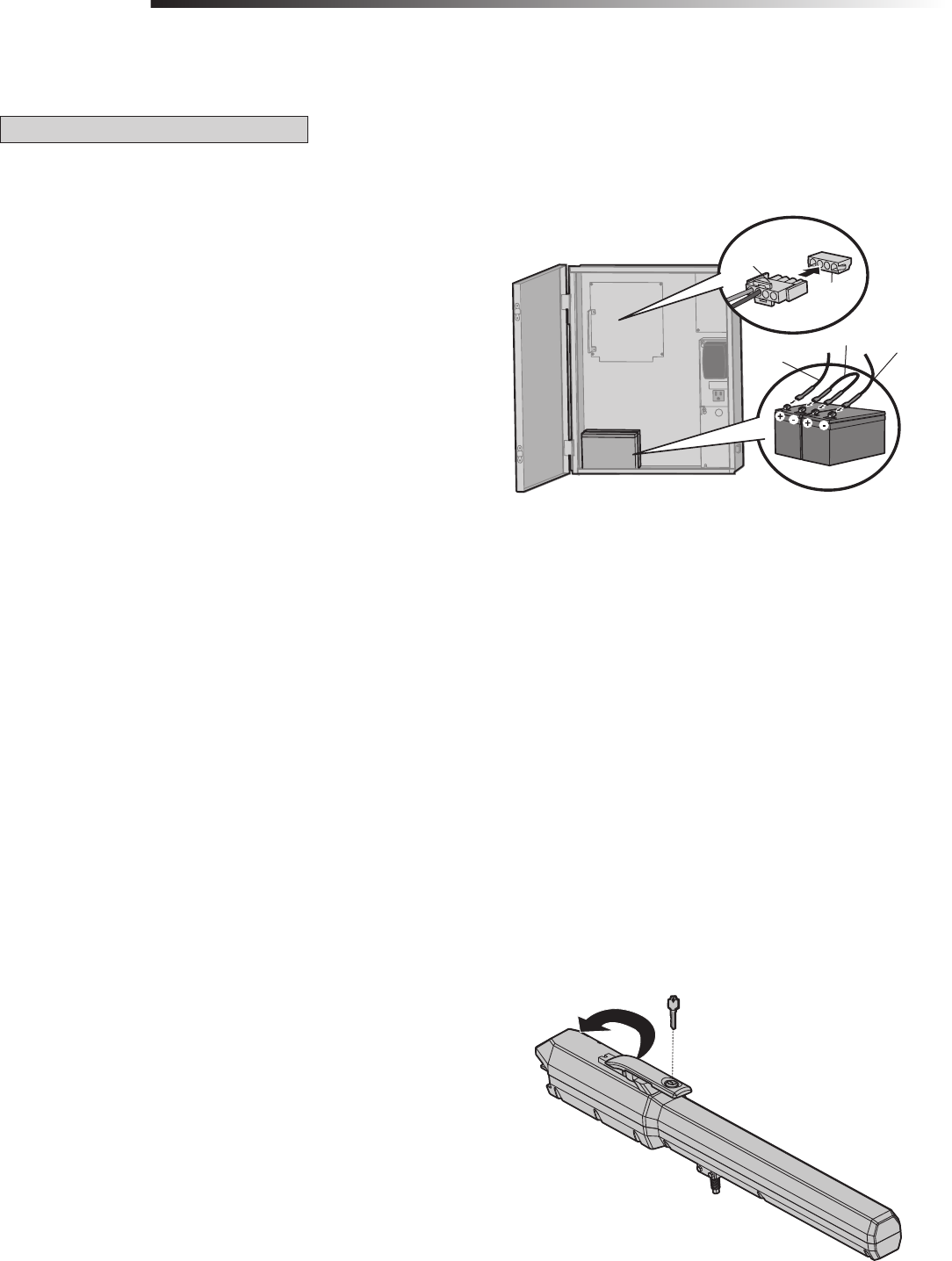
Locate the solar/charge plug on the control board and remove the transformer
wires from the plug.
Connect the red (+) wire from the solar panel to the solar/charge plug (+).
Connect the black (-) wire from the solar panel to the solar/charge plug (-).
Plug in the solar/charge plug.
1
2
3
NUMBER OF CYCLES PER DAY (SOLAR)
Swing Gate Installation (6 ft. 1200 lb. gate/19 ft. 500 lb.)
Single Gate
CONFIGURATION ZONE 1
(6 Hrs
sunlight/day)
ZONE 2
(4 Hrs
Sunlight/day)
ZONE 3
(2 Hrs
Sunlight/
day)
Low Band
High Band
Expansion Board
1 Loop (LD7LP)
7AH Batteries (standard)
33AH Batteries (optional)
7AH Batteries (standard)
33AH Batteries (optional)
7AH Batteries (standard)
33AH Batteries (optional)
20W SOLAR PANEL
NOTE: 20W would be two 10W
(12V) panels in series.
120 154 76 96 33 38
✔117 151 74 93 30 35
✔✔ 111 144 68 87 25 29
✔✔109 142 66 84 23 27
✔✔✔✔ 99 131 56 74 13 17
40W SOLAR PANEL
NOTE: 40W would be two 20W
panels in series.
156 202 101 128 45 54
✔154 199 98 125 42 51
✔✔ 148 193 92 119 37 45
✔✔145 190 90 117 35 43
✔✔✔✔135 179 80 106 25 33
4
LOCK
+ -
ACCESSORY
POWER
ON SW.
EXP.
BOAR
CL S 2 S PP Y
24 OTS
- +
J5
+
SOLAR /
CHARGER
J15
+ -
BATT - +
DC
POWER
ID RESET ALARM
GROUND
BR GRN WT YE BLU RED BR GRN WT YE BLU RED
Red
Black
(to solar panel)
Turn OFF AC power to the operator at the circuit breaker.
Plug the battery connector to the J15 plug labeled BATT(-)(+) DC(-)(+) on the
control board. The control board will power up.
Turn ON AC power to the operator.
CONNECT BATTERIES
The batteries are charged in the circuit by the transformer or solar panel.
1
2
3
STANDARD CONTROL BOX
Battery
Connector
J15 Plug
Dual Gates
20W SOLAR PANEL
NOTE: 20W would be two 10W
(12V) panels in series.
54 69 34 43 15 17
✔53 68 33 42 13 16
✔✔ 50 65 31 39 11 13
✔✔ 49 64 30 38 10 12
✔✔✔✔ 45 60 25 33 6 7
40W SOLAR PANEL
NOTE: 40W would be two 20W
panels in series.
71 92 46 58 20 24
✔70 90 44 57 19 23
✔✔ 67 87 42 54 16 20
✔✔ 66 86 41 53 16 19
✔✔✔✔ 62 81 36 48 11 15
24
7AH BATTERIES
Turn OFF AC power to the operator at the circuit breaker and unplug the
transformer.
Unplug the battery connector to the J15 plug labeled BATT(-)(+) DC(-)(+) on
the control board by squeezing the plug and pulling it from the control board.
Connect a jumper between the positive (+) terminal of one battery to the
negative (-) terminal of the other battery.
Connect the red wire from the J15 plug labeled BATT (+) to the positive (+)
terminal of the battery.
Connect the black wire from the J15 plug labeled BATT (-) to the negative (-)
terminal of the battery.
Plug the J15 plug into the control board. The control board will power up.
Plug the transformer in.
Turn ON AC power.
1
2
3
4
5
CONNECT BATTERIES + ENGAGE THE OPERATOR
WIRING
ENGAGE THE OPERATOR
Turn the release lever clockwise 180°. This engages the motor.
Turn the key clockwise 180°. This locks the release lever.
The operator is now engaged.
1
2
LARGE METAL CONTROL BOX (XLM)
6
7
8
Battery
Connector
J15 Plug
Jumper
Black Wire
Red Wire
CONNECT BATTERIES
The batteries are charged in the circuit by the transformer or solar panel.
33AH BATTERIES
33AH batteries can be used in place of the 7AH batteries for a Large Metal Control
Box (XLM) solar application ONLY. A wall or column mount installation is
recommended when using the 33AH batteries.
25
OPEN limit
CLOSE limit
!
SET OPEN SET CLOSE
MOVE
GATE
OF
5
10
60
80
S
OFF ON
OPEN C OSE STOP
NPUT POWER
ATT CHARGNG G TE MOV NG
ATT LOW
CC PWR OVL
D AGNOST
CODES
STATUS
IRE
DEPT
SH DOW
CLO E
INT RR
OCK
N O NC
+
+
CCESSORY
POWER
N SW
EXP
OARD
T R
ORK
R L A E
O B GN
S TUP
1
L MIT
2
+
J5
+
SOLAR /
CHARGER
15
+
B TT +
DC
POWER
G OUND
R GRN WT E BLU R D R GRN WT YE BLU ED
SET OPEN SET CLOSE
OFF
BI
DEL
PRESS &
RELEASE
TO BEG
MOVE
GATE
INPU
TUS:
P
REL
TO BE
SETUP
1
GAT
LIMI
2
SET OPEN SET CLOSE
OFF
BIP
DEL
PRESS &
RELEASE
TO BEG
MOVE
GATE
INPU
US:
PR
REL
TO BEG
SETUP
1
GAT
LIMI
2
SET OPEN SET CLOSE
O
OFF
5
10
(SECOND
O
INPUT POWER
ARGIN
TIM
TI
TO CL
PRESS &
RELEASE
TO BEG N
SETUP
1
GATE
LIMIT
2
3
12
4
5
LIMIT AND FORCE ADJUSTMENT
ADJUSTMENT
6
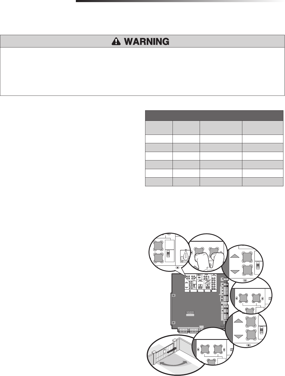
To reduce the risk of SEVERE INJURY or DEATH:
• Without a properly installed safety reversal system, persons (particularly small
children) could be SERIOUSLY INJURED or KILLED by a moving gate.
• Too much force on gate will interfere with proper operation of safety reversal
system.
• NEVER increase force beyond minimum amount required to move gate.
• NEVER use force adjustments to compensate for a binding or sticking gate.
• If one control (force or travel limits) is adjusted, the other control may also
need adjustment.
• After ANY adjustments are made, the safety reversal system MUST be tested.
Gate MUST reverse on contact with a rigid object.
LIMIT SETUP LEDS
SET OPEN
LED
SET CLOSE
LED
OPERATOR MODE EXPLANATION
BLINKING BLINKING NORMAL MODE Limits are not set.
OFF OFF NORMAL MODE Limits are set.
BLINKING BLINKING LIMIT SETTING MODE Limits are not set.
BLINKING ON LIMIT SETTING MODE Open limit is not set.
ON BLINKING LIMIT SETTING MODE Close limit is not set.
ON ON LIMIT SETTING MODE Limits are set.
LIMIT AND FORCE ADJUSTMENT
INTRODUCTION
Your operator is designed with electronic controls to make travel limit and force
adjustments easy. The adjustments allow you to program where the gate will stop in
the open and close position. The electronic controls sense the amount of force
required to open and close the gate. The force is adjusted automatically when you
program the limits but should be fine tuned using the REVERSAL FORCE dial on the
control board (refer to Fine Tune the Force section) to compensate for environmental
changes.
The limits can be set using the control board (below) or a remote control (refer to
Limit Setup with a Remote Control in the Additional Features section). Setting the
limits with a remote control requires a 3-button remote control programmed to
OPEN, CLOSE, and STOP.
4
When limits are set properly the operator will automatically exit limit setting mode.
DUAL GATES: Set the GATE switch to the 2 position and repeat steps 2-7 for the
secondary gate.
1
2
5
3
For dual gate applications the limits will have to be set for each
operator. The gate MUST be attached to the operator before setting the
limits and force.
Set the GATE switch to the 1 position.
Press and release the SET OPEN and SET CLOSE buttons simultaneously to enter
limit setting mode.
Press and hold the MOVE GATE buttons to move the gate to the open or close
limit.
Press and release the SET CLOSE or SET OPEN button depending on which limit
is being set.
Press and hold the MOVE GATE button to move the gate to the other limit.
Press and release the SET CLOSE or SET OPEN button depending on which limit
is being set.
Cycle the gate open and close. This automatically sets the force.
INITIAL LIMITS AND FORCE ADJUSTMENT
6
7
7
26
!
OPEN limit
CLOSE limit
!
S T O EN S T LOSE
MOVE
GATE
FF
5
10
6
18 M N M
S C N S)
O F ON
A T C AR I G A E M V NG
A C PWR O L
T
S ATUS
H
C OS
Y S
C Y
P WER
N W
EXP
OA D
X I ER
N T O K
S
O
S
1
MT
2
5
OL R /
C A GER
15
B TT
DC
OW R
D R S T L RM
BR G N WT E LU R D BR G N WT YE B U ED
60
MIN MAX
BATT LOW
WR
REVERSAL
FORCE
NETWORK
OPEN CLOSE STOP
TEST
BUTTONS
RSAL
CE
TTER
TWORK
2
1
3
2
LIMIT AND FORCE ADJUSTMENT + OBSTRUCTION TEST
ADJUSTMENT
S T O EN ET L SE
OVE
A E 5
0
FF O
P N C O E TP
N UT O ER
B T C A G N
I ER
A E M V G
A T OW
CC WR V
A N S I
O ES
S AT S
I E
H
O E
T R
O
W
O W
O
O AR /
H RG R
J 5
TT
WER
BR R WT E B U ED BR N WT E B U ED
OPEN CLOSE STOP
TEST
BUTTONS
RSAL
CE
TTER
ETWORK
1
MOVE
GATE
0
I
FF N
OPEN CLO E STOP
P T PO ER
TT HA GN AT MO I G
A T OW
CC WR O L
I GN S I
C DES
S ATUS
S C
FRE
S
L SE
EE/
I T RR
O
A CE S RY
P WER
ON SW
XP
ER
K
LMT
2
5
SO AR /
CH R ER
5
B TT
C
OW R
D R S T L RM
R UND
SET OPEN SET CLOSE
F
B
D
FINE TUNE THE FORCE
The FORCE DIAL on the control board is used for fine tuning the force in cases where
wind or environmental changes may affect the gate travel.
Based on the length and weight of the gate it may be necessary to make additional
force adjustments. The force setting should be high enough that the gate will not
reverse by itself nor cause nuisance interruptions, but low enough to prevent serious
injury to a person. The force setting is the same for both the open and close gate
directions.
Open and close the gate with the TEST BUTTONS.
If the gate stops or reverses before reaching the fully open or closed position,
increase the force by turning the force control slightly clockwise.
Perform the “Obstruction Test” after every force setting adjustment (see
below).
OBSTRUCTION TEST
The operator is equipped with an automatic obstruction sensing feature. If the gate
encounters an obstruction during motion, the operator will automatically reverse
direction of the gate for a short time and then stop the gate. After any adjustments
are made, test the operator:
Open and close the gate with the TEST BUTTONS, ensuring that the gate is
stopping at the proper open and close limit positions.
Place a solid object between the open gate and a rigid structure. Ensure that
the gate, the solid object, and the rigid structure can withstand the forces
generated during this obstruction test.
Run the gate in the close direction. The gate should stop and reverse upon
contact with the solid object. If the gate does not reverse off the solid object,
reduce the force setting by turning the force control slightly counter-clockwise.
The gate should have enough force to reach both the open and close limits, but
MUST reverse after contact with a solid object.
Repeat the test for the open direction.
1
2
3
4
1
2
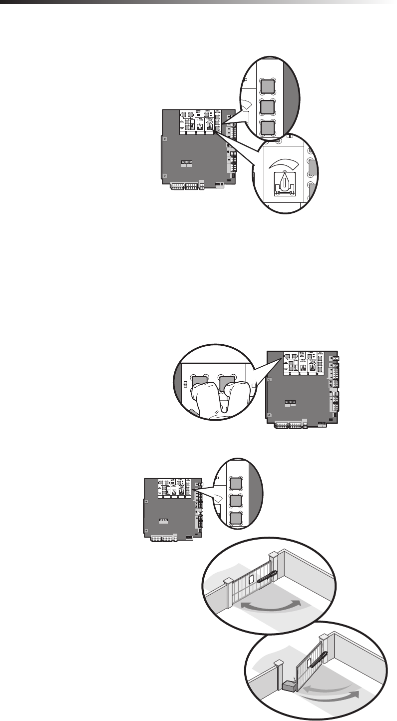
ADJUST THE LIMITS
If the limits have already been set the operator will exit the limit setting mode after
resetting each limit. Each limit is set separately by following steps 1-3 of the Initial
Limit and Force Adjustment section.
ERASE LIMITS
To erase the limits, press and hold the SET OPEN and SET CLOSE buttons
simultaneously (5 seconds) until both the SET OPEN and SET CLOSE LEDs blink
rapidly and the operator beeps.
Release the buttons and the SET OPEN and SET CLOSE LEDs will blink slowly
indicating the limits will need to be set.
1
2
3
27
ET OP N S T CLO E
MO E
G TE
O F
5
0
6
1 0 M N M X
OFF ON
NLO E ST P
A T HA G NG A E MO NG
CC P R O L C DES
TA US
I E
E T
OP
H D W
C OS
NT R
OC
C Y
OW R
N W
XP
B A D
M T R
TW R
S UP
LMT
2
5
S L R /
C A GER
J 5
B TT
DC
OW R
D R S T L RM
G OU D
R G N WT E U ED BR G N WT E L R D
OPEN CLOSE STOP
TEST
BUTTONS
RSAL
RCE
TTER
TWORK
N
LEARN
BU
SAL
XMITTER
NETWORK
S T OP N ET LO E
OVE
A E 5
0
0
O F ON
P T O ER
T C A GN
T ER
G T M VN
T L W
C WR O D
D G O T
C D S
T T S
FR
D
S A
C S
E
N E R
L
O
W
O W
O
2
S L R /
C A G R
5
A T
C
O ER
D E ET L RM
R U D
BR R WT E B U R D BR R WT YE U R D
LEARN
BU
SAL
XMITTER
NETWORK
12
123
S T OP N ET C O E
OVE
A E
F
5
0
0
0N
O F ON
T C A GN G T M V N
C P R O D
DC D S
T T S
D P
X
SAO
E E
N E R
L
O
W
O W
O
S
2
S L R /
C A G R
5
A T
O ER
D E ET L RM
BR R WT E B U R D BR R WT YE U R D
LEARN
BU
SAL
XMITTER
NETWORK
REMOTE CONTROLS + ERASE ALL CODES
PROGRAMMING
SET PEN SET L SE
M VE
G TE 5
0
6
O F N
N U PO ER
A T C A GN
T ER
G T MO NG
A T OW
C PW OV
I G O T
OD S
T TU :
S C
O E
H
C O E
Y S
N ER
O K
CC R
OW R
O W
O R
MT R
R
S UP
1
L IT
2
S L R /
C A GER
J 5
B T
DC
P W R
M
G O ND
BR RN T E U R D R G N WT E U ED
N
LEARN
BU
SAL
XMITTER
NETWORK
OPEN CLOSE STOP
TEST
BUTTONS
RSAL
RCE
TTER
ETWORK
123
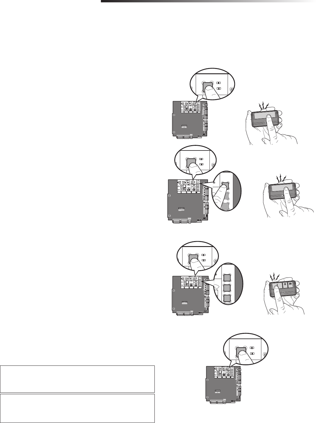
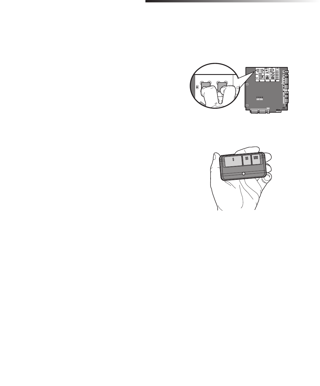
TO ADD OR REPROGRAM A REMOTE CONTROL
(NOT PROVIDED)
Press and release the LEARN button (operator will beep and green XMITTER LED
will light).
Press the remote control button for the desired function. The operator will
automatically exit learn mode (operator will beep and green XMITTER LED will
go out) if programming is successful.
This programming step will program a single button as an open, close, and stop. To
program additional Security✚ 2.0™ remote controls, repeat the steps until all the
remote controls are programmed.
PROGRAM OPEN ONLY ON A 1-BUTTON REMOTE
CONTROL
Press and release the LEARN button (operator will beep and green XMITTER LED
will light).
Press the OPEN button.
Press the remote control button. The operator will automatically exit learn
mode (operator will beep and green XMITTER LED will go out) if programming
is successful.
To program additional Security✚ 2.0™ remote controls, repeat the steps until all the
remote controls are programmed.
PROGRAM OPEN, STOP, AND CLOSE ON A 3-BUTTON
REMOTE CONTROL
Press and release the LEARN button (operator will beep and green XMITTER LED
will light).
Press the OPEN, CLOSE, or STOP button for the desired function.
Press the remote control button for the desired function. The operator will
automatically exit learn mode (operator will beep and green XMITTER LED will
go out) if programming is successful.
To program additional buttons or Security✚ 2.0™ remote controls, repeat the steps
until all the buttons or remote controls are programmed.
1
2
Press and release the LEARN button (operator will beep and green XMITTER LED
will light).
Press and hold the LEARN button again until the green XMITTER LED goes out
(approximately 6 seconds). All remote control codes are now erased.
1
ERASE ALL CODES
1
2
3
2
REMOTE CONTROLS
1
2
3
NOTICE: To comply with FCC and/or Industry Canada (IC) rules, adjustment or modifications of this transceiver are prohibited. THERE ARE
NO USER SERVICEABLE PARTS.
This device complies with Part 15 of the FCC rules and IC RSS-210. Operation is subject to the following two conditions: (1) this device may
not cause harmful interference, and (2) this device must accept any interference received, including interference that may cause undesired
operation.
This Class B digital apparatus complies with Canadian ICES-003.
AVIS : Les règles de la FCC et/ou d’Industrie Canada (IC) interdisent tout ajustement ou toute modification de ce récepteur. IL N’EXISTE
AUCUNE PIÈCE SUSCEPTIBLE D’ÊTRE ENTRETENUE PAR L’UTILISATEUR.
Cet appareil est conforme aux dispositions de la partie 15 du règlement de la FCC et de la norme IC RSS-210. Son utilisation est assujettie
aux deux conditions suivantes : (1) ce dispositif ne peut causer des interférences nuisibles, et (2) ce dispositif doit accepter toute
interférence reçue, y compris une interférence pouvant causer un fonctionnement non souhaité.
Cet appareil numérique de la classe B est conforme à la norme NMB-003 du Canada.
A total of 50 Security✚ 2.0™ remote controls and 2 keyless entries (1 PIN for each keyless entry) can be programmed to the operator. NOTE: When the memory is full the
operator will exit programming mode and the remote control/keyless entry will not be programmed. The memory will need to be erased before programming any additional
remote controls/keyless entries. If installing an 86LM to extend the range of the remote controls DO NOT bend the antenna.
28
!
!
!!
!
!
A
D
EF
B
C
MANUAL RELEASE + RESET BUTTON + REMOTE CONTROL + PARTY MODE
OPERATION
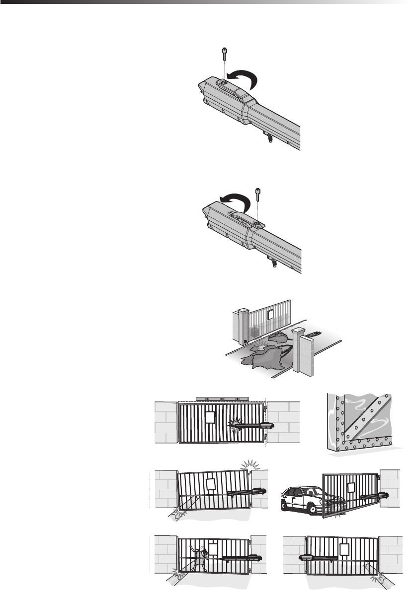
MANUAL RELEASE
In case of a power failure, the operator can be disengaged from the gate. With an
operator, the release action may sometimes feel stiff/jerky, which is normal and has
no effect on function.
RELEASE
Insert the key into the lock.
Turn the key counter-clockwise 180°.
Turn the release lever counter-clockwise 180°.
Operator is in manual mode and the gate can be opened and closed manually.
ENGAGE
Turn the release lever clockwise 180°. This engages the motor.
Turn the key clockwise 180°. This locks the release lever.
Remove the key and store in a safe place.
The operator is now engaged.
1
2
3
1
2
3
RESET BUTTON
The reset button is located on the side of the control box and serves several functions.
Pressing the reset button will stop a moving gate during a normal open/close cycle,
like a stop button. The operator does not need to be reset after doing this.
PROGRAMMING LIMITS RESET
If a mistake is made while programming the limits press the reset button to
start over.
OPERATOR ALARM
If a contact sensor detects an obstruction twice consecutively the alarm will sound
(up to 5 minutes) and the operator will need to be reset.
When the inherent force of the operator (RPM/current sensor) detects the
following (twice consecutively) the alarm will sound (up to 5 minutes) and the
operator will need to be reset:
A. The operator arm or gate is incorrectly installed.
B. The gate does not meet specifications.
C. Gate hinges are too tight or broken and the gate is not moving freely.
D. The gate is moving and a car pushes the gate.
E. A foreign object is on the gate frame while the gate is moving.
F. The gate hits the driveway, curb or other, and gets stuck or bent in an
awkward position.
Remove any obstructions. Press the reset button to shut off the alarm and reset
the operator. After the operator is reset, normal functions will resume.
The operator alarm will beep 3 times with a command if the battery is low.
REMOTE CONTROL
Once the remote control has been programmed the operator will operate as follows:
When gate is in the closed position, activation of the remote control button will open
the gate. During the open cycle another activation of the remote control will stop the
gate and the next activation of the remote control will close the gate.
When the gate is in the open position, activation of the remote control button will
close the gate. If the remote control is activated while the gate is closing, the gate will
stop and the next activation will open the gate.
PARTY MODE
If the Timer-to-Close feature is enabled and you would like the gate to remain open,
open the gate fully, then press the reset button. The next command given by a
LiftMaster remote control or SINGLE BUTTON on the control board will close the gate
and return the operator to normal operation.
NOTE: If an alternative radio receiver is wired to the operator, the receiver must be
wired to the SINGLE BUTTON and CTRL PWR inputs.

29
NOTES:
• Severe or high cycle usage will require more frequent maintenance checks.
• It is suggested that while at the site voltage readings be taken at the operator. Using a digital voltmeter, verify that the incoming voltage to the operator it is within ten
percent of the operator’s rating.
Disconnect all power (AC, solar, battery) to the operator before servicing. The operator's AC Power switch ONLY turns off AC power to the control board and
DOES NOT turn off battery power. ALWAYS disconnect the batteries to service the operator.
MAINTENANCE CHART + BATTERIES
MAINTENANCE
MAINTENANCE CHART
DESCRIPTION TASK CHECK AT LEAST ONCE EVERY
MONTH 6 MONTHS 3 YEARS
Entrapment Protection Devices Check and test for proper operation X
Warning Signs Make sure they are present X
Manual Release Check and test for proper operation X
Gate Inspect for wear or damage X
Accessories Check all for proper operation X
Electrical Inspect all wire connections X
Mounting Hardware Check for tightness X
Operator Inspect for wear or damage X
Batteries Replace X
BATTERIES
Batteries will degrade over time depending on temperature and usage. For best
performance, the batteries should be replaced every 3 years. Use only LiftMaster
part 29-NP712 for replacement batteries. The operator comes with two 7AH
batteries.
Two 33AH (A12330SGLPK) may be used in place of the 7AH batteries for a Large
Metal Control Box solar installation. A Battery tray (Model K10-36183) is required
for the 33AH application.
The batteries contain lead and need to be disposed of properly. Batteries do not
perform well in extremely cold temperatures.
The operator alarm will beep 3 times with a command if the battery is low.
30
SET OPEN SET CLOSE
MOVE
GATE
OFF
5
10
60
180 MIN MAX
(SECONDS)
OFF ON
OPEN CLOSE STOP
INPUT POWER
BATT CHARGING
TIMER
GATE MOVING
BATT LOW
ACC PWR OVLD
DIAGNOSTIC
CODES
STATUS:
SBC
“FIRE
DEPT ”
OPEN
EXIT
SHADOW
CLOSE
EYES/
INTERRUPT
LOCK
N.O.
COM
N.C.
+ -
+ -
ACCESSORY
POWER
ON SW.
EXP.
BOARD
XMITTER
NETWORK
PRESS &
RELEASE
TO BEGIN
SETUP
CLASS 2 SUPPLY
24 VOLTS
1
LIMIT
2
- + + -
J5
+
SOLAR /
CHARGER
J15
+
BATT +
DC
POWER
ID RESET ALARM
GROUND
BR GRN WT YE BLU RED BR GRN WT YE BLU RED
Open
Close
Stop
Com
Com
Com
Com
Com
Fire Dept
Exit
Shadow
Interrupt
Comm Link Data A
Comm Link Data B
Close (+)
Close (-)
Lock N.C. (Maglock)
Com
Lock N.O. (Solenoid)
Com (-)
AccPower +24 Vdc
Com (-)
AccPower +24 Vdc
3 Button
Station
Fire Dept.
Exit Loop
Shadow Loop
Interrupt Loop
Comm Link
Open Direction
Safety
Close Direction
Safety
Mag and
Solenoid Lock
A
B
C
D
E
F
G
H
I
J
K
L
M
N
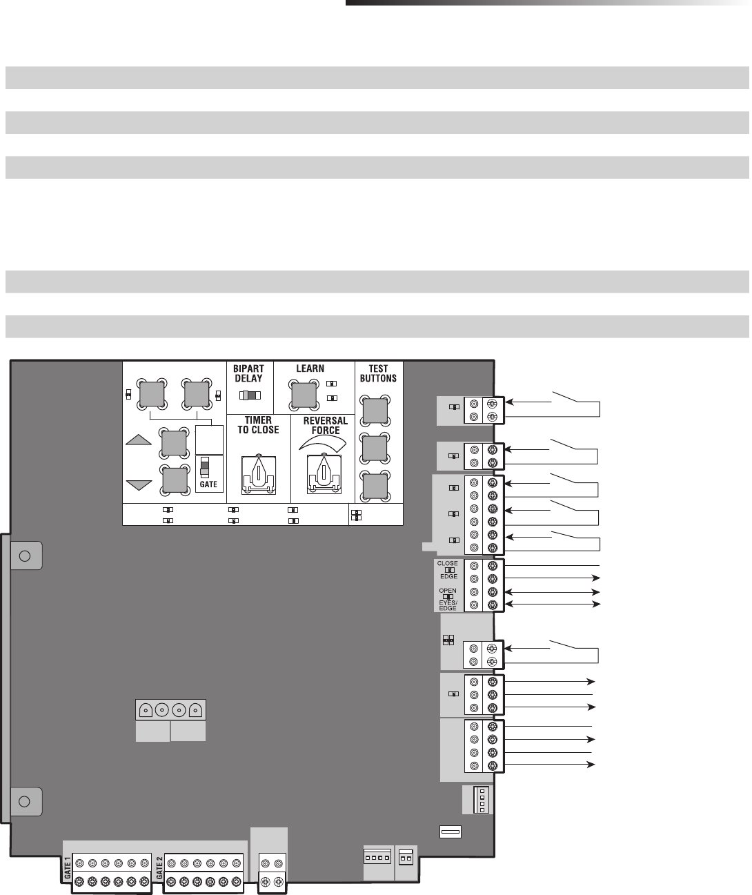
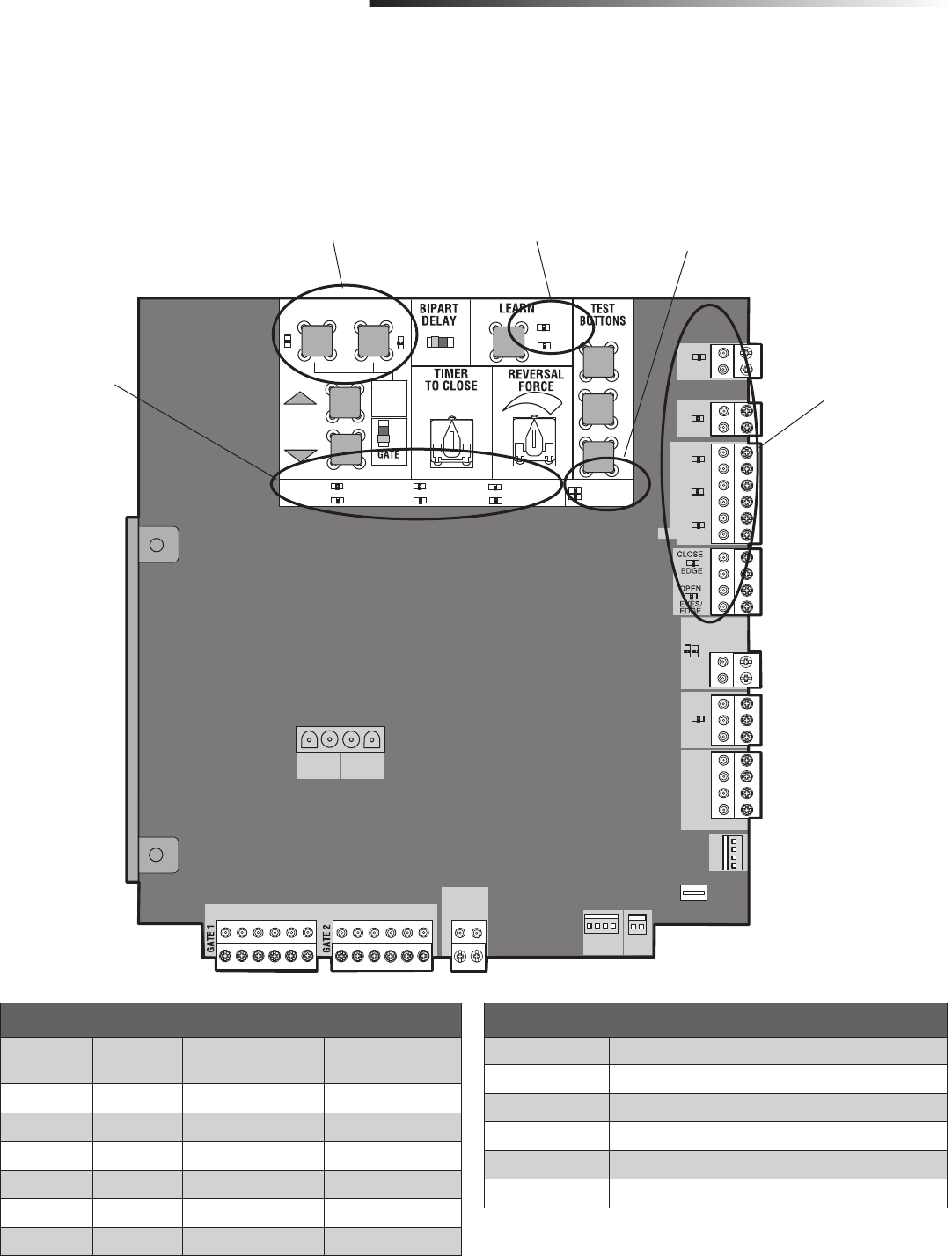
CONTROL BOARD OVERVIEW
ADDITIONAL FEATURES
CONTROL BOARD OVERVIEW
SET OPEN Button The SET OPEN button sets the OPEN limit. See Adjust Limits section.
SET CLOSE Button The SET CLOSE button sets the CLOSE limit. See Adjust Limits section.
MOVE GATE Button The MOVE GATE buttons will either open or close the gate when the operator is in Limit setting mode. See Adjust Limits section.
BIPART DELAY Switch The Bipart delay switch is used only for dual gates. See Bipart Delay section.
LEARN Button The LEARN button is for programming remote controls and the network.
TIMER-TO-CLOSE dial The TIMER-TO-CLOSE (TTC) dial can be set to automatically close the gate after a specified time period. The TTC is factory set to OFF. If the
TTC is set to the OFF position, then the gate will remain open until the operator receives another command from a control. Rotate the
TIMER-TO-CLOSE dial to the desired setting. The range is 0 to 180 seconds, 0 seconds is OFF.
NOTE: Any radio command, single button control, or CLOSE command on the control board prior to the TTC expiring will close the gate.
The TTC is reset by any signals from the open controls, loops, close edges, and close photoelectric sensors (IR’s).
REVERSAL FORCE dial The REVERSAL FORCE dial adjusts the force. See Force Adjustment section.
TEST BUTTONS The TEST BUTTONS will operate the gate (OPEN, STOP and CLOSE).
STATUS LEDs The STATUS LEDs are diagnostic codes for the operator. See Status LED Chart in the Troubleshooting section.
Switched ON with gate motion. Always ON with
expansion board connected. Switches Off to save
battery power if expansion board disconnected.
Always ON
Acc. Power
Open (+)
Open (-)

31
ACCESSORY FEATURES ON CONTROL BOARD
ADDITIONAL FEATURES
ACCESSORY FEATURES ON CONTROL BOARD
AOpen Input (& common)
(3-Button Control Station, 4 terminals
total)
Open command - opens a closed gate.
Hard open (maintained switch overrides external safeties and resets alarm condition)
If maintained, pauses Timer-to-Close at OPEN limit.
Opens a closing gate and holds open an open gate (within line-of-sight).
BClose Input (& common)
(3-Button Control Station, 4 terminals
total)
Close command - closes an open gate.
Hard close (maintained switch overrides external safeties and resets alarm condition within line-of-sight)
CStop Input (& common)
(3-Button Control Station, 4 terminals
total)
Stop command - stops a moving gate.
Hard stop (maintained switch overrides Open and Close commands and resets alarm condition)
If maintained, pauses Timer-to-Close at OPEN limit.
Overrides Open and Close commands (within line-of-sight).
DFire Dept Open Input
(2 terminals)
Acts as hard open.
Maintained input overrides (ignores) external safeties (photoelectric sensor and edge), pauses Timer-to-Close
momentary input logic as single button control and safeties remain active, re-enables Timer-to-Close.
EExit Loop Input
(2 terminals)
Open command - opens a closed gate.
Soft open (maintained switch does not override external safeties and does not reset alarm condition)
If maintained, pauses Timer-to-Close at OPEN limit.
Opens a closing gate and holds open an open gate.
FShadow Loop Input
(2 terminals)
Loop detector connection when loop is positioned under gate.
- Holds open gate at open limit
- Disregarded at CLOSE limit and during gate motion
- Pauses Timer-to-Close at OPEN limit
GCLOSE EYES/Interrupt Loop Input
(2 terminals)
CLOSE EYES/Interrupt Loop detector connection when loop is along the side of the gate.
- Holds open gate at open limit
- Stops and reverses a closing gate to open limit
- Pauses Timer-to-Close at OPEN limit
Close Direction Photoelectric Sensors, IR, or Infra-red detector wired to CLOSE EYES Input, disregarded during gate
opening.
Pulsed Photoelectric Sensors = monitored device putting out a pulse train when unblocked.
Photoelectric Sensors, IR, Infra-red detector, contact opens fully with obstruction.
HClose Edge
(2 terminals)
Close Direction Edge Sensor to Close Safety Input, disregarded during gate opening
IOpen Eyes/Edge
(2 terminals)
Open Direction Photoelectric Sensors, IR, Infra-red detector wired or Edge Sensor to Close Entrapments Input,
disregarded during gate closing,
Pulsed Photoelectric Sensors = monitored device putting out a pulse train when unblocked.
Photoelectric Sensors, IR, Infra-red detector, edge sensor = normally open contact, contact reverses for 2 seconds
with obstruction.
JComm Link
(2 terminals)
Commercial Link (two wires) - connects two operators together (primary-secondary wired connection)
KLock Outputs: Maglock
(2 terminals, N.C. and COM)
Relay contact output, Normally - closed (N.C.) output for maglocks
Relay activates prior to motor activation and during motor run. Relay is off when motor is off.
LSolenoid Lock & Common
(2 terminals, N.O. and COM)
Normally - open (N.O.) output for solenoid locks
Relay activates prior to motor activation and during motor run. Relay is off when motor is off.
MAccessory Power Out
Switched, (2 terminals)
24 Vdc voltage out to power accessories, will turn off when gate is not in motion to save battery power
Always on if Expansion Board is connected.
NAccessory Power Out
Un-switched, (2 terminals)
24 Vdc voltage out to power accessories, always ON
32
EXPANSION BOARD OVERVIEW
ADDITIONAL FEATURES
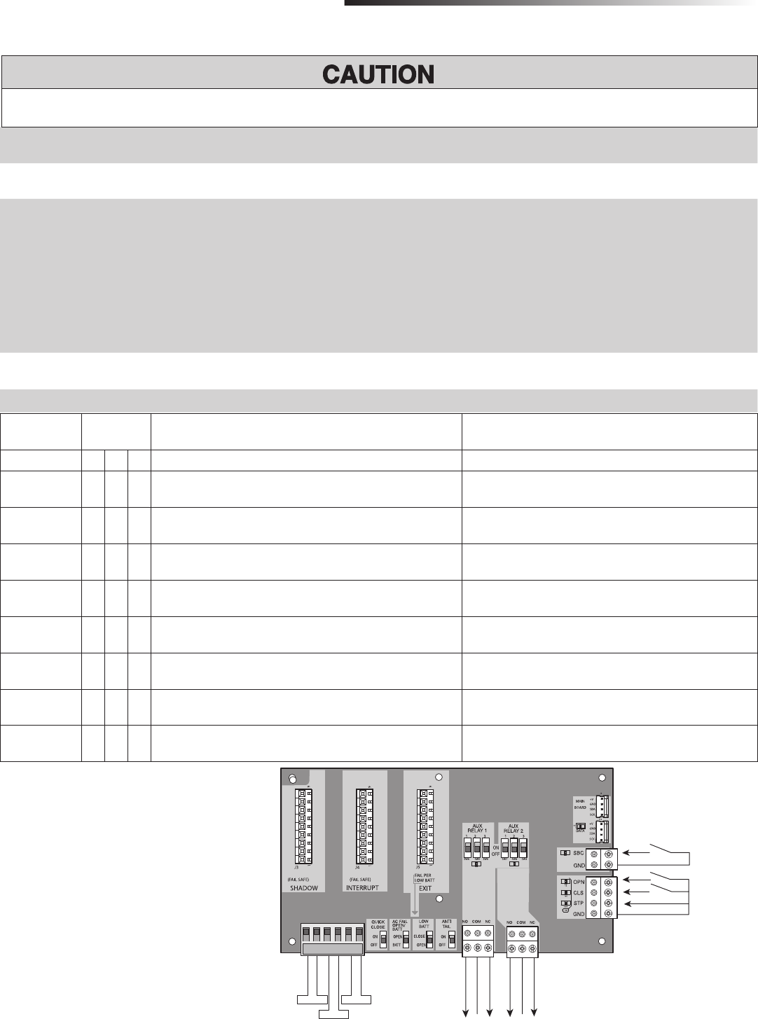
EXPANSION BOARD OVERVIEW
QUICK CLOSE Switch OFF: No change to the gate's normal operation.
ON: When CLOSE EYES/Interrupt loop is deactivated it causes an opening or a stopped gate to close (ignores the Timer-to-Close).
AC FAIL OPEN/BATT Switch OPEN: Loss of AC power will cause gate to immediately OPEN and remain OPEN until AC power is restored (enabling the Timer-to-Close).
BATT: With loss of AC power, gate will remain in present position and operator is powered from batteries.
LOW BATT/EXIT LOOP FAIL
Switch
• When AC power is OFF and battery voltage is low the gate will latch at a limit until AC power is restored or batteries voltage increases.
• Option select switch set to OPEN forces gate to latch at the OPEN limit if it is at the OPEN limit or on next open command until AC power is
restored or battery voltage increases.
• Option select switch set to CLOSE forces gate to latch at CLOSE limit if at CLOSE limit or on next CLOSE command until AC power restored or
battery voltage increases.
• Constant pressure on a hard command input overrides to open or close the gate.
• Low battery detect point = 22 V
• When set to OPEN, if the EXIT plug-in loop detector detects a fault, then the gate will open and remain open until fault is cleared. When set to
CLOSE, then plug-in EXIT loop detector faults are ignored (EXIT loop is faulted and inoperative).
ANTI-TAIL OPEN/CLOSE
SELECTION switch
OFF: When CLOSE EYES/Interrupt loop is activated it causes a closing gate to stop and reverse.
ON: When CLOSE EYES/Interrupt loop is activated it causes a closing gate to pause. Once the vehicle is clear the gate will continue to close.
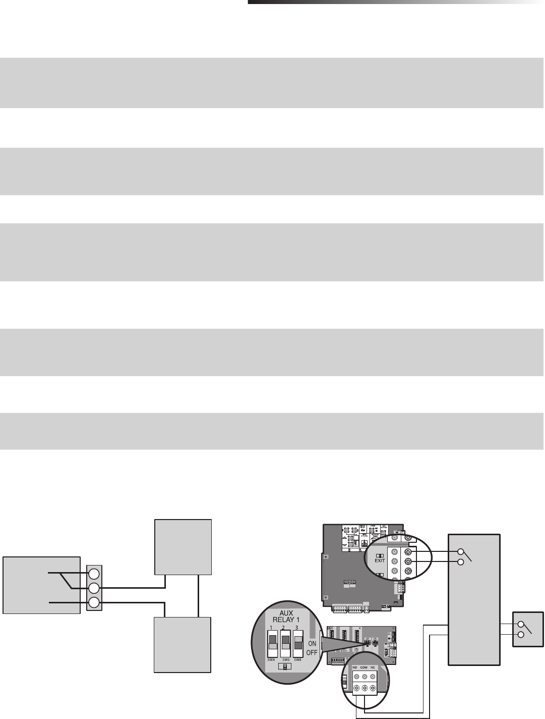
AUX RELAY switches Set the AUX RELAY switches as needed to obtain the desired function:
To AVOID damaging the circuit board, relays or accessories, DO NOT connect more than 42 Vdc (32 Vac) to the AUX relay contact terminal blocks.
Com
Single
Button
Control
Station
A
SBC
3-Button
Control
Station
B
C
Com
Open
Close
Stop
AUX Relay 2 N.C.
Com
AUX Relay 2 N.O.
AUX Relay 1 N.C.
Com
AUX Relay 1 N.O.
Exit Loop
Interrupt Loop
Shadow Loop
D
E
F
G
HI
CYCLE COUNT
* First, note the current Aux Relay switch positions. To
determine the actual cycles that the gate operator has
run (in thousands), set all three Aux Relay switches to
the ON setting for Aux Relay 1. The Expansion Board’s
OPEN, CLOSE, and STOP LEDs will blink out the cycle
count, with OPEN LED blinking 1000’s, CLOSE LED blink
10,000’s, STOP LED blinking 100,000’s, and
simultaneously all three LED’s blink 1,000,000’s (e.g.
Open blinks 3 times, Close blinks 6 times, and Stop
blinks once. Cycle count is 163,000.). Cycle count
displayed is between 1,000 and 9,999,000 cycles.
After servicing, set Aux Relay switches back to their
appropriate positions. Cycle count cannot be reset or
changed. If under 1,000 cycles the Open, Close, and
Stop LEDs will turn on for 10 seconds, then turn off.
AUX RELAY
SETTING
SWITCH
SETTINGS
AUX RELAY 1 AUX RELAY 2
123
Off (no feature
selected)
OFF OFF OFF Relay always off. Use this Aux Relay setting to conserve
battery power. Relay always off. Use this Aux Relay setting to conserve battery power.
Open Limit
Switch
OFF OFF ON Energizes at open limit. Use with SAMS (Sequenced Access Management
System, jointly with barrier gate) Energizes when at open limit. Use with SAMS (Sequenced Access
Management System, jointly with barrier gate)
Close Limit
Switch
OFF ON OFF Energizes when not at close limit. Connect “Gate Close/Secure” indicator
(e.g. light). Energizes when not at close limit. Connect “Gate Not Closed/Secure”
indicator (e.g. light).
Gate Motion OFF ON ON Energizes when motor is on (gate in motion). Connect “Gate In Motion”
indicator (e.g. warning light or sounder). Energizes when motor is on (gate in motion). Connect “Gate In Motion”
indicator (e.g. warning light or sounder).
Pre-Motion
Delay
ON OFF OFF Energizes 3 seconds before gate motion and remains energized during gate
motion. Connect “Gate In Motion” indicator (e.g. warning light or sounder). Not used.
Power ON ON OFF Energizes when AC power or solar power is present. There is approximately
a 10-12 second delay before relay cutoff, after AC shutdown. Energizes when on battery power. There is approximately a 10-12
second delay before relay cutoff, after AC shutdown.
Tamper ON OFF ON Energizes if gate is manually tampered with by being pushed off of close
limit. Connect alert (e.g. light or sounder). Energizes if gate is manually tampered with by being pushed off of close
limit. Connect alert (e.g. light or sounder).
Cycle Quantity
Feedback*
ON ON ON The OPEN, CLOSE, and STOP LEDs will blink out the cycle count
See below. Not used.
33
ACCESSORY FEATURES ON EXPANSION BOARD
ADDITIONAL FEATURES
ACCESSORY FEATURES ON EXPANSION BOARD
AOpen Input (& common)
(3-Button Control Station,
4 terminals total)
Open command - opens a closed gate.
Soft close (maintained switch does not override external safeties and does not reset alarm condition)
If maintained, pauses Timer-to-Close at OPEN limit.
Opens a closing gate and holds open an open gate.
BClose Input (& common)
(3-Button Control Station,
4 terminals total)
Close command - closes an open gate.
Soft close (maintained switch does not override external safeties and does not reset alarm condition)
CStop Input (& common)
(3-PB station, 4 terminals total)
Stop command - stops a moving gate.
Hard stop (maintained switch overrides Open and Close commands and resets alarm condition)
If maintained, pauses Timer-to-Close at OPEN limit.
Overrides an Open or Close command.
DSingle Button Control, SBC
(2 terminals)
Gate command sequence - Open, Stop, Close, Stop, ...
Soft open (maintained switch does not override external safeties and does not reset alarm condition)
EExit Loop Input
(2 terminals)
Loop wire connection for plug-in loop detector when loop is inside secured area near gate.
Open command - opens a closed gate.
Soft open (maintained switch does not override external safeties and does not reset alarm condition)
If maintained, pauses Timer-to-Close at OPEN limit.
Opens a closing gate and holds open an open gate.
FShadow Loop Input
(2 terminals)
Loop wire connection for plug-in loop detector when loop is along side gate.
- Holds open gate at open
- Disregarded at Close limit and during gate motion
- Pauses Timer-to-Close at Open Limit
GInterrupt Loop Input
(2 terminals)
Loop wire connection for plug-in loop detector when loop is positioned under gate.
- Holds open gate at open
- Stops and reverses a closing gate
- Pauses Timer-to-Close at Open Limit
HAUX Relay #1 Normally - open and normally - closed relay contacts to control external devices,
Function of relay contact activation determined by AUX Relay #1 option switch settings. (For connection of Class
2, low voltage (<32 V), DC or AC, max 5 Amps, power sources only)
IAUX Relay #2 Normally-open and normally-closed relay contacts to control external devices,
Function of relay contact activation determined by AUX Relay #2 option switch settings. (For connection of Class
2, low voltage (<32 V), DC or AC, max 5 Amps, power sources only)
SET OPEN SET CLO E
MOVE
G TE 5
0
6
S CO D )
FF ON
N UT P WER
A T CH RG NG
T MER
GA E M
TATUS
CC SS RY
P WER
N SW
XP
B ARD
XM T R
N W RK
E A E
E UP
IMT
2
SO AR /
CH RG R
J 5
+
A T +
DC
P WER
ID R S T A A M
RO ND
BR G N WT YE B U ED BR G N WT E LU ED
Aux Relay
N.C.
COM
N.O.
Class 2 Power Source
(32 V max, 5 A max)
+—
Warning Light
AUX RELAY WIRING EXAMPLE
Access Device
Exit Input
Shadow Input
AUX Relay 1
C
NO
Auxiliary
Command
SAMS WIRING WITH RELAYS NOT ENERGIZED
Dipswitch settings for AUX Relay 1:
1-OFF, 2-OFF, 3-ON
Main Board
Expansion Board
Barrier Arm Operator

34
GATE OPERATOR SETUP EXAMPLES
ADDITIONAL FEATURES
GATE OPERATOR SETUP EXAMPLES
The following are example setups for the gate operator. Your specific site requirements may be different. Always setup the operator system to the site requirements, including
all necessary secondary entrapment protection systems.
RESIDENTIAL SMALL: One to four residential homes sharing a gated entrance/exit, allowing vehicle access trumps security concerns
RESIDENTIAL LARGE: A residential community (more than four homes) having one or more gated entrances/exits, allowing vehicle access trumps security concerns
COMMERCIAL: Business site where security (gate closed) is important
INDUSTRIAL: Large business site where security is required
Setting RESIDENTIAL SMALL RESIDENTIAL LARGE COMMERCIAL INDUSTRIAL
Quick Close switch setting Normally set to OFF. Normal gate
close (timer or control). Normally set to OFF. Normal gate
close (timer or control). Normally set to OFF. Normal gate
close (timer or control). Set to ON, so that gate closes
immediately after vehicle passes
interrupt loop.
AC Fail Open switch setting Normally set to BATT. Run on
battery if AC power fails. Normally set to BATT. For local
jurisdiction requirement, set to
OPEN so that gate immediately
opens upon AC power fail.
Normally set to BATT. Run on
battery if AC power fails. Normally set to BATT. Run on
battery if AC power fails.
Low Battery switch setting Normally set to OPEN. If powered
from battery and battery is low,
gate stays open.
Normally set to OPEN. If powered
from battery and battery is low,
gate stays open.
Normally set to CLOSE. If powered
from battery and battery is low,
gate stays close.
Normally set to CLOSE. If powered
from battery and battery is low,
gate stays close.
Anti-Tail switch setting Normally set to OFF. Interrupt loop
reverses a closing gate. Normally set to OFF. Interrupt loop
reverses a closing gate. Set to ON. In attempt to prevent
vehicle tail-gating, interrupt loop
pauses a closing gate.
Set to ON. In attempt to prevent
vehicle tail-gating, interrupt loop
pauses a closing gate.
Bipart Delay switch setting For DUAL-GATE site, set to ON for
gate that delays upon opening For DUAL-GATE site, set to ON for
gate that delays upon opening For DUAL-GATE site, set to ON for
gate that delays upon opening For DUAL-GATE site, set to ON for
gate that delays upon opening
Aux Relay Out – Open
Limit Switch
Typically not required. Use with SAMS (Sequence Access
Management System) 1) Use with SAMS (Sequence Access
Management System)
2) Connect “Gate Open” indicator
(e.g. light)
1) Use with SAMS (Sequence Access
Management System)
2) Connect “Gate Open” indicator
(e.g. light)
Aux Relay Out – Close
Limit Switch
Typically not required. Typically not required. Connect “Gate Close/Secure”
indicator (e.g. light) Connect “Gate Close/Secure”
indicator (e.g. light)
Aux Relay Out – Gate
Motion
Attach alert signal (audible or
visual alert system) Attach alert signal (audible or
visual alert system) Attach alert signal (audible or
visual alert system) Attach alert signal (audible or
visual alert system)
Aux Relay Out – Pre-
Motion Delay
Attach alert signal (audible or
visual alert system) Attach alert signal (audible or
visual alert system) Attach alert signal (audible or
visual alert system) Attach alert signal (audible or
visual alert system)
Aux Relay Out – Power Attach visual alert to know when
system is charging batteries (i.e.
not running on batteries)
Attach visual alert to know when
system is charging batteries (i.e.
not running on batteries)
Attach visual alert to know when
system is charging batteries (i.e.
not running on batteries)
Attach visual alert to know when
system is charging batteries (i.e.
not running on batteries)
Aux Relay Out – Tamper Attach alert signal (audible or
visual alert system) to indicate if
gate is manually tampered with by
being pushed off of close limit
Attach alert signal (audible or
visual alert system) to indicate if
gate is manually tampered with by
being pushed off of close limit
Attach alert signal (audible or
visual alert system) to indicate if
gate is manually tampered with by
being pushed off of close limit
Attach alert signal (audible or
visual alert system) to indicate if
gate is manually tampered with by
being pushed off of close limit
Cycle Quantity Feedback Use during servicing only to
determine operator cycles Use during servicing only to
determine operator cycles Use during servicing only to
determine operator cycles Use during servicing only to
determine operator cycles
Fire Dept Open input Typically not required. Connect emergency access system
(Knox box switch, SOS system, etc.) Typically not required. Typically not required.
35
Ensure the gate is closed.
Press the SET OPEN and SET CLOSE buttons simultaneously to enter limit setting
mode.
Press and hold the OPEN or CLOSE button on the remote control until the gate
reaches the desired open position. The gate can be jogged back and forth using
the OPEN and CLOSE buttons on the remote control.
Once the gate is in the desired open position, press and release the STOP button
on the remote control.
Press and release the OPEN button on the remote control again to set the open
limit.
Press and hold the CLOSE or OPEN button on the remote control until the gate
reaches the desired close position. The gate can be jogged back and forth using
the OPEN and CLOSE buttons on the remote control.
Once the gate is in the desired close position, press and release the STOP button
on the remote control.
Press and release the CLOSE button on the remote control again to set the close
limit.
Cycle the gate open and close. This automatically sets the force.
When limits are set properly the operator will automatically exit limit setting mode.
LIMIT SETUP WITH A REMOTE CONTROL
LIMIT SETUP WITH A REMOTE CONTROL
ADDITIONAL FEATURES
4
1
2
5
3
6
To set the limits using a remote control, first you will need a 3-button remote control that has been programmed for OPEN, CLOSE, and STOP. Refer to the Programming
section.
For dual gate applications the limits will have to be set for each
operator. The gate MUST be attached to the operator before setting the
limits and force.
INITIAL LIMITS AND FORCE ADJUSTMENT
ADJUST THE LIMITS
7
8
Set the Close Limit Only
Press the SET OPEN and SET CLOSE buttons simultaneously to enter limit setting
mode.
Press and hold the CLOSE button on the remote control until the gate reaches the
desired close position. The gate can be jogged back and forth using the OPEN
and CLOSE buttons on the remote control.
Once the gate is in the desired close position, press and release the STOP button
on the remote control.
Press and release the CLOSE button on the remote control again to set the close
limit.
When the close limit is set properly the operator will automatically exit limit setting
mode.
4
1
2
3
Set the Open Limit Only
Press the SET OPEN and SET CLOSE buttons simultaneously to enter limit setting
mode.
Press and hold the OPEN button on the remote control until the gate reaches the
desired open position. The gate can be jogged back and forth using the OPEN
and CLOSE buttons on the remote control.
Once the gate is in the desired open position, press and release the STOP button
on the remote control.
Press and release the OPEN button on the remote control again to set the open
limit.
When the open limit is set properly the operator will automatically exit limit setting
mode.
4
1
2
3
If the limits have already been set the operator will exit the limit setting mode after resetting each limit.
3-Button Remote Control programmed for OPEN, CLOSE, and STOP
ET OP N SET C OSE
MO E
G TE
F
5
10
6
0M
O F O
N UT OW R
A T CH R I G
M R
TE M V NG
AT LOW
CC P R OV
A NO T
CO ES
TA US
“ RE
DE T
E I
H
C O E
Y S
N ER
CC S ORY
OWER
N W
XP
R
E W R
TU
1
MT
2
5
OL R /
HA GER
15
BA T
P WER
BR G N WT E B U ED R G N WT YE B U R D
SET OPEN SET CLOSE
F
B
D
36
The control board is equipped with many LEDs that have a variety of functions. The control board LEDs indicate the status of the operator, assist with programming, and
diagnose potential problems with the operator.
CONTROL BOARD LEDS
TROUBLESHOOTING
SET OPEN SET CLOSE
MOVE
GATE
OFF
5
10
60
180 MIN MAX
(SECONDS)
OFF ON
OPEN CLOSE STOP
INPUT POWER
BATT CHARGING
TIMER
GATE MOVING
BATT LOW
ACC PWR OVLD DIAGNOSTIC
CODES
STATUS:
SBC
“FIRE
DEPT.”
OPEN
EXIT
SHADOW
CLOSE
EYES/
INTERRUPT
LOCK
N.O.
COM
N.C.
+ -
+ -
ACCESSORY
POWER
ON SW.
EXP.
BOARD
XMITTER
NETWORK
PRESS &
RELEASE
TO BEGIN
SETUP
CLASS 2 SUPPLY
24 VOLTS
1
LIMIT
2
- + + -
J5
+ -
SOLAR /
CHARGER
J15
+ -
BATT - +
DC
POWER
ID RESET ALARM
GROUND
BR GRN WT YE BLU RED BR GRN WT YE BLU RED
STATUS LEDS
CONTROL BOARD LEDS
GREEN XMITTER LED
XMITTER LED EXPLANATION
OFF No remote control activity, normal operation.
ON Programming mode active.
FAST Recognized remote control signal.
FASTER Unrecognized remote control signal.
FASTEST Remote controls are being erased.
LIMIT SETUP LEDS
SET OPEN
LED
SET CLOSE
LED
OPERATOR MODE EXPLANATION
BLINKING BLINKING NORMAL MODE Limits are not set.
OFF OFF NORMAL MODE Limits are set.
BLINKING BLINKING LIMIT SETTING MODE Limits are not set.
BLINKING ON LIMIT SETTING MODE Open limit is not set.
ON BLINKING LIMIT SETTING MODE Close limit is not set.
ON ON LIMIT SETTING MODE Limits are set.
LIMIT SETUP LEDS GREEN XMITTER LED DIAGNOSTIC CODES LEDS
INPUT LEDS

37
INPUT LEDS
OPEN INPUT OFF Input inactive
ON Input active
BLINK Input active on other operator
CLOSE INPUT OFF Input inactive
ON Input active
BLINK Input active on other operator
STOP INPUT OFF Input inactive
ON Input active
BLINK Input active on other operator
FIRE DEPT
INPUT
OFF Input inactive
ON Input active
BLINK Input active on other operator
SBC INPUT OFF Input inactive
ON Input active
BLINK Input active on other operator
OPEN SAFETY
INPUT
OFF Input inactive
ON Input active
BLINK Input active on other operator
CLOSE SAFETY
INPUT
OFF Input inactive
ON Input active
BLINK Input active on other operator
STATUS LEDS
INPUT POWER OFF OFF state
ON AC charger or Solar power available
BATT
CHARGING
OFF Not charging
ON Trickle charge
FAST BLINK High current charge
FASTER BLINK Over voltage error
TIMER OFF The timer is disabled
ON The timer is enabled
MEDIUM BLINK The timer is running
FAST BLINK The timer is paused
FASTER BLINK The timer is cancelled
GATE MOVING OFF The gate is stopped
ON The gate is opening or closing
FASTEST BLINK The operator is in E2
BATT LOW OFF No battery error
ON Battery low error
SLOW BLINK Battery dead error
MEDIUM BLINK Battery over current error
FAST BLINK Battery over voltage error
FASTER BLINK Extreme temperature error
FASTEST BLINK Battery disconnected error
ACC PWR OVLD OFF OFF state
ON Accessory overload protector opened
CONTROL BOARD LEDS
TROUBLESHOOTING
CONTROL BOARD LEDS
YELLOW DIAGNOSTIC LED
# BLINKS MEANING CORRECTION
1 BLINK Low Power Mode (not an error)
2 BLINKS ID resistor failure Check ID resistor wiring, clear limit
settings and reset limits
3 BLINKS Exceeded Maximum
Run Timer
Check gate travel, if necessary adjust
force setting
5 BLINKS RPM (obstruction) Check for obstruction, if necessary
adjust force setting
6 BLINKS Current (obstruction) Check for obstruction, if necessary
adjust force setting
7 BLINKS Position failure Check gate travel, clear limit settings
and reset limits
12 BLINKS Loop Error One of the loops is in error. Refer to the
loop detector to determine the error.
RED DIAGNOSTIC LED
# BLINKS MEANING CORRECTION
2 BLINKS Current Sense Motor control circuit fault, replace
control board
3 BLINKS FET Failure Motor control circuit fault, replace
control board
4 BLINKS RAM Failure Memory failure, replace control board
5 BLINKS Flash Memory
Failure
Memory failure, replace control board
6 BLINKS EEPROM Failure Memory failure, replace control board
7 BLINKS Watchdog Failure Controller failure, replace control
board
8 BLINKS Brownout Check power harness or line voltage
9 BLINKS Fail Control Board failure
10-14 BLINKS Software Failure Cycle power to the control board. If
continues replace control board.
DIAGNOSTIC CODES LEDS

38
TROUBLESHOOTING CHART
TROUBLESHOOTING
FAULT POSSIBLE CAUSES CORRECTIONS
Operator does not
run and diagnostic
LED not on.
a) No power to control board
b) Open fuse
c) If on battery power only, low or dead batteries
d) Defective control board
a) Check AC and battery power
b) Check fuses
c) Charge batteries by AC or solar power or replace batteries
d) Replace defective control board
Control board
powers up, but
motor does not run.
a) Check DIAGNOSTIC LEDs
b) Reset button is stuck
c) Stop button active
d) If on battery power only, low or dead batteries
e) Open or Close input active
f) Entrapment Protection Device active
g) Vehicle loop detector or probe active
h) Defective control board
a) Use Diagnostic code to identify issue
b) Check Reset button
c) Check Stop button is not “stuck on”
d) Charges batteries by AC or solar power or replace batteries
e) Check all Open and Close inputs for a “stuck on” input
f) Check all Entrapment Protection Device inputs for a “stuck on” sensor
g) Check all vehicle detector inputs for a “stuck on” detector
h) Replace defective control board
Relay clicks with
command, but motor
does not turn on.
a) Arm jammed or not connected
b) Defective motor or motor wires
c) Defective control board
a) Disengage the arm and ensure arm moves freely
b) Inspect motor wires for open wire, shorted wires, damage, etc. Else, replace arm.
c) Replace defective control board.
Arm moves, but
cannot set correct
limits.
a) Arm does not extend or retract enough during
travel
b) Arm is interfering with mounting bracket
c) Gate is too difficult to move
a) Disengage the arm and ensure arm moves freely
b) Examine the hinge point where the arm mounts to the gate post. Make sure that the arm
housing does not hit or interfere with the gate post or mounting bracket. Correct as
necessary.
c) Disconnect arm from gate and move gate manually. Gate must move easily and freely
through its entire range, limit-to-limit. Repair gate as needed.
Gate does not fully
open or fully close
when setting limits.
a) Arm does not extend or retract enough during
travel
b) Arm is interfering with mounting bracket
c) Gate is too difficult to move
a) Disengage the arm and ensure arm moves freely
b) Examine the hinge point where the arm mounts to the gate post. Make sure that the arm
housing does not hit or interfere with the gate post or mounting bracket. Correct as
necessary.
c) Remove arm from gate and move gate manually. Gate must move easily and freely
through its entire range, limit-to-limit. Repair gate as needed.
Operator does not
respond to a wired
control/command
(example: Open,
Close, SBC, etc.)
a) Check DIAGNOSTIC LEDs
b) Check Open and Close command input LEDs
c) Stop button is active
d) Reset button is stuck
e) If on battery power only, low or dead batteries
f) Entrapment Protection Device active
g) Vehicle loop detector or vehicle probe active
h) Defective control board
a) Use Diagnostic code to identify issue
b) Check all Open and Close inputs for a “stuck on” input
c) Check Stop button is not “stuck on”
d) Check Reset button
e) Charges batteries by AC or solar power or replace batteries
f) Check all Entrapment Protection Device inputs for a “stuck on” sensor
g) Check all vehicle detector inputs for a “stuck on” detector
h) Replace defective control board
Operator does not
respond to a
wireless control or
transmitter
a) Check DIAGNOSTIC LEDs
b) Check XMITTER LED when wireless control is
active
c) Stop button is active
d) Reset button is stuck
e) Poor radio reception
f) Defective control board
a) Use Diagnostic code to identify issue
b) Activate wireless control and check XMITTER LED is on. Re-learn wireless control/
transmitter to control board. Replace wireless control as needed.
c) Check Stop button is not “stuck on”
d) Check Reset button
e) Check if similar wired control operates correctly. Check if wireless controls works properly
when within a few feet of operator. Check operator’s antenna and antenna wire. Check
other wireless controls or devices.
f) Replace defective control board

39
TROUBLESHOOTING CHART
TROUBLESHOOTING
FAULT POSSIBLE CAUSES CORRECTIONS
Gate stops during
travel and reverses
immediately.
a) Check DIAGNOSTIC LEDs
b) Inherent force obstruction detection
c) E xternal Entrapment Protection Device
activation
d) Control (Open, Close) becoming active
e) Vehicle loop detector active
f) Low battery voltage
a) Use Diagnostic code to identify issue
b) Check for obstruction in gate’s path or travel. Remove arm from gate and move gate
manually. Gate must move easily and freely through its entire range, limit-to-limit.
Remove obstruction or repair gate as needed.
c) Check all Entrapment Protection Device inputs for an active sensor
d) Check all Open and Close inputs for an active input
e) Check all vehicle detector inputs for an active detector
f) Battery voltage must be 22.0 Vdc or higher. Charge batteries by AC or solar power or
replace batteries
Gate opens, but will
not close.
a) Check DIAGNOSTIC LEDs
b) Open control active
c) Close Entrapment Protection Device active
d) Vehicle loop detector active
e) Loss of AC power with AC FAIL set to OPEN
f) Low battery with LOW BATT set to OPEN
g) Fire Dept input active
a) Use Diagnostic code to identify issue
b) Check all Open inputs for an active input
c) Check all Entrapment Protection Device inputs for an active sensor
d) Check all vehicle detector inputs for an active detector
e) Check AC power and AC Fail option setting
f) Battery voltage must be 22.0 Vdc or higher. Charge batteries by AC or solar power or
replace batteries
g) Check Fire Dept input
Gate closes, but will
not open.
a) Check DIAGNOSTIC LEDs
b) Open Entrapment Protection Device active
c) Vehicle loop detector active
d) Low battery with LOW BATT switch set to close
e) Low battery with LOW BATT option set to
CLOSE
a) Use Diagnostic code to identify issue
b) Check all Entrapment Protection Device inputs for an active sensor
c) Check all vehicle detector inputs for an active detector
d) Battery voltage must be 22.0 Vdc or higher
e) Check if AC power is available. If no AC power, then running on batteries and battery
voltage must be 22.0 Vdc or higher. Charge batteries by AC or solar power or replace
batteries
Gate does not close
from Timer-to-Close.
a) Timer-to-Close not set
b) Open control active
c) Close Entrapment Protection Device active
d) Vehicle loop detector active
e) Loss of AC power with AC FAIL set to OPEN
f) Low battery with LOW BATT option set to OPEN
g) Fire Dept input active
a) Check Timer-to-Close (TTC) setting
b) Check all Open inputs for an active input
c) Check all Entrapment Protection Device inputs for an active sensor
d) Check all vehicle detector inputs for an active detector
e) Check AC power and AC Fail option setting
f) Check if AC power is available. If no AC power, then running on batteries and battery
voltage must be 22.0 Vdc or higher. Charge batteries by AC or solar power or replace
batteries.
g) Check Fire Dept input
Vehicle Exit loop
activation does not
cause gate to open.
a) Check DIAGNOSTIC LEDs
b) Exit vehicle detector setup incorrectly
c) Defective Exit loop detector or loop wire
d) Low battery with LOW BATT option set to
CLOSE
a) Use Diagnostic code to identify issue
b) Review Exit loop detector settings. Adjust settings as needed.
c) Check Exit loop wire. Replace defective Exit loop detector.
d) Check if AC power is available. If no AC power, then running on batteries and battery
voltage must be 22.0 Vdc or higher. Charge batteries by AC or solar power or replace
batteries.
Vehicle Interrupt
loop does not cause
gate to stop and
reverse.
a) Check DIAGNOSTIC LEDs
b) Vehicle detector setup incorrectly
c) Defective vehicle loop detector or loop wire
a) Use Diagnostic code to identify issue
b) Review Interrupt loop detector settings. Adjust settings as needed
c) Check Interrupt loop wire. Replace defective Interrupt loop detector
Vehicle Shadow loop
does not keep gate
at open limit.
a) Check DIAGNOSTIC LEDs
b) Vehicle detector setup incorrectly
c) Defective vehicle loop detector or loop wire
a) Use Diagnostic code to identify issue
b) Review Shadow loop detector settings. Adjust settings as needed
c) Check Shadow loop wire. Replace defective Shadow loop detector

40
TROUBLESHOOTING CHART
TROUBLESHOOTING
FAULT POSSIBLE CAUSES CORRECTIONS
Obstruction in gates
path does not cause
gate to stop and
reverse
a) Force setting too high a) Adjust force setting. Retest that obstruction in gate’s path causes gate to stop and reverse
direction.
Photoelectric sensor
does not stop or
reverse gate.
a) Incorrect photoelectric sensor wiring
b) Defective photoelectric sensor
a) Check photoelectric sensor wiring. Retest that obstructing photoelectric sensor causes
moving gate to stop, and may reverse direction.
b) Replace defective photoelectric sensor. Retest that obstructing photoelectric sensor causes
moving gate to stop, and may reverse direction.
Edge Sensor does
not stop or reverse
gate.
a) Incorrect edge sensor wiring
b) Defective edge sensor
a) Check edge sensor wiring. Retest that activating edge sensor causes moving gate to stop
and reverse direction.
b) Replace defective edge sensor. Retest that activating edge sensor causes moving gate to
stop and reverse direction.
Alarm sounds for 5
minutes or alarm
sounds with a
command.
a) Double entrapment occurred a) Check for cause of entrapment (obstruction) detection and correct. Press the reset button
to shut off alarm and reset the operator.
Alarm beeps three
times with a
command.
a) Low battery a) Check if AC power is available. If no AC power, then running on batteries and battery
voltage must be 22.0 Vdc or higher. Charge batteries by AC or solar power or replace
batteries
On dual-gate
system, one gate is
not commanding the
other.
a) Defective or incorrect Operator-to-Operator
wiring
b) Incorrect Operator-to-Operator wireless
learning
a) Check operator-to-operator wiring.
b) Relearn the wireless network of one operator to the other operator.
On dual-gate
system, incorrect
gate opens first or
closes first.
a) Incorrect Bipart switch setting a) Change setting of both operator’s Bipart switch settings. One operator should have Bipart
switch ON (operator that opens first) and the other operator should have Bipart switch
OFF (operator that opens second)
Alarm beeps when
running.
Expansion board
function not
controlling gate.
a) Defective main board to expansion board
wiring
b) Incorrect input wiring to expansion board
c) Defective expansion board or defective main
board
a) Check main board to expansion board wiring. If required, replace wire cable.
b) Check wiring to all inputs on expansion board.
c) Replace defective expansion board or defective main board
Maglock not
working correctly.
a) Maglock wired incorrectly a) Check that Maglock is wired to N.O. and COM terminals. Check that Maglock has power
(do not power maglock from control board accessory power terminals). If shorting lock’s
NO and COM wires does not activate Maglock, then replace Maglock or Maglock wiring
Solenoid lock not
working correctly.
a) Solenoid wired incorrectly a) Check that Solenoid is wired to N.C. and COM terminals. Check that Solenoid has power
(do not power solenoid from control board accessory power terminals). If shorting lock’s
NC and COM wires does not activate Solenoid, then replace Solenoid lock or Solenoid
wiring
Switched (SW)
Accessory power
remaining on.
a) Main control board is not going to low power
mode. a) Photoelectric sensor inputs may be active.
Accessories
connected to Switch
(SW) Accessory
power not working
correctly, turning
off, or resetting.
a) Main control board is going to low power
mode. a) With expansion board disconnected and running on batteries (no AC power or solar
power available), main board will go into low power mode. Move accessory power to
Accy Power ON terminals (+, -). Connect expansion board to prevent low power mode.

41
TROUBLESHOOTING CHART
TROUBLESHOOTING
FAULT POSSIBLE CAUSES CORRECTIONS
Accessories
connected to
Accessory power
not working
correctly, turning
off, or resetting.
a) Accessory power protector active
b) Defective control board
a) Disconnect all accessory powered devices and measure accessory power voltage (should
be 23 – 30 Vdc). If voltage is correct, connect accessories one at a time, measuring
accessory voltage after every new connection.
b) Replace defective control board
Quick Close not
working correctly.
a) Quick Close setting incorrect
b) Interrupt loop detector or loop wire defective
c) Defective Expansion board
a) Check that Quick Close setting is ON
b) Check operation of Interrupt Loop detector
c) Replace defective Expansion board
Anti-Tailgating not
working correctly.
a) Anti-Tail setting incorrect
b) Interrupt loop detector or loop wire defective
c) Defective Expansion board
a) Check that Anti-Tail setting is ON
b) Check operation of Interrupt Loop detector
c) Replace defective Expansion board
AUX Relay not
working correctly.
a) AUX Relay setting incorrect
b) AUX Relay wiring incorrect
c) Defective Expansion board
a) Check AUX Relay switches settings
b) Check that wiring is connected to either N.O. and COM or to N.C. and COM.
c) Set AUX Relay to another setting and test. Replace defective expansion board.
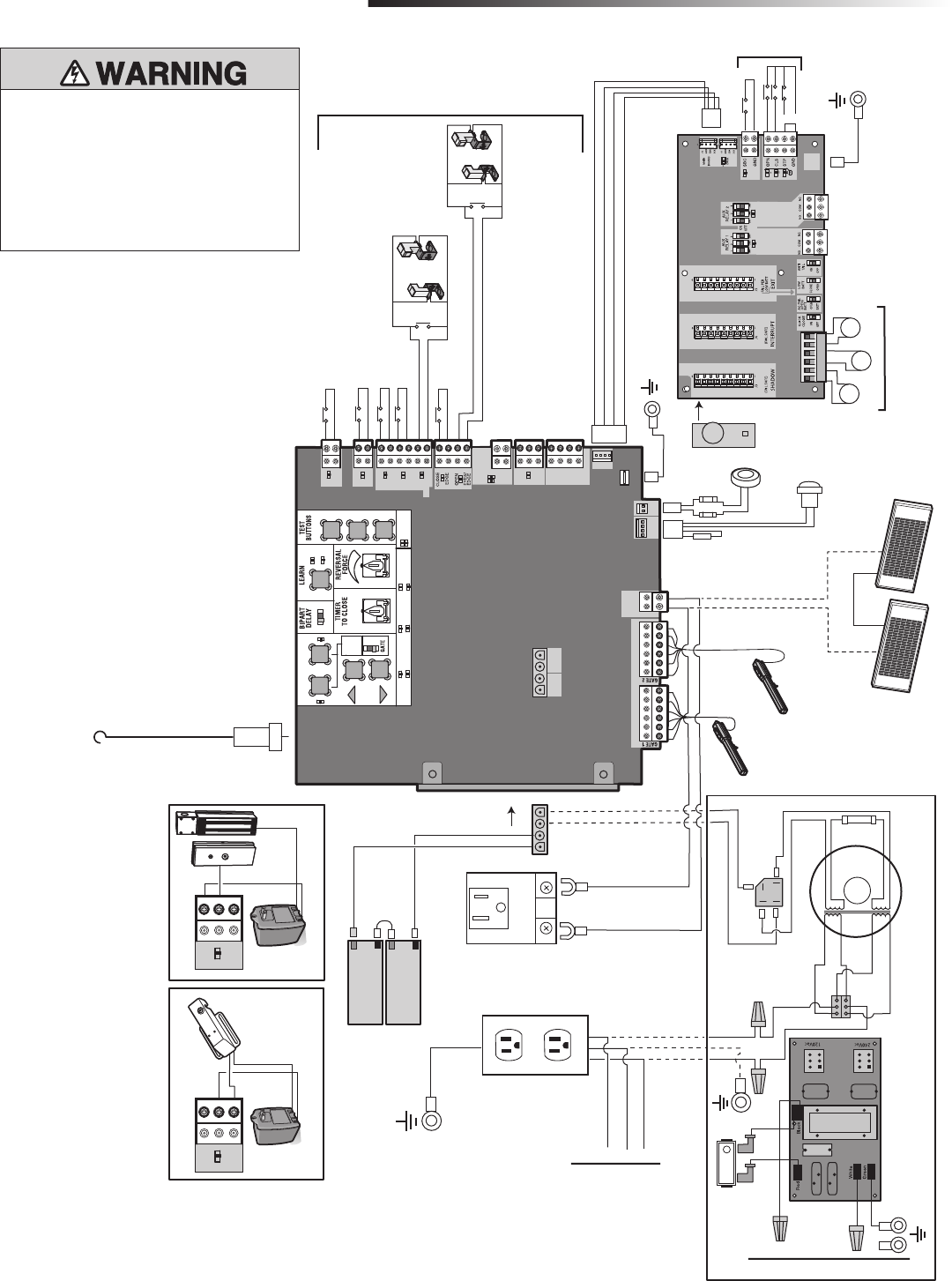
42
To protect against fire and electrocution:
• DISCONNECT power and battery BEFORE
installing or servicing operator.
For continued protection against fire:
• Replace ONLY with fuse of same type and
rating.
STANDARD CONTROL BOX
WIRING DIAGRAMS
Attach to Outlet
Metal Chassis
With a Single Screw
SET OPEN SET CLOSE
MOVE
GATE
OFF
5
10
60
180 MIN MAX
(SECONDS
OFF ON
OPEN CLOSE STOP
NPUT POWER
BATT CHARG NG
T MER
GATE MOV NG
BATT LOW
ACC PWR OVLD
D AGNOST C
CODES
STATUS:
SBC
“F RE
DEPT”
OPEN
EX T
SHADOW
CLOSE
EYES/
NTERRUPT
LOCK
N O
COM
N C
+
+
ACCESSORY
POWER
ON SW
EXP
BOARD
XM TTER
NETWORK
PRESS &
RELEASE
TO BEG N
SETUP
CLA S 2 SU PLY
24 VO TS
1
LMT
2
+ +
J5
+ -
SOLAR /
CHARGER
Photoelectric Sensors
Photoelectric Sensors
Edge
Edge
J15
Field Wiring
EXPANSION BOARD
Yellow
Blue
Black
Red
White/Black
White
White/Black
White
+ -
BATT - +
DC
POWER
D RESET ALARM
Piezo Alarm
White
Wh te
Purple
Reset Switch
Red
Black
GROUND
BR GRN WT YE BLU RED BR GRN WT YE BLU RED
Loop Detector
Field Wiring
Wire Loop
Wire Loop
Wire Loop
Field Wiring
N.C.
Brown
Purple
Transformer 200 VA
+
-
-Bridge Rectier
Wire Nut
Gray
Blue
12V 7AH Battery
Black
Red
12V 7AH Battery
To J15
Primary Operator
Secondary Operator
Black Red
Yellow
White
Red
Orange
Two 12V Solar Panels
in Series +--
+
Black
Red
N
GND
GND
L
N
Input Power Connection
Input Power Connection
EMI FILTER/SURGE PROTECTION BOARD
L
Switch/5A Breaker
Tranformer Run Kit (Optional)
Accessory Power
Outlets
Attach to Metal Chassis
Black
Black
Red
White
Ground
Transformer
Black
Red
Connect Outlets
to Transformer
Kit (If Used)
LOCK
N O
COM
N C
Maglock
(Optional)
(not provided)
LOCK
N O
COM
N C
Solenoid Lock
(Optional)
(not provided)
GROUND
Attach to Outlet Metal Chassis
With a Single Screw
Antenna
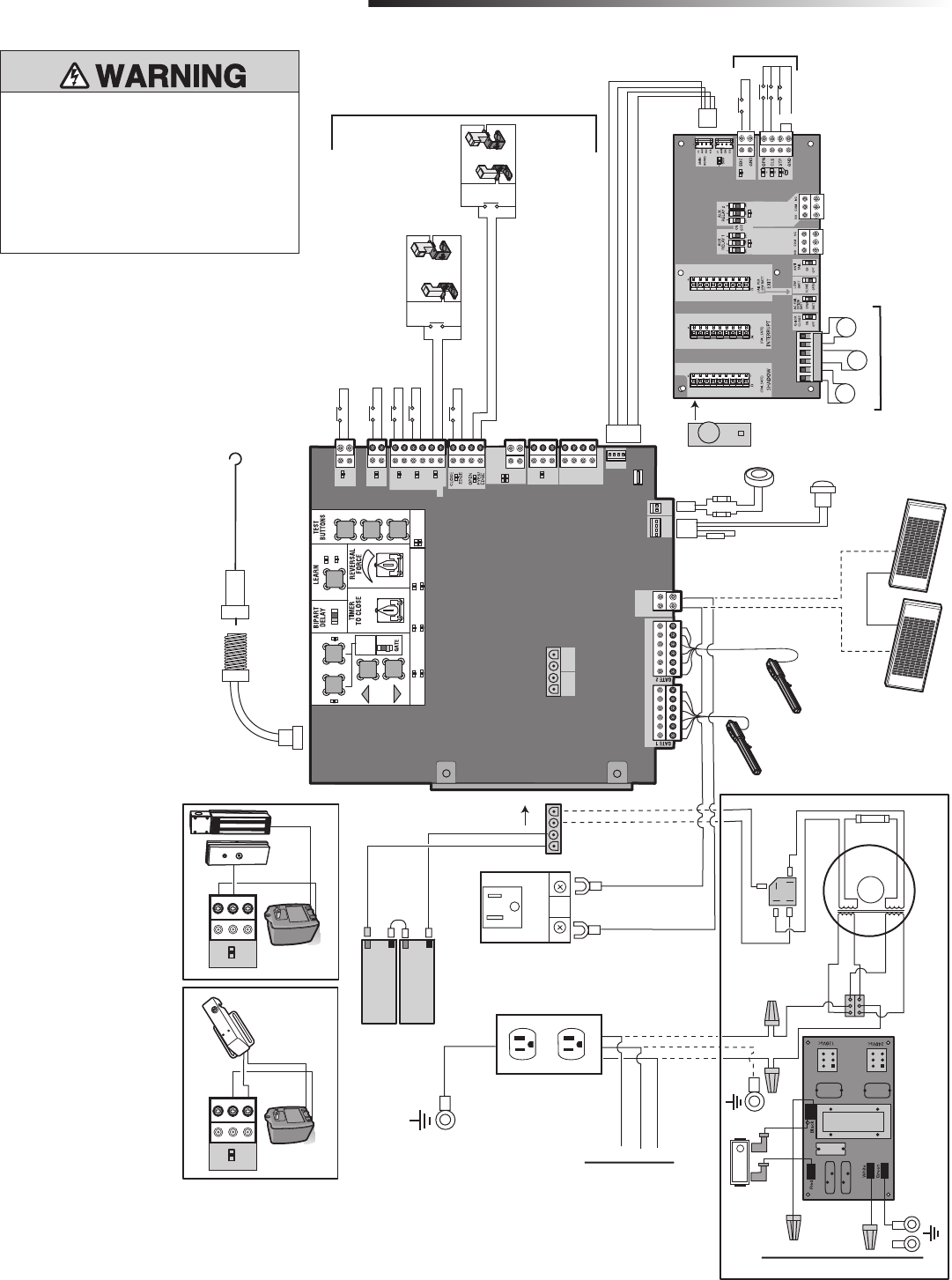
43
SET OPEN SET CLOSE
MOVE
GATE
OFF
5
10
60
180 MIN MAX
(SECONDS
OFF ON
OPEN CLOSE STOP
NPUT POWER
BATT CHARG NG
T MER
GATE MOV NG
BATT LOW
ACC PWR OVLD
D AGNOST C
CODES
STATUS:
SBC
“F RE
DEPT”
OPEN
EX T
SHADOW
CLOSE
EYES/
NTERRUPT
LOCK
N O
COM
N C
+
+
ACCESSORY
POWER
ON SW
EXP
BOARD
XM TTER
NETWORK
PRESS &
RELEASE
O BEG N
SETUP
CLA S 2 SU PLY
24 VO TS
1
LMT
2
+ +
J5
+ -
SOLAR /
CHARGER
Coaxial Antenna Cable
Antenna
Photoelectric Sensors
Photoelectric Sensors
Edge
Edge
J15
Field Wiring
EXPANSION BOARD
Yellow
Blue
Black
Red
White/Black
White
White/Black
White
+ -
BATT
- +
DC
POWER
D RESET ALARM
Piezo Alarm
White
White
Purple
Reset Switch
Red
Black
GROUND
BR GRN WT YE BLU RED BR GRN WT YE BLU RED
Loop Detector
Field Wiring
Wire Loop
Wire Loop
Wire Loop
Field Wiring
N.C.
Brown
Purple
Transformer 200 VA
+
-
-Bridge Rectier
Wire Nut
Gray
Blue
12V 7AH Battery
Black
Red
12V 7AH Battery
To J15
Primary Operator
Secondary Operator
Black Red
Yellow
White
Red
Orange
Two 12V Solar Panels
in Series +--
+
Black
Red
N
GND
GND
L
N
Input Power Connection
Input Power Connection
EMI FILTER/SURGE PROTECTION BOARD
L
Switch/5A Breaker
Tranformer Run Kit (Optional)
Accessory Power
Outlets
Attach to Metal Chassis
Black
Black
Red
White
Ground
Transformer
Black
Red
Connect Outlets
to Transformer
Kit (If Used)
LOCK
N O
COM
N C
Maglock
(Optional)
(not provided)
LOCK
N O
COM
N C
Solenoid Lock
(Optional)
(not provided)
LARGE METAL CONTROL BOX (XLM)
WIRING DIAGRAMS
To protect against fire and electrocution:
• DISCONNECT power and battery BEFORE
installing or servicing operator.
For continued protection against fire:
• Replace ONLY with fuse of same type and
rating.
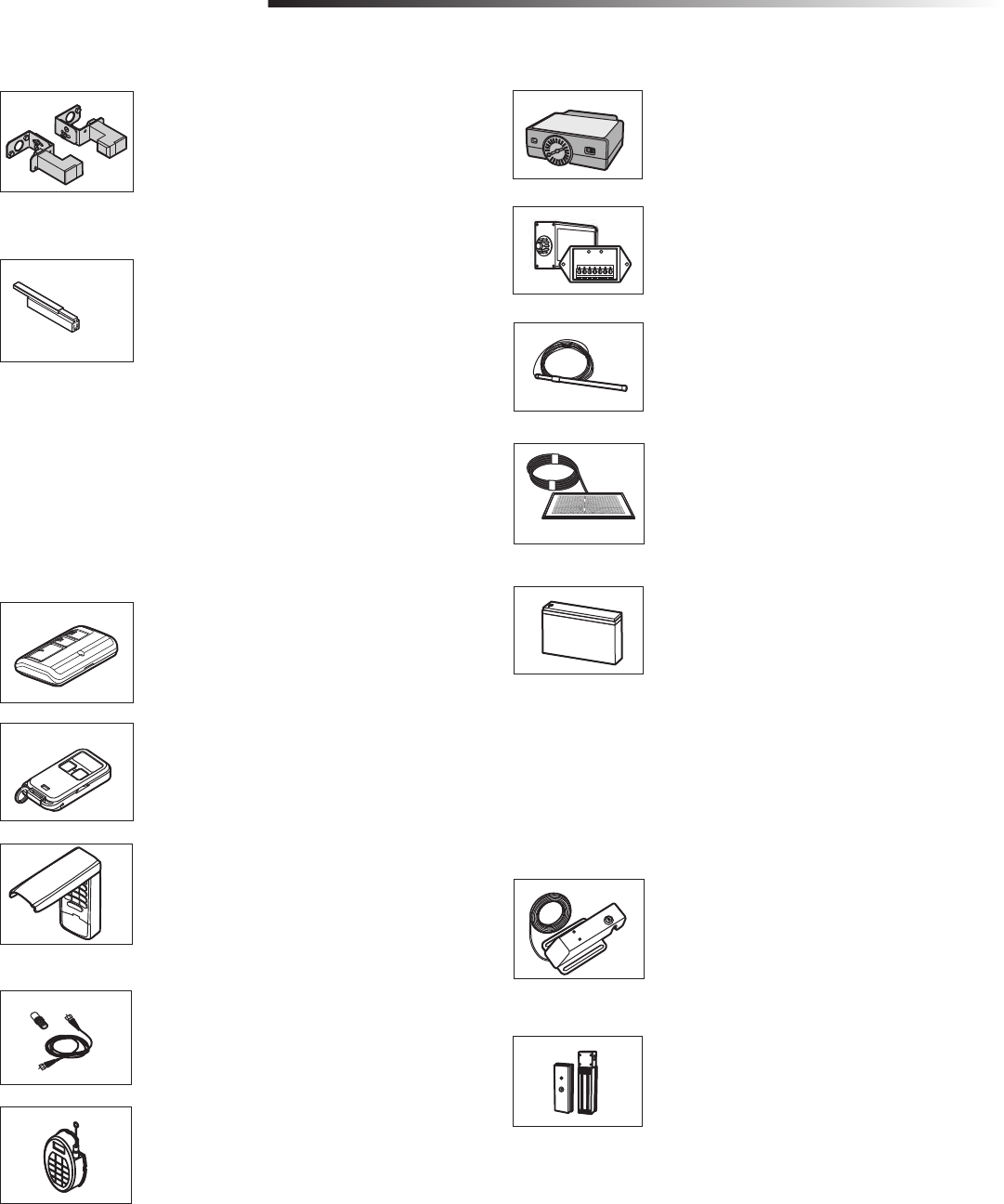
44
PHOTOELECTRIC SENSORS (NON-CONTACT)
The photoelectric sensors are designed to detect an obstacle in the
path of the electronic beam and stop the operator. Includes
mounting brackets.
Models AOMRON E3K-R10K4-NR (retro-reflective), RETROAB
60-2728 (retro-reflective), CPS-UN4 (through beam)
SENSING EDGE (2-WIRE, NON-MONITORED,
CONTACT)
Sensing edges can detect an obstacle upon contact and stop the
operator.
Models G65MG0204, G65MG0205, G65MGR205, and
G65MGS205
SENSING EDGE CHANNEL
Mounting channel for all MG020 type edges.
Model G65ME120C5
ENTRAPMENT PROTECTION DEVICES
MISCELLANEOUS
REMOTE ANTENNA EXTENSION KIT
The remote antenna extension kit allows the antenna to be
remotely installed.
Model 86LM
WIRELESS ACCESS CONTROL RECEIVER
Access control receiver for up to 450 remote controls.
Model STAR450-315
PLUG-IN LOOP DETECTOR
Low power. Conveniently plugs into existing control board.
Model LOOPDETLM
LOOP DETECTOR
Low power loop detectors mounted and wired separately inside
control box.
Model LD7LP
VEHICLE SENSING PROBE
The vehicle sensing probe is buried in the ground and can detect a
car as it approaches and will then open the gate.
Model CP3
SOLAR PANEL KIT - 10 WATT
This kit is to replace or add a solar panel to the operator
application. Up to four solar panels can be connected to the
operator.
Model SOLPNL10W12V (requires 2 minimum)
BATTERY FOR GATE ACCESS SYSTEMS
Gate access system batteries replace or upgrade the gate operator
batteries.
Model 29-NP712 (standard 7 AMP-Hour Battery, 12 Vdc, to
replace original batteries provided with operator, reuse existing
harnesses)
Model A12330SGLPK (upgrade 33 AMP-Hour Battery, 12 Vdc,
includes 33AH harness. Ideal for solar applications and extended
battery backup). For use with Large Metal Control Box ONLY.
Two identical 12 Vdc batteries are required for each gate
operator. Do not mix 7AH and 33AH batteries within a gate
operator.
SOLENOID GATE LOCK
The automatic gate lock is a solenoid-driven lock that
automatically unlocks when the gate is open and locks when the
gate is closed. Can be mounted onto a gate or post. Can be
released in case of emergency.
Models GC824 (115 Vac) and GC824-12 (12/24 Vac/dc)
MAGNETIC GATE LOCK
Outdoor magnetic lock, transformer, junction box, mounting plate
and hardware. Not for use with Solar Applications. Must be
powered separately.
Model MG1300
TRANSFORMER RUN KIT (OPTIONAL
Model LA500HDTKITSTD (for Standard Control Box)
Model LA500HDTKITXLM (for Large Metal Control Box)
MISCELLANEOUS
ACCESSORIES
REMOTE CONTROLS
Chamberlain offers a variety of LiftMaster remote controls to satisfy your application needs.
Single-button to 4-button, visor or key chain. The following remote controls are compatible
with operators manufactured by Chamberlain after 1993. Contact your authorized LiftMaster
dealer for additional details and options.
3-BUTTON REMOTE CONTROL
The 3-button remote control can be programmed to control the
operator. Includes visor clip.
Model 893MAX
3-BUTTON MINI-REMOTE CONTROL
The 3-button remote control can be programmed to control the
operator. Includes key ring and fastening strip.
Model 890MAX
KEYLESS ENTRY
Enables homeowner to operate gate operator from outside by
entering a 4-digit code on a specially designed keypad.
Model 877MAX

45
WARRANTY
LIFTMASTER 3 YEAR RESIDENTIAL / 2 YEAR COMMERCIAL LIMITED WARRANTY
The Chamberlain Group, Inc. (“Seller”) warrants to the first purchaser of this product, for the structure in which this product is originally installed, that it is free from defect in
materials and/or workmanship for a period of 3 year residential/ 2 year commercial from the date of purchase [and that the LA500™ and LA500CONT™ are free from
defect in materials and/or workmanship for a period of 3 year residential/ 2 year commercial from the date of purchase]. The proper operation of this product is dependent
on your compliance with the instructions regarding installation, operation, maintenance and testing. Failure to comply strictly with those instructions will void this limited
warranty in its entirety.
If, during the limited warranty period, this product appears to contain a defect covered by this limited warranty, call 1-800-528-2806, toll free, before dismantling this
product. Then send this product, pre-paid and insured, to our service center for warranty repair. You will be advised of shipping instructions when you call. Please include a
brief description of the problem and a dated proof-of-purchase receipt with any product returned for warranty repair. Products returned to Seller for warranty repair, which
upon receipt by Seller are confirmed to be defective and covered by this limited warranty, will be repaired or replaced (at Seller’s sole option) at no cost to you and returned
pre-paid. Defective parts will be repaired or replaced with new or factory-rebuilt parts at Seller’s sole option.
ALL IMPLIED WARRANTIES FOR THE PRODUCT, INCLUDING BUT NOT LIMITED TO ANY IMPLIED WARRANTIES OF
MERCHANTABILITY AND FITNESS FOR A PARTICULAR PURPOSE, ARE LIMITED IN DURATION TO THE 3 YEAR RESIDENTIAL/
2 YEAR COMMERCIAL LIMITED WARRANTY PERIOD SET FORTH ABOVE [EXCEPT THE IMPLIED WARRANTIES WITH RESPECT
TO THE LA500™ AND LA500CONT™, WHICH ARE LIMITED IN DURATION TO THE 3 YEAR RESIDENTIAL/ 2 YEAR
COMMERCIAL LIMITED WARRANTY PERIOD FOR THE LA500™ AND LA500CONT™], AND NO IMPLIED WARRANTIES WILL
EXIST OR APPLY AFTER SUCH PERIOD. Some states do not allow limitations on how long an implied warranty lasts,
so the above limitation may not apply to you. THIS LIMITED WARRANTY DOES NOT COVER NON-DEFECT DAMAGE,
DAMAGE CAUSED BY IMPROPER INSTALLATION, OPERATION OR CARE (INCLUDING, BUT NOT LIMITED TO ABUSE, MISUSE,
FAILURE TO PROVIDE REASONABLE AND NECESSARY MAINTENANCE, UNAUTHORIZED REPAIRS OR ANY ALTERATIONS TO
THIS PRODUCT), LABOR CHARGES FOR REINSTALLING A REPAIRED OR REPLACED UNIT, OR REPLACEMENT OF BATTERIES.
THIS LIMITED WARRANTY DOES NOT COVER ANY PROBLEMS WITH, OR RELATING TO, THE GATE OR GATE HARDWARE,
INCLUDING BUT NOT LIMITED TO THE GATE SPRINGS, GATE ROLLERS, GATE ALIGNMENT OR HINGES. THIS LIMITED
WARRANTY ALSO DOES NOT COVER ANY PROBLEMS CAUSED BY INTERFERENCE. ANY SERVICE CALL THAT DETERMINES
THE PROBLEM HAS BEEN CAUSED BY ANY OF THESE ITEMS COULD RESULT IN A FEE TO YOU.
UNDER NO CIRCUMSTANCES SHALL SELLER BE LIABLE FOR CONSEQUENTIAL, INCIDENTAL OR SPECIAL DAMAGES ARISING
IN CONNECTION WITH USE, OR INABILITY TO USE, THIS PRODUCT. IN NO EVENT SHALL SELLER’S LIABILITY FOR BREACH
OF WARRANTY, BREACH OF CONTRACT, NEGLIGENCE OR STRICT LIABILITY EXCEED THE COST OF THE PRODUCT COVERED
HEREBY. NO PERSON IS AUTHORIZED TO ASSUME FOR US ANY OTHER LIABILITY IN CONNECTION WITH THE SALE OF THIS
PRODUCT.
Some states do not allow the exclusion or limitation of consequential, incidental or special damages, so the above limitation or exclusion may not apply to you. This limited
warranty gives you specific legal rights, and you may also have other rights which vary from state to state.
01-36213 © 2011, The Chamberlain Group, Inc. – All Rights Reserved
845 Larch Avenue
Elmhurst, Illinois 60126-1196