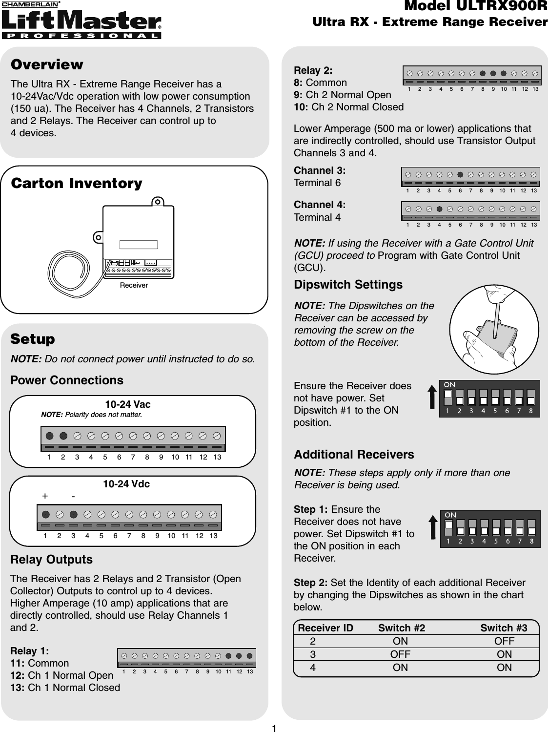
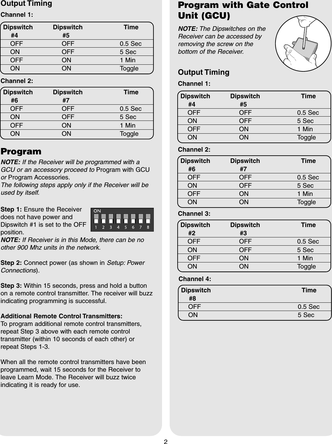
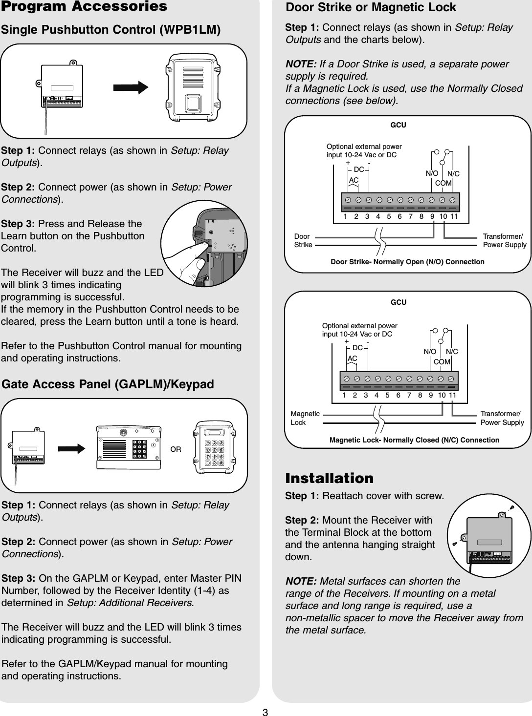
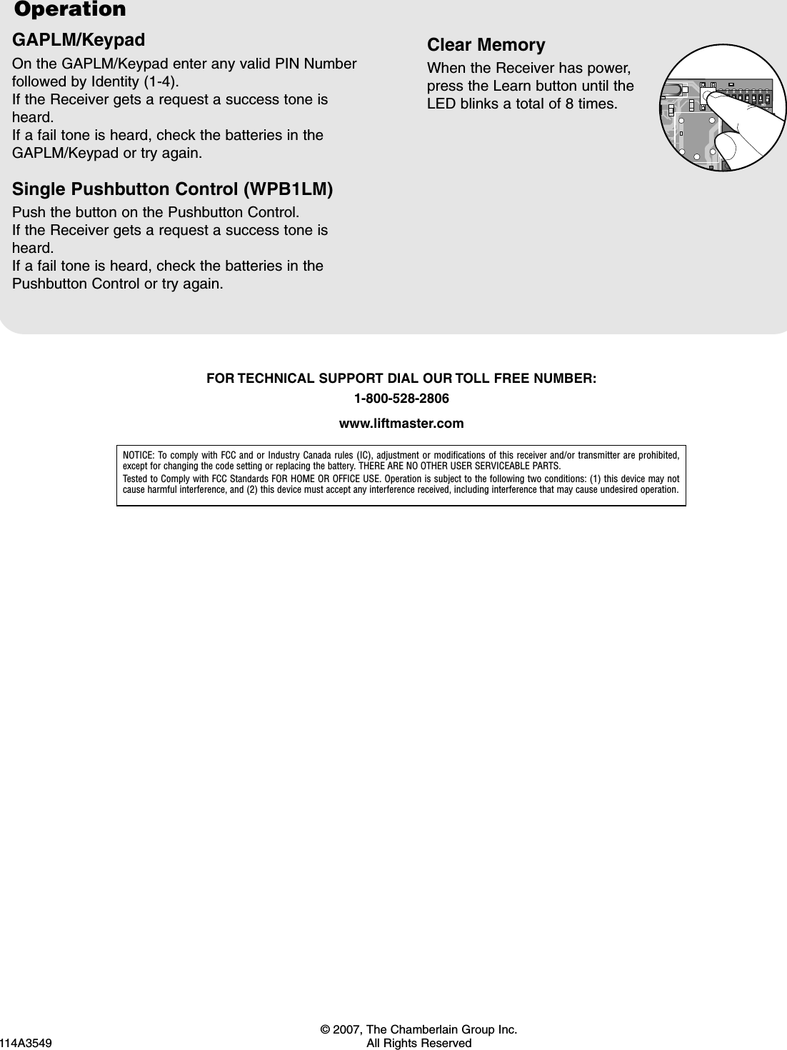
Chamberlain Wireless RX900 ULTRX900R - Extreme Range Transceiver User Manual

Chamberlain Wireless Products Inc. ULTRX900R - Extreme Range Transceiver

User Manual

Carton InventoryOverviewThe Ultra RX - Extreme Range Receiver has a 10-24Vac/Vdc operation with low power consumption(150 ua). The Receiver has 4 Channels, 2 Transistorsand 2 Relays. The Receiver can control up to 4 devices.1ReceiverModel ULTRX900RUltra RX - Extreme Range ReceiverSetup1 3 2  4 5 6 7 8 9 10 11 12  13 10-24 Vac1 3 2  4 5 6 7 8 9 10 11 12  13 - + 10-24 VdcNOTE: Polarity does not matter.Power ConnectionsRelay OutputsThe Receiver has 2 Relays and 2 Transistor (OpenCollector) Outputs to control up to 4 devices.Higher Amperage (10 amp) applications that aredirectly controlled, should use Relay Channels 1 and 2.Relay 1:11: Common12: Ch 1 Normal Open13: Ch 1 Normal Closed1 3 2  4 5 6 7 8 9 10 11 12  13 Relay 2:8: Common9: Ch 2 Normal Open10: Ch 2 Normal ClosedLower Amperage (500 ma or lower) applications thatare indirectly controlled, should use Transistor OutputChannels 3 and 4.Channel 3:Terminal 6Channel 4:Terminal 41 3 2  4 5 6 7 8 9 10 11 12  13 1 3 2  4 5 6 7 8 9 10 11 12  13 1 3 2  4 5 6 7 8 9 10 11 12  13 Dipswitch SettingsNOTE: If using the Receiver with a Gate Control Unit(GCU) proceed to Program with Gate Control Unit(GCU).NOTE: The Dipswitches on theReceiver can be accessed byremoving the screw on thebottom of the Receiver.Ensure the Receiver doesnot have power. SetDipswitch #1 to the ONposition.NOTE: These steps apply only if more than oneReceiver is being used.Step 1: Ensure theReceiver does not havepower. Set Dipswitch #1 tothe ON position in eachReceiver.Step 2: Set the Identity of each additional Receiverby changing the Dipswitches as shown in the chartbelow.Receiver ID Switch #2 Switch #32 ON OFF3 OFF ON4ON ONAdditional ReceiversNOTE: Do not connect power until instructed to do so.
2Output TimingDipswitch Dipswitch Time#4 #5OFF OFF 0.5 SecON OFF 5 SecOFF ON 1 MinON ON ToggleChannel 1:Dipswitch Dipswitch Time#6 #7OFF OFF 0.5 SecON OFF 5 SecOFF ON 1 MinON ON ToggleChannel 2:ProgramNOTE: If the Receiver will be programmed with aGCU or an accessory proceed to Program with GCUor Program Accessories.The following steps apply only if the Receiver will beused by itself.Step 1: Ensure the Receiverdoes not have power andDipswitch #1 is set to the OFFposition.NOTE: If Receiver is in this Mode, there can be noother 900 Mhz units in the network.Step 2: Connect power (as shown in Setup: PowerConnections).Step 3: Within 15 seconds, press and hold a buttonon a remote control transmitter. The receiver will buzzindicating programming is successful.Additional Remote Control Transmitters:To program additional remote control transmitters,repeat Step 3 above with each remote controltransmitter (within 10 seconds of each other) orrepeat Steps 1-3.When all the remote control transmitters have beenprogrammed, wait 15 seconds for the Receiver toleave Learn Mode. The Receiver will buzz twiceindicating it is ready for use.Output TimingDipswitch Dipswitch Time#4 #5OFF OFF 0.5 SecON OFF 5 SecOFF ON 1 MinON ON ToggleChannel 1:Dipswitch Dipswitch Time#6 #7OFF OFF 0.5 SecON OFF 5 SecOFF ON 1 MinON ON ToggleChannel 2:Dipswitch Dipswitch Time#2 #3OFF OFF 0.5 SecON OFF 5 SecOFF ON 1 MinON ON ToggleChannel 3:Dipswitch Time#8OFF 0.5 SecON 5 SecChannel 4:Program with Gate ControlUnit (GCU)NOTE: The Dipswitches on theReceiver can be accessed byremoving the screw on thebottom of the Receiver.
3Door Strike or Magnetic LockStep 1: Connect relays (as shown in Setup: RelayOutputs and the charts below).NOTE: If a Door Strike is used, a separate powersupply is required.If a Magnetic Lock is used, use the Normally Closedconnections (see below).132 4567891011DCAC+-COMN/CDoor StrikeTransformer/Power SupplyOptional external power input 10-24 Vac or DCDoor Strike- Normally Open (N/O) Connection N/O1324567891011+-COMN/CMagneticLockTransformer/Power SupplyMagnetic Lock- Normally Closed (N/C) Connection DCACOptional external power input 10-24 Vac or DCN/OGCUGCUProgram AccessoriesSingle Pushbutton Control (WPB1LM)Step 1: Connect relays (as shown in Setup: RelayOutputs).Step 2: Connect power (as shown in Setup: PowerConnections).Step 3: Press and Release theLearn button on the PushbuttonControl.The Receiver will buzz and the LEDwill blink 3 times indicatingprogramming is successful.If the memory in the Pushbutton Control needs to becleared, press the Learn button until a tone is heard.Refer to the Pushbutton Control manual for mountingand operating instructions. Gate Access Panel (GAPLM)/KeypadStep 1: Connect relays (as shown in Setup: RelayOutputs).Step 2: Connect power (as shown in Setup: PowerConnections).Step 3: On the GAPLM or Keypad, enter Master PINNumber, followed by the Receiver Identity (1-4) asdetermined in Setup: Additional Receivers.The Receiver will buzz and the LED will blink 3 timesindicating programming is successful.Refer to the GAPLM/Keypad manual for mountingand operating instructions.1 2  3 4 5 6 7 8 9  0 # a c  ORInstallationStep 1: Reattach cover with screw.Step 2: Mount the Receiver withthe Terminal Block at the bottomand the antenna hanging straightdown.NOTE: Metal surfaces can shorten therange of the Receivers. If mounting on a metalsurface and long range is required, use a non-metallic spacer to move the Receiver away fromthe metal surface.
© 2007, The Chamberlain Group Inc.114A3549 All Rights ReservedNOTICE: To comply with FCC and or Industry Canada rules (IC), adjustment or modifications of this receiver and/or transmitter are prohibited,except for changing the code setting or replacing the battery. THERE ARE NO OTHER USER SERVICEABLE PARTS.Tested to Comply with FCC Standards FOR HOME OR OFFICE USE. Operation is subject to the following two conditions: (1) this device may notcause harmful interference, and (2) this device must accept any interference received, including interference that may cause undesired operation.FOR TECHNICAL SUPPORT DIAL OUR TOLL FREE NUMBER:1-800-528-2806www.liftmaster.comOperationGAPLM/KeypadOn the GAPLM/Keypad enter any valid PIN Numberfollowed by Identity (1-4).If the Receiver gets a request a success tone isheard.If a fail tone is heard, check the batteries in theGAPLM/Keypad or try again.Single Pushbutton Control (WPB1LM)Push the button on the Pushbutton Control.If the Receiver gets a request a success tone isheard.If a fail tone is heard, check the batteries in thePushbutton Control or try again.Clear MemoryWhen the Receiver has power,press the Learn button until theLED blinks a total of 8 times.ON1234567

Navigation menu