Chamberlain Wireless RX900 ULTRX900R - Extreme Range Transceiver User Manual
Chamberlain Wireless Products Inc. ULTRX900R - Extreme Range Transceiver
User Manual
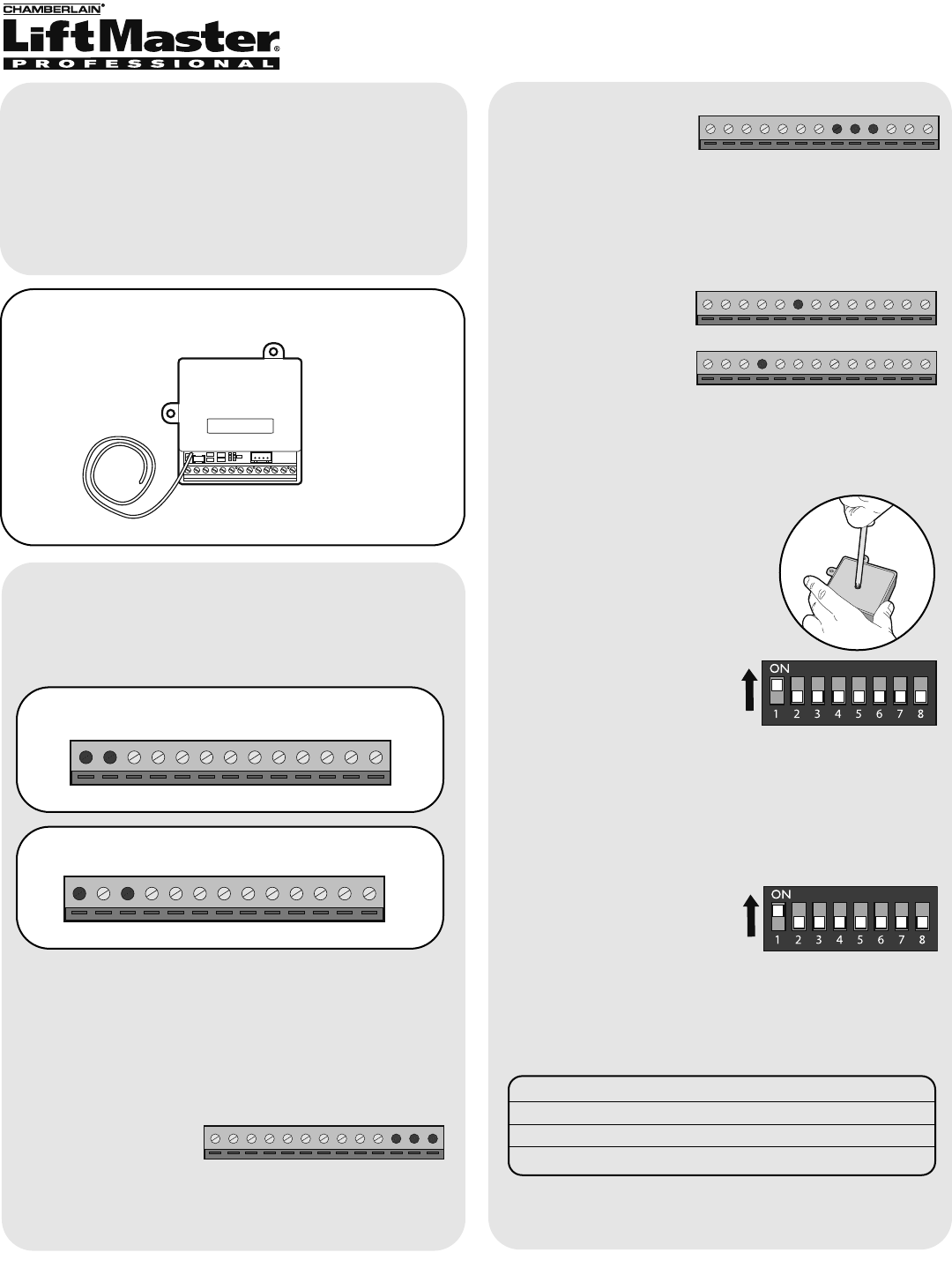
Carton Inventory
Overview
The Ultra RX - Extreme Range Receiver has a
10-24Vac/Vdc operation with low power consumption
(150 ua). The Receiver has 4 Channels, 2 Transistors
and 2 Relays. The Receiver can control up to
4 devices.
1
Receiver
Model ULTRX900R
Ultra RX - Extreme Range Receiver
Setup
1 3 2 4 5 6 7 8 9 10 11 12 13
10-24 Vac
1 3 2 4 5 6 7 8 9 10 11 12 13
-
+
10-24 Vdc
NOTE: Polarity does not matter.
Power Connections
Relay Outputs
The Receiver has 2 Relays and 2 Transistor (Open
Collector) Outputs to control up to 4 devices.
Higher Amperage (10 amp) applications that are
directly controlled, should use Relay Channels 1
and 2.
Relay 1:
11: Common
12: Ch 1 Normal Open
13: Ch 1 Normal Closed
1 3 2 4 5 6 7 8 9 10 11 12 13
Relay 2:
8: Common
9: Ch 2 Normal Open
10: Ch 2 Normal Closed
Lower Amperage (500 ma or lower) applications that
are indirectly controlled, should use Transistor Output
Channels 3 and 4.
Channel 3:
Terminal 6
Channel 4:
Terminal 4
1 3 2 4 5 6 7 8 9 10 11 12 13
1 3 2 4 5 6 7 8 9 10 11 12 13
1 3 2 4 5 6 7 8 9 10 11 12 13
Dipswitch Settings
NOTE: If using the Receiver with a Gate Control Unit
(GCU) proceed to Program with Gate Control Unit
(GCU).
NOTE: The Dipswitches on the
Receiver can be accessed by
removing the screw on the
bottom of the Receiver.
Ensure the Receiver does
not have power. Set
Dipswitch #1 to the ON
position.
NOTE: These steps apply only if more than one
Receiver is being used.
Step 1: Ensure the
Receiver does not have
power. Set Dipswitch #1 to
the ON position in each
Receiver.
Step 2: Set the Identity of each additional Receiver
by changing the Dipswitches as shown in the chart
below.
Receiver ID Switch #2 Switch #3
2 ON OFF
3 OFF ON
4ON ON
Additional Receivers
NOTE: Do not connect power until instructed to do so.
2
Output Timing
Dipswitch Dipswitch Time
#4 #5
OFF OFF 0.5 Sec
ON OFF 5 Sec
OFF ON 1 Min
ON ON Toggle
Channel 1:
Dipswitch Dipswitch Time
#6 #7
OFF OFF 0.5 Sec
ON OFF 5 Sec
OFF ON 1 Min
ON ON Toggle
Channel 2:
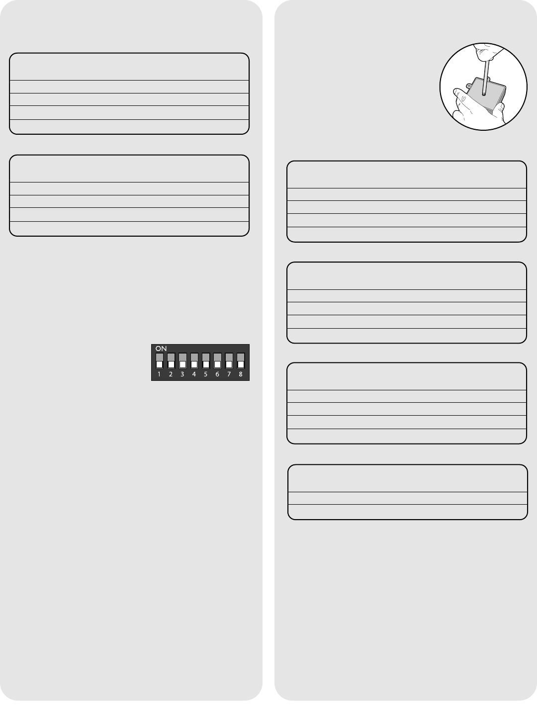
Program
NOTE: If the Receiver will be programmed with a
GCU or an accessory proceed to Program with GCU
or Program Accessories.
The following steps apply only if the Receiver will be
used by itself.
Step 1: Ensure the Receiver
does not have power and
Dipswitch #1 is set to the OFF
position.
NOTE: If Receiver is in this Mode, there can be no
other 900 Mhz units in the network.
Step 2: Connect power (as shown in Setup: Power
Connections).
Step 3: Within 15 seconds, press and hold a button
on a remote control transmitter. The receiver will buzz
indicating programming is successful.
Additional Remote Control Transmitters:
To program additional remote control transmitters,
repeat Step 3 above with each remote control
transmitter (within 10 seconds of each other) or
repeat Steps 1-3.
When all the remote control transmitters have been
programmed, wait 15 seconds for the Receiver to
leave Learn Mode. The Receiver will buzz twice
indicating it is ready for use.
Output Timing
Dipswitch Dipswitch Time
#4 #5
OFF OFF 0.5 Sec
ON OFF 5 Sec
OFF ON 1 Min
ON ON Toggle
Channel 1:
Dipswitch Dipswitch Time
#6 #7
OFF OFF 0.5 Sec
ON OFF 5 Sec
OFF ON 1 Min
ON ON Toggle
Channel 2:
Dipswitch Dipswitch Time
#2 #3
OFF OFF 0.5 Sec
ON OFF 5 Sec
OFF ON 1 Min
ON ON Toggle
Channel 3:
Dipswitch Time
#8
OFF 0.5 Sec
ON 5 Sec
Channel 4:
Program with Gate Control
Unit (GCU)
NOTE: The Dipswitches on the
Receiver can be accessed by
removing the screw on the
bottom of the Receiver.
3
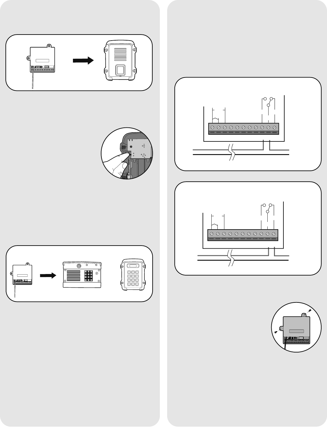
Door Strike or Magnetic Lock
Step 1: Connect relays (as shown in Setup: Relay
Outputs and the charts below).
NOTE: If a Door Strike is used, a separate power
supply is required.
If a Magnetic Lock is used, use the Normally Closed
connections (see below).
132 4567891011
DC
AC
+-
COM
N/C
Door
Strike
Transformer/
Power Supply
Optional external power
input 10-24 Vac or DC
Door Strike- Normally Open (N/O) Connection
N/O
1324567891011
+-
COM
N/C
Magnetic
Lock
Transformer/
Power Supply
Magnetic Lock- Normally Closed (N/C) Connection
DC
AC
Optional external power
input 10-24 Vac or DC
N/O
GCU
GCU
Program Accessories
Single Pushbutton Control (WPB1LM)
Step 1: Connect relays (as shown in Setup: Relay
Outputs).
Step 2: Connect power (as shown in Setup: Power
Connections).
Step 3: Press and Release the
Learn button on the Pushbutton
Control.
The Receiver will buzz and the LED
will blink 3 times indicating
programming is successful.
If the memory in the Pushbutton Control needs to be
cleared, press the Learn button until a tone is heard.
Refer to the Pushbutton Control manual for mounting
and operating instructions.
Gate Access Panel (GAPLM)/Keypad
Step 1: Connect relays (as shown in Setup: Relay
Outputs).
Step 2: Connect power (as shown in Setup: Power
Connections).
Step 3: On the GAPLM or Keypad, enter Master PIN
Number, followed by the Receiver Identity (1-4) as
determined in Setup: Additional Receivers.
The Receiver will buzz and the LED will blink 3 times
indicating programming is successful.
Refer to the GAPLM/Keypad manual for mounting
and operating instructions.
1
2 3
4
5 6
7 8 9
0 #
a c
OR
Installation
Step 1: Reattach cover with screw.
Step 2: Mount the Receiver with
the Terminal Block at the bottom
and the antenna hanging straight
down.
NOTE: Metal surfaces can shorten the
range of the Receivers. If mounting on a metal
surface and long range is required, use a
non-metallic spacer to move the Receiver away from
the metal surface.

© 2007, The Chamberlain Group Inc.
114A3549 All Rights Reserved
NOTICE: To comply with FCC and or Industry Canada rules (IC), adjustment or modifications of this receiver and/or transmitter are prohibited,
except for changing the code setting or replacing the battery. THERE ARE NO OTHER USER SERVICEABLE PARTS.
Tested to Comply with FCC Standards FOR HOME OR OFFICE USE. Operation is subject to the following two conditions: (1) this device may not
cause harmful interference, and (2) this device must accept any interference received, including interference that may cause undesired operation.
FOR TECHNICAL SUPPORT DIAL OUR TOLL FREE NUMBER:
1-800-528-2806
www.liftmaster.com
Operation
GAPLM/Keypad
On the GAPLM/Keypad enter any valid PIN Number
followed by Identity (1-4).
If the Receiver gets a request a success tone is
heard.
If a fail tone is heard, check the batteries in the
GAPLM/Keypad or try again.
Single Pushbutton Control (WPB1LM)
Push the button on the Pushbutton Control.
If the Receiver gets a request a success tone is
heard.
If a fail tone is heard, check the batteries in the
Pushbutton Control or try again.
Clear Memory
When the Receiver has power,
press the Learn button until the
LED blinks a total of 8 times.
ON
1234567