Chamk lnorated SG700BT SG700BT Wireless Linear Imager Bar Code Scanner User Manual BT programming menu V3 9
Champtek lncorporated SG700BT Wireless Linear Imager Bar Code Scanner BT programming menu V3 9
UserManual.wiki
>
Chamk lnorated
>
SG700BT User Manual
User Manual
Navigation menu
Upload a User Manual
Namespaces
Wiki Guide
HTML
PDF
Info
Views
User Manual
Discussion / Help
Navigation
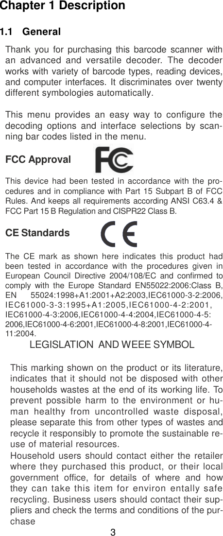

![5.4 Code 128 Parameters A> Reading Type UCC/EA1-128 Enable %0F4 4 <Enable’]C1’Code Format> %0 F 2 2 <Enable Code128 Group Separators(GS)> <UCC/EA1-128 Disable> %0F40 Disable‘]C1‘Code Format %0F20 %0F1 1 Disable Code128 Group Separators(GS) B> Check Digit Transmission Do Not Calculate Check Digit %0F10 %0F N1 Calculate Check Digit & Transmit <Calculate Check Digit& Not Transmit> %0FN7 %0FN5 C> Append FNC2 ON %0F8 8 <OFF> %0F80 28](https://usermanual.wiki/Chamk-lnorated/SG700BT/User-Guide-2722348-Page-32.png)

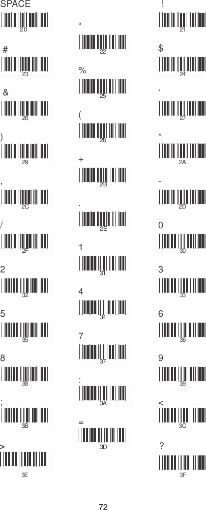
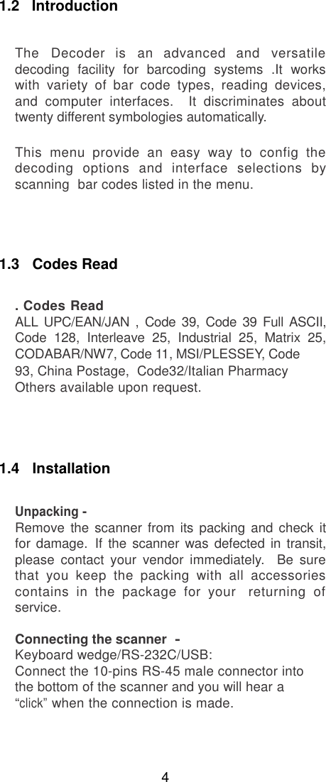
![@ A 40 B 41 C 42 D 43 E 44 F 45 G 46 H 47 I 48 J 49 K 4A L 4B M 4C N 4D O 4E P 4F Q 5 0 R 51 S 52 T 5 3 U 54 V 55 W 56 X 57 Y 58 Z 59 [ 5A \ 5B ] 5C ^ 5D _ 5E 5F 73](https://usermanual.wiki/Chamk-lnorated/SG700BT/User-Guide-2722348-Page-77.png)