Chamk lnorated SG700BT SG700BT Wireless Linear Imager Bar Code Scanner User Manual BT programming menu V3 9
Champtek lncorporated SG700BT Wireless Linear Imager Bar Code Scanner BT programming menu V3 9
User Manual


The Federal Communication Commission Statement
This equipment has been tested and found to comply with the limits for a Class B Digital Device, pursuant to
Part 15 of the FCC rules. These limits are designed to provide reasonable protection against harmful
interference in a residential installation. T
his equipment generates, uses and can radiate radio frequency
energy and, if not installed and used in accordance with the instruction, may cause harmful interference to
radio communication. However, there is no guarantee that interference will not occur
in a particular
installation. If this equipment does cause harmful interference to radio or television reception, which can be
determined by turning the equipment off and on, the user is encouraged to try to correct the interference
by one of more of the following measures: -
- Reorient or relocate the receiving antenna.
- Increase the separation between the equipment and receiver.
-
Connect the equipment into an outlet on a circuit different from that to which the receiver is
connected.
- Consult the dealer or an experienced Radio/TV technician for help.
Use only shielded cables to connect I/O devices to this equipment. You are cautioned that change or
modifications not expressly approved by the party responsible for compliance could void yo
ur authority to
operate the equipment.
THIS DEVICE COMPLIES WITH PART 15 OF FCC RULES. OPERATION IS SUBJECT TO THE
FOLLOWING TWO CONDITIONS:
1
This device may not cause harmful interference and
2 This device must accept any interference received, including interference that may cause undesired
operation.
The antenna used for this transmitter must not be collocated or operation in conjunction
with any other antenna or transmitter.
Notice : The changes or modifications not expressly approved by the party responsible
for compliance could void the user’s authority to operate the equipment.
IMPORTANT NOTE: To comply with the FCC RF exposure compliance requirements, no change
to the antenna or the device is permitted. Any change to the antenna or the device could result
in the device exceeding the RF exposure requirements and void user’s authority to operate
the device.

Programming Menu
V3.9
Notice
The manufacturer shall not be liable for technical or
editorial errors or omissions contained herein; nor
for incidental or consequential damages in
connection with the furnishing, performance or use of
use the publication.
1
Contents
Chapter 1 Description ............................................................ 3
1.1 General ................................................................ 3
1.2 Introduction ......................................................... 4
1.3 Codes Read .......................................................... 4
1.4 Installation ........................................................... 4
1.5 Pin Assig
nment ..................................................... 6
Chapter 2 Configuration - G
eneral
...................................... 8
2.1 Flow Chart ............................................................ 8
2.2 Loop of Programming .......................................... 9
2.3 Factory Default Settings ....................................... 9
2.4 Main Page of Configuration ............................... 10
Chapter 3 Interface and ..................................................... 11
3.1 Interface SeIection ............................................. 11
3.2 Reading Mode Selection .................................... 12
Chapter 4 Communication Parameters ................................. 13
4.1 RS232 Communication Parameters .................... 13
4.2 Keyboard Wedge Mode Parameters .................. 16
4.3 Output Characters Parameters .......................... 17
4.4 Wand Emulation Mode Parameters ................... 19
Chapter 5 Bar Codes & Others ............................................ 20
5.1 SymboIogies Selection ....................................... 20
5.2 UPC/EANI/JAN Parameters ................................. 24
5.3 Code 39 Parameters .......................................... 26
5.4
Code
128 Parameters ......................................... 28
5.5 Interleave 25 Parameters ................................... 30
5.6 IndustriaI 25 Parameters .................................... 32
5.7 Matrix 25 Parameters ........................................ 34
5.8 CODABAR/NW7 Parameters .............................. 36
5.9 Code 93 Parameters ........................................... 38
5.10 Code 11 Parameters ........................................... 40
5.11 MSI/PLESSEY Code Parameters .......................... 42
5.12
Code
2 of 6 Parameters ...................................... 44
5.13 LCD25 Parameters ............................................. 46
5.14 Telepen Parameters ........................................... 48
5.15 GS1 Databar ...................................................... 50
Chapter 6 Miscellaneous Parameters ................................ 52
6.1 Language Selection ............................................ 52
6.2 Bar Code ID ........................................................ 54
6.3 Reading Level ...................................................... 57
6.4 Accuracy ............................................................. 57
6.5 Buzzer Beep Tone ............................................... 57
6.6 Sensitivity of Continuous Reading Mode .............. 58
6.7 Reverse Output Characters ........................... 59
6.8 Setup Deletion ................................................. 59
2
6.9 Setup Insertion .................................................. 62
6.10 Scanning Line Selection for Multi Parallel lines
modes ........................................................................ 65
Chapter 7 Bluetooth Configuration.................................... 66
7.1 Scanner Mode ..................................................... 66
7.2 Out of Range ....................................................... 67
7.3 Sleep Mode ......................................................... 68
7.4 Batch Mode ......................................................... 68
7.5 Firmware Version ............................................... 69
Appendix
A Decimal Value Table ...................................... 70
Appendix B ASCII Table .................................................... 71
Appendix C Function Key Table ........................................ 75
Appendix D Decimal Value Table II ................................... 76

3
Chapter 1 Description
1.1 General
Thank you for purchasing this barcode scanner with
an advanced and versatile decoder. The decoder
works with variety of barcode types, reading devices,
and computer interfaces. It discriminates over twenty
different symbologies automatically.
This menu provides an easy way to configure the
decoding options and interface selections by scan-
ning bar codes listed in the menu.
FCC Approval
This device had been tested in accordance with the pro-
cedures and in compliance with Part 15 Subpart B of FCC
Rules. And keeps all requirements according ANSI C63.4 &
FCC Part 15 B Regulation and CISPR22 Class B.
CE Standards
The CE mark as shown here indicates this product had
been tested in accordance with the procedures given in
European Council Directive 2004/108/EC and confirmed to
comply with the Europe Standard EN55022:2006:Class B,
EN 55024:1998+A1:2001+A2:2003,IEC61000-3-2:2006,
IEC61000-3-3:1995+A1:2005,IEC61000-4-2:2001,
IEC61000-4-3:2006,IEC61000-4-4:2004,IEC61000-4-5:
2006,IEC61000-4-6:2001,IEC61000-4-8:2001,IEC61000-4-
11:2004.
LEGISLATION AND WEEE SYMBOL
This marking shown on the product or its literature,
indicates that it should not be disposed with other
households wastes at the end of its working life. To
prevent possible harm to the environment or hu-
man healthy from uncontrolled waste disposal,
please separate this from other types of wastes and
recycle it responsibly to promote the sustainable re-
use of material resources.
Household users should contact either the retailer
where they purchased this product, or their local
government office, for details of where and how
they can take this item for environ entally safe
recycling. Business users should contact their sup-
pliers and check the terms and conditions of the pur-
chase
4
1.2 Introduction
The Decoder is an advanced and versatile
decoding facility for barcoding systems .It works
with variety of bar code types, reading devices,
and computer interfaces. It discriminates about
twenty different symbologies automatically.
This menu provide an easy way to config the
decoding options and interface selections by
scanning bar codes listed in the menu.
1.3 Codes Read
. Codes Read
ALL UPC/EAN/JAN , Code 39, Code 39 Full ASCII,
Code 128, Interleave 25, Industrial 25, Matrix 25,
CODABAR/NW7, Code 11, MSI/PLESSEY, Code
93, China Postage, Code32/Italian Pharmacy
Others available upon request.
1.4 Installation
Unpacking
-
Remove the scanner from its packing and check it
for damage. If the scanner was defected in transit,
please contact your vendor immediately. Be sure
that you keep the packing with all accessories
contains in the package for your returning of
service.
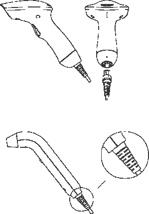
Connecting the scanner
-
Keyboard wedge/RS-232C/USB:
Connect the 10-pins RS-45 male connector into
the bottom of the scanner and you will hear a
“
click”
when the connection is made.
5
Power supply for
RS-232C
scanner -
There are 3 ways to supplying the power, use ex-
ternal +5V power supply, use optional power cable
(KBDC) which taking the power from KB wedge or if
the host supports +5V power from pin 9.
Installing the scanner to the Host System -
1. Turn off the host system.
2. Connect the power if needed.
3. Connect to the proper port on the host system.
4. Turn on the host system.
Switching cable -
Before removing the cable from the scanner, it is
recommended that the power on the host system is
off and the power supply has been disconnected
from unit.
1. Find the small "Pin-hole" on the bottom of the
unit.
2. Use a bended regular paperclip and insert the
tip into the hole.
3. You will head a
"
click
"
, then gentle on the strain-
relief of the cable and it will slide out of the
scanner.
SG/LG Series
SD Series

6
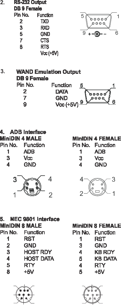
1.5 Pin Assig
nment
A> Input Port for Mini Decoder
DB 9 Male
Pin No. Wand / CCD /
Slot Reader La
s
er Scanner
1 N.C. S.O.S.
2 DATA DATA
3 N.C. N.C.
4 N.C. N.C.
5 N.C. TRIGGER
6 N.C. P. E.
7
GND GND
8
SHIELD SHIELD
9
+5V +5V
1 5
6 9
B> Output Port
1. PC Keyboard Output
DIN 5 MALE DIN 5 FEMALE
Pin No. Function Pin No. Function
1 HOST CLK 1 KB CLK
2 HOST DATA 2 KB DATA
4 GND 4 GND
5 Vcc(+5V) 5 Vcc(+5V)
1 3
3 1
4 5
5
4
2
2
MiniDIN 6 MALE MiniDIN 6
)
EMALE
Pin No. Function Pin No. Function
1 HOST DATA 1 KB DATA
3 GND 3 GND
4 Vcc 4 Vcc
5 HOST CLK 5 KB CLK
3
1
5
2
4
6
2
4
6
1
3
5
7
6 7 8 8 7
6
3 5 5 3
1 2 2 1
4 4
Power Lead

8
Chapter 2 Configuration - G
eneral
2.1 Flow Chart
9
2.2 Loop of Programming
The philosophy of programming parameters
has been shown on the flow chart of 2.1.
Basically user should
1. Scan Start of Configuration.
2. Scan all necessary labels for parameters that meet
applications.
3. Scan End of Configuration to end the programming.
4. To permanently save the settings you programmed,
just scan label for Save Parameters.
5.
To go back to the Default Settings, just scan label
for Set All Defaults
.
2.3 Factory Default Settings
The factory default settings are shown with <>
and bold in the following
sections. You
can
make your own settings by following the
procedures in this manual. If you want to save the
settings permanently, you should scan the label of
“Save Parameters“ in chapter 2.4,otherwise the
settings will not be saved after the decoder
power is off, and all settings will go back to
previous settings.
By scanning “Set All Default“ label, the settings
will go back to the factory default settings.

10
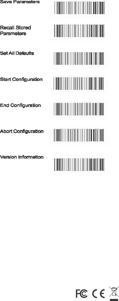
2.4 Main Page of Configuration
Save Parameters
%$
+
/0
Recall Stored
Parameters
Set AII Defaults
%$
+
/ 1
%$
+
/ 2
Start Configuration
%$
+
/ 3
End Configuration
%$
+
/ 4
Abort Configuration
%$
+
/ 6
Version Information
%$
+
/ 5
Save Parameters
-
The parameter settings will be saved permanently.
Recall Stored Parameters -
Replace the current parameters by the parameters
you saved last time.
Set AII Defaults -
Set all the parameters to the factory default settings.
Abort Configuration -
Terminate current programming status.
Version Information -
Display the decoder version information and date
code.

12
Chapter 3 Interface and
Reading Mode Selection
3.1 Interface SeIection
USB Mode
%0XO
8
RS232 Mode
%0
0U8

12
3.2 Reading Mode Selection
<Good
Read OFF>
%
0
271
Trigger ON/OFF
Continuous/Trigger OFF
%
0
2 7 0
%
0
272
Testing
%
0
275
Continuous/Auto Power On
%
0
273
Flash
%
0
274
Flash/Auto Power On
%
0
27 6
Reserved1
Auto Sense(Option)
%
0
277
%
09 F
8
Reserved3
Reserved4
%
09 F
9
%
09FA
Reserved5
%
09 F
B

13
Ch.4 Communication Parameters
4.1 RS232 Communication Parameters
A> Set
Up
BAUD Rate
1200
2400
% 0
Y71
% 0
Y7
2
4800
<9600>
% 0
Y7
3
%0
Y7
7
19200
38400
%0Y74
%0
Y7
5
57600
%0Y78
115200
%0Y79

13
B> Set U
p
Data Bits
7 Data Bits
%0
Y80
<8 Data Bits>
C> Set
Up
Stop Bits
%0
Y8
8
<1 Bit>
2 Bits
%0YO8
%0
YO0

1
4
D> Set Up Parity
<None>
%0YN7
Even
Odd
%0YN 2
%0YN3
Mark
Space
%0YN1
%0
YN0
E Handshaking
RTS/CTS Enable
%0
188
<RTS/CTS Disable>
ACK/NAK Enable
%0
1 8 0
%0
144
<ACK/NAK Disable>
XON/XOFF Enable
%0 1 4 0
%0
3
K4
<XON/XOFF Disable>
%0
3
K0

15
4.2 Keyboard Wedge Mode Parameters
A > Terminal Type
<IBM PC/AT, PS/2>
%0
ZF0
IBM PC/XT
IBM PS/2 25, 30
%0
ZF1
%0
ZF2
NEC 9800
Apple Desktop Bus(
ADB
)
%0
ZF3
%0
ZF4
IBM 5550
IBM 122 Key (1)
%0
ZF5
%0
ZF6
IBM 102 Key
IBM 122 Key (2)
%0
ZF7
%0
ZF8
Reserved 1
Reserved 2
%0
ZF9
%0
ZFA
Reserved 3
Reserved 4
%0
ZFB
%0
ZFC
Reserved 5
% 0
ZFD

1
6
B> Upper/Lower Case
<No Change>
%0
33 0
Upper Case
%0
331
Lower Case
%0
332
C>
Caps Lock
Detection
Enable
%0
X8
8
<Disable>
%0
X80
D> Send Character by ALT Method
Enable
%03O 8
E> Select Numerical
Pad
ON
<Disable>
%03O0
%0
1K
4
<OFF>
% 0
1K
0

17
4.3 Output Characters Parameters
A> Select Terminator
<CR+LF>
% 7
S2
+
None
% 7
S7
+
CR
% 7
S
0
+
LF
Space
% 7
S1
+
% 7
S4
+
HT(TAB)
% 7
S3
+
STX-ETX
% 7
S5
+

18
B> Time-out Between Characters
<0 ms>
%0070
5 ms
%0071
10 ms
%0072
25 ms
50 ms
%0073
%
0074
100 ms
200 ms
%0075
%0076
300 ms
%0077

19
4.4 Wand Emulation Mode Parameters
A> TTL Level Representation
<Bar Equals
High>
%0
2
K4
Bar Eq
uals L
ow
%0
2
K0
B> Scan Speed Selection
<Fast>
%0
28 8
Slow
%0
280
C> Output Format Selection
<Output as Code 39>
%0
2
O8
Output as Code 39
Full ASCII
%0
2
O0
Output as Original
Code Format
%0
XK4

20
Ch.5 Bar Codes & Others
5.1 SymboIogies Selection
UPC-A <ON>
%0
A4
4
OFF
UPC-E <ON>
%0
A40
%0 BO8
OFF
EAN-13/JAN-13/ISBN-13
<ON>
%0
BO0
%0
A
22
OFF
EAN-8/JAN-8 <ON>
%0
A20
%0
A1
1
OFF
CODE 39 <ON>
%0
A10
%0 EO8
OFF
CODE 128 <ON>
%0
EO0
%0
F
O8
OFF
CODABAR/NW7
<ON>
%0
F
O0
%0 J O8
OFF
%0 J O 0

Interleave 25 <ON>
%0GO8
OFF
Industrial 25 ON
%0GO0
%0HO8
<OFF>
Matrix 25 ON
%0HO0
%0
I O8
<OFF>
CODE 93 ON
%0
I
O0
% 0
KO8
<OFF>
%0
KO0
CODE 11 ON
<OFF>
% 0 LO8
%0 L O 0
China Postage ON
% C
M O8
<OFF>
MSI/PLESSEY
ON
%0
M O0
% C
NO8
<OFF>
%0
NO0
21

Code 2 of 6ON
%0
PO8
<OFF>
LCD25 ON
%0
PO
C
%0QO8
<OFF>
Telepen ON
%0 QO0
% 0
TO8
<OFF>
Reserved5 ON
% 0
TO0
<OFF>
% 0
RO8
%0
RO0
Reserved6 ON
% 0
SO8
<OFF>
%0
SO0
22

GS1 DataBar Omnidirectional ON
% 0
UO8
<OFF>
GS1 DataBar Limited ON
% 0
UO0
% 0V
O8
<OFF>
%0VO0
GS1 DataBar Expanded ON
% 0WO8
<OFF>
Select All Bar Codes
% 0WO0
% 1
A/+
23

5.2 UPC/EANI/JAN Parameters
A Reading Type
UPCA=EAN13 ON
%0
AK4
UPCA=EAN13<OFF>
ISBN-1C
Enable
%0
B8
8
%0
AK0
ISBN-13 <Enable>
ISSN Enable
%0 B 8 0
%0
B4
4
ISSN <Disable>
Decode with Supplement
%0
B40
%0
1O0
<Auto discriminate
Supplement>
Expand UPC-E
Enable
%0
1
O8
%0
BH1
Expand UPC-E
<Disable>
EAN8=EAN13
Enable
%0
BH0
%0 A O 8
EAN8=EAN13
<Disable>
GTIN Format
Enable
%0
AO0
%0 X 4 4
GTIN Format
<Disable>
%0
X4
0
24

B> Supplemental Set Up
<Not Transmit>
%0
B3
3
Transmit 5 Code
Transmit 2 Code
%0
B3
1
%0
B3
2
Transmit 2&5 Code
C> Check
Digit Transmission
UPC-A Check Digit
Transmission <ON>
%0
B3
0
%0
AI2
UPC-E Check Digit
Transmission <ON>
OFF
%0
AI 0
OFF
%0
BI2
EAN-8 Check Digit
Transmission <ON>
%0BI0
OFF
%0
A8
8
EAN-13 Check Digit
Transmission <ON>
%0
A80
OFF
%0AH1
ISSN Check Digit
Transmission <ON>
%0
AH0
OFF
%0BK4
% 0 B K 0
25

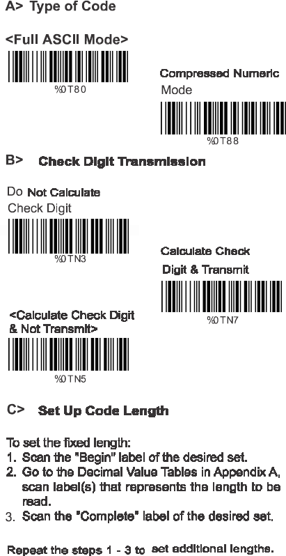
5.3 Code 39 Parameters
A> Type of Code
<Standard>
%0EH1
Full ASCII
Italian Pharmacy/Code 32
<OFF>
%0
EH0
%0
E8
0
Italian Pharmacy/
Code 32 ON
%0
E88
B> Check Digit Transmission
<Do Not Calculate
Check Digit>
%0EM 2
Calculate Check Digit
& Transmit
Calculate Check Digit
& Not Transmit
%0EM 6
%0EM 4
C> Output Start/Stop Character
Enable
%0
E4
4
<Disable>
%0 E 4 0
26

D>
Decode
Asterisk
Enable
%0
E2
2
< Disable>
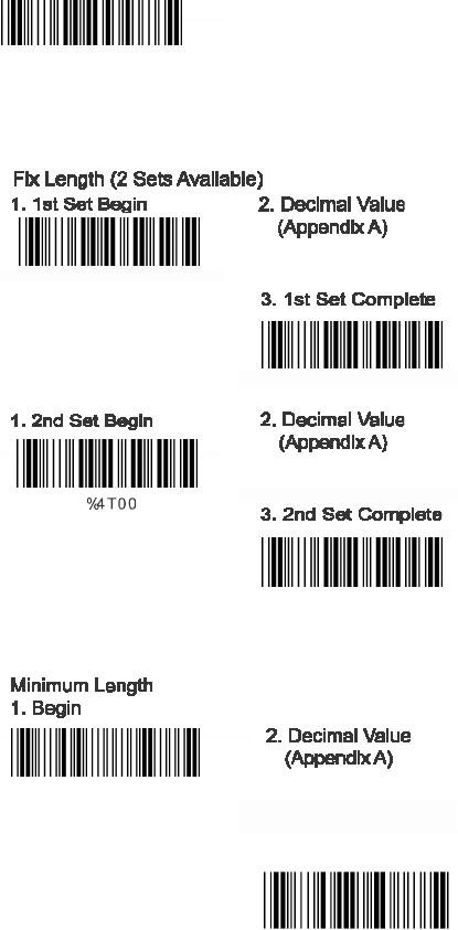
E>
Set Up Code Length
%0
E20
To set the fixed
length:
1
.
Scan the “Begin“ label of the desired set.
2. Go to the Decimal Value Tables in Appendix A,
scan label(s) that represents the length to be
read.
3. Scan the “Complete“ label of the desired set.
Repeat the steps 1
- 3 to set
additional
lengths.
<Variable>
% 4
E1
+
Fix Length (2 Sets Available)
1. 1st Set Begin 2. Decimal Value
(Appendix A)
% 4E00
3.
1st
Set Complete
% 4E01
1. 2nd Set Begin 2. Decimal Value
(Appendix A)
% 4E00
3. 2nd Set Complete
Minimum Length
% 4E0
2
1.
Begin 2. Decimal Value
(Appendix A)
3. Complete
% 2
+
- /
%2C0+
27

5.4
Code
128 Parameters
A> Reading Type
UCC/EA1-128
Enable
%0
F4
4
<Enable’]C1’Code
Format>
%0 F 2 2
<Enable Code128
Group Separators(GS)>
<UCC/EA1-128
Disable>
%0
F40
Disable‘]C1‘Code
Format
%0
F20
%0
F1
1
Disable Code128
Group Separators(GS)
B>
Check
Digit Transmission
Do Not Calculate
Check Digit
%0
F10
%0
F
N1
Calculate Check
Digit & Transmit
<Calculate Check
Digit& Not Transmit>
%0
F
N7
%0
F
N5
C> Append FNC2
ON
%0
F8
8
<OFF>
%0F80
28

D> Set
Up
Code
Length
To set the fixed l
ength
1. Scan the “Begin“ label of the desired set.
2. Go to the Decimal Value Tables in Appendix A
scan label(s) that represents the length to be
read.
3. Scan the “Complete“ label of the desired set.
Repeat the steps 1 - 3 to set additional lengths.
<Variable>
% 4
E1
+
Fix Length (2 Sets Available)
1. 1st Set Begin 2. Decimal Value
(Appendix A)
% 4F
0 0
3. 1st Set Complete
% 4F
0
1
1. 2nd Set Begin 2. Decimal Value
(Appendix A)
% 4
F00
3. 2nd Set Complete
% 4F
0
2
Minimum Length
1. Begin 2. Decimal Value
(Appendix A)
% 2
+
- /
3. Complete
% 2
C1+
29

5.5 Interleave 25 Parameters
A>
Check
Digit Transmission
<Do Not Calculate
Check Digit>
% 0G
N3
Calculate Check Digit
& Transmit
%0GN7
Calculate Check Digit
& Not Transmit
%0GN5
B Set Up Number of Character
<Even>
%0
G8
8
Odd
%0
G8
0
C Brazilian Banking Code
<Disable>
%0
G4
0
Enable
%0G44
30

D> Set
8p
Code
Length
To set the fixed
length:
1. Scan the “Begin“ label of the desired set.
2. Go to the Decimal Value Tables in Appendix A,
scan label(s) that represents the length to be
read.
3. Scan the “Complete“ label of the desired set.
Repeat the steps 1 - 3 to set additional lengths.
<Variable>
% 4G1
+
Fix Length (2 Sets Available>
1.1st Set Beg 2. Decimal Value
(Appendix A)
% 4G00
3. 1st Set Complete
% 4G01
1.2nd Set Begin 2. Decimal Value
(Appendix A)
% 4G00
3. 2nd Set Complete
% 4G0 2
Minimum Length
1. Begin 2. Decimal Value
(Appendix A)
% 2
+
- /
3. CompIete
% 2C2
+
31

5.6 IndustriaI 25 Parameters
A> Reading type
IATA25 Enable
%0H44
<Disable>
B Check Digit Transmission
<Do Not Calculate
Check Digit>
%0
H4
0
Calculate Check Digit
& Transmit
%0HN3
%0HN7
Calculate Check Digit
& Not Transmit
% 0
HN5
C> Set Up Code Length
To set the fixed length
1. Scan the “Begin“ label of the desired set.
2. Go the Decimal Value Tables in Appendix A,
scan label(s) that represents the length to be
read.
3. Scan the “Complete“ label of the desired set.
Repeat the steps 1 - 3 to set additional lengths.
32

<Variable>
% 4
H1
+
Fix Length (2 Sets Available>
1. 1st Set Begin 2. Decimal Value
(Appendix A)
% 4
H00
3. 1st Set Complete
% 4
H01
1. 2nd Set Begin 2. Decimal Value
(Appendix A)
%4H00
3. 2nd Set Complete
%4
H02
Minimum Length
1. Begin 2. Decimal Value
(Appendix A)
%2
+
- /
3. Complete
%2
C3
+
33

5.7 Matrix 25 Parameters
A>
Check
Digit Transmission
<Do Not Calculate
Check Digit>
% 0 I N 3
Calculate Check Digit
& Transmit
% 0 I N 7
Calculate Check Digit
& Not Transmit
% 0 I N 5
B> Set Up
Code
Length
To set the fixed
length:
1. Scan the “Begin“ label of the desired set.
2. Go to the Decimal Value Tables in Appendix A,
scan label(s) that represents the length to be
read.
3. Scan the “Complete“ label of the desired set.
Repeat the steps 1 - 3 to set additional lengths.
34

<Variable>
%4
I
1
+
Fix Length (2 Sets Available)
1. 1st Set Begin 2. Decimal Value
(Appendix A)
% 4
I00
3. 1st Set Complete
% 4
I01
1. 2nd Set Begin 2. Decimal Value
(Appendix A)
% 4
I00
3. 2nd Set Complete
%4
I0
2
Minimum L
ength
1. Begin 2. Decimal Value
(Appendix A)
%2
+
- /
3. Complete
%2
C4
+
35

5.8 CODABAR/NW7 Parameters
A> Set Up Start/Stop Characters Upon
Transmission
ON
%C
J H
1
<OFF>
%0
J H0
B> Transmission Type of Start/Stop
<A/B/C/D> <Start>
%0
4
V
F
<A/B/C/D> <Stop>
A Start
%0
4
F
F
%0
4
V
1
A Stop
B Start
%0
4
F
1
%0
4
V
2
B Stop
%0
4
F
2
C Start
C Stop
%0 4 V 4
D Start
%0
4
F
4
D Stop
%0
4 V 8
% 0 4 F 8
36

C> Set Up Code Length
To set the fixed length:
1. Scan the “Begin“ label of the desired set.
2. Go
to the Decimal Value Tables in Appendix A,
scan label(s) that represents the length to be
read.
3. Scan the “Complete“ label of the desired set.
Repeat the steps 1 - 3 to set additional lengths.
<Variable>
%4
J
1
+
Fix Length (2 Sets Available)
1. 1st Set Begin 2. Decimal Value
(Appendix A)
%4
J00
3. 1st Set Complete
% 4
J0
1
1. 2nd Set Begin 2. Decimal Value
(Appendix A)
%4
J00
3. 2nd Set Complete
%4
J0
2
Minimum L
ength
1. Begin 2. Decimal Value
(Appendix A)
%2
+
- /
3. Complete
% 2C5+
37

5.9 Code 93 Parameters
A>
Check
Digit Transmission
<Calculate Check 2 Digits
& Not Transmit>
%0
KN4
Do Not Calculate
Check Digit
%0
KN3
B> Set Up Code Length
To set the fixed length:
1. Scan the “Begin“ label of the desired set.
2. Go to the Decimal Value Tables in Appendix A,
scan label(s) that represents the length to be
read.
3. Scan the “Complete“ label of the desired set.
Repeat the steps 1 - 3 to set additional lengths.
38

<Variable>
% 4
K1
+
Fix Length (2 Sets Available)
1. 1st Set Begin 2. Decimal Value
(Appendix A)
% 4
K0
0
3. 1st Set Complete
% 4
K0
1
1. 2nd Set Begin 2. Decimal Value
(Appendix A)
% 4
K0
0
3. 2nd Set Complete
% 4
K0
2
Minimum L
ength
1. Begin 2. Decimal Value
(Appendix A)
% 2
+
- /
3. Complete
% 2
C6
+
39

5.10 Code 11 Parameters
A> Check Digit Transmission
<Do Not Calculate
Check Digit>
%0 L N 3
Calculate Check 1
Digit & Transmit
Calculate Check 1 Digits
& Not Transmit
%0 L N 7
%0 L N 5
Calculate Check 2
Digits & Transmit
%0 L N 6
Calculate Check 2 Digits
& Not Transmit
% 0 L N 4
B> Set Up Code Length
To set the fixed length:
1. Scan the “Begin“ label of the desired set.
2. Go to the Decimal Value Tables in Appendix A,
scan label(s) that represents the length to be
read.
3. Scan the “Complete“ label of the desired set.
Repeat the steps 1 - 3 to set additional lengths.
40

<Variable>
% 4L 1 +
Fix Length (2 Sets Av
ailable
)
1. 1st Set Begin 2. Decimal Value
(Appendix A)
%4L00
3. 1
st
Set Complete
%4L01
1. 2nd Set Begin 2. Decimal Va
l
ue
(Appendix A)
%4 L 0 0
3. 2nd Set Complete
%4 L 0 2
Minimum Length
1.
Begin 2. Decimal Value
(Appendix A)
% 2
+
- /
3. Complete
% 2C7
+
41

5.11 MSI/PLESSEY Code Parameters
A>
Check
Digit Transmission
Do Not Calculate
Check Digit
%
O
NN3
Calculate
Check Digit
& Transmit
<Calculate Check Digit
& Not Transmit>
%
O
NN7
%
O
NN5
B> Set U
p
Code
Length
To set the fixed length:
1. Scan the “Begin“ label of the desired set.
2. Go to the Decimal Value Tables in Appendix A,
scan label(s) that represents the length to be
read.
3. Scan the “Complete“ label of the desired set.
Repeat the steps 1
- 3 to set additional lengths.
42

<Variable>
% 4
N1
+
Fix Length (2 Sets Av
ailable
)
1. 1st Set Begin 2. DecimaI Va
I
ue
(Appendix A)
% 4
N0
0
3. 1
st
Set Complete
% 4
N0
1
1. 2nd Set Begin 2. DecimaI Va
I
ue
(Appendix A)
% 4
N0 0
3. 2nd Set Complete
% 4
N02
Minimum Length
1. Begin 2. Decimal Value
(Appendix A)
% 2
+
- /
3. Complete
% 2
C9
+
43

5.12
Code
2 of 6 Parameters
A>
Check
Digit Transmission
<Do Not Calculate
Check Digit>
% 0 PN3
Calculate Check
Digit & Transmit
Calculate Check Digit
& Not Transmit
% 0
P N 7
% 0
P N 5
B> Set U
p
Code
Length
To set the fixed length:
1. San the “Begin“ label of the desired set.
2. Go to the Decimal Value Tables in Appendix A,
scan label(s) that represents the length to be
read.
3. Scan the “Complete“ label of the desired set.
Repeat the steps 1
- 3 to set additional lengths.
44

<Variable>
%4
P1
+
Fix Length (2 Sets Available)
1. 1st Set Begin 2. Decimal
V
alue
(Appendix A)
%4
P0
0
3. 1st Set Complete
%4
P01
1. 2nd Set Begin 2. Decimal
V
alue
(Appendix A)
%4
P0
0
3. 2nd Set Complete
% 4
P02
Minimum L
ength
1. Begin 2. Decimal
V
alue
(Appendix A)
% 2
+
- /
3. Complete
% 2
CB+
45

5.13 LCD25 Parameters
A> Check Digit Transmission
<Do Not Calculate
Check Digit>
% 0QN3
Calculate Check Digit
& Transmit
%0 Q N 7
Calculate Check
Digit & Not Transmit
% 0 Q N 5
B> Setup Code length
To set the fixed length:
1. Scan the “Begin“ label of the desired set.
2. Go to the Decimal Value Tables in Appendix A,
scan label(s) that represents the length to be
read.
3. Scan the “Complete“ label of the desired set.
Repeat the steps 1 - 3 to set additional lengths.
46

<Variable>
% 4
Q1
+
Fix Length (2 Sets Available)
1. 1st Set Begin 2. Decimal
V
alue
(Appendix A)
% 4Q0
0
3. 1st Set Complete
% 4Q01
1. 2st Set Begin 2. Decimal
V
alue
(Appendix A)
% 4Q0
0
2. 2nt Set Complete
% 4Q02
Minimum L
ength
1. Begin 2. Decimal
V
alue
(Appendix A)
%2
+
- /
3. Complete
% 2CC+
47
5.14 Telepen Parameters
48
<Variable>
%4T1+
%4T00
%4T01
%4T02
%2%+-/
%2CF+
49
3. Complete

5.15 GS1 Databar
A> GS1 DataBar Omnidirectionl
<Transmit Check Digit>
%0UN7
Don’t Transmit
Check Digit
%0UN5
%0U88
Don’t Transmit
Application ID
Transmit Symbology ID
%0U80
%0U44
<
Don’t Transmit
Symbology ID>
%0U40
B>
GS1 DataBar Limited Parameters
<Transmit Check Digit>
%0VN7
Don’t Transmit
Check Digit
%0VN5
50
<Transmit
Application ID>

<Transmit Application ID>
%0
V88
Don‘t Transmit
Application ID
Transmit Symbology ID
%0
V80
%0
V4 4
<Don‘t Transmit
Symbology ID>
%0
V4 0
C> GS1 DataBar Expanded Parameters
Transmit Symbology ID
%0 W
44
<Don‘t Transmit
Symbology ID>
%0 W
40
51

Ch.6 Miscellaneous Parameters
6.1 Language Selection
<US English>
%0
Z
V0
UK English
Italian
%0
Z
V1
%0
Z
V2
Spanish
French
%0
Z
V3
%0
Z
V4
German
Swedish
%0
Z
V5
%0
Z
V6
Switzerland
Hungarian
%0
Z
V7
%0
Z
V8
Japanese
%0
Z
V9
52

Belgium
%0
Z V
A
Portuguese
Denmark
%0 Z V
B
%0
Z V
C
Netherlands
Turkey
%0 Z V
D
% 0 Z
V
E
Reserved2
%0 Z V
F
53

6.2 Bar Code ID
ON
%0 0 H1
<OFF>
%0 0
H0
Default
%9
13+
With
this function ON, a leading character will
be added to the output string while scanning code,
user may refer to the following table to know what
kind of bar code is being scanned.
Please refer to the table below for matching code
ID of codes read in.
Code Type ID Code Type ID
UPC-A A
EAN-8 C
CODE 39 E
Interleave 25 G
Matrix 25 I
CODE 93 K
China Postage M
Code 2 of 6 P
Telepen T
GS1 DataBar V
UPC-E B
EAN-13 D
CODE 128
F
Industrial 25 H
Codabar/NW7
J
CODE 11
L
MSI/PLESSEY N
LCD25 Q
GS1 DataBar U
Omnidirectional
GS1 DataBar W
User Define Code ID
To set the code ID:
1. Scan the symbologies label.
2. Go to the ASCII Tables in Appendix B, scan label
that represents the desired code ID.
Note:
User define code ID will override default value.
Program will not check the conflict. It is possible to
have more than two symbologies which have same
code ID.
54

UPC-A
%9
1
A+
UPC-E
EAN-13/JAN-13
%9
1
B+
%9 1Y+
EAN-8/JAN-8
CODE 39
%9
1
Z
+
%9
1
E+
CODE 128
CODABAR/NW7
%9
1
F
+
%9
1
J +
Interleave 25
Industrial 25
%91G+
% 9
1
H
+
Matrix 25
CODE 93
% 9
1
I +
% 9
1
K+
CODE 11
ChinaPostage
% 9
1L+
% 9
1
M+
MSI/PLESSEY
% 9
1
N+
55

Code 2 of 6
% 9
1
P+
Telepen
LCD25
% 91T
+
% 91
Q
+
GS1 DataBar
Omnidirectional ON
GS1 DataBar
Limited ON
% 91
U+
%
91V
+
GS1 DataBar
Expanded ON
Reserved5
% 91
W+
% 9
1
R+
Reserved6
% 9
1
S+
56

6.3 Reading Level
Bar
Equals H
igh
%0
3
I 2
<Bar Equals Low>
6.4 Accuracy
<1 Time>
%0
3
I 0
%0
13 0
2 Times
3 Times
%0
131
%0
13 2
4 Times
6.5 Buzzer Beep Tone
<High>
%0
133
%0
1
J 3
Medium
Low
%0
1
J 2
%0
1
J 1
Off
%0
1
J
0
57
(
V
-
1040/LG700
)

6.6 Sensitivity of Continuous Read
ing Mode
A> Quick Setting:
<Fast>
%0
388
Slow
%0
3
8
0
B> Same Code Delay Reading Interval
Following code sequences represent the
length of time before a barcode can be
rescanned at continuous and flash reading
mode. The value can be defined from 1-50
and they represent 100ms to 5 seconds in
100ms interval. Default value is 3 (0.3 seconds).
To setup same code delay reading interval:
1.Scan the "Begin" label
2.Go the Decimal Value Tables in Appendix A,
Scan label(s),that represents the same code
delay reading interval. They are ranged form
1-50.One step is represented 0.1second.So
the interval is from 0.1 to 5 seconds.
3.Scan the "Complete" label
Repeat the steps 1-3 to set time out of same
symbol
1.Begin 2.Decimal Value
(1-50) (Appendix A)
3.Complete
58
6.7 Reverse Output Characters
<Disable>
Enable
%03H0
Enable
%03H1
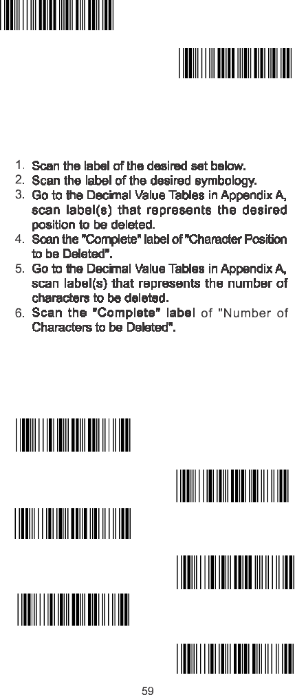
6.8 Setup Deletion
To setup the deletion of output characters:
Repeat the steps 1 – 6 to set additional deletion.
A> Select Deletion Set Number
1. 1st Set
%800+
2. 2nd Set
3rd Set
%801+
%802+
4. 4th Set
5th Set
%803+
%804+
6. 6th Set
%805+
3.
5
.

B>
SymboIogies Selection
UPC-A
% 8
1
A+
UPC-E
EAN-13/JAN-13/ISBN-13
% 8
1
B+
% 8
1
Y
+
EAN-8/JAN-8
CODE 39
% 8
1
Z
+
% 8
1
E+
CODE 128
CODABAR/N97
% 8
1
F
+
% 8
1
J +
Interleave 25
Industrial 25
% 8
1 G+
% 8
1
H
+
Matrix 25
CODE 93
% 8
1
I +
% 8
1
K+
CODE 11
China Postage
% 8
1L+
% 8
1
M+
MSI/PLESSEY
% 8
1
N+
60

Code 2 of 6
% 81P+
Telepen
%81T+
LCD25
GS1 DataBar
Omnidirectional
%81 Q+
%81U+
GS1 DataBar
Limited
GS1 DataBar
Expanded
%
81V
+
% 81W+
All Codes
None
% 8
1
S+
% 814+
C>
Character Position to be Deleted
1. Decimal
V
alue
(Appendix A) 2. Complete
%8 20+
D>
Number of Characters to be Deleted
1. Decimal
V
alue
(Appendix A) 2. Complete
%8 30+
61

6.9 Setup Insertion
To setup the insertion of output characters
1. Scan the label of the desired set.
2. Scan the label of the desired symbology.
3. Go to the Decimal Value Tables in Appendix A, scan
label(s) that represents the desired position to be
inserted.
4. Scan the “Complete“ label of “Character Position
to be Inserted“.
5. Go to the ASCII Tables in Appendix B or Function
Key Tables in Appendix C, scan label(s) that
represents the desired characters to be inserted.
6. Scan the “Complete“ label of “Characters to be
Inserted“.
Repeat the steps 1 - 6 to set additional insertion.
A> Select Insertion Set Number
1. 1st Set
% 5
00+
2. 2nd Set
3. 3rd Set
% 5
01+
% 5
02+
4. 4th Set
5. 5th Set
% 5
03+
% 5
04+
6. 6th Set
% 5
05+
62

B>
SymboIogies Selection
UPC-A
% 51
A+
UPC-E
EAN-13/JAN-13/ISBN-13
% 51
B+
% 51Y+
EAN-8/JAN-8
CODE 39
% 51
Z
+
% 51
E+
CODE 128
CODABAR/NW7
% 51F
+
% 51
J+
Interleave 25
Industrial 25
% 5 1 G +
% 5 1 H +
Matrix 25
CODE 93
% 5 1 I +
% 5 1 K +
CODE 11
China Postage
% 5 1 L +
% 5 1 M +
MSI/PLESSEY
% 5 1 N +
63

Code 2 of 6
Telepen
%51P+
% 51T
+
LCD255
GS1 DataBar
Omnidirectional
% 5 1 Q +
% 51
U+
GS1 DataBar
Limited
GS1 DataBar
Expanded
%
51V
+
%
51W+
All Codes
None
% 5
1
S+
% 5
14+
C>
Character Position to be Inserted
1. Decimal
V
alue
(Appendix A) 2. Complete
% 5
2 0 +
D>
Characters to be Inserted
1. ASCII Table
(Appendix B) 2. Complete
% 5
3 0 +
64

6.10 Scanning Line Selection for Multi
Parallel lines modes
**Only for V-1040(BT)/LG700(BT)**
<Double Click to Interchange
Multi Parallel / Single line>
Multiple Parallel Lines Only
Single Line Only
65

Ch7. Bluetooth Configuration
BT Parameter Set Default
7.1 Scanner Mode
A>Setup SPP Master Mode
<SPP Master Mode>
Please follow the steps to setup the communication
between the scanner and dongle.
1) The scanner must scan “SPP Master Mode”
barcode to set the scanner in master mode.
2) Scan the Bluetooth MAC address code located
on the bottom of the dongle.
3) When the Bluetooth MAC address code was
successfully scanned, scanner will sound 3 short
beeps with green LED flash once.
4) Wait approximately five seconds for completing
the connection process with up-tone.
5) If successful, blue LED of scanner will slow flash
and the dongle will be continued on.
B>Setup SPP Slave Mode
SPP Slave Mode
Please follow the below steps to setup the
communication between the scanner and Bluetooth
application device.
1) The scanner must scan “SPP Slave Mode”
barcode, to set the scanner in slave mode.
2) When control the Bluetooth device to search the
scanner, enter pin code (default 00:00:00) to
setup comport.
3) When scanner is successful connected, the
scanner blue LED will also blink with up-tone.
Blue LED will slowly flash to finish the setup.
66

C>Setup HID Slave Mode
HID Slave Mode
To setup the communication between the scanner and
Bluetooth HID profile application device, follow the
steps.
1) The scanner must scan “HID Slave Mode”
barcode to set the scanner in HID slave mode.
2) When control the Bluetooth device to search the
scanner, enter pin code to setup pairing. You can
scan number barcode on Appendix D, “Decimal
Value Table II” number 0~9, to setup.
3) When scanner is successful connected, scanner
blue LED will also blink with up-tone. Blue LED
will slowly flash to finish the setup.
7.2 Out of Range
When “Out of Range” function is enabled, and the
scanner is working at out of transmission range, the
scanned data will be stored to out-of-range memory.
Memory size is approximately 25,000 sets of EAN13
barcode type. The all stored data will be transmitted to
device when the link is reconnected, and the all data
stored in out-of-range memory will be cleared.
<Out of Range Enable>
Out of Range Disable
67

7.3 Sleep Mode
The scanner is equipped with sleep mode function
to save battery energy when the scanner is not used
for 1 minute or 10 minutes. During sleep mode, all
the functions and connection will be halted until
pressing the trigger button. The communication with
dongle or Bluetooth device will be reconnected.
Sleep Mode 1 min. ON
Sleep Mode10 min. ON
<Sleep Mode OFF>
7.4 Batch Mode
“***” means “Quick Setting Label”. The function can be
executed directly by scanning barcode instead of doing the
general programming process.
Batch Mode On
< Batch Mode Off>
*** Batch Data Read
*** Batch Data Clear
***Delete Last Data
68

7.5 Firmware Version
Display the firmware version of the scanner, please
scan below barcode.
Scanner Firmware Version
Dongle Firmware Version
Scanner MAC Address
Dongle MAC Address
69

Appendix
A Decimal Value Table
0
1
2
3
4
5
6
7
8
9
70

Appendix B ASCII Table
NULL
SOH
00
ETX
03
ACK
C6
HT
C9
FF
0C
SI
0 F
DC2
12
NAK
15
CAN
18
ESC
1B
RS
STX
0 2
ENQ
0 5
BS
0 8
VT
0B
SO
0E
DC1
11
DC4
14
ETB
17
SUB
1A
GS
1D
0 1
EOT
0 4
BEL
0 7
LF
0A
CR
0D
DLE
1 0
DC3
13
SYN
16
EM
19
FS
1C
US
1E 1F
71

SPACE !
2 0
“
21
#
22
$
23
%
24
&
25
‘
26
(
27
)
28
*
29
+
2A
,
2B
-
2C
.
2D
/
2E
0
2F
1
30
2
31
3
32
4
33
5
34
6
35
7
36
8
37
9
38
:
39
;
3A
<
3B
=
3C
>
3D
?
3E 3F
72

@ A
40
B
41
C
42
D
43
E
44
F
45
G
46
H
47
I
48
J
49
K
4A
L
4B
M
4C
N
4D
O
4E
P
4F
Q
5 0
R
51
S
52
T
5 3
U
54
V
55
W
56
X
57
Y
58
Z
59
[
5A
\
5B
]
5C
^
5D
_
5E 5F
73

a
`
60
b
c
62
63
e
f
65
66
h
i
68
69
k
l
6B
6C
n
o
6E
6F
q
r
71
72
t
u
74
75
w
x
77
78
z
﹛
7A
7B
}
~
7D
61
d
64
g
67
j
6A
m
6D
p
7C
s
73
v
76
y
79
|
7C
DEL
7E 7F
74

Appendix C Function Key Table
F1 F2
C0 C1
F3
C2
F4 F5
C3 C4
F6
C5
F7 F8
C6 C7
F9
C8
F10 F11
C9 CA
F12
CB
Insert Delete
CC CD
Home
CE
Page Up Page Down
CF D0
End
D1
Left Right
D2 D3
Up
D4
Down
D5
75
Appendix D
Decimal Value Table II
0
1
2
3
4
5
6
7
8
9
Enter
76
All above programming are subject to change without
notice.
Ver3.9
0145-85E00I1
%$+/0
%$+/1
%$+/2
%$+/3
%$+/4
%$+/6
%$+/5